EP1566664B1 - Capteur de lumiere, mecanisme de detection et mecanisme de mesure de la lumiere utilises dans un dispositif d'analyse - Google Patents
Capteur de lumiere, mecanisme de detection et mecanisme de mesure de la lumiere utilises dans un dispositif d'analyse Download PDFInfo
- Publication number
- EP1566664B1 EP1566664B1 EP03774116.2A EP03774116A EP1566664B1 EP 1566664 B1 EP1566664 B1 EP 1566664B1 EP 03774116 A EP03774116 A EP 03774116A EP 1566664 B1 EP1566664 B1 EP 1566664B1
- Authority
- EP
- European Patent Office
- Prior art keywords
- light
- sensor
- emitting
- units
- areas
- Prior art date
- Legal status (The legal status is an assumption and is not a legal conclusion. Google has not performed a legal analysis and makes no representation as to the accuracy of the status listed.)
- Expired - Lifetime
Links
- 230000007246 mechanism Effects 0.000 title claims description 62
- 239000013307 optical fiber Substances 0.000 claims description 10
- 230000001105 regulatory effect Effects 0.000 claims description 3
- 239000003153 chemical reaction reagent Substances 0.000 description 20
- 238000005259 measurement Methods 0.000 description 8
- 238000000034 method Methods 0.000 description 4
- 230000009467 reduction Effects 0.000 description 4
- 238000005253 cladding Methods 0.000 description 3
- 238000001514 detection method Methods 0.000 description 3
- 239000000428 dust Substances 0.000 description 3
- 230000001788 irregular Effects 0.000 description 2
- 239000000463 material Substances 0.000 description 2
- 230000003287 optical effect Effects 0.000 description 2
- 230000009471 action Effects 0.000 description 1
- 230000012447 hatching Effects 0.000 description 1
- 230000002452 interceptive effect Effects 0.000 description 1
- 230000001678 irradiating effect Effects 0.000 description 1
- 239000011347 resin Substances 0.000 description 1
- 229920005989 resin Polymers 0.000 description 1
- 230000004044 response Effects 0.000 description 1
- 238000007740 vapor deposition Methods 0.000 description 1
- 230000003245 working effect Effects 0.000 description 1
Images






Classifications
-
- G—PHYSICS
- G01—MEASURING; TESTING
- G01N—INVESTIGATING OR ANALYSING MATERIALS BY DETERMINING THEIR CHEMICAL OR PHYSICAL PROPERTIES
- G01N21/00—Investigating or analysing materials by the use of optical means, i.e. using sub-millimetre waves, infrared, visible or ultraviolet light
- G01N21/17—Systems in which incident light is modified in accordance with the properties of the material investigated
- G01N21/55—Specular reflectivity
-
- G—PHYSICS
- G01—MEASURING; TESTING
- G01N—INVESTIGATING OR ANALYSING MATERIALS BY DETERMINING THEIR CHEMICAL OR PHYSICAL PROPERTIES
- G01N21/00—Investigating or analysing materials by the use of optical means, i.e. using sub-millimetre waves, infrared, visible or ultraviolet light
- G01N21/17—Systems in which incident light is modified in accordance with the properties of the material investigated
- G01N21/47—Scattering, i.e. diffuse reflection
- G01N21/4738—Diffuse reflection, e.g. also for testing fluids, fibrous materials
-
- G—PHYSICS
- G01—MEASURING; TESTING
- G01N—INVESTIGATING OR ANALYSING MATERIALS BY DETERMINING THEIR CHEMICAL OR PHYSICAL PROPERTIES
- G01N21/00—Investigating or analysing materials by the use of optical means, i.e. using sub-millimetre waves, infrared, visible or ultraviolet light
- G01N21/84—Systems specially adapted for particular applications
- G01N21/8483—Investigating reagent band
-
- G—PHYSICS
- G01—MEASURING; TESTING
- G01N—INVESTIGATING OR ANALYSING MATERIALS BY DETERMINING THEIR CHEMICAL OR PHYSICAL PROPERTIES
- G01N2201/00—Features of devices classified in G01N21/00
- G01N2201/08—Optical fibres; light guides
Definitions
- the present invention relates to a technique for analyzing a specific component of a sample with use of a test tool.
- an optical method For analyzing a specific component contained in a sample, use may be made of an optical method.
- An example of such is one that utilizes a color reaction occurring in a test tool.
- the degree of coloration occurring on the test tool may be checked with eyes.
- an appropriate analyzing device is used.
- Some analyzing devices are designed to begin automatic measurement for the amount of specific component after a test tool has been set in the device.
- Such an analyzing device includes a light source 992 for irradiating a reagent pad 991 of the test tool 990, and a light-receiving unit 993 for receiving the scattered light from the reagent pad 991, whereby analysis of the sample is performed on the basis of the quantity of light received by the light-receiving unit 993 (see JP-A-H09-145613 , for example).
- the test tool 990 is irradiated directly with the light from the light source 992, and the scattered light from the test tool 990 is received directly in the light-receiving unit 993.
- the light source 992 and the light-receiving unit 993 need be disposed such that the light reception axis S2 of the light-receiving unit 993 is inclined relative to the light emission axis S1 of the light source 992.
- the distance between the light source 992 and the light-receiving unit 993 tends to be large, thereby making it difficult to reduce the size of a light-measuring mechanism employing the above method, and hence the size of the analyzing device incorporating the light-measuring mechanism.
- the quantity of light received in the light-receiving unit 993 is small. Unfavorably, this increases the likelihood of measurement errors.
- the analyzing device needs to recognize that a test tool has been supplied.
- recognition of a test tool is automatically performed in the analyzing device, though it is also possible to arrange that the recognition is initiated by the user operating an operation switch on the device.
- the automatic recognition (detection) of the test tool in the analyzing device is attained through a light sensor.
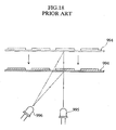
- a light sensor An example of such a light sensor, shown, in Fig. 18 , uses scattered light from a test tool 994.
- the light source 995 emits light toward a target site in which the test tool 994 is to be placed.
- the light-receiving unit 996 it is determined that the test tool 994 is placed in the target site.
- reflection light is received in the light-receiving unit 996 not only when the test tool 994 is placed in the target site, but also when the user's hand passes over the target site or the test tool 994 is brought above the target site.
- the analyzing device may erroneously recognize that the test tool 994 has been properly set in the target site, and begin an analysis operation.
- JP-2000-089394-A discloses a detecting sensor which includes a prism arranged between a light projecting section and a light receiving section.
- the prism has a first boundary surface on which projected light is made incident, a second boundary surface which emits the incident light from the first boundary surface towards a tray, a third boundary surface on which light reflected from the tray is made incident and a fourth boundary surface which emits the incident light from the third boundary surface to the light receiving device side.
- the respective boundary surfaces are so constituted that light which is not emitted towards the tray and is reflected at the second boundary surface is totally reflected at the fourth boundary surface.
- An object of the present invention is to reduce the size of a light sensor that may be used as a light-measuring mechanism of an analyzing device, and thereby reducing the overall size of the analyzing device incorporating such a light-measuring mechanism.
- Another object of the present invention is to prevent erroneous detection in detecting a test tool in an analyzing device employing an optical method.
- the present invention is a light sensor as defined in claim 1 of the appended claims. Also provided is an analyzing device as defined in claim 17.
- a first embodiment of the present invention provides a light sensor comprising: one or more light-emitting units for emitting light onto a target object; and one or more light-receiving units for receiving reflection light from the target object.
- the one or more light-emitting units and the one or more light-receiving units are disposed such that a light emission axis of the one or more light-emitting units and a light reception axis of the one or more light-receiving units are parallel or substantially parallel to each other.
- a second embodiment of the present invention provides a light-measuring mechanism for a test tool, comprising: one or more light-emitting units for emitting light onto a test tool used for analyzing a sample; and one or more light-receiving units for receiving reflection light from the test tool.
- the one or more light-emitting units and the one or more light-receiving units are disposed such that a light emission axis of the one or more light-emitting units and a light reception axis of the one or more light-receiving units are parallel or substantially parallel to each other.
- the light sensor or light-measuring mechanism further comprises a light guide for regulating a path of at least one of light traveling toward the target object (test tool) from the one or more light-emitting units and light traveling toward the one or more light-receiving units from the target object (test tool).
- the light guide comprises: one or more first entrance areas for introducing light emitted from the one or more light-emitting units into the light guide; one or more first output areas for outputting the light introduced into the light guide toward the target object (test tool); one or more second entrance areas for introducing reflection light from the target object (test tool) into the light guide; and one or more second output areas for outputting the light reflected by the target object (test tool) and then introduced into the light guide toward the one or more light-receiving units.
- At least one area of the one or more first entrance areas, the one or more first output areas, the one or more second entrance areas, and the one or more second output areas may be arranged to refract light passing through the above-mentioned at least one area.
- the light guide is formed with a slit disposed between the one or more first entrance areas and the one or more second output areas, the slit being configured to extend in parallel to the light emission axis or the light reception axis.
- the light guide may comprise a lens or a prism, for example.
- the one or more first output areas and the one or more second entrance areas may be formed as planar surfaces that are orthogonal or substantially orthogonal to the light emission axis of the one or more light-emitting units.
- the light guide may comprise a core portion extending along the light emission axis, and an outer shell portion having a lower refractive index than the core portion and surrounding the core portion.
- the outer shell portion may function as a cladding layer, and thus the entire light guide may be constituted as an optical fiber.
- the light guide may also be arranged such that it comprises an optical fiber portion extending along the light emission axis, and an outer shell portion surrounding the optical fiber portion.
- the light sensor and the light-measuring mechanism of the present invention may further comprise a light shield for causing light that is reflected by the target object (test tool) at a target angle, among the light reflected by the target object (test tool), to enter the one or more light-receiving units selectively.
- the target angle may be set to 45 degrees or substantially 45 degrees, for example.
- the light shield may be formed with an opening for selectively exposing the one or more first output areas and the one or more second entrance areas.
- the light shield may comprise an annular part surrounding the periphery of at least one of the one or more first output areas and the one or more second entrance areas, for example.
- the light shield may be formed with an opening for exposing the plurality of first output areas or the plurality of second entrance areas successively.
- the plurality of light-receiving units may be disposed so as to surround the single light-emitting unit.
- the plurality of light-emitting units may be disposed so as to surround the single light-receiving unit.
- the plurality of light-emitting units may preferably comprise two or more light-emitting units which emit light having different peak wavelengths.
- the one or more light-receiving units may be arranged to receive scattered light reflected by the object (test tool) among the light emitted from the one or more light-emitting units.
- the light sensor and the light-measuring mechanism may comprise a wavelength selection portion for selecting the wavelength of the light to be introduced into the one or more light-receiving units, or may comprise a wavelength selection portion for selecting the wavelength of light emitted from the one or more light-emitting units.
- the wavelength selection portion may comprise an interference filter or a color filter, for example.
- an analyzing device comprising: a light-measuring mechanism that includes one or more light-emitting units for emitting light onto a test tool used for analyzing a sample, and one or more light-receiving units for receiving reflection light from the test tool; and a detecting mechanism for detecting whether or not a test tool exists in a target area, including a light-emitting unit for emitting light onto the test tool, and a light-receiving unit for receiving reflection light from the test tool.
- the one or more light-emitting units and one or more light-receiving units of the light-measuring mechanism are disposed such that a light emission axis of the light-emitting units and a light reception axis of the light-receiving units are parallel or substantially parallel to each other.
- the light-receiving unit of the detecting mechanism is constituted to receive light that is reflected regularly by the test tool selectively, among the light emitted by the light-emitting unit of the detecting mechanism.
- the light-measuring mechanism further comprises a light guide for regulating a path of at least one of light traveling toward the test tool from the one or more light-emitting units and light traveling toward the one or more light-receiving units from the test tool.
- the light guide comprises: one or more first entrance areas for introducing light emitted from the one or more light-emitting units into the light guide; one or more first output areas for outputting the light introduced into the light guide toward the test tool; one or more second entrance areas for introducing reflection light from the target object into the light guide; and one or more second output areas for outputting the light reflected by the target object and then introduced into the light guide toward the one or more light-receiving units.
- At least one area of the one or more first entrance areas, the one or more first output areas, the one or more second entrance areas, and the one or more second output areas may be arranged to refract light passing through the above-mentioned at least one area.
- the light guide is formed with a slit disposed between the one or more first entrance areas and the one or more second output areas, the slit being configured to extend in parallel to the light emission axis or the light reception axis.
- the term "light emission axis” denotes an axis extending in the direction of the largest quantity of emitted light over the distribution of the light quantity emitted from the light-emitting unit.
- the term “light reception axis” denotes an axis extending along the normal at a point where the quantity of received light is the largest over the the distribution of the light quantity received in the light-receiving unit.
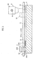
- an analyzing device 1 includes a housing 2, in which a stage 3, a detecting mechanism 4, a conveying mechanism 5, and a light-measuring mechanism 6 are provided.
- a plurality of operating buttons 20 and a display 21 are provided on the housing 2 together with an introduction portion 22 for placing a test tool 7 on the stage 3.
- the introduction portion 22 is formed as a cutout that communicates with the interior of the housing 2 and exposes a part of the stage 3.
- a strip-like base 70 upon which a plurality of reagent pads 71 are arranged at intervals in the longitudinal direction of the base 70.
- Each reagent pad 71 contains a reagent which develops color in response to a specific component of a sample.
- the stage 3 comprises a guide portion 30 for guiding the movement of a sliding block 50 of the conveying mechanism 5 to be described below, and also comprises a recess 31 for exposing the lower surface of the test tool 7 placed on the stage 3.
- the stage 3 is provided with a placement area 32 and a light-measuring area 33.
- the placement area 32 is an area in which the test tool 7, introduced into the interior of the housing 2 through the introduction portion 22 (see Fig. 1 ), is placed.
- the light-measuring area 33 is an area in which a specific component of a sample supplied onto the reagent pad 71 is subjected to light-measurement by the light-measuring mechanism 6.
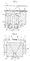
- the detecting mechanism 4 determines whether or not the test tool 7 is placed in the placement area 32, and comprises a light-emitting unit 40, a light-receiving unit 41, and the prism 42 serving as a light guide, as shown in Fig. 3 .
- the light-emitting unit 40 emits light toward the upper side of the stage 3 such that when the test tool 7 is placed in the placement area 32, the rear surface of the test tool 7 is irradiated with the light.
- the light-emitting unit 40 is fixed to the prism 42 so that a light emission axis L1 faces the thickness direction (the vertical direction in Fig. 3 ) of the stage 3.
- the light-receiving unit 41 receives light traveling from the upper side of the stage 3, and is fixed to the prism 42 so that a light reception axis L2 is parallel or substantially parallel to the light emission axis L1 of the light-emitting unit 40.
- the light-emitting unit 40 comprises a light-emitting diode, for example, while the light-receiving unit 41 comprises a photodiode, for example.
- the light-emitting unit 40 and the light-receiving unit 41 need not necessarily be fixed to the prism 42, and the detecting mechanism 4 may be constituted separately from the prism 42.
- the prism 42 comprises light-guiding portions 43, 44, and is entirely transparent.
- the light-guiding portions 43, 44 are separated by a slit 45.
- the slit 45 is provided to prevent light from the light-emitting unit 40 from being received directly in the light-receiving unit 41.
- the light-guiding portion 43 comprises a recess 46 into which the light-emitting unit 40 is fitted and fixed.
- the bottom surface of the recess 46 constitutes an entrance surface 46A for introducing light from the light-emitting unit 40 into the interior of the light-guiding portion 43.
- the entrance surface 46A is orthogonal to the light emission axis L1.
- the light-guiding portion 43 also comprises an output surface 43A for outputting light from the interior of the light-guiding portion 43 toward the upper side of the stage 3.
- the output surface 43A is formed as an inclined plane in relation to the light emission axis L1 (light reception axis L2), and serves to refract light passing through the output surface 43A.
- the light-guiding portion 44 comprises an entrance surface 44A for introducing reflection light from the test tool 7 into the interior of the light-guiding portion 44.
- the entrance surface 44A is formed as a plane having an opposite incline to the output surface 43A in relation to the light reception axis L2 (light emission axis L1), and serves to refract light passing through the entrance surface 44A. More specifically, of the light emitted toward the upper side of the stage 3 from the output surface 43A, the entrance surface 44A conducts regular reflection light from the test tool 7, placed in the placement area 32 of the stage 3, through the interior of the light-guiding portion 44 along the light reception axis L2.
- the light-guiding portion 44 also comprises a recess 47 into which the light-receiving unit 41 is fitted and fixed. The bottom surface of the recess 47 constitutes an output surface 47A for outputting light from the interior of the light-guiding portion 44 toward the light-receiving unit 41.
- the output surface 47A is orthogonal to the light reception axis L
- the detecting mechanism 4 light emitted from the light-emitting unit 40 is introduced into the light-guiding portion 43 through the entrance surface 46A, travels along the light emission axis L1, and is then outputted from the light-guiding portion 43 toward the upper side of the stage 3 through the output surface 43A.
- the test tool 7 is not present in the placement area 32 of the stage 3, the light outputted from the light-guiding portion 43 is not received in the light-receiving unit 41.
- the rear surface of the test tool 7 is irradiated with the light output from the light-guiding portion 43, and the resulting reflection light enters the entrance surface 44A of the light-guiding portion 44.
- light that is reflected regularly on the rear surface of the test tool 7 is selectively introduced into the light-guiding portion 44.
- the light introduced into the light-guiding portion 44 travels along the light reception axis L2, and is then outputted from the output surface 47A and received in the light-receiving unit 41.
- the detecting mechanism 4 regular reflection light produced when the test tool 7 is placed in the placement area 32 is actively introduced into the light-guiding portion 44 of the prism 42 and received in the light-receiving unit 41. Accordingly, when the test tool 7 is not placed in the placement area 32, for example when the test tool 7 is positioned above the placement area 32 as shown by the virtual lines in Fig. 3 , the resulting regular reflection light is not introduced into the prism 42. As a result, the situations, in which the detecting mechanism 4 mistakenly detects the presence of the test tool 7 even though the test tool 7 is not placed in the placement area 32, can be suppressed.
- a light-emitting diode has lower directivity than a laser diode. Therefore, by employing a light-emitting diode as the light-emitting unit 40 of the detecting mechanism 4, light from the light-emitting unit 40 widens when outputted from the light-guiding portion 43, as shown in Fig. 4 . Hence, by employing a light-emitting diode as the light-emitting unit 40, light can be emitted in a comparatively wide range, enabling an increase in the range in which the presence of the test tool 7 can be detected. As a result, the test tool 7 can be detected even when a user places the test tool 7 manually such that the test tool 7 is not positioned with exactitude, thereby lessening the burden on the user when placing the test tool 7.
- the light-emitting unit 40 and light-receiving unit 41 are disposed such that the light emission axis L1 and light reception axis L2 are parallel to each other. In so doing, the distance between the light-emitting unit 40 and light-receiving unit 41 can be reduced in comparison with a constitution inwhich the light-emitting unit and light-receiving unit are disposed such that the light emission axis and light reception axis are not parallel to each other. As a result, a reduction in the size of the detecting mechanism 4, and a corresponding reduction in the size of the analyzing device 1, can be achieved.
- the conveying mechanism 5 serves to move the test tool 7 from the placement area 32 to the light-measuring area 33 of the stage 3.
- the conveying mechanism 5 comprises the sliding block 50, which is capable of a reciprocating motion over the upper surface of the stage 3 in a direction indicated by arrows D1, D2 in the drawings, and a guiding rod 51 for causing the sliding block 50 to perform this reciprocating motion.
- the sliding block 50 comprises an interfering portion 50A which slides over the upper surface of the stage 3, and a connecting portion 50B connected to the guiding rod 51 so as to be capable of moving relative thereto.
- a through hole 50b formed with a thread groove (not shown) on its inner surface is provided in the connecting portion 50B.
- a thread ridge (not shown) is formed on the surface of the guiding rod 51, and hence the guiding rod 51 is screwed to the sliding block 50 via the through hole 50b.
- the guiding rod 51 is rotated, for example, by linking the guiding rod 51 to a power source such as a motor, not shown in the drawing, and using the output of the power source.
- the light-measuring mechanism 6 optically measures the degree of coloration of the reagent pads 71 on the test tool 7.
- the light-measuringmechanism 6 comprises a slider 60 capable of a reciprocating motion along the surface of the stage 3 in a direction indicated by arrows D3, D4 in the drawings, a guiding rod 61 for causing the slider 60 to perform this reciprocating motion, and the light sensor 8 carried on the slider 60.
- the slider 60 comprises a through hole 60b formed with a thread groove (not shown) on its inner surface.
- a thread ridge (not shown) is formed on the surface of the guiding rod 61, and hence the guiding rod 61 is screwed to the slider 60 via the through hole 60b.
- the guiding rod 61 is rotated, for example, by linking the guiding rod 61 to a power source such as a motor, not shown in the drawing, and using the output of the power source.
- the light sensor 8 comprises a light-emitting unit 80, a light-receiving unit 81, and a prism 82.
- the light-emitting unit 80 emits light toward the stage 3, and is fixed to the prism 82 such that a light emission axis L3 extends in the thickness direction (the vertical direction in Fig. 7 ) of the stage 3.
- the light-receiving unit 81 receives light traveling from the stage 3, and is fixed to the prism 82 such that a light reception axis L4 is parallel or substantially parallel to the light emission axis L3 of the light-emitting unit 80.
- the light-emitting unit 80 comprises a light-emitting diode, for example, while the light-receiving unit 81 comprises a photodiode, for example.
- the prism 82 comprises a light-guiding portion 83 and a light-guiding portion 84, and is entirely transparent. These areas 83, 84 are separated by a slit 85.
- the slit 85 is provided to prevent light from the light-emitting unit 80 from being received directly in the light-receiving unit 81.
- the light-guiding portion 83 comprises a recess 86 into which the light-emitting unit 80 is fitted and fixed.
- the bottom surface of the recess 86 constitutes an entrance surface 86A for introducing light from the light-emitting unit 80 into the interior of the light-guiding portion 83.
- the entrance surface 86A is orthogonal to the light emission axis L3.
- the light-guiding portion 83 also comprises an output surface 83A for outputting light from the interior of the light-guiding portion 83 toward the test tool 7.
- the output surface 83A is formed as an inclined plane in relation to the light emission axis L3 (light reception axis L4), and serves to refract light passing through the output surface 83A.
- the light-guiding portion 84 comprises an entrance surface 84A for introducing light from the test tool 7 into the interior of the light-guiding portion 84.
- the entrance surface 84A is orthogonal to the light reception axis L4 (light emission axis L3). More specifically, of the light emitted toward the test tool 7 from the output surface 83A, the entrance surface 84A conducts scattered light from the test tool 7, traveling along the light reception axis L4, through the interior of the light-guiding portion 84 along the light reception axis L4 without refracting the light.
- the light-guiding portion 84 also comprises a recess 87 into which the light-receiving unit 81 is fitted and fixed.
- the bottom surface of the recess 87 constitutes an output surface 87A for outputting light from the interior of the light-guiding portion 84 toward the light-receiving unit 81.
- the output surface 87A is orthogonal to the light reception axis L4.
- the light sensor 8 is moved in the direction of the arrows D3, D4 in the drawing (the length direction of the test tool 7) together with the slider 60 by rotating the guiding rod 61.
- the light-measuring mechanism 6 by emitting light from the light-emitting unit 80 while moving the light sensor 8 in the length direction of the test tool 7, all of the plurality of reagent pads 71 can be irradiated with light.
- the scattered light from each reagent pad 71 can be received in the light-receiving unit 81.
- the light-emitting unit 80 and light-receiving unit 81 are disposed such that the light emission axis L3 and light reception axis L4 are parallel to each other.
- the distance between the light-emitting unit 80 and light-receiving unit 81 in the light sensor 8 can be reduced in comparison with a constitution in which a light-emitting unit 80' and the light-receiving unit 81 are disposed such that a light emission axis L3' and the light reception axis L4 are not parallel to each other, as shown by the virtual lines in Fig. 9 .
- a reduction in the size of the light sensor 8, and a corresponding reduction in the size of the light-measuring mechanism 6 and the analyzing device 1 can be achieved.
- the output surface 83A is inclined in relation to the light emission axis L3 (light reception axis L4), while the entrance surface 84A is orthogonal to the light reception axis L4 (light emission axis L3).
- the output surface may be orthogonal to the light emission axis L3 (light reception axis L4) and the entrance surface 84A inclined in relation to the light reception axis L4 (light emission axis L3), or both the output surface and entrance surface may be inclined in relation to the light emission axis L3 and light reception axis L4.
- the present invention is not limited to the embodiment described above.
- constitutions such as those shown in Figs. 10A to 10E may be employed as a detecting mechanism
- constitutions such as those shown in Figs. 11 to 16 may be employed as a light sensor.
- the light guide is constituted as a prism 42A, where the prism 42A corresponds in arrangement to the prism 42 of the detecting mechanism 4 (see Fig. 3 , for example) turned upside down.
- the light guide is constituted as a cylindrical lens 42B.
- the light guide is constituted as a Fresnel lens 42C.
- the Fresnel lens 42C comprises a plurality of protruding portions 42Ca such that its upper surface is irregular.
- the detecting mechanism 4C also comprises a cover 42Cb covering the protruding portions 42Ca.
- the upper surface of the detecting mechanism 4C is made planar.
- a cover 42Db is formed integrally with the upper surface (irregular surface) of a Fresnel lens 42D.
- the upper surface of this detecting mechanism 4D is also planar.
- the upper surface of the light guide is planar, and therefore the height dimension of a central portion can be reduced in comparison with a case in which the upper surface is pointed or curved (see Figs. 3 , 10A, and 10B ).
- the dimensions of the detecting mechanisms 4C, 4D can be reduced.
- dust or dirt can be prevented from adhering to the upper surface of the Fresnel lenses 42C, 42D.
- the dust or dirt adheres to the covers 42Cb, 42Db, which have fewer irregularities than the Fresnel lenses 42C, 42D, the dust and dirt can be removed easily.
- the light guide is constituted as a lens 42E combining a cylindrical lens and a Fresnel lens.
- the upper surface of the lens 42E may be covered with a cover.
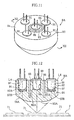
- a light sensor 8A shown in Figs. 11 and 12 comprises a single light-emitting unit 90, four light-receiving units 91, and a light guide 92 formed in a transparent columnar form.
- the light guide 92 is formed with an annular recess 95. This recess 95 divides the light guide 92 into a light-guiding portion 93 and a light-guiding portion 94.
- the light-guiding portion 93 takes a columnar form, and comprises a recess 96 to which the light-emitting unit 90 is fixed.
- the light-emitting unit 90 comprises a white LED, for example.
- a bottom surface 96A of the recess 96 constitutes an entrance surface for introducing light emitted from the light-emitting unit 90 into the light-guiding portion 93.
- the entrance surface 96A is orthogonal to the light emission axis L3 of the light-emitting unit 90.
- the light-guiding portion 93 also comprises an output surface 93A for outputting light from the interior of the light-guiding portion 93 to the outside.
- the output surface 93A is constitutedas a plane that is orthogonal to the light emission axis L3 (parallel to the entrance surface 96A).
- the light-guiding portion 94 takes an annular form, and comprises an entrance surface 94A which is inclined in relation to the light reception axes L4 of the light-receiving units 91.
- the entrance surface 94A is constituted as a curved surface.
- the light-guiding portion 94 comprises four recesses 97 to which the light-receiving units 91 are fixed.
- the recesses 97 are provided concentrically so as to surround the recess 96 of the light-guiding portion 93.
- the four light-receiving units 91 are disposed so as to surround the light-emitting unit 90, and such that the light reception axes L4 thereof are parallel to the light emission axis L3 of the light-emitting unit 90.
- a bottom surface 97A of each recess 97 constitutes an output surface for introducing light into the light-receiving units 91.
- a wavelength selection portion 97B is provided on the bottom portion of each recess 97.
- the four wavelength selection portions 97B each transmit light of different wavelengths. Accordingly, light of different wavelengths is selected in each light-receiving unit 91.
- the wavelength selection portions 97B are constituted by interference filters or color filters, for example.
- the light sensor 8A of the light that is emitted from the light-emitting unit 90 and reflected on the reagent pads 71, light of different wavelengths is received in each light-receiving unit 91. Hence, even when the test tool 7 is constituted to measure a plurality of analysis items corresponding to different measurement wavelengths, appropriate measurement can be performed by setting the wavelength to be selected by the wavelength selection portions 97B.
- the light emission axis L3 of the light-emitting unit 90 and the light reception axis L4 of each light-receiving unit 91 are disposed parallel to each other. In so doing, in the light sensor 8A, the size of the light sensor 8A, and accordingly the size of the light-measuring mechanism, can be reduced in a similar manner to the light sensor 8 (see Figs. 7 through 9 ) described above.
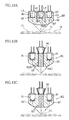
- a light sensor 8B shown in Fig. 13A comprises four light-emitting units 90' and a single light-receiving unit 91' such that the arrangement of the light-emitting unit and light-receiving units in the light sensor 8A (see Figs. 11 and 12 ) is switched. More specifically, the light-receiving unit 91' is disposed in the central portion of the light guide 92, and the four light-emitting units 90' are disposed so as to surround the light-receiving unit 91'.
- the light-emitting units 90' and light-receiving unit 91' are disposed so that the light emission axis L3 of each light-emitting unit 90' is parallel to the light reception axis L4 of the light-receiving unit 91'.
- a wavelength selection portion 96B' is provided on the bottom portion of a recess 96' to which the light-receiving unit 91' is fixed. Accordingly, only light of a specific wavelength enters the light-receiving unit 91'. It should be noted that the wavelength selection portion 96B' may be omitted.
- the reagent pads 71 are irradiated with light from the four light-emitting units 90', and reflection light from the reagent pads 71 is received in the single light-receiving unit 91'. Therefore, in the light sensor 8B, the quantity of light emitted onto the reagent pads 71 can be increased, thus securing a larger quantity of reception light in the light-receiving unit 91'. As a result, even when light measurement is performed on the basis of scattered light, which tends to produce a small quantity of reception light, for example, the light can be measured appropriately.
- wavelength selection portions may be provided on recesses 97' to which the light-emitting units 90' are fixed such that the wavelength of light entering the light guide 92 from each recess 97' is selected.
- each wavelength selection portion may be constituted to transmit light of the same wavelength or light of a different wavelength, depending on the constitution of the test tool 7.
- the output light-guiding portion of the light sensor 8A (see Figs. 11 and 12 ) is constituted by an optical fiber 93'.
- the optical fiber 93' comprises a core portion 93B' formed transparently, and a cladding portion 93C' surrounding the core portion 93B' and having a smaller refractive index than the core portion 93B'.
- the optical fiber 93' is surrounded by an outer shell portion 94'.
- the reagent pads 71 can be irradiated efficiently with light from the light-emitting unit 90 due to the action of the optical fiber 93'. As a result, the quantity of light received in the light-receiving unit 91 can be increased.
- a light guide 92" is constituted by a core portion 93" and an outer shell portion 94" surrounding the core portion 93".
- the core portion 93" has a higher refractive index than the outer shell portion 94”
- the outer shell portion 94" functions as a cladding layer
- the entire light guide 92" constitute an optical fiber.
- the reagent pads 71 can be irradiated efficiently with light from the light-emitting unit 90, and therefore the quantity of light received in the light-receiving unit 91 can be increased.
- a light-shielding mask 88 is deposited so as to cover the output surface 93A and entrance surface 94A of the light guide 92 in the light sensor 8A shown in Figs. 11 and 12 .
- the light-shielding mask 88 causes light reflected on the reagent pads 71 at an angle of 45 degrees or substantially 45 degrees to enter the light guide 92, and accordingly the light-receiving units 91.
- the entire light-shielding mask 88 is formed from a material which absorbs light easily, and as shown in Fig. 14B , is formed with five through holes 88a, 88b corresponding to the sum total of the light-emitting unit 90 and light-receiving units 91.
- the part shaded in cross hatching denotes the light-shielding mask 88.
- the through hole 88a transmits light emitted from the light-emitting unit 90 and output from the light guide 92, whereas the through holes 88b transmit light reflected by the reagent pads 71 toward the light guide 92.
- This type of light-shielding mask 88 may be formed by vapor deposition or printing using a black resin material, for example.
- the light sensor 8E of the light that is reflected on the reagent pads 71, only light reflected at an angle of 45 degrees or substantially 45 degrees is received in the light-receiving unit 91, and the remaining light is absorbed by the light-shielding mask 88. Hence, target reflection light required for light measurement can be caused to enter the light-receiving units 91 selectively, and therefore, if the light sensor 8E is used, the analysis precision is improved.
- the light-shielding means may take the forms shown in Figs. 15A and 15B .
- a light-shielding mask 88' shown in Fig. 15A a through hole 88b' is formed in annular form for transmitting light that is reflected by the reagent pads 71 (see Fig. 14A ) toward the light guide 92.
- the light entering all of the light-receiving units 91 is restricted by the single through hole 88b'.
- the light-shielding means shown in Fig. 15B comprise four annular light-shielding masks 88" provided individually for each light-receiving unit 91.
- a light shield 89 is provided separately from the light guide 92 and disposed at a remove from the light guide 92.
- the light shield 89 is formed with through holes 89a, 89b in a similar arrangement to the light-shielding masks 88, 88' shown in Figs. 14B and 15A .
- the light shield 89 is fixed to the slider 60 (see Fig. 7 ), for example, so as to move together with the light guide 92.
- the light-shielding masks 88, 88' , 88" and the light shield 89, described with reference to Figs. 14 through 16 are examples, and the form thereof may be modified in various ways as long as the target reflection light can be received selectively in the light-receiving unit.
- the light shield may be employed not only in the light sensors shown in Figs. 11 and 12 , but also in the other light sensors.
Landscapes
- Health & Medical Sciences (AREA)
- Life Sciences & Earth Sciences (AREA)
- Physics & Mathematics (AREA)
- Chemical & Material Sciences (AREA)
- Analytical Chemistry (AREA)
- Biochemistry (AREA)
- General Health & Medical Sciences (AREA)
- General Physics & Mathematics (AREA)
- Immunology (AREA)
- Pathology (AREA)
- Molecular Biology (AREA)
- Investigating Or Analysing Materials By Optical Means (AREA)
Claims (17)
- Capteur de lumière (8) comprenant : une ou plusieurs unités émettrices de lumière (40, 80, 90) pour émettre de la lumière sur un objet cible (71) ; et une ou plusieurs unités réceptrices de lumière (41, 81, 91) pour recevoir la lumière de réflexion en provenance de l'objet cible (71) ;
cas dans lequel lesdites une ou plusieurs unités émettrices de lumière (40, 80, 90) et lesdites une ou plusieurs unités réceptrices de lumière (41, 81, 91) sont disposées de sorte qu'un axe d'émission de lumière (L1, L3) desdites une ou plusieurs unités émettrices de lumière (40, 80, 90) et qu'un axe de réception de lumière (L2, L4) desdites une ou plusieurs unités réceptrices de lumière (41, 81, 91) soient parallèles ou sensiblement parallèles l'un à l'autre ;
le capteur de lumière (8) comprenant en outre un guide de lumière (30, 42, 92) pour réguler un trajet de l'un au moins des éléments suivants, à savoir la lumière se déplaçant vers l'objet cible (71) à partir desdites une ou plusieurs unités émettrices de lumière (40, 80, 90) et la lumière se déplaçant vers lesdites une ou plusieurs unités réceptrices de lumière (41, 81, 91) en provenance de l'objet cible (71) ;
cas dans lequel le guide de lumière (30, 42, 92) comprend : une ou plusieurs premières zones d'entrée (46A, 86A, 96A) afin d'introduire la lumière émise à partir desdites une ou plusieurs unités émettrices de lumière (40, 80, 90) dans le guide de lumière (30, 42, 92) ; une ou plusieurs premières zones de sortie (43A, 83A, 93A) afin de délivrer la lumière introduite dans le guide de lumière (30, 42, 92) vers l'objet cible (71) ; une ou plusieurs deuxièmes zones d'entrée (44A, 84A, 94A) afin d'introduire la lumière de réflexion en provenance de l'objet cible (71) dans le guide de lumière (30, 42, 92) ; et une ou plusieurs deuxièmes zones de sortie (47A, 87A, 97A) afin de délivrer la lumière réfléchie par l'objet cible (71) et ensuite introduite dans le guide de lumière (30, 42, 92) vers lesdites une ou plusieurs unités réceptrices de lumière (41, 81, 91) ;
cas dans lequel au moins une zone parmi les suivantes, à savoir lesdites une ou plusieurs premières zones d'entrée (46A, 86A, 96A), lesdites une ou plusieurs zones de sortie (43A, 83A, 93A), lesdites une ou plusieurs deuxièmes zones d'entrée (44A, 84A, 94A), et lesdites une ou plusieurs deuxièmes zones de sortie (47A, 87A, 97A), assure la réfraction de la lumière passant à travers ladite au moins une zone ; et
caractérisé en ce que le guide de lumière (30, 42, 92) est formé avec une fente (45, 85, 95) laquelle est disposée entre lesdites une ou plusieurs premières zones d'entrée (46A, 86A, 96A) et lesdites une ou plusieurs deuxièmes zones de sortie (47A, 87A, 97A), la fente (45, 85, 95) étant configurée de façon à se prolonger en parallèle à l'axe d'émission de lumière (L1, L3) ou à l'axe de réception de lumière (L2, L4). - Capteur de lumière (8) selon la revendication 1, le guide de lumière (30, 42, 92) comprenant une portion coeur (93B', 93") laquelle s'étend le long de l'axe d'émission de lumière (L1, L3), et une portion enveloppe externe (94', 94") possédant un indice de réfraction lequel est inférieur à la portion coeur (93B', 93") et entourant la portion coeur (93B', 93").
- Capteur de lumière (8) selon la revendication 1, le guide de lumière (30, 42, 92) comprenant une portion fibre optique (93') laquelle s'étend le long de l'axe d'émission de lumière (L1, L3), et une portion enveloppe externe (94', 94") laquelle entoure la portion fibre optique (93').
- Capteur de lumière (8) selon la revendication 1, comprenant en outre un pare-lumière (88, 89) qui oblige la lumière réfléchie au niveau d'un angle cible par un objet cible (71), parmi la lumière réfléchie par un outil d'essai (7), à pénétrer dans lesdites une ou plusieurs unités réceptrices de lumière (41, 81, 91) de façon sélective.
- Capteur de lumière (8) selon la revendication 1, lesdites une ou plusieurs unités émettrices de lumière (40, 80, 90) comprenant une unité individuelle émettrice de lumière (40, 80, 90), lesdites une ou plusieurs unités réceptrices de lumière (41, 81, 91) comprenant une pluralité d'unités réceptrices de lumière (41, 81, 91),
cas dans lequel la pluralité d'unités réceptrices de lumière (41, 81, 91) est agencée de façon à entourer l'unité individuelle émettrice de lumière (40, 80, 90). - Capteur de lumière (8) selon la revendication 1, lesdites une ou plusieurs unités émettrices de lumière (40, 80, 90) comprenant une pluralité d'unités émettrices de lumière (40, 80, 90), lesdites une ou plusieurs unités réceptrices de lumière (41, 81, 91) comprenant une unité individuelle réceptrice de lumière (41, 81, 91),
cas dans lequel la pluralité d'unités émettrices de lumière (40, 80, 90) est agencée de façon à entourer l'unité individuelle réceptrice de lumière (41, 81, 91). - Capteur de lumière (8) selon la revendication 1, le guide de lumière (30, 42, 92) comprenant une lentille (42B-E) ou un prisme (42A).
- Capteur de lumière (8) selon la revendication 1, lesdites une ou plusieurs premières zones de sortie (43A, 83A, 93A) et lesdites une ou plusieurs deuxièmes zones d'entrée (44A, 84A, 94A) étant constituées en tant que surfaces planes qui sont orthogonales ou sensiblement orthogonales à l'axe d'émission de lumière (L1, L3) desdites une ou plusieurs unités émettrices de lumière (40, 80, 90).
- Capteur de lumière (8) selon la revendication 4, l'angle cible étant de 45 degrés ou sensiblement 45 degrés.
- Capteur de lumière (8) selon la revendication 4, le pare-lumière étant formé avec une ouverture afin d'exposer de façon sélective lesdites une ou plusieurs premières zones de sortie (43A, 83A, 93A) et lesdites une ou plusieurs deuxièmes zones d'entrée (44A, 84A, 94A).
- Capteur de lumière (8) selon la revendication 4, le pare-lumière comprenant une partie annulaire laquelle entoure une périphérie de l'un au moins des postes suivants, à savoir lesdites une ou plusieurs premières zones de sortie (43A, 83A, 93A) et lesdites une ou plusieurs deuxièmes zones d'entrée (44A, 84A, 94A).
- Capteur de lumière (8) selon la revendication 4, lesdites une ou plusieurs premières zones de sortie (43A, 83A, 93A) ou lesdites une ou plusieurs deuxièmes zones d'entrée (44A, 84A, 94A) du guide de lumière (30, 42, 92) comprenant une pluralité de premières zones de sortie (43A, 83A, 93A) ou une pluralité de deuxièmes zones d'entrée (44A, 84A, 94A), et
cas dans lequel le pare-lumière est formé avec une ouverture afin d'exposer la pluralité de premières zones de sortie (43A, 83A, 93A) et la pluralité de deuxièmes zones d'entrée (44A, 84A, 94A) en succession. - Capteur de lumière (8) selon la revendication 6, la pluralité d'unités émettrices de lumière (40, 80, 90) comprenant deux ou plusieurs unités émettrices de lumière (40, 80, 90) qui émettent de la lumière ayant différentes longueurs d'ondes de crête.
- Capteur de lumière (8) selon la revendication 1, l'unité réceptrice de lumière (41, 81, 91) étant constituée de façon à recevoir de la lumière dispersée laquelle est réfléchie par l'objet cible (71) parmi la lumière émise par l'unité émettrice de lumière (40, 80, 90).
- Capteur de lumière (8) selon la revendication 1, comprenant en outre une ou plusieurs portions de sélection de longueurs d'ondes pour obliger la lumière réfléchie par l'objet cible (71) à pénétrer dans lesdites une ou plusieurs unités réceptrices de lumière (41, 81, 91) après la sélection d'une longueur d'onde.
- Capteur de lumière (8) selon la revendication 1, comprenant en outre une ou plusieurs portions de sélection de longueurs d'ondes pour délivrer la lumière, émise à partir desdites une ou plusieurs unités émettrices de lumière (40, 80, 90), vers l'objet cible (71) après la sélection d'une longueur d'onde.
- Dispositif d'analyse selon la revendication 1, comprenant :un mécanisme de détection (4) incluant une unité émettrice de lumière (40, 80, 90) pour émettre de la lumière sur l'objet cible (71) afin de détecter si l'outil d'essai (7) existe ou non dans une zone cible, et une unité réceptrice de lumière (41, 81, 91) pour recevoir la lumière de réflexion en provenance de l'objet cible (71) ; etcas dans lequel l'unité réceptrice de lumière (41, 81, 91) du mécanisme de détection (4) est agencée de façon à recevoir la lumière qui est régulièrement réfléchie par l'objet cible (71) de façon sélective, parmi la lumière émise par l'unité émettrice de lumière (40, 80, 90) du mécanisme de détection (4).
Applications Claiming Priority (5)
| Application Number | Priority Date | Filing Date | Title |
|---|---|---|---|
| JP2002342104 | 2002-11-26 | ||
| JP2002342103 | 2002-11-26 | ||
| JP2002342103A JP4148761B2 (ja) | 2002-11-26 | 2002-11-26 | 試験用具の検知機構、およびこの検知機構を備えた分析装置 |
| JP2002342104A JP4088142B2 (ja) | 2002-11-26 | 2002-11-26 | 光センサ、試験用具の測光機構、およびこの測光機構を備えた分析装置 |
| PCT/JP2003/014863 WO2004051317A1 (fr) | 2002-11-26 | 2003-11-20 | Capteur de lumiere, mecanisme de detection et mecanisme de mesure de la lumiere utilises dans un dispositif d'analyse |
Publications (3)
| Publication Number | Publication Date |
|---|---|
| EP1566664A1 EP1566664A1 (fr) | 2005-08-24 |
| EP1566664A4 EP1566664A4 (fr) | 2012-01-18 |
| EP1566664B1 true EP1566664B1 (fr) | 2014-03-12 |
Family
ID=32473644
Family Applications (1)
| Application Number | Title | Priority Date | Filing Date |
|---|---|---|---|
| EP03774116.2A Expired - Lifetime EP1566664B1 (fr) | 2002-11-26 | 2003-11-20 | Capteur de lumiere, mecanisme de detection et mecanisme de mesure de la lumiere utilises dans un dispositif d'analyse |
Country Status (4)
| Country | Link |
|---|---|
| US (1) | US7382460B2 (fr) |
| EP (1) | EP1566664B1 (fr) |
| AU (1) | AU2003284613A1 (fr) |
| WO (1) | WO2004051317A1 (fr) |
Families Citing this family (15)
| Publication number | Priority date | Publication date | Assignee | Title |
|---|---|---|---|---|
| TW568772B (en) * | 2002-12-31 | 2004-01-01 | Veutron Corp | Apparatus with a combination of a point light source and a single lens |
| DE102005021383A1 (de) * | 2005-05-04 | 2006-11-09 | Robert Bosch Gmbh | Handwerkzeugmaschine mit Arbeitsfeldbeleuchtung |
| US9002438B2 (en) | 2012-05-30 | 2015-04-07 | Lucerno Dynamics | System for the detection of gamma radiation from a radioactive analyte |
| US9939533B2 (en) | 2012-05-30 | 2018-04-10 | Lucerno Dynamics, Llc | System and method for the detection of gamma radiation from a radioactive analyte |
| CN104111229A (zh) * | 2013-04-16 | 2014-10-22 | 深圳中科卉而立生物科技有限公司 | 一种光路探测装置 |
| TWI485370B (zh) * | 2013-06-04 | 2015-05-21 | Chroma Ate Inc | 發光元件點測機台 |
| WO2015189170A1 (fr) * | 2014-06-10 | 2015-12-17 | Sanofi-Aventis Deutschland Gmbh | Appareil pour déterminer des informations associées à des caractéristiques de réflexion d'une surface |
| USD739952S1 (en) * | 2014-11-18 | 2015-09-29 | Ellen Meng | Adhesive film mounted adulteration test panel |
| JP6767072B2 (ja) * | 2015-10-06 | 2020-10-14 | アズビル株式会社 | 距離設定型光電センサ |
| US10508935B2 (en) * | 2015-10-15 | 2019-12-17 | Advanced Semiconductor Engineering, Inc. | Optical module and manufacturing process thereof |
| US12357250B2 (en) | 2019-04-02 | 2025-07-15 | Lucerno Dynamics, Llc | System and method of using temporal measurements of localized radiation to estimate the magnitude, location, and volume of radioactive material in the body |
| US11802830B2 (en) * | 2019-08-30 | 2023-10-31 | Toto Ltd. | Toilet seat apparatus and excrement detection apparatus |
| US12270811B2 (en) | 2021-02-01 | 2025-04-08 | Wallac Oy | Microwell assay plate and related methods |
| AU2022213504A1 (en) | 2021-02-01 | 2023-08-10 | Wallac Oy | Lateral flow test strip readers, cartridges and related methods |
| WO2023147843A1 (fr) * | 2022-02-01 | 2023-08-10 | Wallac Oy | Bandelette de test immunochromatographique et procédés associés |
Citations (1)
| Publication number | Priority date | Publication date | Assignee | Title |
|---|---|---|---|---|
| WO2002066893A1 (fr) * | 2001-02-23 | 2002-08-29 | Wytec Holding B.V. | Dispositif d"affichage de donnees |
Family Cites Families (26)
| Publication number | Priority date | Publication date | Assignee | Title |
|---|---|---|---|---|
| US3016464A (en) * | 1959-06-10 | 1962-01-09 | Daystrom Inc | Apparatus for determining the location and thickness of a reflecting object |
| US4283146A (en) * | 1978-11-30 | 1981-08-11 | Lasag S.A. | Optical detector |
| DE3106835A1 (de) | 1981-02-17 | 1982-09-02 | Siemens AG, 1000 Berlin und 8000 München | Differenzdruck-messeinrichtung |
| JPS6110283Y2 (fr) * | 1981-03-18 | 1986-04-02 | ||
| DE8303856U1 (de) * | 1983-02-11 | 1985-11-14 | Optische Werke G. Rodenstock, 8000 Muenchen | Vorrichtung zur Ermittlung einer Oberflächenstruktur, insbesondere der Rauheit |
| JPS6035244A (ja) * | 1983-08-05 | 1985-02-23 | Victor Co Of Japan Ltd | 反射光検出器の製造方法 |
| DE3503858A1 (de) * | 1985-02-05 | 1986-08-21 | Daimler-Benz Ag, 7000 Stuttgart | Vorrichtung zur ermittlung von gestaltsfehlern niedriger ordnung |
| JPH0381582A (ja) | 1989-08-24 | 1991-04-05 | Mitsubishi Electric Corp | 圧縮機の防振装置 |
| US5160981A (en) * | 1989-09-07 | 1992-11-03 | Fuji Photo Film Co., Ltd. | Method of measuring the reflection density of an image |
| JPH0381582U (fr) * | 1989-12-12 | 1991-08-20 | ||
| JPH0543091A (ja) | 1991-08-06 | 1993-02-23 | Fuji Xerox Co Ltd | 画像読取り装置の原稿重送検知装置 |
| JPH0543091U (ja) * | 1991-11-13 | 1993-06-11 | 株式会社コパル | 多点スポツト式エリア監視装置 |
| FR2687798A1 (fr) * | 1992-02-25 | 1993-08-27 | Vens | Procede de detection de la presence d'un objet sur une surface de reception d'un convoyeur, moyens en vue de la mise en óoeuvre du procede et convoyeurs pourvus des dits moyens. |
| JP3227849B2 (ja) * | 1992-12-28 | 2001-11-12 | ソニー株式会社 | 位置検出装置 |
| US5625459A (en) * | 1995-03-03 | 1997-04-29 | Galileo Electro-Optics Corporation | Diffuse reflectance probe |
| AU676270B1 (en) | 1995-09-05 | 1997-03-06 | Bayer Corporation | Diffused light reflectance readhead |
| JP3423638B2 (ja) | 1998-07-13 | 2003-07-07 | キヤノン株式会社 | 原稿検知装置及び検知装置 |
| JP2000131405A (ja) * | 1998-10-27 | 2000-05-12 | Hitachi Ltd | リチウム電池の残存容量測定方法とその測定装置 |
| US6184991B1 (en) * | 1999-04-19 | 2001-02-06 | Hewlett-Packard | Apparatus and method of measuring dry time of printing composition |
| JP2001133395A (ja) | 1999-11-08 | 2001-05-18 | Shimadzu Corp | 光生体測定装置 |
| JP3650558B2 (ja) | 1999-11-09 | 2005-05-18 | 株式会社日立製作所 | 反射率測定装置 |
| JP3477429B2 (ja) | 2000-05-29 | 2003-12-10 | サンクス株式会社 | 漏液センサ |
| JP3617951B2 (ja) * | 2000-08-09 | 2005-02-09 | シャープ株式会社 | 光反射型センサ |
| US6509919B1 (en) | 2000-09-01 | 2003-01-21 | Eastman Kodak Company | Apparatus adapted to sense a colorant and method for sensing color and detecting a donor mispick condition |
| JP2002257837A (ja) | 2000-12-28 | 2002-09-11 | Eiken Chem Co Ltd | 試薬パッドの位置及び厚みを検出することによる尿試料供試用ノズル位置の制御方法 |
| JP4058246B2 (ja) * | 2001-04-03 | 2008-03-05 | グローリー株式会社 | 紙葉類に貼着されたテープ体の検出方法及び装置 |
-
2003
- 2003-11-20 EP EP03774116.2A patent/EP1566664B1/fr not_active Expired - Lifetime
- 2003-11-20 US US10/537,003 patent/US7382460B2/en not_active Expired - Lifetime
- 2003-11-20 WO PCT/JP2003/014863 patent/WO2004051317A1/fr not_active Ceased
- 2003-11-20 AU AU2003284613A patent/AU2003284613A1/en not_active Abandoned
Patent Citations (1)
| Publication number | Priority date | Publication date | Assignee | Title |
|---|---|---|---|---|
| WO2002066893A1 (fr) * | 2001-02-23 | 2002-08-29 | Wytec Holding B.V. | Dispositif d"affichage de donnees |
Also Published As
| Publication number | Publication date |
|---|---|
| AU2003284613A1 (en) | 2004-06-23 |
| WO2004051317A1 (fr) | 2004-06-17 |
| US7382460B2 (en) | 2008-06-03 |
| EP1566664A4 (fr) | 2012-01-18 |
| EP1566664A1 (fr) | 2005-08-24 |
| US20060076523A1 (en) | 2006-04-13 |
Similar Documents
| Publication | Publication Date | Title |
|---|---|---|
| EP1566664B1 (fr) | Capteur de lumiere, mecanisme de detection et mecanisme de mesure de la lumiere utilises dans un dispositif d'analyse | |
| EP0866329B1 (fr) | Tête de mesure pour un instrument de diagnostic photométrique | |
| DK1447658T3 (en) | Multi-wavelength reading head for use in the determination of analytes in body fluids | |
| EP0359554B1 (fr) | Système d'objets biologiques et système de comparaison d'empreintes digitales utilisant ce système | |
| EP0348182B1 (fr) | Appareil de détection de données de surfaces inégales | |
| CA2173014C (fr) | Capteur de reflectance diffuse de fibre optique | |
| EP0102189B1 (fr) | Réflectomètre | |
| CN103119422B (zh) | 成分测定装置 | |
| EP1883008A2 (fr) | Capteur tactile utilisant une fibre optique | |
| US6721471B2 (en) | Apparatus and methods relating to fluorescent optical switches | |
| EP0367097A2 (fr) | Spectromètre optique par transmission | |
| CN1717596B (zh) | 光传感器、以及分析装置的检测机构和测光机构 | |
| EP1598658A2 (fr) | Analyseur d'echantillons | |
| CN1849499A (zh) | 用于连续测定物质的装置 | |
| JP4088142B2 (ja) | 光センサ、試験用具の測光機構、およびこの測光機構を備えた分析装置 | |
| EP0649524B1 (fr) | Appareil photometrique | |
| EP2690428B1 (fr) | Dispositif de mesure de composant | |
| CN223610789U (zh) | 钻针测试装置 | |
| WO2016199304A1 (fr) | Système optique de détection de propriété optique, sonde de mesure, et dispositif de détection de propriété optique | |
| CN121311176A (zh) | 血液成分测定仪 | |
| CA2293094A1 (fr) | Commutateur optique a base de fluorescence | |
| TW201413237A (zh) | 成分測定裝置 | |
| HK1192317A (en) | Component measurement device | |
| HK1066597A (en) | Multiwavelength readhead for use in the determination of analytes in body fluids |
Legal Events
| Date | Code | Title | Description |
|---|---|---|---|
| PUAI | Public reference made under article 153(3) epc to a published international application that has entered the european phase |
Free format text: ORIGINAL CODE: 0009012 |
|
| 17P | Request for examination filed |
Effective date: 20050531 |
|
| AK | Designated contracting states |
Kind code of ref document: A1 Designated state(s): AT BE BG CH CY CZ DE DK EE ES FI FR GB GR HU IE IT LI LU MC NL PT RO SE SI SK TR |
|
| AX | Request for extension of the european patent |
Extension state: AL LT LV MK |
|
| DAX | Request for extension of the european patent (deleted) | ||
| A4 | Supplementary search report drawn up and despatched |
Effective date: 20111220 |
|
| RIC1 | Information provided on ipc code assigned before grant |
Ipc: G01N 21/86 20060101ALI20111214BHEP Ipc: G01N 21/78 20060101ALI20111214BHEP Ipc: G01N 21/47 20060101ALI20111214BHEP Ipc: G01N 21/55 20060101ALI20111214BHEP Ipc: G01V 8/14 20060101AFI20111214BHEP |
|
| 17Q | First examination report despatched |
Effective date: 20120523 |
|
| RIC1 | Information provided on ipc code assigned before grant |
Ipc: G01N 21/78 20060101ALI20130705BHEP Ipc: G01N 21/55 20060101ALI20130705BHEP Ipc: G01N 21/84 20060101ALI20130705BHEP Ipc: G01N 21/47 20060101ALI20130705BHEP Ipc: G01N 21/86 20060101ALI20130705BHEP Ipc: G01V 8/14 20060101AFI20130705BHEP |
|
| GRAP | Despatch of communication of intention to grant a patent |
Free format text: ORIGINAL CODE: EPIDOSNIGR1 |
|
| INTG | Intention to grant announced |
Effective date: 20130927 |
|
| GRAS | Grant fee paid |
Free format text: ORIGINAL CODE: EPIDOSNIGR3 |
|
| GRAA | (expected) grant |
Free format text: ORIGINAL CODE: 0009210 |
|
| AK | Designated contracting states |
Kind code of ref document: B1 Designated state(s): AT BE BG CH CY CZ DE DK EE ES FI FR GB GR HU IE IT LI LU MC NL PT RO SE SI SK TR |
|
| REG | Reference to a national code |
Ref country code: GB Ref legal event code: FG4D |
|
| REG | Reference to a national code |
Ref country code: CH Ref legal event code: EP |
|
| REG | Reference to a national code |
Ref country code: AT Ref legal event code: REF Ref document number: 656662 Country of ref document: AT Kind code of ref document: T Effective date: 20140315 |
|
| REG | Reference to a national code |
Ref country code: IE Ref legal event code: FG4D |
|
| REG | Reference to a national code |
Ref country code: DE Ref legal event code: R096 Ref document number: 60345858 Country of ref document: DE Effective date: 20140424 |
|
| REG | Reference to a national code |
Ref country code: NL Ref legal event code: VDEP Effective date: 20140312 |
|
| REG | Reference to a national code |
Ref country code: AT Ref legal event code: MK05 Ref document number: 656662 Country of ref document: AT Kind code of ref document: T Effective date: 20140312 |
|
| PG25 | Lapsed in a contracting state [announced via postgrant information from national office to epo] |
Ref country code: FI Free format text: LAPSE BECAUSE OF FAILURE TO SUBMIT A TRANSLATION OF THE DESCRIPTION OR TO PAY THE FEE WITHIN THE PRESCRIBED TIME-LIMIT Effective date: 20140312 Ref country code: CY Free format text: LAPSE BECAUSE OF FAILURE TO SUBMIT A TRANSLATION OF THE DESCRIPTION OR TO PAY THE FEE WITHIN THE PRESCRIBED TIME-LIMIT Effective date: 20140312 Ref country code: SE Free format text: LAPSE BECAUSE OF FAILURE TO SUBMIT A TRANSLATION OF THE DESCRIPTION OR TO PAY THE FEE WITHIN THE PRESCRIBED TIME-LIMIT Effective date: 20140312 |
|
| PG25 | Lapsed in a contracting state [announced via postgrant information from national office to epo] |
Ref country code: NL Free format text: LAPSE BECAUSE OF FAILURE TO SUBMIT A TRANSLATION OF THE DESCRIPTION OR TO PAY THE FEE WITHIN THE PRESCRIBED TIME-LIMIT Effective date: 20140312 Ref country code: CZ Free format text: LAPSE BECAUSE OF FAILURE TO SUBMIT A TRANSLATION OF THE DESCRIPTION OR TO PAY THE FEE WITHIN THE PRESCRIBED TIME-LIMIT Effective date: 20140312 Ref country code: EE Free format text: LAPSE BECAUSE OF FAILURE TO SUBMIT A TRANSLATION OF THE DESCRIPTION OR TO PAY THE FEE WITHIN THE PRESCRIBED TIME-LIMIT Effective date: 20140312 Ref country code: BE Free format text: LAPSE BECAUSE OF FAILURE TO SUBMIT A TRANSLATION OF THE DESCRIPTION OR TO PAY THE FEE WITHIN THE PRESCRIBED TIME-LIMIT Effective date: 20140312 Ref country code: BG Free format text: LAPSE BECAUSE OF FAILURE TO SUBMIT A TRANSLATION OF THE DESCRIPTION OR TO PAY THE FEE WITHIN THE PRESCRIBED TIME-LIMIT Effective date: 20140612 Ref country code: RO Free format text: LAPSE BECAUSE OF FAILURE TO SUBMIT A TRANSLATION OF THE DESCRIPTION OR TO PAY THE FEE WITHIN THE PRESCRIBED TIME-LIMIT Effective date: 20140312 |
|
| PG25 | Lapsed in a contracting state [announced via postgrant information from national office to epo] |
Ref country code: AT Free format text: LAPSE BECAUSE OF FAILURE TO SUBMIT A TRANSLATION OF THE DESCRIPTION OR TO PAY THE FEE WITHIN THE PRESCRIBED TIME-LIMIT Effective date: 20140312 Ref country code: SK Free format text: LAPSE BECAUSE OF FAILURE TO SUBMIT A TRANSLATION OF THE DESCRIPTION OR TO PAY THE FEE WITHIN THE PRESCRIBED TIME-LIMIT Effective date: 20140312 Ref country code: ES Free format text: LAPSE BECAUSE OF FAILURE TO SUBMIT A TRANSLATION OF THE DESCRIPTION OR TO PAY THE FEE WITHIN THE PRESCRIBED TIME-LIMIT Effective date: 20140312 |
|
| REG | Reference to a national code |
Ref country code: DE Ref legal event code: R097 Ref document number: 60345858 Country of ref document: DE |
|
| PG25 | Lapsed in a contracting state [announced via postgrant information from national office to epo] |
Ref country code: PT Free format text: LAPSE BECAUSE OF FAILURE TO SUBMIT A TRANSLATION OF THE DESCRIPTION OR TO PAY THE FEE WITHIN THE PRESCRIBED TIME-LIMIT Effective date: 20140714 |
|
| PLBE | No opposition filed within time limit |
Free format text: ORIGINAL CODE: 0009261 |
|
| STAA | Information on the status of an ep patent application or granted ep patent |
Free format text: STATUS: NO OPPOSITION FILED WITHIN TIME LIMIT |
|
| PG25 | Lapsed in a contracting state [announced via postgrant information from national office to epo] |
Ref country code: DK Free format text: LAPSE BECAUSE OF FAILURE TO SUBMIT A TRANSLATION OF THE DESCRIPTION OR TO PAY THE FEE WITHIN THE PRESCRIBED TIME-LIMIT Effective date: 20140312 |
|
| 26N | No opposition filed |
Effective date: 20141215 |
|
| REG | Reference to a national code |
Ref country code: DE Ref legal event code: R097 Ref document number: 60345858 Country of ref document: DE Effective date: 20141215 |
|
| PG25 | Lapsed in a contracting state [announced via postgrant information from national office to epo] |
Ref country code: LU Free format text: LAPSE BECAUSE OF FAILURE TO SUBMIT A TRANSLATION OF THE DESCRIPTION OR TO PAY THE FEE WITHIN THE PRESCRIBED TIME-LIMIT Effective date: 20141120 Ref country code: MC Free format text: LAPSE BECAUSE OF FAILURE TO SUBMIT A TRANSLATION OF THE DESCRIPTION OR TO PAY THE FEE WITHIN THE PRESCRIBED TIME-LIMIT Effective date: 20140312 |
|
| REG | Reference to a national code |
Ref country code: CH Ref legal event code: PL |
|
| PG25 | Lapsed in a contracting state [announced via postgrant information from national office to epo] |
Ref country code: CH Free format text: LAPSE BECAUSE OF NON-PAYMENT OF DUE FEES Effective date: 20141130 Ref country code: SI Free format text: LAPSE BECAUSE OF FAILURE TO SUBMIT A TRANSLATION OF THE DESCRIPTION OR TO PAY THE FEE WITHIN THE PRESCRIBED TIME-LIMIT Effective date: 20140312 Ref country code: LI Free format text: LAPSE BECAUSE OF NON-PAYMENT OF DUE FEES Effective date: 20141130 |
|
| REG | Reference to a national code |
Ref country code: IE Ref legal event code: MM4A |
|
| PG25 | Lapsed in a contracting state [announced via postgrant information from national office to epo] |
Ref country code: IE Free format text: LAPSE BECAUSE OF NON-PAYMENT OF DUE FEES Effective date: 20141120 |
|
| REG | Reference to a national code |
Ref country code: FR Ref legal event code: PLFP Year of fee payment: 13 |
|
| PG25 | Lapsed in a contracting state [announced via postgrant information from national office to epo] |
Ref country code: GR Free format text: LAPSE BECAUSE OF FAILURE TO SUBMIT A TRANSLATION OF THE DESCRIPTION OR TO PAY THE FEE WITHIN THE PRESCRIBED TIME-LIMIT Effective date: 20140613 |
|
| PG25 | Lapsed in a contracting state [announced via postgrant information from national office to epo] |
Ref country code: HU Free format text: LAPSE BECAUSE OF FAILURE TO SUBMIT A TRANSLATION OF THE DESCRIPTION OR TO PAY THE FEE WITHIN THE PRESCRIBED TIME-LIMIT; INVALID AB INITIO Effective date: 20031120 Ref country code: TR Free format text: LAPSE BECAUSE OF FAILURE TO SUBMIT A TRANSLATION OF THE DESCRIPTION OR TO PAY THE FEE WITHIN THE PRESCRIBED TIME-LIMIT Effective date: 20140312 |
|
| REG | Reference to a national code |
Ref country code: FR Ref legal event code: PLFP Year of fee payment: 14 |
|
| REG | Reference to a national code |
Ref country code: FR Ref legal event code: PLFP Year of fee payment: 15 |
|
| PGFP | Annual fee paid to national office [announced via postgrant information from national office to epo] |
Ref country code: IT Payment date: 20201124 Year of fee payment: 18 Ref country code: FR Payment date: 20201120 Year of fee payment: 18 Ref country code: GB Payment date: 20201120 Year of fee payment: 18 Ref country code: DE Payment date: 20201119 Year of fee payment: 18 |
|
| REG | Reference to a national code |
Ref country code: DE Ref legal event code: R119 Ref document number: 60345858 Country of ref document: DE |
|
| GBPC | Gb: european patent ceased through non-payment of renewal fee |
Effective date: 20211120 |
|
| PG25 | Lapsed in a contracting state [announced via postgrant information from national office to epo] |
Ref country code: GB Free format text: LAPSE BECAUSE OF NON-PAYMENT OF DUE FEES Effective date: 20211120 Ref country code: DE Free format text: LAPSE BECAUSE OF NON-PAYMENT OF DUE FEES Effective date: 20220601 |
|
| PG25 | Lapsed in a contracting state [announced via postgrant information from national office to epo] |
Ref country code: FR Free format text: LAPSE BECAUSE OF NON-PAYMENT OF DUE FEES Effective date: 20211130 |
|
| PG25 | Lapsed in a contracting state [announced via postgrant information from national office to epo] |
Ref country code: IT Free format text: LAPSE BECAUSE OF NON-PAYMENT OF DUE FEES Effective date: 20211120 |