EP1565143B1 - Beinplattenanordnung für operationstische - Google Patents
Beinplattenanordnung für operationstische Download PDFInfo
- Publication number
- EP1565143B1 EP1565143B1 EP03811345A EP03811345A EP1565143B1 EP 1565143 B1 EP1565143 B1 EP 1565143B1 EP 03811345 A EP03811345 A EP 03811345A EP 03811345 A EP03811345 A EP 03811345A EP 1565143 B1 EP1565143 B1 EP 1565143B1
- Authority
- EP
- European Patent Office
- Prior art keywords
- support
- lower leg
- joint
- leg support
- leg
- Prior art date
- Legal status (The legal status is an assumption and is not a legal conclusion. Google has not performed a legal analysis and makes no representation as to the accuracy of the status listed.)
- Expired - Lifetime
Links
Images
Classifications
-
- A—HUMAN NECESSITIES
- A61—MEDICAL OR VETERINARY SCIENCE; HYGIENE
- A61G—TRANSPORT, PERSONAL CONVEYANCES OR ACCOMMODATION SPECIALLY ADAPTED FOR PATIENTS OR DISABLED PERSONS; OPERATING TABLES OR CHAIRS; CHAIRS FOR DENTISTRY; FUNERAL DEVICES
- A61G13/00—Operating tables; Auxiliary appliances therefor
- A61G13/10—Parts, details or accessories
- A61G13/12—Rests specially adapted therefor; Arrangements of patient-supporting surfaces
- A61G13/1205—Rests specially adapted therefor; Arrangements of patient-supporting surfaces for specific parts of the body
- A61G13/1245—Knees, upper or lower legs
Definitions
- the invention relates to a leg plate assembly for operating tables according to the preamble of claim 1, as known from DE-C-44 06 553.
- the leg plate assembly comprises two leg plates, which are connected to a base element of an operating table top such that they are adjustable between a basic position in which they are parallel to the longitudinal center axis of the operating table top close together and a spread position in which they are spaced from the Have longitudinal center axis.
- the legs of the patient lying on the operating table must be spread out.
- the leg plates in an expansion joint with directed perpendicular to the operating table top plate pivotally hinged to the base member, so that the leg plates can be swung around the hip-near spreader joint and a free space in the middle region between the leg plates.
- recesses are usually provided on the mutually facing edges of the leg plate near the base element, the space created during pivoting of the leg plates is not sufficient for all applications.
- the invention has for its object to provide a leg plate assembly of the type mentioned, in which a sufficient clearance between the leg plates can be created.
- the respective leg plate is offset laterally outwards by the parallelogram joint parallel to itself. This results in a much larger clearance between the leg plates, as would be possible with an equal spread of the patient's legs with the conventional leg plates, which are pivoted about a hip-joint spreading joint.
- each leg plate comprises a thigh support and a lower leg support, which are each pivotable in a hinged joint about a horizontal axis relative to the base member or relative to each other, as shown for example in US 6,276,012 B2.
- the respective thigh support is connected via two parallelogram joint forming the handlebar with a connector, are hinged to the first ends of the handlebars and pivotally connected to the base member about the pivot axis for the thigh support, and that the second ends of the links are hinged to the thigh support on which the folding joint is designed for the lower leg rest.
- the solution according to the invention has the advantage that both the folding axis for the thigh support and the folding axis for the lower leg rest maintain their direction in space when the leg plates are moved away from each other or towards each other. This ensures that the lower leg rest is bent when the leg plate is bent, i. when swinging the thigh support and folding down the lower leg support, this is not tilted. This prevents the lower leg from sliding sideways from the lower leg rest.
- the thigh support is not formed in one piece but comprises a link and a releasably connectable with this Thigh plate, wherein the links are hinged to the link and the folding joint is designed for the lower leg plate.
- the lower leg rest also preferably includes a lower leg spar and a lower leg plate that can be detachably connected thereto. The link with the links of the parallelogram joint and the lower leg spar thus form a support structure of the leg plate for the thigh plate and the lower leg plate, which can be replaced if necessary.
- the lower leg is connected via a spreader with an articulated arm, which is connected to the link via the folding joint for the lower leg support, wherein the axis of the Sp Drvitenkes perpendicular to the axis of the folding joint and directed perpendicular to the plane of the lower leg plate.
- the order of the joint arrangement - viewed from the base element to the lower leg support - in conjunction with the parallel guide the thigh support ensures that the lower leg plate always pivots even with pivoted and spread thigh plate to a horizontal folding axis and thus tilting of the lower leg plate is excluded about a longitudinal axis.
- the connector is insertable into an operating table fixed receptacle, which is part of the folding joint for the thigh support.
- the leg plate can be quickly and easily connected to the base element or released from this and optionally replaced by another leg plate.
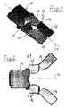
- FIG. 1 shows part of a patient support surface or operating table top with a base element 10, which is usually connected to or connectable to the column head of the support column of an operating table.
- a leg plate assembly 12 comprising two leg plates 14.
- Each leg plate 14 has a thigh pad 16 and a lower leg pad 18.
- the thigh pads 16 are connected by joints to the base member 10 and the lower leg pads 18 are connected by hinges to the respective thigh pad 16 so that the thigh pads 16 and lower leg pads 18 are adjusted to different positions can.
- Figure 1 shows the leg plates 12 and their parts 16, 18 in a basic position in which the leg plates 12 are directed parallel to the longitudinal central axis 20 of the operating table top and lie close to each other.
- FIG. 2 shows the arrangement according to FIG.
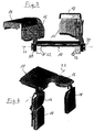
- FIG. 3 shows a position in which the thigh supports 16 of both leg plates 14 are folded vertically upwards about a horizontal folding axis 22, the thigh support 16 left in FIG. 3 being displaced outwards in the direction of the arrow B at the same time.
- the lower leg supports 18 of both leg plates 14 are each folded around a horizontal folding axis relative to the respective thigh support 16 in the horizontal position, wherein the left lower leg support 18 in FIG. 3 is additionally pivoted outwards about its expansion axis.
- FIG. 4 shows a position in which the left leg plate in FIG. 4 is pivoted completely downwards about the horizontal folding axis 22, whereas on the right leg plate 14 only the lower leg rest 18 is folded down vertically.
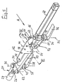
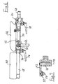
- Figure 5 can be seen a generally designated 24 fitting with a yoke 26 and a rigidly connected to this pin 28.
- the connector 24 can be inserted into a receptacle 30 which hinged about the horizontal folding axis 22 to the base member 10 pivotally is.
- the receptacle 30 can be tightened by a non-illustrated, because known clamping mechanism 32 in a desired pivotal position about the axis 22.
- the fitting 24 can be anchored in the receptacle 30 in a manner not shown.
- the hinged joint with the folding axis 22 could also be integrated into the connecting piece 24.
- a first link 34 is pivotally mounted about a pivot axis 36 and can be fixed by means of a known eccentric clamping mechanism 37 with a clamping lever 38 and toothed discs 40 in a desired pivotal position about the axis 36.
- the link 34 is pivotally connected at its other end with a link 42 about a hinge axis 44.
- the link 42 is plate-shaped and serves to hold a thigh plate 46 which can be fastened to the link 42 by means of screws 42 passing through the link 42 in holes 48 passing through them.
- the link 42 and the thigh plate 46 together form the thigh pad 16.
- the yoke 26 and the link 42 are also connected to each other via a second link 50, which is pivotally connected at one end to the yoke 26 about an axis 52 and with its other End is hinged to the link 42 about an axis 54 pivotally.
- the two links 34 and 50 form with their joint axes 36, 52 and 44, 54 a parallelogram joint, through which the link 42 and with him the thigh plate 46 can be adjusted parallel to itself, without changing its orientation in space.
- an articulated arm 56 is pivotally mounted in a hinged joint 58 about a horizontal folding axis 60.
- the articulated arm 56 can be fixed in any folding position by means of an eccentric tensioning mechanism 61, which can be operated via a tensioning lever 62.
- the eccentric clamping mechanism 61 is constructed in a similar manner as the clamping mechanism 37 intended for fixing the first link 34.
- the articulated arm 56 has a yoke 64 which forms an expansion joint 66 for a lower leg spar 68.
- the lower leg spar 68 serves to hold a lower leg plate 70.
- the spreading axis 72 of the expansion joint 66 is directed perpendicular to the folding axis 60 and to the level of the lower leg plate 70.
- the expansion joint 66 can be tensioned by means of an eccentric tensioning mechanism 74 be like the previously mentioned tensioning mechanisms comprises a clamping lever 76 and pulleys 78.
- the respective thigh rest 16 or the leg plate 14 as a whole can be pivoted relative to the base element 10 first around the pivot axis 22 upwards and downwards. Furthermore, the thigh rest 16 or the leg plate 14 as a whole can be displaced laterally relative to the base element 10 with the aid of the parallelogram joint 34, 40, 36, 52, 44, 54, as shown in FIG.
- the lower leg support 18 can be pivoted relative to the thigh support 16 on the one hand around the horizontal folding axis 60 (FIGS. 3 and 4) and on the other hand can be rotated about the expansion axis 72 (FIG. 2). Due to the fact that the thigh support 18 is adjusted by means of the parallelogram joint, the two folding axes 22 and 60 always remain parallel and horizontal.
Landscapes
- Health & Medical Sciences (AREA)
- Engineering & Computer Science (AREA)
- Biomedical Technology (AREA)
- Life Sciences & Earth Sciences (AREA)
- Animal Behavior & Ethology (AREA)
- General Health & Medical Sciences (AREA)
- Public Health (AREA)
- Veterinary Medicine (AREA)
- Accommodation For Nursing Or Treatment Tables (AREA)
- Rehabilitation Tools (AREA)
- Switches With Compound Operations (AREA)
- Valve-Gear Or Valve Arrangements (AREA)
Description
- Die Erfindung betrifft eine Beinplattenanordnung für OP-Tische nach dem Oberbegriff von Anspruch 1, wie sie aus DE-C-44 06 553 bekannt ist. Die Beinplattenanordnung umfasst zwei Beinplatten, die mit einem Basiselement einer OP-Tischplatte derart verbunden sind, daß sie zwischen einer Grundstellung, in der sie parallel zur Längsmittelachse der OP-Tischplatte dicht beieinander liegen und einer Spreizstellung verstellbar sind, in der sie einen Abstand von der Längsmittelachse haben.
- Bei allen Operationstechniken, bei denen der Operateur fußseits an das Operationsfeld herantritt, müssen die Beine des auf dem Operationstisch liegenden Patienten ausgespreizt werden. Bei den herkömmlichen Operationstischen sind die Beinplatten in einem Spreizgelenk mit senkrecht zur OP-Tischplatte gerichteter Achse schwenkbar an dem Basiselement angelenkt, so daß die Beinplatten um das hüftnahe Spreizgelenk ausgeschwenkt werden können und ein Freiraum im Mittenbereich zwischen den Beinplatten entsteht. Obwohl in der Regel an den einander zugekehrten Rändern der Beinplatte nahe dem Basiselement Aussparungen vorgesehen sind, ist der beim Ausschwenken der Beinplatten entstehende Freiraum nicht für alle Anwendungen ausreichend.
- Der Erfindung liegt die Aufgabe zugrunde, eine Beinplattenanordnung der eingangs genannten Art anzugeben, bei der ein hinreichender Freiraum zwischen den Beinplatten geschaffen werden kann.
- Diese Aufgabe wird bei einer gattungsgemäßen Beinplattenanordnung erfindungsgemäß durch die im kennzeichnender Teil von Anspruch 1 angegebenen Merkmale gelöst.
- Bei der erfindungsgemäßen Lösung wird die jeweilige Beinplatte durch das Parallelogrammgelenk parallel zu sich selbst seitlich nach außen versetzt. Dadurch entsteht zwischen den Beinplatten ein wesentlich größerer Freiraum, als dies bei einer gleichen Spreizung der Patientenbeine mit den herkömmlichen Beinplatten möglich wäre, die um ein hüftnahes Spreizgelenk verschwenkt werden.
- Bei vielen Anwendungen müssen nicht nur die Beine des Patienten ausgespreizt sondern auch die Unterschenkel gebeugt werden. Hierzu sind Beinplattenanordnungen bekannt, bei denen jede Beinplatte eine Oberschenkelauflage und eine Unterschenkelbauflage umfaßt, die jeweils in einem Klappgelenk um eine horizontale Achse relativ zum Basiselement bzw. relativ zueinander verschwenkbar sind, wie dies beispielsweise die US 6,276,012 B2 zeigt. Für eine solche Beinplattenanordnung wird erfindungsgemäß vorgeschlagen, daß die jeweilige Oberschenkelauflage über zwei das Parallelogrammgelenk bildende Lenker mit einem Anschlußstück verbunden ist, an dem erste Enden der Lenker angelenkt sind und das mit dem Basiselement um die Klappachse für die Oberschenkelauflage schwenkbar verbindbar ist, und daß die zweiten Enden der Lenker an der Oberschenkelauflage angelenkt sind, an der das Klappgelenk für die Unterschenkelauflage ausgebildet ist.
- Die erfindungsgemäße Lösung hat den Vorteil, daß sowohl die Klappachse für die Oberschenkelauflage als auch die Klappachse für die Unterschenkelauflage ihre Richtung im Raum beibehalten, wenn die Beinplatten voneinander weg bzw. aufeinander zu bewegt werden. Dadurch ist sichergestellt, daß die Unterschenkelauflage beim Anwinkeln der Beinplatte, d.h. beim Hochschwenken der Oberschenkelauflage und dem Abklappen der Unterschenkelauflage, diese nicht schräggestellt wird. Damit wird verhindert, daß der Unterschenkel seitlich von der Unterschenkelauflage abgleiten kann.
- Bei einer bevorzugten Ausführungsform ist die Oberschenkelauflage nicht einstückig ausgebildet sondern umfaßt ein Bindeglied und eine mit diesem lösbar verbindbare Oberschenkelplatte, wobei an dem Bindeglied die Lenker angelenkt sind und das Klappgelenk für die Unterschenkelplatte ausgebildet ist. Auch die Unterschenkelauflage umfaßt vorzugsweise einen Unterschenkelholm und eine lösbar mit diesem verbindbare Unterschenkelplatte. Das Bindeglied mit den Lenkern des Parallelogrammgelenkes und der Unterschenkelholm bilden somit eine Trägerstruktur der Beinplatte für die Oberschenkelplatte und die Unterschenkelplatte, die bei Bedarf ausgewechselt werden können.
- Um den Raum zwischen den Beinplatten weiter öffnen zu können, ist es zweckmäßig, wenn der Unterschenkelholm über ein Spreizgelenk mit einem Gelenkarm verbunden ist, der mit dem Bindeglied über das Klappgelenk für die Unterschenkelauflage verbunden ist, wobei die Achse des Spreizgelenkes senkrecht zur Achse des Klappgelenkes und senkrecht zur Ebene der Unterschenkelplatte gerichtet ist. Die Reihenfolge der Gelenkanordnung - von dem Basiselement zur Unterschenkelauflage hin betrachtet - in Verbindung mit der Parallelführung der Oberschenkelauflage stellt sicher, daß die Unterschenkelplatte auch bei geschwenkter und ausgespreizter Oberschenkelplatte immer um eine waagerechte Klappachse schwenkt und somit ein Abkippen der Unterschenkelplatte um eine Längsachse ausgeschlossen ist.
- Vorzugsweise ist das Anschlußstück in eine operationstischfeste Aufnahme einsteckbar, die Teil des Klappgelenkes für die Oberschenkelauflage ist. Damit kann die Beinplatte schnell und einfach mit dem Basiselement verbunden oder von diesem gelöst werden und gegebenenfalls durch eine andere Beinplatte ersetzt werden.
- Die folgende Beschreibung erläutert in Verbindung mit den beigefügten Zeichnungen die Erfindung anhand eines Ausführungsbeispiels. Es zeigen:
- Figur 1
- eine perspektivische Ansicht schräg von oben auf eine mit einem Basiselement einer Operationstischplatte verbundene Beinplattenanordnung mit den Beinplatten in geschlossener Stellung,
- Figur 2
- eine Draufsicht auf die Anordnung gemäß Figur 1 mit den Beinplatten in gespreizter Stellung,
- Figur 3
- eine Ansicht der Beinplattenanordnung vom Fußende aus mit angewinkelten Beinplatten,
- Figur 4
- eine perspektivische Ansicht der in Figur 1 dargestellten Anordnung mit einer vollständig nach unten geschwenkten Beinplatte und einer nach unten geklappten Unterschenkelauflage,
- Figur 5
- eine perspektivische Darstellung der Trägerstruktur einer Beinplatte,
- Figur 6
- eine Seitenansicht der in Figur 5 dargestellten Struktur in Richtung des Pfeiles A in Figur 5 mit montierten Platten und
- Figur 7
- einen Schnitt durch die Trägerstruktur entlang der Linie VII-VII in Figur 5.
- In Figur 1 ist ein Teil einer Patientenlagerfläche oder Operationstischplatte dargestellt mit einem Basiselement 10, das üblicherweise mit dem Säulenkopf der Tragsäule eines Operationstisches verbunden oder mit diesem verbindbar ist. Mit dem Basiselement 10 ist eine Beinplattenanordnung 12 verbunden, die zwei Beinplatten 14 umfaßt. Jede Beinplatte 14 hat eine Oberschenkelauflage 16 und eine Unterschenkelauflage 18. Die Oberschenkelauflagen 16 sind über Gelenke mit dem Basiselement 10 und die Unterschenkelauflagen 18 sind über Gelenke mit der jeweiligen Oberschenkelauflage 16 verbunden, so daß die Oberschenkelauflagen 16 und die Unterschenkelbauflagen 18 in unterschiedliche Stellungen verstellt werden können. Figur 1 zeigt die Beinplatten 12 und deren Teile 16, 18 in einer Grundstellung, in der die Beinplatten 12 parallel zur Längsmittelachse 20 der Operationstischplatte gerichtet sind und dicht beieinander liegen. Figur 2 zeigt die Anordnung gemäß Figur 1 in einer Spreizstellung, in der die Oberschenkelauflagen 16 in Richtung der Pfeile B parallel zu sich selbst nach außen verschoben sind, während die Unterschenkelauflagen 18 an den jeweiligen Oberschenkelauflagen 16 um eine zur Bildebene senkrechte Spreizachse in Richtung der Pfeile C nach außen verschwenkt sind.
- Figur 3 zeigt eine Stellung, in welcher die Oberschenkelauflagen 16 beider Beinplatten 14 um eine horizontale Klappachse 22 senkrecht nach oben geklappt sind, wobei die in der Figur 3 linke Oberschenkelauflage 16 gleichzeitig in Richtung des Pfeiles B nach außen verschoben ist. Die Unterschenkelauflagen 18 beider Beinplatten 14 sind jeweils um eine horizontale Klappachse gegenüber der jeweiligen Oberschenkelauflage 16 in die horizontale Lage geklappt, wobei die in der Figur 3 linke Unterschenkelauflage 18 zusätzlich um ihre Spreizachse nach außen geschwenkt ist.
- Figur 4 schließlich zeigt eine Stellung, bei welcher die in der Figur 4 linke Beinplatte vollständig um die horizontale Klappachse 22 nach unten geschwenkt ist, während an der rechten Beinplatte 14 lediglich die Unterschenkelauflage 18 senkrecht nach unten abgeklappt ist.
- Der Aufbau der Trägerstruktur der jeweiligen Beinplatte mit ihren Gelenken, welche die vorstehend dargestellten Bewegungen der Oberschenkelauflage und Unterschenkelauflage ermöglichen, soll nun anhand der Figuren 5 bis 7 erläutert werden.
- In Figur 5 erkennt man ein allgemein mit 24 bezeichnetes Anschlußstück mit einer Gelenkgabel 26 und einem mit dieser starr verbundenen Zapfen 28. Mit diesem Zapfen kann das Anschlußstück 24 in eine Aufnahme 30 gesteckt werden, die um die horizontale Klappachse 22 an dem Basiselement 10 schwenkbar angelenkt ist. Die Aufnahme 30 kann durch einen nicht näher dargestellten, weil an sich bekannten Spannmechanismus 32 in einer gewünschten Schwenkstellung um die Achse 22 festgespannt werden. Das Anschlußstück 24 kann in der Aufnahme 30 in nicht dargestellter Weise verankert werden. Das Klappgelenk mit der Klappachse 22 könnte auch in das Anschlußstück 24 integriert sein.
- In der Gelenkgabel 26 des Anschlußstückes 24 ist ein erster Lenker 34 um eine Schwenkachse 36 schwenkbar gelagert und kann mit Hilfe eines an sich bekannten Exzenterspannmechanismus 37 mit einem Spannhebel 38 und Zahnscheiben 40 in einer gewünschten Schwenkstellung um die Achse 36 fixiert werden. Der Lenker 34 ist an seinem anderen Ende mit einem Bindeglied 42 um eine Gelenkachse 44 schwenkbar verbunden. Das Bindeglied 42 ist plattenförmig und dient zur Halterung einer Oberschenkelplatte 46, die mit das Bindeglied 42 in Bohrungen 48 durchsetzenden nicht dargestellten Schrauben an dem Bindeglied 42 befestigt werden kann. Das Bindeglied 42 und die Oberschenkelplatte 46 bilden zusammen die Oberschenkelauflage 16. Die Gelenkgabel 26 und das Bindeglied 42 sind ferner über einen zweiten Lenker 50 miteinander verbunden, der mit seinem einen Ende an der Gelenkgabel 26 um eine Achse 52 schwenkbar angelenkt ist und mit seinem anderen Ende an dem Bindeglied 42 um eine Achse 54 schwenkbar angelenkt ist. Die beiden Lenker 34 und 50 bilden mit ihren Gelenkachsen 36, 52 und 44, 54 ein Parallelogrammgelenk, durch das das Bindeglied 42 und mit ihm die Oberschenkelplatte 46 parallel zu sich selbst verstellt werden kann, ohne daß sich seine Ausrichtung im Raum ändert.
- An dem dem Anschlussstück 24 fernen Ende des Bindegliedes 42 ist ein Gelenkarm 56 in einem Klappgelenk 58 um eine horizontale Klappachse 60 schwenkbar gelagert. Der Gelenkarm 56 kann mit Hilfe eines Exzenterspannmechanismus 61, der über einen Spannhebel 62 bedient werden kann, in einer beliebigen Klappstellung fixiert werden. Der Exzenterspannmechanismus 61 ist in ähnlicher Weise aufgebaut wie der zum Feststellen des ersten Lenkers 34 bestimmte Spannmechanismus 37.
- Der Gelenkarm 56 hat eine Gelenkgabel 64, die ein Spreizgelenk 66 für einen Unterschenkelholm 68 bildet. Der Unterschenkelholm 68 dient zur Halterung einer Unterschenkelplatte 70. Die Spreizachse 72 des Spreizgelenkes 66 ist senkrecht zur Klappachse 60 und zur Ebene der Unterschenkelplatte 70 gerichtet. Das Spreizgelenk 66 kann mittels eines Exzenterspannmechanismus 74 gespannt werden, der wie die vorher genannten Spannmechanismen einen Spannhebel 76 und Zahnscheiben 78 umfaßt.
- Die in den Figuren 5 bis 7 dargestellte Trägerstruktur wird durch die Oberschenkelplatte 46 und die Unterschenkelplatte 70 vervollständigt, wie dies in Figur 6 angedeutet ist.
- Die jeweilige -Oberschenkelauflage 16 oder die Beinplatte 14 als Ganzes kann gegenüber dem Basiselement 10 zunächst um die Klappachse 22 nach oben und unten verschwenkt werden. Femer kann die Oberschenkelauflage 16 bzw. die Beinplatte 14 als Ganzes mit Hilfe des Parallelogrammgelenkes 34, 40, 36, 52, 44, 54 seitlich gegenüber dem Basiselement 10 versetzt werden, wie dies in der Figur 2 dargestellt ist. Die Unterschenkelauflage 18 kann gegenüber der Oberschenkelauflage 16 einerseits um die horizontale Klappachse 60 geschwenkt (Figuren 3 und 4) und andererseits um die Spreizachse 72 gedreht werden (Figur 2). Aufgrund der Tatsache, daß die Oberschenkelauflage 18 mit Hilfe des Parallelogrammgelenkes verstellt wird, bleiben die beiden Klappachsen 22 und 60 stets parallel und horizontal. Dies hat zur Folge, daß die Unterschenkelauflage in allen ihren möglichen Stellungen bezüglich ihrer Längsmittelachse stabil bleibt, d.h. nicht seitlich gekippt wird. Damit wird vermieden, daß das Bein eines Patienten von der Unterschenkelauflage abrutschen kann, was zur Folge hätte, daß es zusätzlich fixiert werden müßte. Aus einem Vergleich der Figuren 1 und 2 erkennt man femer sofort, daß durch ein Ausschwenken der Beinplatten um eine an der Verbindungsstelle zwischen Basiselement 10 und Oberschenkelauflage 16 liegende vertikale Spreizachse nur ein vergleichsweise geringer Freiraum zwischen den beiden Beinplatten geschaffen werden kann, während die seitliche Verschiebung der Beinplatten mit Hilfe des jeweiligen Parallelogrammgelenkes einen großen Freiraum schafft.
Claims (5)
- Beinplattenanordnung für OP-Tische mit zwei Beinplatten (14), die mit einem Basiselement (10) einer OP-Tischplatte derart verbunden sind, daß sie zwischen einer Grundstellung, in der sie parallel zur Längsmittelachse (20) der OP-Tischplatte dicht beieinander liegen, und einer Spreizstellung verstellbar sind, in der sie einen Abstand von der Längsmittelachse (20) haben, wobei die die jeweilige Beinplatte (14) mit dem Basiselement (10) über ein Parallelogrammgelenk verbunden ist, dessen Gelenkachsen (36, 52, 44, 54) senkrecht zur Ebene des Basiselementes (10) gerichtet sind, dadurch gekennzeichnet, daß jede Beinplatte (14) eine Oberschenkelauflage (16) und eine Unterschenkelauflage (18) umfaßt, die jeweils in einem Klappgelenk um eine horizontale Achse (22; 60) relativ zum Basiselement (10) bzw. relativ zueinander verschwenkbar sind, daß die jeweilige Oberschenkelauflage (16) über zwei das Parallelogrammgelenk bildende Lenker (34, 50) mit einem Anschlußstück (24) verbunden ist, an dem erste Enden der Lenker (34, 50) angelenkt sind und das mit dem Basiselement (10) um die Klappachse (22) für die Oberschenkelauflage (16) schwenkbar verbindbar ist, und daß die zweiten Enden der Lenker (34, 50) an der Oberschenkelauflage (16) angelenkt sind, an der das Klappgelenk (58) für die Unterschenkelauflage (18) ausgebildet ist.
- Beinplattenanordnung nach Anspruch 1, dadurch gekennzeichnet, daß die Oberschenkelauflage (16) ein Bindeglied (42) und eine mit diesem lösbar verbindbare Oberschenkelplatte (46) umfaßt, wobei an dem Bindeglied (42) die Lenker (34, 50) angelenkt sind und das Klappgelenk (58) für die Unterschenkelauflage (18) ausgebildet ist.
- Beinplattenanordnung nach Anspruch 1 oder 2, dadurch gekennzeichnet, daß die Unterschenkelauflage (18) einen Unterschenkelholm (68) und eine lösbar mit dieser verbindbare Unterschenkelplatte (70) umfaßt.
- Beinplattenanordnung nach den Ansprüchen 2 und 3, dadurch gekennzeichnet, dass der Unterschenkelholm (68) über ein Spreizgelenk (66) mit einem Gelenkarm (56) verbunden ist, der mit dem Bindeglied (42) über das Klappgelenk (58) für die Unterschenkelauflage (18) verbunden ist, wobei die Achse (72) des Spreizgelenkes (66) senkrecht zur Achse (60) des Klappgelenkes (58) für die Unterschenkelauflage (18) und senkrecht zur Ebene der Unterschenkelplatte (70) gerichtet ist.
- Beinplattenanordnung nach einem der Ansprüche 1 bis 4, dadurch gekennzeichnet, dass das Anschlussstück (24) in eine operationstischfeste Aufnahme (30) einsteckbar ist, die Teil des Klappgelenkes für die Oberschenkelauflage (16) ist.
Applications Claiming Priority (3)
| Application Number | Priority Date | Filing Date | Title |
|---|---|---|---|
| DE10253906A DE10253906A1 (de) | 2002-11-19 | 2002-11-19 | Beinplattenanordnung für Operationstische |
| DE10253906 | 2002-11-19 | ||
| PCT/EP2003/010844 WO2004045482A1 (de) | 2002-11-19 | 2003-09-30 | Beinplattenanordnung für operationstische |
Publications (2)
| Publication Number | Publication Date |
|---|---|
| EP1565143A1 EP1565143A1 (de) | 2005-08-24 |
| EP1565143B1 true EP1565143B1 (de) | 2006-04-26 |
Family
ID=32240168
Family Applications (1)
| Application Number | Title | Priority Date | Filing Date |
|---|---|---|---|
| EP03811345A Expired - Lifetime EP1565143B1 (de) | 2002-11-19 | 2003-09-30 | Beinplattenanordnung für operationstische |
Country Status (7)
| Country | Link |
|---|---|
| US (1) | US7454806B2 (de) |
| EP (1) | EP1565143B1 (de) |
| JP (1) | JP4383351B2 (de) |
| AT (1) | ATE324095T1 (de) |
| DE (2) | DE10253906A1 (de) |
| ES (1) | ES2263069T3 (de) |
| WO (1) | WO2004045482A1 (de) |
Cited By (1)
| Publication number | Priority date | Publication date | Assignee | Title |
|---|---|---|---|---|
| US8615827B2 (en) | 2009-03-03 | 2013-12-31 | Hill-Rom Services, Inc. | Person-support apparatus with movable portions |
Families Citing this family (27)
| Publication number | Priority date | Publication date | Assignee | Title |
|---|---|---|---|---|
| DE602005009131D1 (de) * | 2005-02-18 | 2008-10-02 | Tonijoan Jaume Farre | Einstellbare Liege für Massagetherapie |
| DE102005053753A1 (de) | 2005-11-10 | 2007-05-16 | Maquet Gmbh & Co Kg | Hydraulische Säulenklemmung |
| DE102005053755A1 (de) | 2005-11-10 | 2007-05-16 | Maquet Gmbh & Co Kg | Polsterelement für eine Patientenliegefläche eines Operationstisches |
| DE102005053754A1 (de) * | 2005-11-10 | 2007-05-16 | Maquet Gmbh & Co Kg | Einrichtung zum Verstellen der Liegefläche eines Operationstisches |
| DE102005054174A1 (de) | 2005-11-14 | 2007-05-16 | Maquet Gmbh & Co Kg | Patientenlagerfläche für einen Operationstisch |
| DE102005054230A1 (de) | 2005-11-14 | 2007-05-24 | Maquet Gmbh & Co. Kg | Verfahren und Einrichtung zur bidirektionalen IR-Datenübertragung zwischen einem Operationstisch und einem Bediengerät |
| DE102005054223A1 (de) | 2005-11-14 | 2007-05-16 | Maquet Gmbh & Co Kg | Einrichtung zum Verstellen eines Operationstisches |
| DE102005054221A1 (de) | 2005-11-14 | 2007-05-16 | Maquet Gmbh & Co Kg | Patientenlagersystem |
| DE102005054175A1 (de) * | 2005-11-14 | 2007-05-16 | Maquet Gmbh & Co Kg | Gelenkanordnung zur Verbindung zweier Segmente einer Patientenlagerfläche |
| DE102005054222A1 (de) | 2005-11-14 | 2007-05-16 | Maquet Gmbh & Co Kg | Operationstisch |
| DE102005054220B4 (de) | 2005-11-14 | 2024-12-05 | MAQUET GmbH | Patientenlagersystem |
| DE102006011723B3 (de) | 2006-03-14 | 2007-08-23 | Siemens Ag | Adaptionsverfahren für Streuungen in zylinderselektiven Einspritzmengen einer Direkteinspritzanlage und Verfahren zur zylinderselektiven Einspritzsteuerung |
| US7896442B2 (en) * | 2008-05-30 | 2011-03-01 | White William L | Method and apparatus to ingress and egress of chair |
| GB2460863B (en) * | 2008-06-12 | 2012-10-03 | Eschmann Holdings Ltd | Articulated leg section |
| EP2210526A1 (de) * | 2009-01-27 | 2010-07-28 | Pro-Cord S.p.A. | In eine Chaiselongue konvertierbarer Sessel |
| US8041008B2 (en) | 2009-01-29 | 2011-10-18 | The Invention Science Fund I, Llc | Diagnostic delivery service |
| US8130904B2 (en) | 2009-01-29 | 2012-03-06 | The Invention Science Fund I, Llc | Diagnostic delivery service |
| GB201116611D0 (en) | 2011-09-27 | 2011-11-09 | Provost Fellows Foundation Scholars And The Other Members Of Board Of College Of The Holy Undivided | A limb therapy device |
| DE102011115097A1 (de) * | 2011-10-07 | 2013-04-11 | Gharieni Gmbh | Behandlungsliege |
| GB2498562B (en) * | 2012-01-20 | 2013-12-04 | Eschmann Holdings Ltd | Leg support for a surgical table |
| US9107792B2 (en) | 2012-09-07 | 2015-08-18 | Allen Medical Systems, Inc. | Carriage for a surgical boot of a hip distractor |
| US9730851B2 (en) | 2012-09-07 | 2017-08-15 | Allen Medical Systems, Inc. | Surgical support system |
| US9211099B2 (en) * | 2013-02-07 | 2015-12-15 | G2 Medical, Llc | Radial access methods and apparatus |
| DE102016113250A1 (de) | 2015-07-24 | 2017-01-26 | MAQUET GmbH | Verstellvorrichtung zum Positionieren von Lagerflächensegmenten eines Operationstisches |
| US10857052B1 (en) * | 2016-08-31 | 2020-12-08 | Pivotal Health Solutions, Inc. | Treatment table for therapeutic treatment, physical rehabilitation and training and method of use |
| CN112137822A (zh) * | 2020-10-14 | 2020-12-29 | 上海市同济医院 | 一种妇产科盆底检查辅助装置 |
| CN114376844B (zh) * | 2022-01-18 | 2022-10-04 | 嘉兴市第二医院 | 一种截石位手术床 |
Family Cites Families (5)
| Publication number | Priority date | Publication date | Assignee | Title |
|---|---|---|---|---|
| US5157800A (en) * | 1991-04-15 | 1992-10-27 | Hill-Rom Company, Inc. | Foot section for birthing bed |
| DE4406553C1 (de) * | 1994-03-01 | 1995-07-20 | Stierlen Maquet Ag | Anlenkung zweier Beinplatten an der Rumpfplatte eines Operationstisches |
| US5645079A (en) * | 1994-12-02 | 1997-07-08 | Zahiri; Hormoz | Apparatus for mechanically holding, maneuvering and maintaining a body part of a patient during orthopedic surgery |
| EP1028685B1 (de) * | 1997-11-07 | 2005-04-06 | Hill-Rom Services, Inc. | Operationstischvorrichtung |
| US6378149B1 (en) * | 1999-01-25 | 2002-04-30 | Steris Inc | Radiolucent split-leg accessory for a surgical table |
-
2002
- 2002-11-19 DE DE10253906A patent/DE10253906A1/de not_active Withdrawn
-
2003
- 2003-09-30 JP JP2004552468A patent/JP4383351B2/ja not_active Expired - Fee Related
- 2003-09-30 US US10/534,429 patent/US7454806B2/en not_active Expired - Lifetime
- 2003-09-30 WO PCT/EP2003/010844 patent/WO2004045482A1/de not_active Ceased
- 2003-09-30 ES ES03811345T patent/ES2263069T3/es not_active Expired - Lifetime
- 2003-09-30 DE DE50303139T patent/DE50303139D1/de not_active Expired - Lifetime
- 2003-09-30 AT AT03811345T patent/ATE324095T1/de not_active IP Right Cessation
- 2003-09-30 EP EP03811345A patent/EP1565143B1/de not_active Expired - Lifetime
Cited By (1)
| Publication number | Priority date | Publication date | Assignee | Title |
|---|---|---|---|---|
| US8615827B2 (en) | 2009-03-03 | 2013-12-31 | Hill-Rom Services, Inc. | Person-support apparatus with movable portions |
Also Published As
| Publication number | Publication date |
|---|---|
| EP1565143A1 (de) | 2005-08-24 |
| US7454806B2 (en) | 2008-11-25 |
| US20060042011A1 (en) | 2006-03-02 |
| JP2006507048A (ja) | 2006-03-02 |
| DE10253906A1 (de) | 2004-06-03 |
| DE50303139D1 (de) | 2006-06-01 |
| ES2263069T3 (es) | 2006-12-01 |
| WO2004045482A1 (de) | 2004-06-03 |
| ATE324095T1 (de) | 2006-05-15 |
| JP4383351B2 (ja) | 2009-12-16 |
Similar Documents
| Publication | Publication Date | Title |
|---|---|---|
| EP1565143A1 (de) | Beinplattenanordnung für operationstische | |
| DE69733577T2 (de) | Rippenretraktor | |
| DE112005000409T5 (de) | Gelenkscharnier | |
| DE4418357A1 (de) | Innenrückblickspiegel für Fahrzeuge | |
| EP1658016B1 (de) | Chirurgische haltevorrichtung | |
| DE19837987C2 (de) | Tisch | |
| DE3130444C2 (de) | Fahrzeugsitz | |
| DE3505528C2 (de) | ||
| EP1579812A1 (de) | Vorrichtung zum Setzen eines Schnittblocks für eine Resektion der Tibia | |
| DE3834358C1 (en) | Rib retractor for thoracic, pulmonary and cardiac surgery | |
| EP1569567B1 (de) | Führungseinrichtung für ein chirurgisches bearbeitungswerkzeug | |
| DE69413075T2 (de) | Sitz- und Bettrahmen in Beziehung auf die variabel zu platzierende Rückenlehne rotierbar | |
| DE29711401U1 (de) | Stütz- und Ablagevorrichtung | |
| EP0178569A2 (de) | Arbeitstisch, insbesondere Bürotisch | |
| DE8806231U1 (de) | Doppelgelenkschiene zur Behandlung nach Operationen am Knie | |
| DE2802177C2 (de) | Klappbarer Wandtisch | |
| DE2415572B2 (de) | Möbel-, insbesondere Tischgestell | |
| DE3872193T2 (de) | Abkantbank. | |
| DE10332403A1 (de) | Flächenreinigungsgerät | |
| DE3501963A1 (de) | Beinbewegungsschiene | |
| DE19741996B4 (de) | Kraftfahrzeugsitz mit einem Sitzträger und einer Rückenlehne | |
| WO1996029910A1 (de) | Vorrichtung zur verstellung der höhe und/oder neigung der tischplatte eines tisches | |
| DE202021101342U1 (de) | Tisch | |
| DE8501550U1 (de) | Beinbewegungsschiene | |
| DE20006871U1 (de) | Verstellbare schiefe Ebene, insbesondere für Betten |
Legal Events
| Date | Code | Title | Description |
|---|---|---|---|
| PUAI | Public reference made under article 153(3) epc to a published international application that has entered the european phase |
Free format text: ORIGINAL CODE: 0009012 |
|
| 17P | Request for examination filed |
Effective date: 20050606 |
|
| AK | Designated contracting states |
Kind code of ref document: A1 Designated state(s): AT BE BG CH CY CZ DE DK EE ES FI FR GB GR HU IE IT LI LU MC NL PT RO SE SI SK TR |
|
| GRAP | Despatch of communication of intention to grant a patent |
Free format text: ORIGINAL CODE: EPIDOSNIGR1 |
|
| GRAS | Grant fee paid |
Free format text: ORIGINAL CODE: EPIDOSNIGR3 |
|
| GRAA | (expected) grant |
Free format text: ORIGINAL CODE: 0009210 |
|
| AK | Designated contracting states |
Kind code of ref document: B1 Designated state(s): AT BE BG CH CY CZ DE DK EE ES FI FR GB GR HU IE IT LI LU MC NL PT RO SE SI SK TR |
|
| PG25 | Lapsed in a contracting state [announced via postgrant information from national office to epo] |
Ref country code: RO Free format text: LAPSE BECAUSE OF FAILURE TO SUBMIT A TRANSLATION OF THE DESCRIPTION OR TO PAY THE FEE WITHIN THE PRESCRIBED TIME-LIMIT Effective date: 20060426 Ref country code: SI Free format text: LAPSE BECAUSE OF FAILURE TO SUBMIT A TRANSLATION OF THE DESCRIPTION OR TO PAY THE FEE WITHIN THE PRESCRIBED TIME-LIMIT Effective date: 20060426 Ref country code: NL Free format text: LAPSE BECAUSE OF FAILURE TO SUBMIT A TRANSLATION OF THE DESCRIPTION OR TO PAY THE FEE WITHIN THE PRESCRIBED TIME-LIMIT Effective date: 20060426 Ref country code: SK Free format text: LAPSE BECAUSE OF FAILURE TO SUBMIT A TRANSLATION OF THE DESCRIPTION OR TO PAY THE FEE WITHIN THE PRESCRIBED TIME-LIMIT Effective date: 20060426 Ref country code: CZ Free format text: LAPSE BECAUSE OF FAILURE TO SUBMIT A TRANSLATION OF THE DESCRIPTION OR TO PAY THE FEE WITHIN THE PRESCRIBED TIME-LIMIT Effective date: 20060426 Ref country code: FI Free format text: LAPSE BECAUSE OF FAILURE TO SUBMIT A TRANSLATION OF THE DESCRIPTION OR TO PAY THE FEE WITHIN THE PRESCRIBED TIME-LIMIT Effective date: 20060426 Ref country code: IE Free format text: LAPSE BECAUSE OF FAILURE TO SUBMIT A TRANSLATION OF THE DESCRIPTION OR TO PAY THE FEE WITHIN THE PRESCRIBED TIME-LIMIT Effective date: 20060426 |
|
| REG | Reference to a national code |
Ref country code: GB Ref legal event code: FG4D Free format text: NOT ENGLISH |
|
| REG | Reference to a national code |
Ref country code: CH Ref legal event code: NV Representative=s name: SCHNEIDER FELDMANN AG PATENT- UND MARKENANWAELTE |
|
| GBT | Gb: translation of ep patent filed (gb section 77(6)(a)/1977) |
Effective date: 20060426 |
|
| REG | Reference to a national code |
Ref country code: IE Ref legal event code: FG4D Free format text: LANGUAGE OF EP DOCUMENT: GERMAN |
|
| REF | Corresponds to: |
Ref document number: 50303139 Country of ref document: DE Date of ref document: 20060601 Kind code of ref document: P |
|
| REG | Reference to a national code |
Ref country code: SE Ref legal event code: TRGR |
|
| PG25 | Lapsed in a contracting state [announced via postgrant information from national office to epo] |
Ref country code: DK Free format text: LAPSE BECAUSE OF FAILURE TO SUBMIT A TRANSLATION OF THE DESCRIPTION OR TO PAY THE FEE WITHIN THE PRESCRIBED TIME-LIMIT Effective date: 20060726 |
|
| PG25 | Lapsed in a contracting state [announced via postgrant information from national office to epo] |
Ref country code: PT Free format text: LAPSE BECAUSE OF FAILURE TO SUBMIT A TRANSLATION OF THE DESCRIPTION OR TO PAY THE FEE WITHIN THE PRESCRIBED TIME-LIMIT Effective date: 20060926 |
|
| PG25 | Lapsed in a contracting state [announced via postgrant information from national office to epo] |
Ref country code: MC Free format text: LAPSE BECAUSE OF NON-PAYMENT OF DUE FEES Effective date: 20060930 Ref country code: BE Free format text: LAPSE BECAUSE OF NON-PAYMENT OF DUE FEES Effective date: 20060930 |
|
| NLV1 | Nl: lapsed or annulled due to failure to fulfill the requirements of art. 29p and 29m of the patents act | ||
| REG | Reference to a national code |
Ref country code: IE Ref legal event code: FD4D |
|
| ET | Fr: translation filed | ||
| REG | Reference to a national code |
Ref country code: ES Ref legal event code: FG2A Ref document number: 2263069 Country of ref document: ES Kind code of ref document: T3 |
|
| PLBE | No opposition filed within time limit |
Free format text: ORIGINAL CODE: 0009261 |
|
| STAA | Information on the status of an ep patent application or granted ep patent |
Free format text: STATUS: NO OPPOSITION FILED WITHIN TIME LIMIT |
|
| 26N | No opposition filed |
Effective date: 20070129 |
|
| BERE | Be: lapsed |
Owner name: MAQUET G.M.B.H. & CO. KG Effective date: 20060930 |
|
| PG25 | Lapsed in a contracting state [announced via postgrant information from national office to epo] |
Ref country code: GR Free format text: LAPSE BECAUSE OF FAILURE TO SUBMIT A TRANSLATION OF THE DESCRIPTION OR TO PAY THE FEE WITHIN THE PRESCRIBED TIME-LIMIT Effective date: 20060727 |
|
| PG25 | Lapsed in a contracting state [announced via postgrant information from national office to epo] |
Ref country code: EE Free format text: LAPSE BECAUSE OF FAILURE TO SUBMIT A TRANSLATION OF THE DESCRIPTION OR TO PAY THE FEE WITHIN THE PRESCRIBED TIME-LIMIT Effective date: 20060426 Ref country code: BG Free format text: LAPSE BECAUSE OF FAILURE TO SUBMIT A TRANSLATION OF THE DESCRIPTION OR TO PAY THE FEE WITHIN THE PRESCRIBED TIME-LIMIT Effective date: 20060726 |
|
| PG25 | Lapsed in a contracting state [announced via postgrant information from national office to epo] |
Ref country code: LU Free format text: LAPSE BECAUSE OF NON-PAYMENT OF DUE FEES Effective date: 20060930 Ref country code: TR Free format text: LAPSE BECAUSE OF FAILURE TO SUBMIT A TRANSLATION OF THE DESCRIPTION OR TO PAY THE FEE WITHIN THE PRESCRIBED TIME-LIMIT Effective date: 20060426 Ref country code: HU Free format text: LAPSE BECAUSE OF FAILURE TO SUBMIT A TRANSLATION OF THE DESCRIPTION OR TO PAY THE FEE WITHIN THE PRESCRIBED TIME-LIMIT Effective date: 20061027 |
|
| PG25 | Lapsed in a contracting state [announced via postgrant information from national office to epo] |
Ref country code: CY Free format text: LAPSE BECAUSE OF FAILURE TO SUBMIT A TRANSLATION OF THE DESCRIPTION OR TO PAY THE FEE WITHIN THE PRESCRIBED TIME-LIMIT Effective date: 20060426 |
|
| PGFP | Annual fee paid to national office [announced via postgrant information from national office to epo] |
Ref country code: AT Payment date: 20090921 Year of fee payment: 7 Ref country code: SE Payment date: 20090922 Year of fee payment: 7 |
|
| PG25 | Lapsed in a contracting state [announced via postgrant information from national office to epo] |
Ref country code: AT Free format text: LAPSE BECAUSE OF NON-PAYMENT OF DUE FEES Effective date: 20100930 |
|
| PG25 | Lapsed in a contracting state [announced via postgrant information from national office to epo] |
Ref country code: SE Free format text: LAPSE BECAUSE OF NON-PAYMENT OF DUE FEES Effective date: 20101001 |
|
| REG | Reference to a national code |
Ref country code: DE Ref legal event code: R082 Ref document number: 50303139 Country of ref document: DE Representative=s name: PATENTANWAELTE SCHAUMBURG, THOENES, THURN, LAN, DE |
|
| REG | Reference to a national code |
Ref country code: DE Ref legal event code: R082 Ref document number: 50303139 Country of ref document: DE Representative=s name: PATENTANWAELTE SCHAUMBURG, THOENES, THURN, LAN, DE Effective date: 20141210 Ref country code: DE Ref legal event code: R081 Ref document number: 50303139 Country of ref document: DE Owner name: MAQUET GMBH, DE Free format text: FORMER OWNER: MAQUET GMBH & CO. KG, 76437 RASTATT, DE Effective date: 20141210 Ref country code: DE Ref legal event code: R082 Ref document number: 50303139 Country of ref document: DE Representative=s name: SCHAUMBURG & PARTNER PATENTANWAELTE GBR, DE Effective date: 20141210 Ref country code: DE Ref legal event code: R082 Ref document number: 50303139 Country of ref document: DE Representative=s name: ZACCO DR. PETERS UND PARTNER, DE Effective date: 20141210 Ref country code: DE Ref legal event code: R082 Ref document number: 50303139 Country of ref document: DE Representative=s name: ZACCO PATENTANWALTS- UND RECHTSANWALTSGESELLSC, DE Effective date: 20141210 |
|
| REG | Reference to a national code |
Ref country code: DE Ref legal event code: R082 Ref document number: 50303139 Country of ref document: DE Representative=s name: SCHAUMBURG & PARTNER PATENTANWAELTE GBR, DE Ref country code: DE Ref legal event code: R082 Ref document number: 50303139 Country of ref document: DE Representative=s name: ZACCO DR. PETERS UND PARTNER, DE Ref country code: DE Ref legal event code: R082 Ref document number: 50303139 Country of ref document: DE Representative=s name: ZACCO PATENTANWALTS- UND RECHTSANWALTSGESELLSC, DE |
|
| REG | Reference to a national code |
Ref country code: DE Ref legal event code: R082 Ref document number: 50303139 Country of ref document: DE Representative=s name: ZACCO DR. PETERS UND PARTNER, DE Ref country code: DE Ref legal event code: R082 Ref document number: 50303139 Country of ref document: DE Representative=s name: ZACCO PATENTANWALTS- UND RECHTSANWALTSGESELLSC, DE |
|
| REG | Reference to a national code |
Ref country code: FR Ref legal event code: PLFP Year of fee payment: 13 |
|
| REG | Reference to a national code |
Ref country code: FR Ref legal event code: PLFP Year of fee payment: 14 |
|
| REG | Reference to a national code |
Ref country code: FR Ref legal event code: PLFP Year of fee payment: 15 |
|
| REG | Reference to a national code |
Ref country code: FR Ref legal event code: PLFP Year of fee payment: 16 |
|
| REG | Reference to a national code |
Ref country code: CH Ref legal event code: PFA Owner name: MAQUET GMBH AND CO. KG, DE Free format text: FORMER OWNER: MAQUET GMBH AND CO. KG, DE |
|
| PGFP | Annual fee paid to national office [announced via postgrant information from national office to epo] |
Ref country code: DE Payment date: 20200812 Year of fee payment: 18 Ref country code: GB Payment date: 20200828 Year of fee payment: 18 Ref country code: FR Payment date: 20200814 Year of fee payment: 18 |
|
| PGFP | Annual fee paid to national office [announced via postgrant information from national office to epo] |
Ref country code: CH Payment date: 20200818 Year of fee payment: 18 Ref country code: IT Payment date: 20200921 Year of fee payment: 18 |
|
| PGFP | Annual fee paid to national office [announced via postgrant information from national office to epo] |
Ref country code: ES Payment date: 20201001 Year of fee payment: 18 |
|
| REG | Reference to a national code |
Ref country code: DE Ref legal event code: R119 Ref document number: 50303139 Country of ref document: DE |
|
| REG | Reference to a national code |
Ref country code: CH Ref legal event code: PL |
|
| GBPC | Gb: european patent ceased through non-payment of renewal fee |
Effective date: 20210930 |
|
| PG25 | Lapsed in a contracting state [announced via postgrant information from national office to epo] |
Ref country code: GB Free format text: LAPSE BECAUSE OF NON-PAYMENT OF DUE FEES Effective date: 20210930 Ref country code: FR Free format text: LAPSE BECAUSE OF NON-PAYMENT OF DUE FEES Effective date: 20210930 Ref country code: DE Free format text: LAPSE BECAUSE OF NON-PAYMENT OF DUE FEES Effective date: 20220401 |
|
| PG25 | Lapsed in a contracting state [announced via postgrant information from national office to epo] |
Ref country code: LI Free format text: LAPSE BECAUSE OF NON-PAYMENT OF DUE FEES Effective date: 20210930 Ref country code: CH Free format text: LAPSE BECAUSE OF NON-PAYMENT OF DUE FEES Effective date: 20210930 |
|
| PG25 | Lapsed in a contracting state [announced via postgrant information from national office to epo] |
Ref country code: IT Free format text: LAPSE BECAUSE OF NON-PAYMENT OF DUE FEES Effective date: 20210930 |
|
| REG | Reference to a national code |
Ref country code: ES Ref legal event code: FD2A Effective date: 20221102 |
|
| PG25 | Lapsed in a contracting state [announced via postgrant information from national office to epo] |
Ref country code: ES Free format text: LAPSE BECAUSE OF NON-PAYMENT OF DUE FEES Effective date: 20211001 |