EP1564791A2 - Substrate support bushing - Google Patents
Substrate support bushing Download PDFInfo
- Publication number
- EP1564791A2 EP1564791A2 EP04026466A EP04026466A EP1564791A2 EP 1564791 A2 EP1564791 A2 EP 1564791A2 EP 04026466 A EP04026466 A EP 04026466A EP 04026466 A EP04026466 A EP 04026466A EP 1564791 A2 EP1564791 A2 EP 1564791A2
- Authority
- EP
- European Patent Office
- Prior art keywords
- disposed
- bearing elements
- formed therethrough
- housing
- support
- Prior art date
- Legal status (The legal status is an assumption and is not a legal conclusion. Google has not performed a legal analysis and makes no representation as to the accuracy of the status listed.)
- Withdrawn
Links
Images





Classifications
-
- F—MECHANICAL ENGINEERING; LIGHTING; HEATING; WEAPONS; BLASTING
- F16—ENGINEERING ELEMENTS AND UNITS; GENERAL MEASURES FOR PRODUCING AND MAINTAINING EFFECTIVE FUNCTIONING OF MACHINES OR INSTALLATIONS; THERMAL INSULATION IN GENERAL
- F16C—SHAFTS; FLEXIBLE SHAFTS; ELEMENTS OR CRANKSHAFT MECHANISMS; ROTARY BODIES OTHER THAN GEARING ELEMENTS; BEARINGS
- F16C29/00—Bearings for parts moving only linearly
- F16C29/04—Ball or roller bearings
- F16C29/045—Ball or roller bearings having rolling elements journaled in one of the moving parts
- F16C29/046—Ball or roller bearings having rolling elements journaled in one of the moving parts with balls journaled in pockets
-
- B—PERFORMING OPERATIONS; TRANSPORTING
- B65—CONVEYING; PACKING; STORING; HANDLING THIN OR FILAMENTARY MATERIAL
- B65G—TRANSPORT OR STORAGE DEVICES, e.g. CONVEYORS FOR LOADING OR TIPPING, SHOP CONVEYOR SYSTEMS OR PNEUMATIC TUBE CONVEYORS
- B65G49/00—Conveying systems characterised by their application for specified purposes not otherwise provided for
- B65G49/05—Conveying systems characterised by their application for specified purposes not otherwise provided for for fragile or damageable materials or articles
- B65G49/06—Conveying systems characterised by their application for specified purposes not otherwise provided for for fragile or damageable materials or articles for fragile sheets, e.g. glass
- B65G49/061—Lifting, gripping, or carrying means, for one or more sheets forming independent means of transport, e.g. suction cups, transport frames
-
- C—CHEMISTRY; METALLURGY
- C03—GLASS; MINERAL OR SLAG WOOL
- C03C—CHEMICAL COMPOSITION OF GLASSES, GLAZES OR VITREOUS ENAMELS; SURFACE TREATMENT OF GLASS; SURFACE TREATMENT OF FIBRES OR FILAMENTS MADE FROM GLASS, MINERALS OR SLAGS; JOINING GLASS TO GLASS OR OTHER MATERIALS
- C03C17/00—Surface treatment of glass, not in the form of fibres or filaments, by coating
- C03C17/001—General methods for coating; Devices therefor
- C03C17/002—General methods for coating; Devices therefor for flat glass, e.g. float glass
-
- C—CHEMISTRY; METALLURGY
- C23—COATING METALLIC MATERIAL; COATING MATERIAL WITH METALLIC MATERIAL; CHEMICAL SURFACE TREATMENT; DIFFUSION TREATMENT OF METALLIC MATERIAL; COATING BY VACUUM EVAPORATION, BY SPUTTERING, BY ION IMPLANTATION OR BY CHEMICAL VAPOUR DEPOSITION, IN GENERAL; INHIBITING CORROSION OF METALLIC MATERIAL OR INCRUSTATION IN GENERAL
- C23C—COATING METALLIC MATERIAL; COATING MATERIAL WITH METALLIC MATERIAL; SURFACE TREATMENT OF METALLIC MATERIAL BY DIFFUSION INTO THE SURFACE, BY CHEMICAL CONVERSION OR SUBSTITUTION; COATING BY VACUUM EVAPORATION, BY SPUTTERING, BY ION IMPLANTATION OR BY CHEMICAL VAPOUR DEPOSITION, IN GENERAL
- C23C16/00—Chemical coating by decomposition of gaseous compounds, without leaving reaction products of surface material in the coating, i.e. chemical vapour deposition [CVD] processes
- C23C16/44—Chemical coating by decomposition of gaseous compounds, without leaving reaction products of surface material in the coating, i.e. chemical vapour deposition [CVD] processes characterised by the method of coating
- C23C16/458—Chemical coating by decomposition of gaseous compounds, without leaving reaction products of surface material in the coating, i.e. chemical vapour deposition [CVD] processes characterised by the method of coating characterised by the method used for supporting substrates in the reaction chamber
- C23C16/4582—Rigid and flat substrates, e.g. plates or discs
- C23C16/4583—Rigid and flat substrates, e.g. plates or discs the substrate being supported substantially horizontally
- C23C16/4584—Rigid and flat substrates, e.g. plates or discs the substrate being supported substantially horizontally the substrate being rotated
-
- F—MECHANICAL ENGINEERING; LIGHTING; HEATING; WEAPONS; BLASTING
- F16—ENGINEERING ELEMENTS AND UNITS; GENERAL MEASURES FOR PRODUCING AND MAINTAINING EFFECTIVE FUNCTIONING OF MACHINES OR INSTALLATIONS; THERMAL INSULATION IN GENERAL
- F16C—SHAFTS; FLEXIBLE SHAFTS; ELEMENTS OR CRANKSHAFT MECHANISMS; ROTARY BODIES OTHER THAN GEARING ELEMENTS; BEARINGS
- F16C29/00—Bearings for parts moving only linearly
- F16C29/04—Ball or roller bearings
- F16C29/045—Ball or roller bearings having rolling elements journaled in one of the moving parts
-
- H—ELECTRICITY
- H10—SEMICONDUCTOR DEVICES; ELECTRIC SOLID-STATE DEVICES NOT OTHERWISE PROVIDED FOR
- H10P—GENERIC PROCESSES OR APPARATUS FOR THE MANUFACTURE OR TREATMENT OF DEVICES COVERED BY CLASS H10
- H10P72/00—Handling or holding of wafers, substrates or devices during manufacture or treatment thereof
- H10P72/70—Handling or holding of wafers, substrates or devices during manufacture or treatment thereof for supporting or gripping
- H10P72/76—Handling or holding of wafers, substrates or devices during manufacture or treatment thereof for supporting or gripping using mechanical means, e.g. clamps or pinches
- H10P72/7604—Handling or holding of wafers, substrates or devices during manufacture or treatment thereof for supporting or gripping using mechanical means, e.g. clamps or pinches the wafers being placed on a susceptor, stage or support
- H10P72/7612—Handling or holding of wafers, substrates or devices during manufacture or treatment thereof for supporting or gripping using mechanical means, e.g. clamps or pinches the wafers being placed on a susceptor, stage or support characterised by lifting arrangements, e.g. lift pins
-
- H—ELECTRICITY
- H10—SEMICONDUCTOR DEVICES; ELECTRIC SOLID-STATE DEVICES NOT OTHERWISE PROVIDED FOR
- H10P—GENERIC PROCESSES OR APPARATUS FOR THE MANUFACTURE OR TREATMENT OF DEVICES COVERED BY CLASS H10
- H10P95/00—Generic processes or apparatus for manufacture or treatments not covered by the other groups of this subclass
-
- B—PERFORMING OPERATIONS; TRANSPORTING
- B65—CONVEYING; PACKING; STORING; HANDLING THIN OR FILAMENTARY MATERIAL
- B65G—TRANSPORT OR STORAGE DEVICES, e.g. CONVEYORS FOR LOADING OR TIPPING, SHOP CONVEYOR SYSTEMS OR PNEUMATIC TUBE CONVEYORS
- B65G2249/00—Aspects relating to conveying systems for the manufacture of fragile sheets
- B65G2249/02—Controlled or contamination-free environments or clean space conditions
Definitions
- the present invention generally relates to supporting substrates and apparatuses therefore.
- Embodiments of the present invention generally relate to a substrate support pin. More particularly, embodiments of the present invention relate to a support pin for large glass panels.
- the present invention relates to a support member, a process chamber and a method of processing.
- Thin film transistors have been made on large glass substrates or plates for use in monitors, flat panel displays, solar cells, personal digital assistants (PDA), cell phones, and the like. These transistors are made by sequential deposition of various films including amorphous silicon, both doped and undoped silicon oxides, silicon nitride, and the like in vacuum chambers.
- the film deposition takes place in a single deposition chamber or system, or the substrate being processed is transferred among multiple deposition chambers.
- the substrate being processed typically rests on a support pedestal situated within the chamber.
- support members such as a plurality of pins for example, are mounted on an upper surface of the support member so that the substrate is spaced apart from the support pedestal. This allows a transfer mechanism such as a robot blade to slide underneath a back side of the substrate and lift the substrate off the support pedestal without causing damage to either the support pedestal or the substrate.
- the support pins are most often vertical posts having a fixed height that are secured to an upper surface of the support pedestal.
- the support pins are usually rigid, providing no forgiveness for friction against the glass substrate disposed thereon. This friction most often results in unwanted particle contamination. Additionally, the support pins have a tendency to chip, bend, or break due to the repetitive loading and unloading of the substrates. These events occur due to misalignment of the substrate as the substrate enters and leaves the processing chamber. Damage to the pins may also occur due to operator error and most often, the damage is due to normal wear and tear. Accordingly, the support pins are usually replaced after extended periods of use, causing down time for removing the damaged pins and installing the replacements.
- the present invention intends to overcome at least some of the above problems.
- the object is solved by the substrate support member according to independent claims 1, 6, 9, and 52, by the process chamber according to independent claims 21, and 33; and the method for processing a substrate according to independent claim 40. Further advantages, features, aspects and details of the invention are evident from the dependent claims, the description and the drawings.
- the present invention generally provides a substrate support member for supporting a substrate within a processing chamber.
- the substrate support member comprises a housing having a bore formed therethrough, a support pin at least partially disposed within the bore, and a plurality of bearing elements disposed about the housing.
- the substrate support member comprises a housing having a bore formed therethrough, and a plurality of bearing elements disposed within the bore wherein at least one of the bearing elements comprises a roller having a central bore formed therethrough and a contoured outer surface, and a shaft at least partially disposed through the central bore.
- the substrate support member comprises a housing having a bore formed therethrough, and a plurality of bearing elements disposed within the bore wherein at least one of the bearing elements comprises a ball assembly comprising a larger spherical member and four smaller spherical members arranged about the larger spherical member.
- the present invention also provides a processing chamber having a substrate support assembly disposed therein.
- the chamber includes a chamber body having a support pedestal disposed therein, and two or more support members each disposed on an upper surface of the support pedestal.
- the support members comprise a housing having a bore formed therethrough, a support pin at least partially disposed within the bore, and a plurality of bearing elements disposed within the bore.
- the chamber includes a lift assembly disposed within the chamber body, adjacent the support pedestal. The lift assembly is adapted to load and unload substrates to and from the support pedestal.
- the bearing elements comprise a roller having a central bore formed therethrough, a contoured outer surface, and a shaft at least partially disposed through the central bore.
- the bearing elements comprise a ball assembly comprising a larger spherical member and four smaller spherical members arranged about the larger spherical member.
- Figure 1 A is a schematic view of one embodiment of a support member described herein.
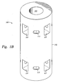
- Figure 1 B is a schematic view of one embodiment of a bushing shown in Figure 1A.
- Figure 1C is a schematic view of one embodiment of a bearing element shown in Figure 1A.
- Figure 1 D is a partial cross section view of the bearing elements shown in Figure 1C.
- Figure 2A is a schematic view of another embodiment of a support member described herein.
- Figure 2B is a top view of the support member shown in Figure 2A.
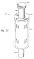
- Figure 2C is another schematic view of a fully assembled support member shown in Figure 2A.
- Figure 3 is a schematic sectional view of an exemplary plasma-enhanced chemical vapor deposition chamber utilizing the support members as shown in Figures 1A-D and Figures 2A-C, either alone or in combination.
- Figure 3A is a schematic sectional view of a particular embodiment of the plasma-enhanced chemical vapor deposition chamber shown in Figure 3.
- the chamber includes a lift-off plate to facilitate the transfer of a substrate on and off a susceptor.
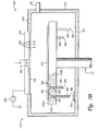
- Figure 3B is a schematic sectional view of another particular embodiment of the plasma-enhanced chemical vapor deposition chamber shown in Figure 3.
- the support members shown in Figures 1A-1C and 2A-2D are disposed at least partially within a support assembly disposed with the chamber.
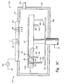
- Figure 3C is a schematic sectional view of yet another particular embodiment of the plasma-enhanced chemical vapor deposition chamber shown in Figure 3.
- the support members shown in Figures 1A-1C and 2A-2D are disposed at least partially within the support assembly as shown in Figure 3B.
- the chamber also includes a lift plate to activate the support members.
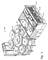
- Figure 4 is a schematic top-view of an exemplary multi-chamber processing system.
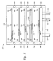
- Figure 5 is a cross section view of a batch-type heating or cooling cassette utilizing the support members, either alone or in combination, as shown in Figures 1 A-D and Figures 2A-C
- Figure 1A shows a schematic view of one embodiment of a support member 100.
- the support member 100 includes a bushing 102 having one or more bearing elements 110A, 110B (two are shown) and a support pin 120 at least partially disposed therein.
- a substrate such as any semiconductor substrate including a flat panel display, round wafer, liquid crystal display, glass panel substrate, plastic substrate, and the like, is supported thereon.
- the support member 100 is typically disposed on an upper surface of a support pedestal, susceptor, robot blade, shelf, or other member adapted to hold or support a substrate thereon (not shown).
- Figure 1 B shows a schematic view of the bushing 102.
- the bushing 102 is an annular member having a central bore 105 and one or more windows 107 formed therethrough.
- the bushing 102 resembles a cylindrical tube.
- the bushing 102 includes a first set of windows 107 located at a first end thereof and a second set of windows 107 located at a second end thereof.
- the actual number of windows 107 is a matter of design; however, it is preferable to have a set of four or more windows 107 located at the first end of the bushing 102 and a second set of four or more windows 107 located at the second end of the bushing 102. Additional sets of windows 107 may be desired based on the intended use and processing environment of the support member 100.
- FIG 1C shows a schematic view of the bearing elements 110A, 110B shown in Figure 1 A.
- Figure 1D shows a partial cross section view of the bearing elements 110A, 110B.
- the first bearing element 110A is housed within the first set of windows 107 at least partially formed through the first end of the bushing 102.
- the second bearing element 110B is housed within the second set of windows 107 at least partially formed through the second end of the bushing 102.
- each bearing element 110A, 110B includes one or more rollers 112 having a central bore 113 formed therethrough and a shaft 114 disposed at least partially through the central bore 113. The shaft 114 is secured to the bushing 102 to hold the roller 112 in place.
- each shaft 114 are chamfered to form a conical shape as shown in Figure 1 C.
- the rollers 112 are held into place via a friction fit facilitated by the ends of the shafts 114 arranged opposite one another. Cut outs 115 are helpful for manipulating the shafts 114 within the bushing 102.
- the bearing elements 110A, 110B support the pin 120 within the bushing 102.
- the bearing elements 110A, 110B also allow the support pin 120 to move axially through the bore 105 of the bushing 102 and rotate within the bore 105 with minimal resistance. Consequently, the bearing elements 110A, 110B reduce wear and tear on the support pin 120 and reduce unwanted particle generation caused by friction.
- each roller 112 preferably has an outer surface that is curved or concave to compliment the contour of the outer surface of the support pin 120, which is typically cylindrical in shape.
- the curved outer surface of the roller 112 provides a guide to facilitate movement of the pin 120 in an axial direction relative to the bushing 102.
- the curved outer surface of the roller 112 also allows the pin 120 to rotate freely within the bushing 102.
- the roller 112 may be constructed of any process compatible material, such as ceramics, graphite, stainless steel, aluminum, alloys thereof, and combinations thereof, for example.
- Figures 2A-C show a schematic view of another embodiment of a support member 200.
- the support member 200 includes a sleeve 210 and a bushing 202 having one or more bearing elements 220 at least partially disposed therein.
- the support member 200 also includes a flange 240 disposed about an upper end of the bushing 202.
- each of the one or more bearing elements 220 includes at least one spherical member 221.
- each of the one or more bearing elements 220 further includes four additional spherical members 222 having a smaller diameter than the spherical member 221.
- Each bearing element 220 is disposed within a ball seat or window 230 at least partially formed in the bushing 202.
- the sleeve 210 is disposed about the outer diameter of the bushing 202 to encapsulate the bearing elements 220 within their respective window 230.
- the flange 240 serves as a shoulder or stop for the sleeve 210.
- four windows 230 each having a bearing element 220 at least partially disposed therein are evenly spaced about a first diameter of the bushing 202 at a first end thereof and four windows 230 each having a bearing element 220 at least partially disposed therein are evenly spaced about a second diameter of the bushing 202 at a second end thereof.
- the cooperation of the windows 230 and the bearing elements 220 allow the support pin 120 to move axially within the bore 205 of the bushing 202 as well as to rotate about a central axis of the bushing 202.
- FIG. 2B shows a top view of the support member 200 shown in Figure 2A
- Figure 2C shows another schematic view of a fully assembled support member 200.
- the bushing 202 is an annular member having a central bore 205 formed therethrough.
- the bushing 202 resembles a cylindrical tube.
- the bearing elements 220A-D described above are each at least partially disposed within a respective window 230A-D at least partially formed in the bushing 202.
- the sleeve 210 is disposed about the outer diameter of the bushing 202, and the support pin 120 is at least partially disposed within the bore 205.
- the sleeve 210 and the support pin 120 collaborate to contain the balls 221, 222 within their respective window 230.
- the flange 240 may be a separate component as shown or the flange 240 may be an extended outer diameter of the bushing 202.
- the flange 240 prevents the sleeve 210 from traveling axially past the first end of the bushing 202.
- the support pin 120 is a cylindrical member having a first end 120A and a second end 120B as shown in Figures 1A and 2C.
- the support pin 120 may have a heavier lower portion or the second end 120B may be constructed of a heavier material to lower the overall center of gravity of the support pin 120.
- the lower portion of the pin 120 or the second end 120B may be constructed of a more dense material using materials, such as Teflon® or ceramic coated stainless steel, for example.
- the first end or pin head 120A directly contacts a substrate (not shown) to support the substrate.
- the first end 120A is coated with a material that reduces friction and is chemically inert with the substrate disposed thereon.
- the first end 120A may be coated with a chemically inert material to reduce or eliminate chemical reactions between the support pin 120 and the substrate supported thereon.
- the first end 120A may be coated with a material that minimizes friction with the substrate to reduce breakage or chipping.
- Exemplary coatings include but are not limited to ceramic materials and nitrides, such as silicon nitride, titanium nitride, and tantalum nitride, for example.
- the first end 120A has either a machined or polished finish or other suitable finish to produce a surface roughness of no more than 4 micro inches to minimize friction.
- a machined or polished finish or other suitable finish to produce a surface roughness of no more than 4 micro inches to minimize friction.
- the first end 120A may have a planar or substantially planar surface, as shown.
- the first end 120A may have a rounded upper portion that contacts a substrate disposed thereon.
- the rounded surface reduces surface area in contact with the substrate thereby reducing the chances of breaking or chipping the substrate disposed thereon.
- the rounded surface resembles a hemispherical, ellipsoidal, or parabolic shape.
- the first end 120A may be a two piece system having a cap (not shown) disposable on the body of the pin 120.
- the cap is preferably made of a ceramic material, and includes a hollow body to receive the body of the pin 120.
- the upper portion of the cap may be rounded and smoothed as discussed above.
- the cap may be coated as described above.
- U.S. Patent No. 6,528,767 which is incorporated by reference herein.
- the first end 120A may be a socket that retains a ball moveable within the socket.
- the ball makes contact with and supports the substrate disposed thereon.
- the ball is allowed to rotate and spin, much like a ball bearing, within the socket allowing the substrate to move across the ball without scratching.
- the ball is generally constructed of either metallic or non-metallic materials that provide friction reduction and/or inhibit chemical reaction between the ball and the substrate.
- the ball may include a metal or metal alloy, quartz, sapphire, silicon nitride or other suitable non-metallic materials.
- the ball has a surface finish of 4 micro-inches or smoother.
- the ball may further include the coating or coatings described above. A more detailed description of such a support pin may be found in U.S. Patent No. 6,528,767, which is incorporated by reference herein.
- the first end 120A may be a two piece system having a cap disposable on the body of the pin 120, whereby the cap includes the socket and ball configuration described above.
- a cap disposable on the body of the pin 120, whereby the cap includes the socket and ball configuration described above.
- a more detailed description of such a ball and socket may be found in co-pending U.S. Patent Application, serial no. 09/982,406, as well as serial no 10/376,857, both entitled “Substrate Support", and both assigned to Applied Materials, Inc. Both co-pending applications are incorporated by reference herein.
- the support members 100, 200 described herein are suitable for use in any testing chamber, processing chamber, or system that requires support of a substrate.
- the support members 100, 200 are particularly useful within a deposition chamber, such as a chemical vapor deposition (CVD) chamber or plasma enhanced chemical vapor deposition (PECVD) chamber.
- CVD chemical vapor deposition
- PECVD plasma enhanced chemical vapor deposition
- a PECVD chamber utilizing the support pins 100, 200 described herein is described below with reference to Figures 3 and 3A-3C.
- FIG. 3 shows a schematic sectional view of a plasma-enhanced chemical vapor deposition chamber 310.
- the PECVD chamber includes a chamber body 312 having an opening formed through a top wall 314 and a gas inlet manifold 316 disposed within the opening.
- the top wall 314 can be solid and the gas inlet manifold 316 is located adjacent an inner surface thereof.
- the gas inlet manifold 316 serves as an electrode and is connected to a power source 336, such as a RF power source.
- a susceptor or support member 318 is disposed within the chamber body 312.
- the susceptor 318 resembles the form of a plate and extends parallel to the gas inlet manifold 316.
- the susceptor 318 is typically made of aluminum and coated with a layer of aluminum oxide.
- the susceptor 318 is connected to ground and serves as a second electrode so as to connect the power source 336 across the gas inlet manifold 316 and the susceptor 318.
- the susceptor 318 is mounted on the end of a shaft 320 which extends vertically through a bottom wall 322 of the chamber body 312.
- the shaft 320 is movable so as to permit the movement of the susceptor 318 vertically up and down within the chamber body 312.
- Two or more support members 300 described above as support members 100 and 200, are disposed on an upper surface of the susceptor 318 to directly contact and support a substrate 325 therein. While there are only two support members 300 shown, any number of support members 300 may be arranged about the upper surface of the susceptor 318. The number and arrangement of the support members 300 depend on the shape and size of the substrate 325 to be processed as well as the process performed with the chamber 310.
- each support members 300 is identical, such as either the embodiment 100 described above or the embodiment 200 described above.
- the support members 300 may be a combination of the embodiments 100 and 200 described above.
- one or more of the support members 300 may be the embodiment 100 described above and one or more of the support members 300 may be the embodiment 200 described above.
- the chamber 310 further includes a gas outlet 330 extending through a side wall 332 of the chamber body 312.
- the gas outlet 330 is connected to a pump (not shown) for evacuating gases from the chamber body 312.
- a gas inlet conduit 342 is in fluid communication with the gas inlet manifold 316, and is connected through a gas switching network (not shown) to sources (not shown) of various gases. Process gases flow via the inlet conduit 342 through a showerhead 344, and into the chamber body 312.
- the showerhead 344 includes a plurality of apertures 340 formed therethrough to evenly distribute the gases across the surface of the substrate 325 to be processed below.
- Figure 3A shows a schematic sectional view of a particular embodiment of the plasma-enhanced chemical vapor deposition chamber 310 having a lift assembly 324 to facilitate the transfer of a substrate 325 on and off the susceptor 318.
- the lift assembly 324 extends horizontally between the susceptor 318 and the bottom wall 322 of the chamber body 312.
- the lift assembly 324 is substantially parallel to the susceptor 318 and is vertically movable.
- two or more support pins 300 are disposed on an upper surface of the lift assembly 324 instead of the upper surface of the susceptor 318.
- both the susceptor 318 and the lift assembly 324 may have two or more support pins 300 disposed on an upper surface thereof.
- the support pins 300 are positioned to extend through lift holes 328 formed through the susceptor 318. While there are only two support pins 300 shown, any number of support pins 100 (or 200) may be arranged about the upper surface of the lift assembly 324. The number and arrangement of the support pins 300 will depend on the size of the substrate 325 to be processed as well as the process performed with the chamber 310. As stated above, each support member 300 is identical, such as either the embodiment 100 or the embodiment 200 described herein, or alternatively, the support members 300 may be a combination of the embodiments 100 and 200.
- Figure 3B shows another embodiment of a PECVD chamber 310 having the support members 300 disposed at least partially within the support assembly 318.
- the support assembly 318 includes a plurality of holes 328 disposed therethrough.
- the support members 300 are disposed at least partially within these holes 328.
- a first end 302 of the support member 300 is substantially flush with or slightly recessed from an upper side 319A of the support assembly 318 when the support members 300 are in a normal position ( i . e ., retracted relative to the support assembly 318).
- a second end 304 of the support members 300 extends beyond a lower side 319B of the support assembly 318.
- the support members 300 come in contact with the bottom surface 322 of the chamber 312 and are displaced through the support assembly 318 to project from the upper side 319A of the support assembly 318, thereby placing the substrate 328 in a spaced-apart relation to the support assembly 318.
- the support members 300 may have varying lengths as shown so that the support members 300 contact with the bottom 322 and are actuated at different times. For example, longer support members 300 may be spaced around the outer edges of the substrate 325, and shorter support members 300 may be spaced inwardly from the outer edges toward the center of the substrate 325, allowing the substrate 325 to be gradually lifted from its outer edges to its center.
- the support members 300 may all be of uniform length, but the bottom 322 of the chamber 312 may include extensions or plateaus 351 positioned beneath selected support members 300 so that these selected support members 300 are actuated before the others.
- the chamber bottom 322 may comprise grooves or trenches (not shown) aligned beneath selected support members 300, so that these support members 300 are actuated after the others.
- Figure 3C shows yet another embodiment of a PECVD chamber 310 having the support members 300 disposed at least partially within the support assembly 318 as shown in Figure 3B, and also includes a lift plate 324 to activate the support members 300.
- the lift plate 324 is disposed proximate the underside 319B of the support assembly 318, and below the second ends 304 of the support members 300.
- the lift plate 324 is coupled to an actuator such as a pneumatic cylinder, hydraulic cylinder, lead screw, solenoid, stepper motor or other motion device (not shown) that is typically positioned outside of the chamber body 312.
- the vertical motions of the lift plate 324 and the support assembly 318 may be controlled via a single actuator utilizing a spring and a motion stop that controls the relative motion between the lift plate 324 and the support assembly 318.
- the lift plate 324 moves upward, contacting the second ends 304 of the support members 300, which extends the support members 300 beyond the upper surface of the support assembly 318.
- the support members 300 may each have different lengths to actuate the support members 300 at different times.
- the support members 300 disposed about the perimeter of the support assembly 318 are longer than the support members 300 disposed about the center of the support assembly 318.
- a reverse arrangement may also be useful.
- Testing chambers and processing chambers utilizing the support members 100, 200 described herein, such as the processing chamber 310 described above, may be integrated into a processing platform, such as an AKT 15K, 25K, or 40K PECVD System available from AKT, Inc., located in Santa Clara, California. Details of these PECVD Systems are described in commonly assigned U.S. Patent No. 5,512,320, entitled “Vacuum Processing Apparatus Having Improved Throughput", which is incorporated by reference herein.
- FIG. 4 shows a schematic top-view diagram of an exemplary multi-chamber processing system 400.
- the processing system 400 includes a central transfer chamber 412 to which are connected a load lock chamber 414 for transferring glass substrates into and out of the system 400.
- the processing system 400 also includes one or more processing chambers 438, 440, 442, 444, 446, 448 each disposed about the central transfer chamber 412. Any one or more of the processing chambers 438, 440, 442, 444, 446, 448 may be a chemical vapor deposition (CVD) chamber, a physical vapor deposition (PVD) chamber, an atomic layer deposition chamber (ALD), an annealing or heat treatment chamber, or any other processing chamber known in the art. Exemplary CVD chambers making use of the support members 100, 200, 300 described herein are shown and described above. The other processing chambers may have similar uses of the support members 100, 200, 300, and thus, will not be discussed in detail.
- CVD chemical vapor deposition
- the load lock chamber 414 includes a closable opening, such as a slit valve 416 disposed within a side wall thereof for transfer of the substrates into the vacuum environment of the processing system 400 from the atmosphere. Further, the load lock chamber 414 contains a cassette (not shown) fitted with a plurality of shelves or platforms for supporting and cooling multiple substrates therein, such as shown in Figure 5.
- a closable opening such as a slit valve 416 disposed within a side wall thereof for transfer of the substrates into the vacuum environment of the processing system 400 from the atmosphere.
- the load lock chamber 414 contains a cassette (not shown) fitted with a plurality of shelves or platforms for supporting and cooling multiple substrates therein, such as shown in Figure 5.
- Figure 5 shows a cross sectional view of a particular batch-type storage cassette 517.
- the cassette 517 includes side walls 512, 514, a bottom wall 516 and a lid 518.
- a plurality of channels 520 is disposed throughout the side walls 512, 514.
- the channels 520 may be in fluid communication with inlet and outlet conduits 524 and 526 for circulating a temperature controlled fluid therethough.
- the channels 520 may contain heating coils connected to a power source (not shown) via a conduit 527.
- the same conduits 524, 526 can be used for both enclosing the heating coils and for circulating the heat transfer medium in the channels 520.
- the interior of the side walls 512, 514 are fitted with a plurality of heat conductive shelves 560.
- the shelves 560 are in good thermal contact with the walls 512, 514 to insure rapid and uniform control of the temperature of the shelves 560.
- Examples of materials that may be used for the shelves 560 include, but are not limited to, aluminum, copper, stainless steel, clad copper, and the like.
- One or more supports 300 are suitably arranged on each shelf 560 to support a glass substrate 532 thereon.
- the supports 300 maintain the glass substrates 532 to be processed so that there is a gap between the shelves 560 and the glass substrates 532. This gap insures that direct contact between the shelf 560 and the glass substrate 532 is avoided which might stress and crack the glass substrates 532 or result in contaminants being transferred from the shelf 560 to the glass substrate 532.
- the glass substrates 532 are heated indirectly by radiation and gas conduction rather than by direct contact of the glass substrate 532 and the shelves 560. Further, the interleaving of the glass substrates 532 and the shelves 560 provides heating to transfer the glass substrates 532 from both above and below, providing more rapid and more uniform heating of the glass substrates 532.
- the glass substrates can be loaded into the processing system 400 manually or in an automated fashion.
- a commercially available robot 474 mounted on a rail frame 480 outside the processing system 400 at a first station opposite the load lock chamber 414 can retrieve a glass substrate from a storage cassette 417A, B or C, and load the glass substrates one at a time into the processing system 400 via the load lock chamber 414.
- the robot 474 can retrieve processed substrates from the load lock chamber 414 and return the substrates to one of the storage cassettes 417A, B or C.
- a robot (not shown in this view) disposed within the transfer chamber 412 moves and positions the glass substrates within the processing system 400.
Landscapes
- Chemical & Material Sciences (AREA)
- Engineering & Computer Science (AREA)
- General Engineering & Computer Science (AREA)
- Mechanical Engineering (AREA)
- Organic Chemistry (AREA)
- Chemical Kinetics & Catalysis (AREA)
- General Chemical & Material Sciences (AREA)
- Materials Engineering (AREA)
- Geochemistry & Mineralogy (AREA)
- Life Sciences & Earth Sciences (AREA)
- Metallurgy (AREA)
- Container, Conveyance, Adherence, Positioning, Of Wafer (AREA)
- Chemical Vapour Deposition (AREA)
Abstract
Description
Embodiments of the present invention generally relate to a substrate support pin. More particularly, embodiments of the present invention relate to a support pin for large glass panels. Specifically, the present invention relates to a support member, a process chamber and a method of processing.
The present invention intends to overcome at least some of the above problems. The object is solved by the substrate support member according to independent claims 1, 6, 9, and 52, by the process chamber according to independent claims 21, and 33; and the method for processing a substrate according to independent claim 40.
Further advantages, features, aspects and details of the invention are evident from the dependent claims, the description and the drawings.
The invention is also directed to apparatuses for carrying out the disclosed methods and including apparatus parts for performing each described method steps. These method steps may be performed by way of hardware components, a computer programmed by appropriate software, by any combination of the two or in any other manner. Furthermore, the invention is also directed to methods by which the described apparatus operates. It includes method steps for carrying out every function of the apparatus or manufacturing every part of the apparatus.
Claims (56)
- A substrate support member (100; 200; 300), comprising:a housing having a bore (105; 205) formed therethrough; anda plurality of bearing elements (110; 220) disposed within the bore comprising a central bored formed therethrough, a contoured outer surface, and a shaft at least partially disposed through the central bore.
- The support member of claim 1, wherein the housing comprises four windows formed therethrough at a first end thereof and four windows (107; 230) formed therethrough at a second end thereof, each window having one of the bearing elements at least partially disposed therein.
- The support member of any of the preceding claims, wherein the bearing elements include a concave outer surface to compliment an outer diameter of a support pin disposed within the bore of the housing.
- The support member of any of the preceding claims, wherein each bearing element is a roller (112).
- The support member of any of the preceding claims, wherein each bearing element is a roller in physical contact with a support pin disposed within the bore of the housing.
- A substrate support member (100; 200; 300), comprising:a housing having a bore (105; 205) formed therethrough;a support pin at least partially disposed within the bore; anda plurality of rollers (112) disposed about the housing, wherein each roller comprises a central bore formed therethrough, a contoured outer surface, and a shaft at least partially disposed through the central bore.
- The support member of claim 6, wherein the housing comprises four windows (107; 230) formed therethrough at a first end thereof and four windows formed therethrough at a second end thereof, each window having one of the bearing elements at least partially disposed therein.
- The support member of any of claims 6 to 7, wherein the support pin has a circular cross section and each roller has a concave outer surface to compliment an outer diameter of the support pin.
- A substrate support member (100; 200), comprising:a housing having a bore formed therethrough;a support pin at least partially disposed within the bore (105; 205); anda plurality of bearing elements (110; 220) disposed about the housing.
- The support member of claim 9, wherein the housing comprises at least four windows (107; 230) formed therethrough, each window having one of the bearing elements at least partially disposed therein.
- The support member of any of claims 9 to 10, wherein the housing comprises four windows formed therethrough at a first end thereof and four windows formed therethrough at a second end thereof, each window having one of the bearing elements at least partially disposed therein.
- The support member of any of claims 9 to 11, wherein at least one of the bearing elements comprises a roller (112) having a central bore formed therethrough, a contoured outer surface, and a shaft at least partially disposed through the central bore.
- The support member of claim 12, wherein the support pin has a circular cross section and each roller has a concave outer surface to compliment an outer diameter of the support pin.
- The support member of any of claims 9 to 13, wherein the housing comprises four windows formed therethrough at a first end thereof and four windows formed therethrough at a second end thereof, each window having one of the bearing elements at least partially disposed therein, the bearing elements comprising a roller (112) having a central bore formed therethrough, a contoured outer surface, and a shaft at least partially disposed through the central bore.
- The support member of claim 9, wherein at least one of the bearing elements (220) comprises a ball assembly comprising a larger spherical member (221) and four smaller spherical members (222) arranged about the larger spherical member.
- The support member of any of claims 9 or 15, wherein the larger spherical member and the four smaller spherical members are disposed within a ball seat formed in the housing.
- The support member of any of claims 9 or 15 to 16, further comprising a hollow sleeve (210) disposed about the housing.
- The support member of claim 17, wherein the hollow sleeve is adapted to secure the bearing elements to the housing.
- The support member of claim 18, further comprising a socket disposed about a first end of the housing, the socket being adapted to abut a first end of the hollow sleeve.
- The support member of claim 9, wherein the housing comprises four ball seats formed therethrough at a first end thereof, and four ball seats formed therethrough at a second end thereof, each ball seat having one of the bearing elements at least partially disposed therein, the bearing elements comprising a ball assembly comprising a larger spherical member (221) and four smaller spherical members (222) arranged about the larger spherical member.
- A processing chamber, comprising:A chamber body having a support pedestal disposed therein;two or more support members each disposed on an upper surface of the support pedestal, the support members (100; 200; 300) comprising:a housing having a bore formed therethrough;a support pin at least partially disposed within the bore; anda plurality of bearing elements disposed within the bore.
- The processing chamber of claim 21, wherein the housing comprises at least four windows (107; 230) formed therethrough, each window having one of the bearing elements at least partially disposed therein.
- The processing chamber of any of claims 21 to 22, wherein the housing comprises four windows formed therethrough at a first end thereof and four windows formed therethrough at a second end thereof, each window having one of the bearing elements at least partially disposed therein.
- The processing chamber of claim 21 to 23, wherein at least one of the bearing elements comprises a roller having a central bore formed therethrough, a contoured outer surface, and a shaft at least partially disposed through the central bore.
- The processing chamber of claim 24, wherein the support pin has a circular cross section and each roller (112) has a concave outer surface to compliment an outer diameter of the support pin.
- The processing chamber of any of claims 21 to 25, wherein the housing comprises four windows formed therethrough at a first end thereof and four windows formed therethrough at a second end thereof, each window having one of the bearing elements at least partially disposed therein, the bearing elements comprising a roller having a central bore formed therethrough, a contoured outer surface and a shaft at least partially disposed through the central bore.
- The processing chamber of claim 21, wherein at least one of the bearing elements comprises a ball assembly comprising a larger spherical member and four smaller spherical members arranged about the larger spherical member.
- The processing chamber of claim 27, wherein the larger spherical member (221) and the four smaller spherical members (222) are disposed within a ball seat formed in the housing.
- The processing chamber of claim 21, further comprising a hollow sleeve (210) disposed about the housing.
- The processing chamber of claim 29, wherein the hollow sleeve is adapted to secure the bearing elements to the housing.
- The processing chamber of claim 30, further comprising a socket disposed about a first end of the housing, the socket being adapted to abut a first end of the hollow sleeve.
- The processing chamber of claim 21, wherein the housing comprises four ball seats formed therethrough at a first end thereof, and four ball seats formed therethrough at a second end thereof, each ball seat having one of the bearing elements at least partially disposed therein, the bearing elements comprising a ball assembly comprising a larger spherical member and four smaller spherical members arranged about the larger spherical member.
- A processing chamber, comprising:a chamber body having a support pedestal disposed therein;a lift assembly disposed within the chamber body, adjacent the support pedestal, the lift assembly being adapted to load and unload substrates to and from the support pedestal;two or more support members (100; 200) each disposed on an upper surface of the lift assembly, the support members comprising:a housing having a bore formed therethrough;a support pin at least partially disposed within the bore; anda plurality of bearing elements (110; 220) disposed within the bore.
- The processing chamber of claim 33, wherein at least one of the bearing elements comprises a ball assembly comprising a larger spherical member and four smaller spherical members arranged about the larger spherical member.
- The processing chamber of claim 34, wherein the larger spherical member (221) and the four smaller spherical members (222) are disposed within a seat formed in the housing.
- The processing chamber of any of claims 33 to 35, further comprising a hollow sleeve (210) disposed about the housing.
- The processing chamber of claim 36, wherein the hollow sleeve is adapted to secure the bearing elements to the housing.
- The processing chamber of any of claims 33 to 37, further comprising a socket disposed about a first end of the housing, the socket being adapted to abut a first end of the hollow sleeve.
- The processing chamber of any of claims 33 to 38, wherein the housing comprises four ball seats formed therethrough at a first end thereof, and four ball seats formed therethrough at a second end thereof, each ball seat having one of the bearing elements at least partially disposed therein, the bearing elements comprising a ball assembly comprising a larger spherical member and four smaller spherical members arranged about the larger spherical member.
- A method for processing a substrate, comprising:loading a substrate to be processed within a processing system, the system having at least one support pedestal disposed therein; andarranging the substrate on an upper surface of the support pedestal, the support pedestal having two or more support members (100; 200; 300) disposed thereon, the support members comprising:a housing having a bore formed therethrough;a support pin (120) at least partially disposed within the bore; anda plurality of bearing elements (110; 220) disposed within the bore.
- The method of claim 40, wherein the housing comprises at least four windows formed therethrough, each window having one of the bearing elements at least partially disposed therein.
- The method of any of claims 40 to 41, wherein the housing comprises four windows (107; 230) formed therethrough at a first end thereof and four windows formed therethrough at a second end thereof, each window having one of the bearing elements at least partially disposed therein.
- The method of any of claims 40 to 42, wherein at least one of the bearing elements comprises a roller having a central bore formed therethrough, a contoured outer surface, and a shaft at least partially disposed through the central bore.
- The method of claim 43, wherein the support pin has a circular cross section and each roller (112) has a concave outer surface to compliment an outer diameter of the support pin.
- The method of any of claims 40 to 44, wherein the housing comprises four windows formed therethrough at a first end thereof and four windows formed therethrough at a second end thereof, each window having one of the bearing elements at least partially disposed therein, the bearing elements comprising a roller having a central bore formed therethrough, a contoured outer surface, and a shaft at least partially disposed through the central bore.
- The method of claim 40, wherein at least one of the bearing elements comprises a ball assembly comprising a larger spherical member (221) and four smaller spherical members (222) arranged about the larger spherical member.
- The method of claim 46, wherein the larger spherical member and the four smaller spherical members are disposed within a ball seat formed in the housing.
- The method of any of claims 40 or 46, further comprising a hollow sleeve (210) disposed about the housing.
- The method of claim 48, wherein the hollow sleeve is adapted to secure the bearing elements to the housing.
- The method of claim 48, further comprising a socket disposed about a first end of the housing, the socket being adapted to abut a first end of the hollow sleeve.
- The method of any of claims 40 or 46 to 50, wherein the housing comprises four ball seats formed therethrough at a first end thereof, and four ball seats formed therethrough at a second end thereof, each ball seat having one of the bearing elements at least partially disposed therein, the bearing elements comprising a ball assembly comprising a larger spherical member and four smaller spherical members arranged about the larger spherical member.
- A substrate support member (100; 200; 300), comprising:a housing having a bore formed therethrough; anda plurality of bearing elements disposed within the bore wherein at least one of the bearing elements comprises a ball assembly comprising a larger spherical member (221) and four smaller spherical members (222) arranged about the larger spherical member.
- The support member of claim 52, wherein the larger spherical member and the four smaller spherical members are disposed within a seat formed in the housing.
- The support member of any of claims 52 to 53, further comprising a hollow sleeve disposed about the housing.
- The support member of any of claims 52 to 54, further comprising a support pin at least partially disposed within the bore.
- The support member of any of claims 52 to 55, wherein the housing comprises four ball seats formed therethrough at a first end thereof, and four ball seats formed therethrough at a second end thereof, each ball seat having one of the bearing elements at least partially disposed therein.
Applications Claiming Priority (2)
| Application Number | Priority Date | Filing Date | Title |
|---|---|---|---|
| US779130 | 2004-02-12 | ||
| US10/779,130 US8033245B2 (en) | 2004-02-12 | 2004-02-12 | Substrate support bushing |
Publications (2)
| Publication Number | Publication Date |
|---|---|
| EP1564791A2 true EP1564791A2 (en) | 2005-08-17 |
| EP1564791A3 EP1564791A3 (en) | 2006-08-09 |
Family
ID=34701410
Family Applications (1)
| Application Number | Title | Priority Date | Filing Date |
|---|---|---|---|
| EP04026466A Withdrawn EP1564791A3 (en) | 2004-02-12 | 2004-11-08 | Substrate support bushing |
Country Status (6)
| Country | Link |
|---|---|
| US (2) | US8033245B2 (en) |
| EP (1) | EP1564791A3 (en) |
| JP (1) | JP4473144B2 (en) |
| KR (3) | KR100597495B1 (en) |
| CN (2) | CN1655336B (en) |
| TW (1) | TWI260064B (en) |
Cited By (2)
| Publication number | Priority date | Publication date | Assignee | Title |
|---|---|---|---|---|
| US8216422B2 (en) * | 2004-02-12 | 2012-07-10 | Applied Materials, Inc. | Substrate support bushing |
| EP4105503A1 (en) * | 2021-06-18 | 2022-12-21 | Goodrich Actuation Systems SAS | Linear motor system guide |
Families Citing this family (46)
| Publication number | Priority date | Publication date | Assignee | Title |
|---|---|---|---|---|
| US20060016398A1 (en) * | 2004-05-28 | 2006-01-26 | Laurent Dubost | Supporting and lifting device for substrates in vacuum |
| KR101144587B1 (en) * | 2004-11-09 | 2012-05-14 | 주성엔지니어링(주) | Lift-pin holder |
| JP4906375B2 (en) * | 2006-03-20 | 2012-03-28 | 東京応化工業株式会社 | Substrate support member |
| US7997227B2 (en) * | 2007-03-13 | 2011-08-16 | General Electric Company | Vacuum coater device and mechanism for supporting and manipulating workpieces in same |
| KR101433864B1 (en) * | 2007-11-30 | 2014-09-01 | 주성엔지니어링(주) | Substrate elevating device |
| USD640715S1 (en) * | 2008-11-17 | 2011-06-28 | Applied Materials, Inc. | Lift pin assembly |
| USD635597S1 (en) | 2008-11-17 | 2011-04-05 | Applied Materials, Inc. | Lift pin |
| US20100151127A1 (en) * | 2008-12-12 | 2010-06-17 | Applied Materials, Inc. | Apparatus and method for preventing process system contamination |
| KR101045247B1 (en) | 2008-12-12 | 2011-06-29 | 엘아이지에이디피 주식회사 | Lift pin lifting device |
| USD650818S1 (en) * | 2008-12-19 | 2011-12-20 | Applied Materials, Inc. | Inner lift pin |
| US20110014396A1 (en) * | 2009-07-14 | 2011-01-20 | Applied Materials, Inc. | Recirculating linear rolling bushing |
| WO2011009007A2 (en) * | 2009-07-15 | 2011-01-20 | Applied Materials, Inc. | Improved lift pin guides |
| DE102009035950B4 (en) * | 2009-08-03 | 2011-09-01 | Siemens Aktiengesellschaft | Guide element for creasing hose |
| WO2011017226A2 (en) * | 2009-08-07 | 2011-02-10 | Applied Materials, Inc. | Compound lift pin tip with temperature compensated attachment feature |
| KR101628918B1 (en) * | 2009-12-22 | 2016-06-09 | 주성엔지니어링(주) | Apparatus for treatmenting substrate |
| JP2012162752A (en) * | 2011-02-03 | 2012-08-30 | Taiyo Nippon Sanso Corp | Vapor phase growing apparatus |
| KR101296966B1 (en) * | 2011-05-25 | 2013-08-14 | 에스케이씨솔믹스 주식회사 | Roller Bushing |
| CN103132051B (en) * | 2011-11-23 | 2015-07-08 | 中微半导体设备(上海)有限公司 | Chemical vapor deposition reactor or epitaxial layer growth reactor and its supporting device |
| TW201330170A (en) * | 2011-11-28 | 2013-07-16 | 特艾希米控公司 | Support pin for supporting substrate and substrate processing apparatus using the same |
| CN103247711B (en) * | 2012-02-14 | 2016-03-30 | 理想能源设备(上海)有限公司 | A kind of push rod component for lifting substrate |
| US9590468B2 (en) * | 2012-10-08 | 2017-03-07 | Exro Technologies Inc. | Electrical machines such as generators and motors |
| US10857655B2 (en) * | 2013-03-13 | 2020-12-08 | Applied Materials, Inc. | Substrate support plate with improved lift pin sealing |
| US9991153B2 (en) * | 2013-03-14 | 2018-06-05 | Applied Materials, Inc. | Substrate support bushing |
| US9316261B2 (en) * | 2014-02-10 | 2016-04-19 | NADELLA S.r.l. | Linear guide system |
| KR102239477B1 (en) * | 2014-04-30 | 2021-04-13 | 주성엔지니어링(주) | Lift pin assembly |
| KR200480806Y1 (en) * | 2015-07-10 | 2016-07-08 | 김길중 | Susceptor for chemical of vapor deposition apparatus |
| KR102511875B1 (en) * | 2016-05-09 | 2023-03-17 | 주성엔지니어링(주) | Support unit for lift fins and substrate processing apparatus using the same |
| KR102723647B1 (en) * | 2016-10-12 | 2024-10-29 | 램 리써치 코포레이션 | Pad raising mechanism in wafer positioning pedestal for semiconductor processing |
| US10262887B2 (en) * | 2016-10-20 | 2019-04-16 | Lam Research Corporation | Pin lifter assembly with small gap |
| KR20180075021A (en) * | 2016-12-26 | 2018-07-04 | 에스케이실트론 주식회사 | A rotary shaft of the wafer stage |
| CN106601659B (en) * | 2016-12-30 | 2024-02-02 | 上海新阳半导体材料股份有限公司 | New wafer transfer device |
| US11004722B2 (en) | 2017-07-20 | 2021-05-11 | Applied Materials, Inc. | Lift pin assembly |
| KR102427077B1 (en) * | 2017-09-04 | 2022-07-29 | 주성엔지니어링(주) | Supporting structure |
| DE102017122754A1 (en) * | 2017-09-29 | 2019-04-04 | MAX-PLANCK-Gesellschaft zur Förderung der Wissenschaften e.V. | Device and vacuum chamber |
| CN108330468B (en) * | 2018-03-14 | 2023-06-30 | 深圳市志橙半导体材料有限公司 | Matrix supporting device and matrix rotation driving device of chemical vapor deposition furnace |
| CN110835739A (en) * | 2018-08-17 | 2020-02-25 | 中智(泰兴)电力科技有限公司 | 7-cavity vertical PECVD-PVD integrated silicon wafer coating process |
| US10763154B2 (en) * | 2018-08-28 | 2020-09-01 | Applied Materials, Inc. | Measurement of flatness of a susceptor of a display CVD chamber |
| CN109487240A (en) * | 2018-12-11 | 2019-03-19 | 武汉华星光电半导体显示技术有限公司 | For the roller bush sub-assembly in chemical vapor deposition chamber |
| KR102772197B1 (en) * | 2019-11-04 | 2025-02-26 | 삼성디스플레이 주식회사 | Deposition apparatus and method of processing substrate using the same |
| KR20250164864A (en) * | 2019-11-22 | 2025-11-25 | 램 리써치 코포레이션 | Coin-slot and ball-lock ceramic lift pin holders |
| KR20220091614A (en) * | 2019-11-26 | 2022-06-30 | 램 리써치 코포레이션 | Carrier ring to pedestal kinematic mount for substrate processing tool |
| WO2021168025A1 (en) * | 2020-02-20 | 2021-08-26 | Lam Research Corporation | Wafer lift pin mechanism for preventing local backside deposition |
| US11261910B1 (en) * | 2020-11-10 | 2022-03-01 | Raytheon Company | Multi-layer linear bearing |
| CN113652673B (en) * | 2021-09-15 | 2023-11-24 | 福建华佳彩有限公司 | Chemical vapor deposition platen structure and control method thereof |
| KR102524499B1 (en) * | 2022-12-27 | 2023-04-21 | 주식회사 디타스 | Spooler assembly sticking prevention system of submarine winch system |
| US20240332058A1 (en) * | 2023-03-28 | 2024-10-03 | Applied Materials, Inc. | Substrate support assembly |
Family Cites Families (108)
| Publication number | Priority date | Publication date | Assignee | Title |
|---|---|---|---|---|
| US607576A (en) * | 1898-07-19 | Journal-bearing | ||
| GB558935A (en) | 1942-11-05 | 1944-01-27 | Blackburn Aircraft Ltd | Improvements in and relating to bearing supports for axially movable rods |
| US2889180A (en) * | 1954-11-22 | 1959-06-02 | Earl R Jorgensen | Roller bearing construction |
| CH327414A (en) | 1955-06-08 | 1958-01-31 | Amagasaki Seitetsu Kabushiki K | Antifriction support device for moving body |
| US2907610A (en) * | 1956-02-01 | 1959-10-06 | Anderson Co | Bearing structure |
| US2983553A (en) * | 1959-02-24 | 1961-05-09 | Wilbur H Dexter | Linear bearing |
| US3269128A (en) * | 1963-11-15 | 1966-08-30 | Rusche Fredric | Coupled pile driving mandrel |
| US3347603A (en) * | 1965-04-12 | 1967-10-17 | Ignatjev Vladimir | Axial bearing |
| US3469893A (en) * | 1967-03-13 | 1969-09-30 | Arthur F Hudson | Bearing construction |
| US3589202A (en) * | 1969-03-19 | 1971-06-29 | Richard B Stanley | Linear actuator |
| US3582161A (en) * | 1969-07-07 | 1971-06-01 | Arthur F Hudson | Bearing construction |
| US3622211A (en) * | 1969-11-10 | 1971-11-23 | Robert E Mitton | Linear roller bearing unit |
| US3887247A (en) * | 1974-02-25 | 1975-06-03 | Us Energy | Bearing mounting for telescoping tubes |
| US4265320A (en) * | 1977-05-16 | 1981-05-05 | Matsushita Electric Industrial Co., Ltd. | Electrically powered torque-controlled tool |
| US4334436A (en) * | 1980-08-21 | 1982-06-15 | F. Jos. Lamb Company | Bearing arrangement for oscillating shafts |
| US4346945A (en) * | 1980-09-26 | 1982-08-31 | Nobuyuki Tsuboi | Multipurpose reciprocal bearing unit |
| US4382739A (en) * | 1980-12-24 | 1983-05-10 | International Business Machines Corporation | Light actuating force elevator drive mechanism |
| CH659690A5 (en) * | 1983-03-29 | 1987-02-13 | Fernand Moser | LINEAR OR ROTATIONAL GUIDANCE. |
| US4621936A (en) | 1983-10-14 | 1986-11-11 | Corning Glass Works | Zirconia pen balls |
| FR2591138B1 (en) | 1985-12-10 | 1988-04-08 | Recif Sa | PROCESS FOR MANUFACTURING MOUTHPIECES FOR VACUUM PIPETTES IN PARTICULAR AND THE MOUTHPIECES OBTAINED BY IMPLEMENTING THE PROCESS. |
| US4635452A (en) * | 1986-01-21 | 1987-01-13 | Olson Manufacturing Company | Double-acting barrel lock and key |
| DE3623970A1 (en) * | 1986-07-16 | 1988-01-28 | Leybold Heraeus Gmbh & Co Kg | TRANSPORTATION DEVICE WITH ROLLER SYSTEMS FOR VACUUM COATING SYSTEMS |
| JPH0719150Y2 (en) | 1986-10-31 | 1995-05-01 | 日本真空技術株式会社 | Wafer transfer hand |
| US4842683A (en) * | 1986-12-19 | 1989-06-27 | Applied Materials, Inc. | Magnetic field-enhanced plasma etch reactor |
| WO1989003276A1 (en) | 1987-10-13 | 1989-04-20 | Extrude Hone Corp | Method and apparatus for aligning two components |
| KR0155545B1 (en) | 1988-06-27 | 1998-12-01 | 고다까 토시오 | Heat treatment apparatus of the board |
| US5238499A (en) * | 1990-07-16 | 1993-08-24 | Novellus Systems, Inc. | Gas-based substrate protection during processing |
| US5160238A (en) * | 1990-07-18 | 1992-11-03 | Hermco | Shaft travel devices such as vertical lift arm devices |
| US5236264A (en) * | 1991-06-10 | 1993-08-17 | Nsk Ltd. | Linear bearing |
| US5445486A (en) | 1992-03-29 | 1995-08-29 | Tokyo Electron Sagami Limited | Substrate transferring apparatus |
| US5356476A (en) * | 1992-06-15 | 1994-10-18 | Materials Research Corporation | Semiconductor wafer processing method and apparatus with heat and gas flow control |
| US5370739A (en) * | 1992-06-15 | 1994-12-06 | Materials Research Corporation | Rotating susceptor semiconductor wafer processing cluster tool module useful for tungsten CVD |
| US5607009A (en) | 1993-01-28 | 1997-03-04 | Applied Materials, Inc. | Method of heating and cooling large area substrates and apparatus therefor |
| JP3045431B2 (en) | 1993-02-19 | 2000-05-29 | 東京エレクトロン株式会社 | Slide bearing |
| JPH06280864A (en) * | 1993-03-29 | 1994-10-07 | Ntn Corp | Needle roller bearing |
| GB2277560A (en) | 1993-04-30 | 1994-11-02 | Itp Limited | Adjustable bearing and machine slide |
| US5437440A (en) * | 1993-08-20 | 1995-08-01 | Compact Air Products, Inc. | Swing apparatus |
| JP3172758B2 (en) * | 1993-11-20 | 2001-06-04 | 東京エレクトロン株式会社 | Plasma etching method |
| DE4416319A1 (en) * | 1994-05-09 | 1995-11-16 | Schaeffler Waelzlager Kg | Bearing unit with a centering and a flange |
| JP3151118B2 (en) | 1995-03-01 | 2001-04-03 | 東京エレクトロン株式会社 | Heat treatment equipment |
| US6193506B1 (en) * | 1995-05-24 | 2001-02-27 | Brooks Automation, Inc. | Apparatus and method for batch thermal conditioning of substrates |
| US5830277A (en) * | 1995-05-26 | 1998-11-03 | Mattson Technology, Inc. | Thermal processing system with supplemental resistive heater and shielded optical pyrometry |
| JP2739452B2 (en) * | 1995-06-28 | 1998-04-15 | 重雄 高橋 | Assembled linear bearing and method of assembling the same |
| US5788458A (en) | 1995-07-10 | 1998-08-04 | Asyst Technologies, Inc. | Method and apparatus for vertical transfer of a semiconductor wafer cassette |
| US6113702A (en) * | 1995-09-01 | 2000-09-05 | Asm America, Inc. | Wafer support system |
| US5605574A (en) | 1995-09-20 | 1997-02-25 | Kabushiki Kaisha Toshiba | Semiconductor wafer support apparatus and method |
| JP3328763B2 (en) | 1995-10-30 | 2002-09-30 | エヌティティエレクトロニクス株式会社 | Wafer support structure for vertical wafer boat |
| JP3005461B2 (en) | 1995-11-24 | 2000-01-31 | 日本電気株式会社 | Electrostatic chuck |
| US5850071A (en) | 1996-02-16 | 1998-12-15 | Kokusai Electric Co., Ltd. | Substrate heating equipment for use in a semiconductor fabricating apparatus |
| US5893647A (en) * | 1996-03-15 | 1999-04-13 | Isel Co., Ltd. | Bearing retainer for a sliding mechanism for use in a machine tool |
| JP3163973B2 (en) * | 1996-03-26 | 2001-05-08 | 日本電気株式会社 | Semiconductor wafer chuck device and semiconductor wafer peeling method |
| US5796066A (en) * | 1996-03-29 | 1998-08-18 | Lam Research Corporation | Cable actuated drive assembly for vacuum chamber |
| US5788304A (en) | 1996-05-17 | 1998-08-04 | Micron Technology, Inc. | Wafer carrier having both a rigid structure and resistance to corrosive environments |
| US6091498A (en) * | 1996-07-15 | 2000-07-18 | Semitool, Inc. | Semiconductor processing apparatus having lift and tilt mechanism |
| US6120609A (en) * | 1996-10-25 | 2000-09-19 | Applied Materials, Inc. | Self-aligning lift mechanism |
| US5836575A (en) | 1996-10-30 | 1998-11-17 | Micron Electronics, Inc. | Wafer manual handpick station |
| US5844195A (en) * | 1996-11-18 | 1998-12-01 | Applied Materials, Inc. | Remote plasma source |
| US5984391A (en) * | 1997-02-03 | 1999-11-16 | Novellus Systems, Inc. | Microfeature wafer handling apparatus and methods |
| KR100284567B1 (en) * | 1997-04-15 | 2001-04-02 | 후지이 아키히로 | Vertical wafer boat |
| US6118100A (en) * | 1997-11-26 | 2000-09-12 | Mattson Technology, Inc. | Susceptor hold-down mechanism |
| US6257827B1 (en) * | 1997-12-01 | 2001-07-10 | Brooks Automation Inc. | Apparatus and method for transporting substrates |
| JP3456890B2 (en) | 1998-01-16 | 2003-10-14 | 東京エレクトロン株式会社 | Substrate processing equipment |
| US6250619B1 (en) * | 1998-02-03 | 2001-06-26 | Cna Manufacturing Systems, Inc. | Clamp suitable for use at high temperatures in a flexible tooling apparatus |
| US6077026A (en) * | 1998-03-30 | 2000-06-20 | Progressive System Technologies, Inc. | Programmable substrate support for a substrate positioning system |
| US6596086B1 (en) * | 1998-04-28 | 2003-07-22 | Shin-Etsu Handotai Co., Ltd. | Apparatus for thin film growth |
| US6085670A (en) * | 1998-05-05 | 2000-07-11 | Genmark Automation, Inc. | Tiltable Z-axis platform based on uni-directional tilt platform |
| US6213704B1 (en) * | 1998-05-20 | 2001-04-10 | Applied Komatsu Technology, Inc. | Method and apparatus for substrate transfer and processing |
| US6146504A (en) * | 1998-05-21 | 2000-11-14 | Applied Materials, Inc. | Substrate support and lift apparatus and method |
| JPH11351250A (en) | 1998-06-12 | 1999-12-24 | Sony Corp | Bearing device |
| US6170433B1 (en) * | 1998-07-23 | 2001-01-09 | Applied Materials, Inc. | Method and apparatus for processing a wafer |
| US20010001384A1 (en) * | 1998-07-29 | 2001-05-24 | Takeshi Arai | Silicon epitaxial wafer and production method therefor |
| JP2000091406A (en) | 1998-09-08 | 2000-03-31 | Mitsubishi Materials Silicon Corp | Wafer holder |
| US6143147A (en) * | 1998-10-30 | 2000-11-07 | Tokyo Electron Limited | Wafer holding assembly and wafer processing apparatus having said assembly |
| JP2000150402A (en) | 1998-11-09 | 2000-05-30 | Shin Etsu Handotai Co Ltd | Substrate supporting jig |
| JP2000145914A (en) * | 1998-11-17 | 2000-05-26 | Tsubakimoto Chain Co | Bearing linear actuator with backstop mechanism |
| US6256555B1 (en) * | 1998-12-02 | 2001-07-03 | Newport Corporation | Robot arm with specimen edge gripping end effector |
| KR100309920B1 (en) * | 1998-12-16 | 2002-10-25 | 삼성전자 주식회사 | An unloading apparatus of a substrate and unloading method thereof |
| JP3579278B2 (en) * | 1999-01-26 | 2004-10-20 | 東京エレクトロン株式会社 | Vertical heat treatment device and sealing device |
| US6378816B1 (en) * | 1999-06-04 | 2002-04-30 | Joel W. Pfister | Linear motion table leg |
| US6187134B1 (en) * | 1999-07-09 | 2001-02-13 | The Board Of Trustees Of The Leland Stanford Junior University | Reusable wafer support for semiconductor processing |
| US6322116B1 (en) * | 1999-07-23 | 2001-11-27 | Asm America, Inc. | Non-contact end effector |
| US6452195B1 (en) * | 1999-08-18 | 2002-09-17 | Ibis Technology Corporation | Wafer holding pin |
| US6345150B1 (en) * | 1999-11-30 | 2002-02-05 | Wafermasters, Inc. | Single wafer annealing oven |
| US6572708B2 (en) * | 2000-02-28 | 2003-06-03 | Applied Materials Inc. | Semiconductor wafer support lift-pin assembly |
| JP2001317550A (en) * | 2000-05-08 | 2001-11-16 | Hiihaisuto Seiko Kk | Linear bearing |
| JP2002213444A (en) | 2001-01-22 | 2002-07-31 | Isel Co Ltd | Guide device |
| US20020124706A1 (en) | 2000-12-05 | 2002-09-12 | Isel Co., Ltd. | Guide device for linear motion |
| JP2002174234A (en) | 2000-12-05 | 2002-06-21 | Isel Co Ltd | Linear guide |
| JP4484376B2 (en) * | 2001-01-22 | 2010-06-16 | アイセル株式会社 | Guide device |
| US6935466B2 (en) * | 2001-03-01 | 2005-08-30 | Applied Materials, Inc. | Lift pin alignment and operation methods and apparatus |
| US6709721B2 (en) * | 2001-03-28 | 2004-03-23 | Applied Materials Inc. | Purge heater design and process development for the improvement of low k film properties |
| KR100798179B1 (en) * | 2001-04-27 | 2008-01-24 | 교세라 가부시키가이샤 | Wafer heater |
| US6528767B2 (en) * | 2001-05-22 | 2003-03-04 | Applied Materials, Inc. | Pre-heating and load lock pedestal material for high temperature CVD liquid crystal and flat panel display applications |
| JP4205897B2 (en) | 2001-07-09 | 2009-01-07 | アイセル株式会社 | Positioning device |
| US6592679B2 (en) * | 2001-07-13 | 2003-07-15 | Asyst Technologies, Inc. | Clean method for vacuum holding of substrates |
| JP2003060012A (en) | 2001-08-08 | 2003-02-28 | Asm Japan Kk | Reaction chamber for semiconductor processing |
| KR100432704B1 (en) * | 2001-09-01 | 2004-05-24 | 주성엔지니어링(주) | Method of forming hydrogenated silicon oxycarbide films having low dielectric constant |
| US6634686B2 (en) | 2001-10-03 | 2003-10-21 | Applied Materials, Inc. | End effector assembly |
| US20030072639A1 (en) | 2001-10-17 | 2003-04-17 | Applied Materials, Inc. | Substrate support |
| JP4111703B2 (en) | 2001-10-19 | 2008-07-02 | アプライド マテリアルズ インコーポレイテッド | Wafer lift mechanism |
| US6932333B2 (en) * | 2002-08-30 | 2005-08-23 | Gerd Bruno Bode | Swing clamp |
| US6887317B2 (en) * | 2002-09-10 | 2005-05-03 | Applied Materials, Inc. | Reduced friction lift pin |
| US6917755B2 (en) | 2003-02-27 | 2005-07-12 | Applied Materials, Inc. | Substrate support |
| US7083702B2 (en) * | 2003-06-12 | 2006-08-01 | Applied Materials, Inc. | RF current return path for a large area substrate plasma reactor |
| US8033245B2 (en) * | 2004-02-12 | 2011-10-11 | Applied Materials, Inc. | Substrate support bushing |
| US20060016398A1 (en) * | 2004-05-28 | 2006-01-26 | Laurent Dubost | Supporting and lifting device for substrates in vacuum |
| EP1881215A3 (en) * | 2006-07-12 | 2008-01-30 | JTEKT Corporation | Cage of synthetic resin for a rolling element bearing with sliding surfaces formed by annular ceramic inserts |
| TW200946791A (en) * | 2008-05-06 | 2009-11-16 | Yi-Chang Yang | Cylindrical roller and bushing with such a cylindrical roller |
-
2004
- 2004-02-12 US US10/779,130 patent/US8033245B2/en not_active Expired - Lifetime
- 2004-08-10 TW TW093123965A patent/TWI260064B/en not_active IP Right Cessation
- 2004-08-31 KR KR1020040069032A patent/KR100597495B1/en not_active Ceased
- 2004-09-02 CN CN2004100771941A patent/CN1655336B/en not_active Expired - Lifetime
- 2004-09-02 CN CN2008100032083A patent/CN101221896B/en not_active Expired - Lifetime
- 2004-11-08 EP EP04026466A patent/EP1564791A3/en not_active Withdrawn
-
2005
- 2005-01-18 JP JP2005010725A patent/JP4473144B2/en not_active Expired - Lifetime
- 2005-01-27 US US11/044,245 patent/US8216422B2/en active Active
- 2005-06-13 KR KR1020050050315A patent/KR101108389B1/en not_active Expired - Lifetime
-
2011
- 2011-06-17 KR KR1020110059222A patent/KR20110074839A/en not_active Ceased
Cited By (3)
| Publication number | Priority date | Publication date | Assignee | Title |
|---|---|---|---|---|
| US8216422B2 (en) * | 2004-02-12 | 2012-07-10 | Applied Materials, Inc. | Substrate support bushing |
| EP4105503A1 (en) * | 2021-06-18 | 2022-12-21 | Goodrich Actuation Systems SAS | Linear motor system guide |
| US12184148B2 (en) | 2021-06-18 | 2024-12-31 | Goodrich Actuation Systems Sas | Linear motor system guide |
Also Published As
| Publication number | Publication date |
|---|---|
| KR20050081179A (en) | 2005-08-18 |
| TW200527577A (en) | 2005-08-16 |
| CN101221896A (en) | 2008-07-16 |
| KR101108389B1 (en) | 2012-01-30 |
| US8033245B2 (en) | 2011-10-11 |
| CN101221896B (en) | 2010-07-21 |
| JP4473144B2 (en) | 2010-06-02 |
| EP1564791A3 (en) | 2006-08-09 |
| US20050220604A1 (en) | 2005-10-06 |
| JP2005240173A (en) | 2005-09-08 |
| CN1655336B (en) | 2010-12-22 |
| US20050180737A1 (en) | 2005-08-18 |
| CN1655336A (en) | 2005-08-17 |
| KR20110074839A (en) | 2011-07-04 |
| TWI260064B (en) | 2006-08-11 |
| KR100597495B1 (en) | 2006-07-10 |
| US8216422B2 (en) | 2012-07-10 |
| KR20050081839A (en) | 2005-08-19 |
Similar Documents
| Publication | Publication Date | Title |
|---|---|---|
| EP1564791A2 (en) | Substrate support bushing | |
| US11133210B2 (en) | Dual temperature heater | |
| JP7297440B2 (en) | Moveable and detachable process kit | |
| EP1390968B1 (en) | Smooth multipart substrate support member for cvd | |
| US9484233B2 (en) | Carousel reactor for multi-station, sequential processing systems | |
| US20030072639A1 (en) | Substrate support | |
| JP4640917B2 (en) | Substrate support | |
| US20130287529A1 (en) | Method and apparatus for independent wafer handling | |
| KR20070091332A (en) | Wafer Support Pin Assembly | |
| CN115552581A (en) | Thermally controlled cover stack components | |
| KR20240051193A (en) | thermal chalk plate | |
| WO2022173568A1 (en) | Chamber body feedthrough for in chamber resistive heating element | |
| KR102905944B1 (en) | Devices and methods for transferring substrates into and out of a spatial multi-substrate processing tool | |
| WO2022082208A1 (en) | Pre-loaded bowl mechanism for providing a symmetric radio frequency return path | |
| CN204144233U (en) | Base plate supports carrier and the system for the treatment of substrate | |
| KR20220169410A (en) | Susceptor cleaning | |
| US20240371673A1 (en) | Lift assembly for semiconductor manufacturing processing chamber |
Legal Events
| Date | Code | Title | Description |
|---|---|---|---|
| PUAI | Public reference made under article 153(3) epc to a published international application that has entered the european phase |
Free format text: ORIGINAL CODE: 0009012 |
|
| AK | Designated contracting states |
Kind code of ref document: A2 Designated state(s): AT BE BG CH CY CZ DE DK EE ES FI FR GB GR HU IE IS IT LI LU MC NL PL PT RO SE SI SK TR |
|
| AX | Request for extension of the european patent |
Extension state: AL HR LT LV MK YU |
|
| PUAL | Search report despatched |
Free format text: ORIGINAL CODE: 0009013 |
|
| AK | Designated contracting states |
Kind code of ref document: A3 Designated state(s): AT BE BG CH CY CZ DE DK EE ES FI FR GB GR HU IE IS IT LI LU MC NL PL PT RO SE SI SK TR |
|
| AX | Request for extension of the european patent |
Extension state: AL HR LT LV MK YU |
|
| RIC1 | Information provided on ipc code assigned before grant |
Ipc: B65G 49/06 20060101ALI20060703BHEP Ipc: F16C 29/04 20060101ALI20060703BHEP Ipc: C23C 16/458 20060101ALI20060703BHEP Ipc: H01L 21/00 20060101AFI20050609BHEP |
|
| 17P | Request for examination filed |
Effective date: 20070201 |
|
| AKX | Designation fees paid |
Designated state(s): CH DE LI |
|
| 17Q | First examination report despatched |
Effective date: 20070424 |
|
| STAA | Information on the status of an ep patent application or granted ep patent |
Free format text: STATUS: THE APPLICATION IS DEEMED TO BE WITHDRAWN |
|
| 18D | Application deemed to be withdrawn |
Effective date: 20130601 |