EP1564789A2 - Elektrische Glühlampe - Google Patents
Elektrische Glühlampe Download PDFInfo
- Publication number
- EP1564789A2 EP1564789A2 EP04030342A EP04030342A EP1564789A2 EP 1564789 A2 EP1564789 A2 EP 1564789A2 EP 04030342 A EP04030342 A EP 04030342A EP 04030342 A EP04030342 A EP 04030342A EP 1564789 A2 EP1564789 A2 EP 1564789A2
- Authority
- EP
- European Patent Office
- Prior art keywords
- filament
- power supply
- incandescent lamp
- angled end
- coil
- Prior art date
- Legal status (The legal status is an assumption and is not a legal conclusion. Google has not performed a legal analysis and makes no representation as to the accuracy of the status listed.)
- Granted
Links
Images



Classifications
-
- H—ELECTRICITY
- H01—ELECTRIC ELEMENTS
- H01K—ELECTRIC INCANDESCENT LAMPS
- H01K1/00—Details
- H01K1/40—Leading-in conductors
-
- H—ELECTRICITY
- H01—ELECTRIC ELEMENTS
- H01K—ELECTRIC INCANDESCENT LAMPS
- H01K1/00—Details
- H01K1/18—Mountings or supports for the incandescent body
Definitions
- the invention relates to an electric incandescent lamp according to the preamble of the claim 1.
- Such an incandescent lamp is disclosed in the published patent application DE 101 45 427 A1.
- This document describes a halogen incandescent lamp for a vehicle headlight, the two enclosed in a lamp vessel incandescent filaments for generating having the low beam or high beam.
- the for the production of the high beam Serving main coil is aligned transversely to the lamp axis and their Wound outlets enveloped by a molybdenum foil are each connected to a power supply wire welded.
- the auxiliary spiral serving to produce the low beam is axially aligned in the lamp vessel and has a transverse to her Winding axis extending, wrapped with a molybdenum foil Wendelabgang, the welded to the end of a power supply wire.
- the other spiral outlet This filament is made with a made of a molybdenum shield welded.
- a disadvantage of the above-described helical suspension secondary helix is that that inaccuracies when winding the filament to mechanical stresses in the filament and even lead to the twist of the filament. For example in the winding process of the auxiliary coil a quarter turn too much or too little generated, so at least one of the spiral outlets of the secondary spiral shows in the wrong direction and then can not without deformation of the filament or the Wendelabganges be welded to the power supply.
- a fastening of the filament to the power supply lines without causing mechanical stresses in the filament be enabled.
- the electric incandescent lamp according to the invention has at least one inside a Lamp vessel arranged filament and power supply for this filament, wherein at least one of the power supply lines has an angled end, with a transverse to the winding axis of the at least one filament Wendelabgang the at least one filament is connected and wherein this Angled end and the aforementioned spiral outlet in a plane transverse to the winding axis the at least one filament are arranged.
- the filament shown in Figure 1 has the filament shown in Figure 1 the A fraction of a turn too little on, so wanders the junction between the spiral outlet and the angled end of the power supply in the direction the end face of the angled end, if the other spiral outlet of the filament is considered spatially fixed. Accordingly, the junction wanders between the helical outlet and the angled end of the power supply on the angled end in the opposite direction when the Filament has a fraction of a turn too much.
- the inventive Helical suspension therefore allows a reliable in the above cases Fixing the filament to its power supply, without mechanical stresses in the filament to cause.
- the length of the angled end of the power supply is preferably one Value in the range of approx. 1 mm to 5 mm. This allows everyone in the winding process the filament usually occurring manufacturing tolerances considered become.
- the power supply equipped with the aforementioned angled end is off manufacturing reasons, preferably formed as a wire.
- the angled End of the power supply can be formed flattened to a good Welded connection with the spiral outlet of at least one filament to enable.
- the aforementioned Wendelabgang can also from a molybdenum foil Wrapped to be a good weld between the filament and the preferably to ensure existing power supply molybdenum.
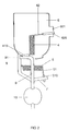
- FIG 6 is an electric incandescent lamp according to the first embodiment of the invention shown schematically.
- This bulb is a so-called single-filament halogen incandescent lamp, which is equipped with a filament and is provided for a motor vehicle headlight.
- This halogen bulb has a glass lamp vessel 60, which is sealed by means of a squeezing foot 61 is. The squeezing foot 61 is fixed in a base 62.
- a filament made of tungsten wire 63 arranged and aligned parallel to the lamp vessel axis.
- the filament 63 has two helical outlets 631, 632 running perpendicular to its winding axis each with a molybdenum existing power supply wire 64, 65 are welded.
- the power supply wires 64, 65 are over the pinch 61st led out of the lamp vessel 60 and each with an electrical connection 66 and 67 of the halogen incandescent lamp electrically connected.
- FIG. 1 shows details of the helical suspension of the incandescent filament 63 in FIG. 6 pictured halogen bulb.
- the first filament exit 631 of the filament 63 is wrapped with a molybdenum foil 633 and welded to the power supply wire 64.
- the second spiral outlet 632 of the filament 63 is also provided with a Molybdenum foil 634 wrapped and with the angled end 651 of the power supply wire 65 welded.
- the angled end 651 of the power supply wire 65 and the second filament exit 632 of the filament 63 are in a common Plane disposed perpendicular to the winding axis of the filament 63.
- FIGs 2 to 4 show different views of an inventive Spiral suspension for a so-called two-filament halogen bulb, with two Incandescent is equipped and provided for a motor vehicle headlight is.
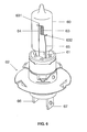
- a halogen incandescent lamp is shown schematically.
- These Halogen incandescent lamp has a substantially cylindrical, glassy lamp vessel 1, which is gas-tightly closed by means of a presser foot 1a. The top of the lamp vessel 1 is provided with an opaque coating 1b. Of the Pinch 1a is fixed in the base 2, with three electrical connections. 3 Is provided.
- the lamp vessel 1 Within the lamp vessel 1 are an axial with respect to the lamp vessel axis oriented first filament 4, the so-called auxiliary filament 4, and a second filament 5 aligned transversely to the lamp vessel axis so-called main coil 5, arranged.
- the auxiliary coil 4 is partially of a Shading device 6, which is hereinafter called dimming cap 6, surrounded. It is used to produce the low beam or the daytime running light in one Motor vehicle, while the main coil 5 is used to generate the high beam.
- the Spiral suspension for the two filament 4, 5 consists of the Abblendkappe. 6 and three power supply wires 7, 8 and 9 and the quartz glass beam 10, in the power supply wires 7, 8 and 9 are melted.
- These power supply wires 7 to 9 are passed through the pinch 1a and each with an electrical connection 3 of the halogen incandescent lamp electrically connected.
- the three power supply wires 7 to 9 are through the quartz glass bar 10 in a common plane perpendicular to the winding axis of the main coil 5 fixed.
- FIG. 5 Details of the coil suspension of the illustrated in Figure 5 halogen bulb according to of the second embodiment of the invention are in the figures 2 to 4 shown.
- the first, with a molybdenum foil 510 wrapped Wendelabgang 51 of Main coil 5 is provided with an angled end of the first power supply wire 7 welded.
- the other coil end 52 sheathed with a molybdenum foil 520 the main coil 5 is welded to the second power supply wire 8, on which also the anti-dazzle device 6 is fixed by a welded connection.
- the first, with a molybdenum foil 410 wrapped coil outlet 41 of the auxiliary coil 4 runs transverse, substantially perpendicular to the winding axis of the auxiliary spiral 4 and is with the approximately right angle angled end 91 of the third power supply wire 9 welded.
- the angled end 91 of the third power supply wire 9 and the first spiral outlet 41 of the auxiliary coil 4 are in a common Plane arranged perpendicular to the winding axis of the auxiliary coil 4.
- the angled End 91 has a length of about 3 mm.
- the second, with a molybdenum foil 420 wrapped Wendelabgang 42 is formed with a formed on the Abblendkappe 6 tab 601 welded.
Landscapes
- Non-Portable Lighting Devices Or Systems Thereof (AREA)
- Resistance Heating (AREA)
- Discharge Lamp (AREA)
- Electrochromic Elements, Electrophoresis, Or Variable Reflection Or Absorption Elements (AREA)
- Surgical Instruments (AREA)
- Cable Accessories (AREA)
- Wire Processing (AREA)
Abstract
Description
- Figur 1
- Eine Seitenansicht einer Wendelaufhängung für eine elektrische Glühlampe gemäß des ersten Ausführungsbeispiels der Erfindung
- Figur 2
- Eine erste Seitenansicht einer Wendelaufhängung für eine elektrische Glühlampe gemäß des zweiten Ausführungsbeispiels der Erfindung
- Figur 3
- Eine zweite Seitenansicht der in Figur 2 abgebildeten Wendelaufhängung in einer um 90 Grad gedrehten Ansicht
- Figur 4
- Eine Draufsicht auf die in Figur 2 und 3 abgebildeten Wendelaufhängung
- Figur 5
- Eine Seitenansicht einer Halogenglühlampe, die mit der in den Figuren 2 bis 3 abgebildeten Wendelaufhängung ausgestattet werden kann
- Figur 6
- Eine Seitenansicht einer Halogenglühlampe gemäß des ersten Ausführungsbeispiels der Erfindung, die mit der in Figur 1 abgebildeten Wendelaufhängung ausgestattet ist
Claims (4)
- Elektrische Glühlampe mit mindestens einer innerhalb eines Lampengefäßes (60) angeordneten Glühwendel (63) und Stromzuführungen (64, 65) für die Glühwendel (63), wobei mindestens eine der Stromzuführungen (65) ein abgewinkeltes Ende (651) aufweist, das mit einem quer zur Wickelachse der mindestens einen Glühwendel (63) verlaufenden Wendelabgang (632) der mindestens einen Glühwendel verbunden ist,
dadurch gekennzeichnet, dass das abgewinkelte Ende (651) und der Wendelabgang (632) der mindestens einen Glühwendel (63) in einer Ebene quer zur Wickelachse der mindestens einen Glühwendel (63) angeordnet sind. - Elektrische Glühlampe nach Anspruch 1, dadurch gekennzeichnet, dass die Ebene im wesentlichen senkrecht zur Wickelachse der mindestens einen Glühwendel (63) angeordnet ist.
- Elektrische Glühlampe nach Anspruch 1, dadurch gekennzeichnet, dass die Stromzuführung (65) als Draht ausgebildet ist.
- Elektrische Glühlampe nach einem oder mehreren der Ansprüche 1 bis 3, dadurch gekennzeichnet, dass die elektrische Glühlampe eine Fahrzeugscheinwerferlampe ist.
Applications Claiming Priority (2)
| Application Number | Priority Date | Filing Date | Title |
|---|---|---|---|
| DE102004004017 | 2004-01-22 | ||
| DE102004004017A DE102004004017A1 (de) | 2004-01-22 | 2004-01-22 | Elektrische Glühlampe |
Publications (3)
| Publication Number | Publication Date |
|---|---|
| EP1564789A2 true EP1564789A2 (de) | 2005-08-17 |
| EP1564789A3 EP1564789A3 (de) | 2008-01-23 |
| EP1564789B1 EP1564789B1 (de) | 2008-11-05 |
Family
ID=34683964
Family Applications (1)
| Application Number | Title | Priority Date | Filing Date |
|---|---|---|---|
| EP04030342A Expired - Lifetime EP1564789B1 (de) | 2004-01-22 | 2004-12-21 | Elektrische Glühlampe |
Country Status (9)
| Country | Link |
|---|---|
| US (1) | US20050162091A1 (de) |
| EP (1) | EP1564789B1 (de) |
| JP (1) | JP4910108B2 (de) |
| KR (1) | KR101119388B1 (de) |
| CN (1) | CN100555560C (de) |
| AT (1) | ATE413689T1 (de) |
| CA (1) | CA2493844A1 (de) |
| DE (2) | DE102004004017A1 (de) |
| ES (1) | ES2314333T3 (de) |
Cited By (1)
| Publication number | Priority date | Publication date | Assignee | Title |
|---|---|---|---|---|
| WO2008074638A3 (de) * | 2006-12-19 | 2009-01-15 | Osram Gmbh | Schweisshilfe für eine glühwendel |
Families Citing this family (2)
| Publication number | Priority date | Publication date | Assignee | Title |
|---|---|---|---|---|
| CN201508829U (zh) * | 2009-08-27 | 2010-06-16 | 杨范文 | 一种灯丝 |
| KR200452390Y1 (ko) * | 2010-08-13 | 2011-02-28 | 에스에스라이팅 주식회사 | 진동 내구성이 강화된 자동차용 할로겐 전조등 |
Family Cites Families (14)
| Publication number | Priority date | Publication date | Assignee | Title |
|---|---|---|---|---|
| US3310702A (en) * | 1965-06-14 | 1967-03-21 | Robert N Falge | Vehicle headlamp with improved filament mounting structure |
| US3858086A (en) * | 1973-10-29 | 1974-12-31 | Gte Sylvania Inc | Extended life, double coil incandescent lamp |
| US4994707A (en) * | 1988-09-22 | 1991-02-19 | Patent-Treuhand Gesellschaft fur elektrische Glum.b.H. | Vibration-resistant single-ended halogen incandescent lamp |
| US5239231A (en) * | 1991-03-05 | 1993-08-24 | Cooper Industries, Inc. | Filament attachment method for dual filament halogen lamp having a common ground connection |
| JPH0869779A (ja) * | 1994-08-31 | 1996-03-12 | Toshiba Lighting & Technol Corp | 白熱電球およびこれを用いた反射形照明装置ならびに車両用前照灯 |
| JPH08255596A (ja) * | 1995-03-20 | 1996-10-01 | Matsushita Electron Corp | ハロゲン電球 |
| JP3532011B2 (ja) * | 1995-03-31 | 2004-05-31 | ハリソン東芝ライティング株式会社 | 電球、車両用前照灯および車両 |
| JPH08306343A (ja) * | 1995-04-28 | 1996-11-22 | Koito Mfg Co Ltd | 白熱電球 |
| JP3771322B2 (ja) * | 1996-06-04 | 2006-04-26 | 本田技研工業株式会社 | 自動車用電球 |
| DE19707245A1 (de) * | 1997-02-25 | 1998-08-27 | Patent Treuhand Ges Fuer Elektrische Gluehlampen Mbh | Verfahren zur Herstellung einer elektrischen Glühlampe |
| WO1998049716A1 (en) * | 1997-04-28 | 1998-11-05 | Osram Sylvania Inc. | Vehicle lamps with glare control |
| US6630770B1 (en) * | 1998-11-20 | 2003-10-07 | Ichikoh Industries, Ltd. | Automotive headlamp with support wire positioning |
| DE10145427A1 (de) * | 2001-09-14 | 2003-04-03 | Patent Treuhand Ges Fuer Elektrische Gluehlampen Mbh | Glühlampe für Kraftfahrzeugscheinwerfer |
| US6856090B2 (en) * | 2001-10-23 | 2005-02-15 | Federal-Mogul Worldwide, Inc. | Incandescent halogen lamp having flattened filament support leads |
-
2004
- 2004-01-22 DE DE102004004017A patent/DE102004004017A1/de not_active Withdrawn
- 2004-12-21 AT AT04030342T patent/ATE413689T1/de active
- 2004-12-21 ES ES04030342T patent/ES2314333T3/es not_active Expired - Lifetime
- 2004-12-21 EP EP04030342A patent/EP1564789B1/de not_active Expired - Lifetime
- 2004-12-21 DE DE502004008402T patent/DE502004008402D1/de not_active Expired - Lifetime
-
2005
- 2005-01-13 KR KR1020050003166A patent/KR101119388B1/ko not_active Expired - Fee Related
- 2005-01-14 US US11/034,883 patent/US20050162091A1/en not_active Abandoned
- 2005-01-21 CA CA002493844A patent/CA2493844A1/en not_active Abandoned
- 2005-01-21 CN CNB2005100046792A patent/CN100555560C/zh not_active Expired - Fee Related
- 2005-01-24 JP JP2005015925A patent/JP4910108B2/ja not_active Expired - Fee Related
Cited By (2)
| Publication number | Priority date | Publication date | Assignee | Title |
|---|---|---|---|---|
| WO2008074638A3 (de) * | 2006-12-19 | 2009-01-15 | Osram Gmbh | Schweisshilfe für eine glühwendel |
| US8212476B2 (en) | 2006-12-19 | 2012-07-03 | Osram Ag | Welding aid for a spiral-wound filament |
Also Published As
| Publication number | Publication date |
|---|---|
| CA2493844A1 (en) | 2005-07-22 |
| JP2005209655A (ja) | 2005-08-04 |
| ATE413689T1 (de) | 2008-11-15 |
| DE502004008402D1 (de) | 2008-12-18 |
| KR20050076740A (ko) | 2005-07-27 |
| KR101119388B1 (ko) | 2012-03-06 |
| EP1564789B1 (de) | 2008-11-05 |
| EP1564789A3 (de) | 2008-01-23 |
| CN1645558A (zh) | 2005-07-27 |
| US20050162091A1 (en) | 2005-07-28 |
| JP4910108B2 (ja) | 2012-04-04 |
| ES2314333T3 (es) | 2009-03-16 |
| CN100555560C (zh) | 2009-10-28 |
| DE102004004017A1 (de) | 2005-08-25 |
Similar Documents
| Publication | Publication Date | Title |
|---|---|---|
| EP1667205B1 (de) | Fahrzeugscheinwerferlampe | |
| EP0910867B1 (de) | Verfahren zur herstellung einer elektrischen glühlampe | |
| EP1294013B1 (de) | Glühlampe für Kraftfahrzeugscheinwerfer | |
| EP2087506B1 (de) | Halogenglühlampe | |
| DE19544012A1 (de) | Elektrische Glühlampe mit Abblendkappe und Verfahren zur Herstellung einer derartigen Lampe sowie Abblendkappe für eine elektrische Glühlampe | |
| EP1564789B1 (de) | Elektrische Glühlampe | |
| EP1363315B1 (de) | Glühlampe für Kraftfahrzeugscheinwerfer | |
| WO2013120683A1 (de) | Glühfaden für elektrische lampen und elektrische lampe sowie herstellungsverfahren für einen glühfaden | |
| EP2095399B1 (de) | Zweiwendellampe | |
| EP2122664B1 (de) | Halogenglühlampe | |
| EP1560258A2 (de) | Glühlampe für Fahrzeugscheinwerfer | |
| DE102004040415A1 (de) | Elektrische Glühlampe für Fahrzeugscheinwerfer | |
| EP1447837A2 (de) | Glühlampe für Fahrzeugscheinwerfer | |
| EP0914674B1 (de) | Elektrische lampe | |
| DE102005048444A1 (de) | Scheinwerferlampe | |
| EP1667203A2 (de) | Elektrische Glühlampe | |
| EP1684331A1 (de) | Elektrische Glühlampe | |
| EP2465134A1 (de) | Halogenglühlampe für fahrzeugscheinwerfer | |
| DE10359152A1 (de) | Glühlampe für Fahrzeugscheinwerfer | |
| DE19538497A1 (de) | Elektrische Lampe und Herstellungsverfahren für eine elektrische Lampe | |
| DE29612757U1 (de) | Einseitig verschlossene elektrische Glühlampe | |
| EP0784335A1 (de) | Vibrationsfeste elektrische Glühlampe | |
| DE102006060008A1 (de) | Lampe mit verbesserter Quetschungsgeometrie | |
| DE202006019131U1 (de) | Lampe | |
| DE2401541A1 (de) | Elektrische gluehlampe, insbesondere halogengluehlampe fuer kraftfahrzeuge |
Legal Events
| Date | Code | Title | Description |
|---|---|---|---|
| PUAI | Public reference made under article 153(3) epc to a published international application that has entered the european phase |
Free format text: ORIGINAL CODE: 0009012 |
|
| AK | Designated contracting states |
Kind code of ref document: A2 Designated state(s): AT BE BG CH CY CZ DE DK EE ES FI FR GB GR HU IE IS IT LI LT LU MC NL PL PT RO SE SI SK TR |
|
| AX | Request for extension of the european patent |
Extension state: AL BA HR LV MK YU |
|
| PUAL | Search report despatched |
Free format text: ORIGINAL CODE: 0009013 |
|
| AK | Designated contracting states |
Kind code of ref document: A3 Designated state(s): AT BE BG CH CY CZ DE DK EE ES FI FR GB GR HU IE IS IT LI LT LU MC NL PL PT RO SE SI SK TR |
|
| AX | Request for extension of the european patent |
Extension state: AL BA HR LV MK YU |
|
| 17P | Request for examination filed |
Effective date: 20080220 |
|
| GRAP | Despatch of communication of intention to grant a patent |
Free format text: ORIGINAL CODE: EPIDOSNIGR1 |
|
| GRAS | Grant fee paid |
Free format text: ORIGINAL CODE: EPIDOSNIGR3 |
|
| AKX | Designation fees paid |
Designated state(s): AT BE BG CH CY CZ DE DK EE ES FI FR GB GR HU IE IS IT LI LT LU MC NL PL PT RO SE SI SK TR |
|
| GRAA | (expected) grant |
Free format text: ORIGINAL CODE: 0009210 |
|
| AK | Designated contracting states |
Kind code of ref document: B1 Designated state(s): AT BE BG CH CY CZ DE DK EE ES FI FR GB GR HU IE IS IT LI LT LU MC NL PL PT RO SE SI SK TR |
|
| REG | Reference to a national code |
Ref country code: GB Ref legal event code: FG4D Free format text: NOT ENGLISH |
|
| REG | Reference to a national code |
Ref country code: CH Ref legal event code: EP |
|
| REG | Reference to a national code |
Ref country code: IE Ref legal event code: FG4D Free format text: LANGUAGE OF EP DOCUMENT: GERMAN |
|
| REF | Corresponds to: |
Ref document number: 502004008402 Country of ref document: DE Date of ref document: 20081218 Kind code of ref document: P |
|
| REG | Reference to a national code |
Ref country code: SE Ref legal event code: TRGR |
|
| REG | Reference to a national code |
Ref country code: ES Ref legal event code: FG2A Ref document number: 2314333 Country of ref document: ES Kind code of ref document: T3 |
|
| LTIE | Lt: invalidation of european patent or patent extension |
Effective date: 20081105 |
|
| PG25 | Lapsed in a contracting state [announced via postgrant information from national office to epo] |
Ref country code: LT Free format text: LAPSE BECAUSE OF FAILURE TO SUBMIT A TRANSLATION OF THE DESCRIPTION OR TO PAY THE FEE WITHIN THE PRESCRIBED TIME-LIMIT Effective date: 20081105 |
|
| PG25 | Lapsed in a contracting state [announced via postgrant information from national office to epo] |
Ref country code: SI Free format text: LAPSE BECAUSE OF FAILURE TO SUBMIT A TRANSLATION OF THE DESCRIPTION OR TO PAY THE FEE WITHIN THE PRESCRIBED TIME-LIMIT Effective date: 20081105 Ref country code: PL Free format text: LAPSE BECAUSE OF FAILURE TO SUBMIT A TRANSLATION OF THE DESCRIPTION OR TO PAY THE FEE WITHIN THE PRESCRIBED TIME-LIMIT Effective date: 20081105 Ref country code: IS Free format text: LAPSE BECAUSE OF FAILURE TO SUBMIT A TRANSLATION OF THE DESCRIPTION OR TO PAY THE FEE WITHIN THE PRESCRIBED TIME-LIMIT Effective date: 20090305 Ref country code: FI Free format text: LAPSE BECAUSE OF FAILURE TO SUBMIT A TRANSLATION OF THE DESCRIPTION OR TO PAY THE FEE WITHIN THE PRESCRIBED TIME-LIMIT Effective date: 20081105 |
|
| REG | Reference to a national code |
Ref country code: IE Ref legal event code: FD4D |
|
| PG25 | Lapsed in a contracting state [announced via postgrant information from national office to epo] |
Ref country code: BG Free format text: LAPSE BECAUSE OF FAILURE TO SUBMIT A TRANSLATION OF THE DESCRIPTION OR TO PAY THE FEE WITHIN THE PRESCRIBED TIME-LIMIT Effective date: 20090205 Ref country code: DK Free format text: LAPSE BECAUSE OF FAILURE TO SUBMIT A TRANSLATION OF THE DESCRIPTION OR TO PAY THE FEE WITHIN THE PRESCRIBED TIME-LIMIT Effective date: 20081105 Ref country code: EE Free format text: LAPSE BECAUSE OF FAILURE TO SUBMIT A TRANSLATION OF THE DESCRIPTION OR TO PAY THE FEE WITHIN THE PRESCRIBED TIME-LIMIT Effective date: 20081105 Ref country code: MC Free format text: LAPSE BECAUSE OF NON-PAYMENT OF DUE FEES Effective date: 20081231 Ref country code: IE Free format text: LAPSE BECAUSE OF FAILURE TO SUBMIT A TRANSLATION OF THE DESCRIPTION OR TO PAY THE FEE WITHIN THE PRESCRIBED TIME-LIMIT Effective date: 20081105 Ref country code: RO Free format text: LAPSE BECAUSE OF FAILURE TO SUBMIT A TRANSLATION OF THE DESCRIPTION OR TO PAY THE FEE WITHIN THE PRESCRIBED TIME-LIMIT Effective date: 20081105 |
|
| REG | Reference to a national code |
Ref country code: CH Ref legal event code: PL |
|
| REG | Reference to a national code |
Ref country code: HU Ref legal event code: AG4A Ref document number: E005381 Country of ref document: HU |
|
| PG25 | Lapsed in a contracting state [announced via postgrant information from national office to epo] |
Ref country code: CZ Free format text: LAPSE BECAUSE OF FAILURE TO SUBMIT A TRANSLATION OF THE DESCRIPTION OR TO PAY THE FEE WITHIN THE PRESCRIBED TIME-LIMIT Effective date: 20081105 Ref country code: PT Free format text: LAPSE BECAUSE OF FAILURE TO SUBMIT A TRANSLATION OF THE DESCRIPTION OR TO PAY THE FEE WITHIN THE PRESCRIBED TIME-LIMIT Effective date: 20090406 |
|
| PLBE | No opposition filed within time limit |
Free format text: ORIGINAL CODE: 0009261 |
|
| STAA | Information on the status of an ep patent application or granted ep patent |
Free format text: STATUS: NO OPPOSITION FILED WITHIN TIME LIMIT |
|
| PG25 | Lapsed in a contracting state [announced via postgrant information from national office to epo] |
Ref country code: SK Free format text: LAPSE BECAUSE OF FAILURE TO SUBMIT A TRANSLATION OF THE DESCRIPTION OR TO PAY THE FEE WITHIN THE PRESCRIBED TIME-LIMIT Effective date: 20081105 |
|
| 26N | No opposition filed |
Effective date: 20090806 |
|
| PG25 | Lapsed in a contracting state [announced via postgrant information from national office to epo] |
Ref country code: LI Free format text: LAPSE BECAUSE OF NON-PAYMENT OF DUE FEES Effective date: 20081231 Ref country code: CH Free format text: LAPSE BECAUSE OF NON-PAYMENT OF DUE FEES Effective date: 20081231 |
|
| PG25 | Lapsed in a contracting state [announced via postgrant information from national office to epo] |
Ref country code: LU Free format text: LAPSE BECAUSE OF NON-PAYMENT OF DUE FEES Effective date: 20081221 Ref country code: CY Free format text: LAPSE BECAUSE OF FAILURE TO SUBMIT A TRANSLATION OF THE DESCRIPTION OR TO PAY THE FEE WITHIN THE PRESCRIBED TIME-LIMIT Effective date: 20081105 |
|
| PG25 | Lapsed in a contracting state [announced via postgrant information from national office to epo] |
Ref country code: TR Free format text: LAPSE BECAUSE OF FAILURE TO SUBMIT A TRANSLATION OF THE DESCRIPTION OR TO PAY THE FEE WITHIN THE PRESCRIBED TIME-LIMIT Effective date: 20081105 |
|
| PG25 | Lapsed in a contracting state [announced via postgrant information from national office to epo] |
Ref country code: GR Free format text: LAPSE BECAUSE OF FAILURE TO SUBMIT A TRANSLATION OF THE DESCRIPTION OR TO PAY THE FEE WITHIN THE PRESCRIBED TIME-LIMIT Effective date: 20090206 |
|
| REG | Reference to a national code |
Ref country code: DE Ref legal event code: R081 Ref document number: 502004008402 Country of ref document: DE Owner name: OSRAM GMBH, DE Free format text: FORMER OWNER: OSRAM GESELLSCHAFT MIT BESCHRAENKTER HAFTUNG, 81543 MUENCHEN, DE Effective date: 20111213 |
|
| PGFP | Annual fee paid to national office [announced via postgrant information from national office to epo] |
Ref country code: ES Payment date: 20121217 Year of fee payment: 9 Ref country code: SE Payment date: 20121220 Year of fee payment: 9 |
|
| REG | Reference to a national code |
Ref country code: DE Ref legal event code: R081 Ref document number: 502004008402 Country of ref document: DE Owner name: OSRAM GMBH, DE Free format text: FORMER OWNER: OSRAM AG, 81543 MUENCHEN, DE Effective date: 20130205 |
|
| PGFP | Annual fee paid to national office [announced via postgrant information from national office to epo] |
Ref country code: AT Payment date: 20121212 Year of fee payment: 9 |
|
| PGFP | Annual fee paid to national office [announced via postgrant information from national office to epo] |
Ref country code: BE Payment date: 20121219 Year of fee payment: 9 |
|
| PGFP | Annual fee paid to national office [announced via postgrant information from national office to epo] |
Ref country code: NL Payment date: 20121220 Year of fee payment: 9 |
|
| REG | Reference to a national code |
Ref country code: DE Ref legal event code: R081 Ref document number: 502004008402 Country of ref document: DE Owner name: OSRAM GMBH, DE Free format text: FORMER OWNER: OSRAM GMBH, 81543 MUENCHEN, DE Effective date: 20130823 |
|
| BERE | Be: lapsed |
Owner name: PATENT-TREUHAND-GESELLSCHAFT FUR ELEKTRISCHE GLUH Effective date: 20131231 |
|
| REG | Reference to a national code |
Ref country code: NL Ref legal event code: V1 Effective date: 20140701 |
|
| REG | Reference to a national code |
Ref country code: SE Ref legal event code: EUG |
|
| REG | Reference to a national code |
Ref country code: AT Ref legal event code: MM01 Ref document number: 413689 Country of ref document: AT Kind code of ref document: T Effective date: 20131221 |
|
| PG25 | Lapsed in a contracting state [announced via postgrant information from national office to epo] |
Ref country code: SE Free format text: LAPSE BECAUSE OF NON-PAYMENT OF DUE FEES Effective date: 20131222 |
|
| PG25 | Lapsed in a contracting state [announced via postgrant information from national office to epo] |
Ref country code: NL Free format text: LAPSE BECAUSE OF NON-PAYMENT OF DUE FEES Effective date: 20140701 Ref country code: BE Free format text: LAPSE BECAUSE OF NON-PAYMENT OF DUE FEES Effective date: 20131231 |
|
| PG25 | Lapsed in a contracting state [announced via postgrant information from national office to epo] |
Ref country code: AT Free format text: LAPSE BECAUSE OF NON-PAYMENT OF DUE FEES Effective date: 20131221 |
|
| REG | Reference to a national code |
Ref country code: ES Ref legal event code: FD2A Effective date: 20150529 |
|
| PG25 | Lapsed in a contracting state [announced via postgrant information from national office to epo] |
Ref country code: ES Free format text: LAPSE BECAUSE OF NON-PAYMENT OF DUE FEES Effective date: 20131222 |
|
| REG | Reference to a national code |
Ref country code: FR Ref legal event code: PLFP Year of fee payment: 12 |
|
| REG | Reference to a national code |
Ref country code: FR Ref legal event code: PLFP Year of fee payment: 13 |
|
| REG | Reference to a national code |
Ref country code: FR Ref legal event code: PLFP Year of fee payment: 14 |
|
| PGFP | Annual fee paid to national office [announced via postgrant information from national office to epo] |
Ref country code: FR Payment date: 20171221 Year of fee payment: 14 Ref country code: HU Payment date: 20171212 Year of fee payment: 14 Ref country code: DE Payment date: 20171211 Year of fee payment: 14 |
|
| PGFP | Annual fee paid to national office [announced via postgrant information from national office to epo] |
Ref country code: GB Payment date: 20171221 Year of fee payment: 14 |
|
| PGFP | Annual fee paid to national office [announced via postgrant information from national office to epo] |
Ref country code: IT Payment date: 20171221 Year of fee payment: 14 |
|
| REG | Reference to a national code |
Ref country code: DE Ref legal event code: R119 Ref document number: 502004008402 Country of ref document: DE |
|
| GBPC | Gb: european patent ceased through non-payment of renewal fee |
Effective date: 20181221 |
|
| PG25 | Lapsed in a contracting state [announced via postgrant information from national office to epo] |
Ref country code: IT Free format text: LAPSE BECAUSE OF NON-PAYMENT OF DUE FEES Effective date: 20181221 Ref country code: DE Free format text: LAPSE BECAUSE OF NON-PAYMENT OF DUE FEES Effective date: 20190702 Ref country code: FR Free format text: LAPSE BECAUSE OF NON-PAYMENT OF DUE FEES Effective date: 20181231 |
|
| PG25 | Lapsed in a contracting state [announced via postgrant information from national office to epo] |
Ref country code: HU Free format text: LAPSE BECAUSE OF NON-PAYMENT OF DUE FEES Effective date: 20181222 |
|
| PG25 | Lapsed in a contracting state [announced via postgrant information from national office to epo] |
Ref country code: GB Free format text: LAPSE BECAUSE OF NON-PAYMENT OF DUE FEES Effective date: 20181221 |