EP1564443B1 - Ausrückbarer Reibradspanner - Google Patents
Ausrückbarer Reibradspanner Download PDFInfo
- Publication number
- EP1564443B1 EP1564443B1 EP05100698A EP05100698A EP1564443B1 EP 1564443 B1 EP1564443 B1 EP 1564443B1 EP 05100698 A EP05100698 A EP 05100698A EP 05100698 A EP05100698 A EP 05100698A EP 1564443 B1 EP1564443 B1 EP 1564443B1
- Authority
- EP
- European Patent Office
- Prior art keywords
- eccentric
- friction wheel
- housing
- electric motor
- eddy current
- Prior art date
- Legal status (The legal status is an assumption and is not a legal conclusion. Google has not performed a legal analysis and makes no representation as to the accuracy of the status listed.)
- Expired - Lifetime
Links
- 230000008878 coupling Effects 0.000 description 10
- 238000010168 coupling process Methods 0.000 description 10
- 238000005859 coupling reaction Methods 0.000 description 10
- 230000005540 biological transmission Effects 0.000 description 9
- 230000006835 compression Effects 0.000 description 1
- 238000007906 compression Methods 0.000 description 1
- 238000006073 displacement reaction Methods 0.000 description 1
- 230000000630 rising effect Effects 0.000 description 1
- XLYOFNOQVPJJNP-UHFFFAOYSA-N water Substances O XLYOFNOQVPJJNP-UHFFFAOYSA-N 0.000 description 1
Images


Classifications
-
- F—MECHANICAL ENGINEERING; LIGHTING; HEATING; WEAPONS; BLASTING
- F16—ENGINEERING ELEMENTS AND UNITS; GENERAL MEASURES FOR PRODUCING AND MAINTAINING EFFECTIVE FUNCTIONING OF MACHINES OR INSTALLATIONS; THERMAL INSULATION IN GENERAL
- F16H—GEARING
- F16H13/00—Gearing for conveying rotary motion with constant gear ratio by friction between rotary members
- F16H13/10—Means for influencing the pressure between the members
-
- F—MECHANICAL ENGINEERING; LIGHTING; HEATING; WEAPONS; BLASTING
- F01—MACHINES OR ENGINES IN GENERAL; ENGINE PLANTS IN GENERAL; STEAM ENGINES
- F01P—COOLING OF MACHINES OR ENGINES IN GENERAL; COOLING OF INTERNAL-COMBUSTION ENGINES
- F01P5/00—Pumping cooling-air or liquid coolants
- F01P5/10—Pumping liquid coolant; Arrangements of coolant pumps
- F01P5/12—Pump-driving arrangements
-
- F—MECHANICAL ENGINEERING; LIGHTING; HEATING; WEAPONS; BLASTING
- F01—MACHINES OR ENGINES IN GENERAL; ENGINE PLANTS IN GENERAL; STEAM ENGINES
- F01P—COOLING OF MACHINES OR ENGINES IN GENERAL; COOLING OF INTERNAL-COMBUSTION ENGINES
- F01P5/00—Pumping cooling-air or liquid coolants
- F01P5/14—Safety means against, or active at, failure of coolant-pumps drives, e.g. shutting engine down; Means for indicating functioning of coolant pumps
-
- F—MECHANICAL ENGINEERING; LIGHTING; HEATING; WEAPONS; BLASTING
- F16—ENGINEERING ELEMENTS AND UNITS; GENERAL MEASURES FOR PRODUCING AND MAINTAINING EFFECTIVE FUNCTIONING OF MACHINES OR INSTALLATIONS; THERMAL INSULATION IN GENERAL
- F16H—GEARING
- F16H7/00—Gearings for conveying rotary motion by endless flexible members
- F16H7/02—Gearings for conveying rotary motion by endless flexible members with belts; with V-belts
Definitions
- Reibradspanner serve to press a friction wheel in a friction gear to its rotation partner, usually a drive wheel.
- the friction wheel of Reibradspanners is usually pressed by spring force to the drive wheel.
- the spring force can be generated by tension or compression springs, but also by a coil spring which exerts a torque in the pivot point of a boom. On the boom, the friction wheel is attached to the opposite end of the pivot.
- Such Reibradspanner cause a permanent engagement of the friction wheel with the drive wheel.
- Disengageable Reibradspanner serve to reversibly interrupt the frictional engagement between the friction wheel and the drive wheel, for example, ancillary components of a motor engine, such as water pump, power steering pump, etc. to be able to switch off when not in use, to save energy.
- the coupling or uncoupling of the friction wheel from the drive wheel must on the one hand run fast so that unnecessary wear of the friction wheel is avoided, on the other hand, the contact pressure of the friction wheel to the drive wheel must be sufficient to transmit a required nominal torque and to allow a smooth, low-vibration running of the transmission.
- An internal, previously unpublished approach has a friction wheel receiver formed as an adjustable, guided cantilever which engages the rotatably mounted friction wheel by linear displacement of the cantilever out of or out of the housing into a drive wheel or decoupling from the drive wheel.
- the boom is displaced by being pushed out of the housing via the rotating eccentric of the adjusting device or pulled into the housing.
- the rotation of the eccentric is done by the electric motor.
- the return spring ensures the reverse rotation when the current on the electric motor is switched off.
- the invention is therefore an object of the invention to provide an eccentric drive for an adjustable Reibradspanner that does not hinder the reverse rotation of the eccentric in the de-energized state and can be operated with a simple, inexpensive electric motor.
- the adjusting device has an eddy current coupling, wherein the electric motor of the adjusting device via the eddy current coupling and the gearbox is in operative connection with the eccentric.
- This erfmdungswashe arrangement has the advantage that the electric motor acts on the eccentric via the eddy current coupling. If the current at the electric motor and the eddy current coupling is switched off, a complete mechanical decoupling of electric motor and eccentric can be achieved.
- a gear transmission is arranged between eddy current coupling and eccentric of the adjusting device.
- the interposition of the transmission can be used with a sufficiently large reduction and a cost-effective high-speed electric motor with low torque.
- the use of an expensive, low-speed electric motor with high torque, which drives the eccentric directly, is therefore not required.
- Fig. 1 shows a Reibradspanner 1 according to the invention in a three-dimensional representation with a housing 2 and a boom 3, on whose side facing away from the housing 2, a friction wheel 4 is rotatably mounted.
- the housing 2 receives an eccentric 5, which is pushed onto a tubular, rising from the center of the housing 2 connecting piece 6 of the housing 2 and engages with its lower end 7 in a bore or eye 8 of the boom 3.
- an electric motor 9 is arranged within the tubular housing stub 6, which an electric motor 9 is arranged. Above the electric motor 9, an eddy current clutch 10 is mounted, which has a pinion 11 on its upper side.
- the pinion 11 is connected via a gear transmission 12 with the eccentric 5 in operative connection by one of the gears 13 of the gear mechanism 12 engages in an internal toothing 14 of the eccentric 5, on the inner side 15 of the annular, in diameter relative to the eccentric 5 extended upper part 16th of the eccentric 5 is attached.
- a helical return spring 17 is externally around the eccentric 5 around and is attached at one end 18 to the eddy current coupling 9, with the other end 19 to the boom 3.
- the boom is guided linearly displaceable in an opening 20 of the housing 2.
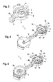
- FIG. 3 shows the opened housing 2 with an electric motor 9 mounted in a rotationally fixed manner inside the housing stub 6.
- the electric motor 9 has a long, upwardly projecting shaft 21.
- a bearing pin 22 for receiving the friction wheel 4 is arranged at the end of the cantilevered housing 2.
- Fig. 4 shows the opened housing 2 with mounted return spring 17 and deferred eccentric 5.
- the eddy current coupling 10 is above the electric motor 9 within the Housing socket 6 mounted and rotatably connected to the long shaft 21 of the electric motor 9.
- the friction wheel 4 is rotatably mounted on the bearing pin 22.
- the eddy current clutch 10 is effective only during rotation of the shaft 21.
- the pinion 11 transmits the rotation of the eddy current clutch 10 via the gear transmission 12 and the internal teeth 14 of the eccentric 5 on the eccentric 5.
- the eccentric 5 rotates in the eye 8 of the boom 3.
- the boom 3 is characterized in the opening 20 of the housing. 2 displaced linearly out of the housing 2 out.
Landscapes
- Engineering & Computer Science (AREA)
- General Engineering & Computer Science (AREA)
- Mechanical Engineering (AREA)
- Jib Cranes (AREA)
- Devices For Conveying Motion By Means Of Endless Flexible Members (AREA)
- Gear Transmission (AREA)
- One-Way And Automatic Clutches, And Combinations Of Different Clutches (AREA)
Description
- Aus der DE 373816 ist einer ausrückbaren Reibradspanner mit den Merkmalen des Oberbegriffes des Anspruches 1 bekannt.
- Die Erfindung betrifft einen ausrückbaren Reibradspanner mit folgenden Merkmalen:
- ein Gehäuse
- eine Reibradaufnahme, die als verstellbarer linear geführter Ausleger ausgebildet ist,
- ein an der Reibradaufnahme drehbar befestigtes Reibrad,
- der Ausleger ist durch einen drehbaren Exzenter linear in das Gehäuse hinein oder aus dem Gehäuse heraus verlagerbar, wobei der Exzenter innerhalb einer Bohrung des Auslegers angeordnet ist und mit diesem in Wirkverbindung steht,
- der Exzenter ist durch eine Verstelleinrichtung verdrehbar,
- die Verstelleinrichtung weist einen Elektromotor und eine Rückholfeder auf, wobei der Exzenter durch den Elektromotor in eine Drehrichtung, durch die Rückholfeder in die andere Drehrichtung verdrehbar ist.
- Reibradspanner dienen dazu, ein Reibrad in einem Reibradgetriebe an seinen Rotationspartner, meist ein Antriebsrad zu drücken. Dabei ist das Reibrad des Reibradspanners meist durch Federkraft an das Antriebsrad gepresst. Die Federkraft kann durch Zug- oder Druckfedern erzeugt werden, aber auch durch eine Spiralfeder, die im Drehpunkt eines Auslegers ein Drehmoment ausübt. An dem Ausleger ist an dem dem Drehpunkt gegenüber liegenden Ende das Reibrad angebracht. Derartige Reibradspanner bewirken einen dauernden Eingriff des Reibrades mit dem Antriebsrad.
- Ausrückbare Reibradspanner dienen dazu, den Reibschluss zwischen Reibrad und Antriebsrad reversibel zu unterbrechen, um zum Beispiel Nebenaggregate eines Kraftfahr zeugmotors, wie Wasserpumpe, Servolenkungspumpe etc. bei Nichtgebrauch abschalten zu können, um Energie zu sparen.
- Das An- bzw. Abkoppeln des Reibrades vom Antriebsrad muss einerseits schnell ablaufen, damit unnötiger Verschleiß des Reibrades vermieden wird, andererseits muss die Anpressung des Reibrades an das Antriebsrad ausreichen, ein gefordertes Nenndrehmoment zu übertragen und einen gleichmäßigen, drehschwingungsarmen Lauf des Getriebes zu ermöglichen.
- Ein interner, bisher nicht veröffentlichter Lösungsansatz weist eine als verstellbarer, geführter Ausleger ausgebildete Reibradaufnahme auf, die das drehbar befestigte Reibrad durch lineare Verlagerung des Auslegers aus einem Gehäuse heraus oder in das Gehäuse hinein mit einem Antriebsrad in Eingriff bringt oder vom Antriebsrad abkoppelt. Der Ausleger wird dadurch verlagert, dass er über den sich drehenden Exzenter der Verstelleinrichtung aus dem Gehäuse herausgeschoben oder in das Gehäuse hineingezogen wird. Die Verdrehung des Exzenters geschieht durch den Elektromotor. Die Rückstellfeder sorgt bei Abschaltung des Stromes am Elektromotor für die Rückdrehung.
- Diese Anordnung setzt einen präzise arbeitenden, sehr langsam drehenden Elektromotor mit hohem Drehmoment voraus. Außerdem muß der Motor für die Rückdrehung des Exzenters bei Ausschalten des Stromes praktisch bremsmomentfrei sein, da die Rückholfeder sonst zu stark ausgelegt werden muß oder eine zuverlässige Abkoppelung des Reibrades vom Antriebsrad nicht gewährleistet ist. Die Bremsmomentfreiheit ist jedoch auch bei sehr aufwendigen Elektromotoren nicht vollständig gewährleistet. Außerdem verursachen langsamdrehende Elektromotore mit hohem Drehmoment sehr hohe Kosten.
- Der Erfindung liegt daher die Aufgabe zugrunde, einen Exzenterantrieb für einen verstellbaren Reibradspanner zu schaffen, der im stromlosen Zustand die Rückdrehung des Exzenters nicht behindert und mit einem einfachen, kostengünstigen Elektromotor betrieben werden kann.
- Diese Aufgabe wird dadurch gelöst, dass die Verstelleinrichtung eine Wirbelstromkupplung aufweist, wobei der Elektromotor der Verstelleinrichtung über die Wirbelstromkupplung und das Getriebe mit dem Exzenter in Wirkverbindung steht.
- Diese erfmdungsgemäße Anordnung hat den Vorteil, dass der Elektromotor über die Wirbelstromkupplung auf den Exzenter einwirkt. Wird der Strom am Elektromotor und der Wirbelstromkupplung abgeschaltet, ist eine vollständige mechanische Entkopplung von Elektromotor und Exzenter erreichbar.
- In einer weiteren Ausbildung der Erfindung ist zwischen Wirbelstromkupplung und Exzenter der Verstelleinrichtung ein Zahnradgetriebe angeordnet.
- Durch die Zwischenschaltung des Getriebes kann bei genügend großer Untersetzung auch ein kostengünstiger schnelllaufender Elektromotor mit geringem Drehmoment eingesetzt werden. Dabei sind auch während des Verstellens, also während der Drehung des Motors, die Abweichungen von einem gleichmäßigen Lauf des Motors durch die Verwendung des Getriebes und der Wirbelstromkupplung von geringem Einfluss auf die Funktion des Reibradspanners. Die Verwendung eines teuren, langsamlaufenden Elektromotors mit hohem Drehmoment, der den Exzenter direkt antreibt, ist daher nicht erforderlich.
- Anhand der Zeichnung wird nachstehend ein Ausführungsbeispiel der Erfindung näher erläutert. Es zeigt
- Fig. 1
- einen Reibradspanner in dreidimensionaler Darstellung als aufgeschnittenes Modell,
- Fig. 2
- den Reibradspanner aus Fig. 1 als Querschnitt
- Fig. 3
- das Gehäuse des Reibradspanners mit einem Elektromotor ohne Kupplung, Getriebe und Verstelleinheit,
- Fig. 4
- das Gehäuse aus Fig. 3 mit montierter Kupplung, Rückholfeder und Verstelleinheit und
- Fig. 5
- das komplett montierte Gehäuse des Reibradspanners.
- Fig. 1 zeigt einen erfindungsgemäßen Reibradspanner 1 in einer dreidimensionalen Darstellung mit einem Gehäuse 2 und einem Ausleger 3, an dessen dem Gehäuse 2 abgewandten Seite ein Reibrad 4 drehbar gelagert ist. Das Gehäuse 2 nimmt einen Exzenter 5 auf, der auf einen rohrförmigen, aus der Mitte des Gehäuses 2 aufragenden Stutzen 6 des Gehäuses 2 aufgeschoben ist und mit seinem unteren Ende 7 in eine Bohrung oder ein Auge 8 des Auslegers 3 greift. Innerhalb des rohrförmigen Gehäusestutzens 6 ist ein Elektromotor 9 angeordnet. Oberhalb des Elektromotors 9 ist eine Wirbelstromkupplung 10 angebracht, die an ihrer Oberseite ein Ritzel 11 aufweist. Das Ritzel 11 steht über ein Zahnradgetriebe 12 mit dem Exzenter 5 in Wirkverbindung, indem eines der Zahnräder 13 des Zahnradgetriebes 12 in eine Innenverzahnung 14 des Exzenters 5 greift, die an der Innenseite 15 des ringförmigen, im Durchmesser gegenüber dem Exzenter 5 erweiterten oberen Teil 16 des Exzenters 5 angebracht ist. Eine spiralförmige Rückholfeder 17 liegt außen um den Exzenter 5 herum und ist mit einem Ende 18 an der Wirbelstromkupplung 9, mit dem anderen Ende 19 an dem Ausleger 3 befestigt. Der Ausleger ist in einer Öffnung 20 des Gehäuses 2 linear verschieblich geführt.
- In Fig. 2 sind die genannten Einzelteile des Reibradspanners 1 noch einmal in einem Querschnitt dargestellt.
- Fig. 3 zeigt das geöffnete Gehäuse 2 mit im Inneren des Gehäusestutzens 6 drehfest angebrachten Elektromotor 9. Der Elektromotor 9 weist eine lange, nach oben herausragende Welle 21 auf. An dem dem Gehäuse 2 abgewanden Ende des Auslegers ist ein Lagerzapfen 22 zur Aufnahme des Reibrades 4 angeordnet.
- Fig. 4 zeigt das geöffnete Gehäuse 2 mit montierter Rückholfeder 17 und aufgeschobenem Exzenter 5. Die Wirbelstromkupplung 10 ist oberhalb des Elektromotors 9 innerhalb des Gehäusestutzens 6 montiert und drehfest mit der langen Welle 21 des Elektromotors 9 verbunden.
- In Fig 5 ist das Reibrad 4 auf dem Lagerzapfen 22 drehbar angebracht. Zwischen dem Ritzel 11 der Wirbelstromkupplung 10 und der Innenverzahnung 14 des Exzenters 5 ist das Zahnradgetriebe 12 mit einer Untersetzung von Ü = 1:100 angeordnet.
- Dreht sich die Welle 21 des Elektromotors 9 in eine erste Drehrichtung, wird diese Rotation über die Wirbelstromkupplung 10 auf das Ritzel 11 übertragen. Eventuelle Drehmomentschwankungen werden durch die Wirbelstromkupplung 10 abgemildert. Die Wirbelstromkupplung 10 ist nur während der Rotation der Welle 21 wirksam. Das Ritzel 11 überträgt die Rotation des Wirbelstromkupplung 10 über das Zahnradgetriebe 12 und die Innenverzahnung 14 des Exzenters 5 auf den Exzenter 5. Dabei dreht sich der Exzenter 5 im Auge 8 des Auslegers 3. Der Ausleger 3 wird dadurch in der Öffnung 20 des Gehäuses 2 linear aus dem Gehäuse 2 heraus verlagert.
- Wird der Strom am Elektromotor 9 und der Wirbelstromkupplung 10 abgeschaltet, wird über die Rückholfeder 17 der Exzenter 4 zurückgedreht und damit der Ausleger 3 in das Gehäuse 2 linear zurückgezogen. Damit wird das Reibrad 3 vom hier nicht gezeigten Antriebsrad abgekoppelt.
-
- 1
- Reibradspanner
- 2
- Gehäuse
- 3
- Ausleger
- 4
- Reibrad
- 5
- Exzenter
- 6
- Gehäusestutzen
- 7
- unteres Ende des Exzenters 5
- 8
- Auge des Auslegers 3
- 9
- Elektromotor
- 10
- Wirbelstromkupplung
- 11
- Ritzel
- 12
- Zahnradgetriebe
- 13
- Zahnräder
- 14
- Innenverzahnung des Exzenters 5
- 15
- Innenseite des Exzenters 5
- 16
- oberes Teil des Exzenters
- 17
- Rückholfeder
- 18
- kupplungsseitiges Ende der Rückstellfeder 18
- 19
- auslegerseitiges Ende der Rückstellfeder 18
- 20
- Welle des Elektromotors 8
- 21
- Öffnung des Gehäuses 2
- 22
- Lagerzapfen
Claims (2)
- Ausrückbarer Reibradspanner (1) mit folgenden Merkmalen:- ein Gehäuse (2)- ein an einer Reibradaufnahme (3) drehbar befestigtes Reibrad (4),gekennzeichnet durch :- die Reibradaufnahme ist als verstellbare linear geführter Auslager (3) ausgebildet,- der Ausleger (3) ist durch einen drehbaren Exzenter (5) linear in das Gehäuse (2) hinein oder aus dem Gehäuse (2) heraus verlagerbar, wobei der Exzenter(5) innerhalb einer Bohrung (8) des Auslegers (2) angeordnet ist und mit diesem in Wirkverbindung steht,- der Exzenter (5) ist durch eine Verstelleinrichtung verdrehbar,- die Verstelleinrichtung weist einen Elektromotor (9) und eine Rückholfeder (17) auf, wobei der Exzenter durch den Elektromotor in eine Drehrichtung, durch die Rückholfeder in die andere Drehrichtung verdrehbar ist,die Verstelleinrichtung weist eine Wirbelstromkupplung (10) auf, wobei der Elektromotor (9) der Verstelleinrichtung über die Wirbelstromkupplung (10) mit dem Exzenter (5) in Wirkverbindung steht.
- Ausrückbarer Reibradspanner (1) nach Anspruch 1, dadurch gekennzeichnet, dass zwischen Wirbelstromkupplung (10) und Exzenter (5) der Verstelleinrichtung ein Zahnradgetriebe (12) angeordnet ist.
Applications Claiming Priority (2)
| Application Number | Priority Date | Filing Date | Title |
|---|---|---|---|
| DE102004006793A DE102004006793A1 (de) | 2004-02-12 | 2004-02-12 | Ausrückbarer Reibradspanner |
| DE102004006793 | 2004-02-12 |
Publications (3)
| Publication Number | Publication Date |
|---|---|
| EP1564443A2 EP1564443A2 (de) | 2005-08-17 |
| EP1564443A3 EP1564443A3 (de) | 2006-01-18 |
| EP1564443B1 true EP1564443B1 (de) | 2007-05-09 |
Family
ID=34684010
Family Applications (1)
| Application Number | Title | Priority Date | Filing Date |
|---|---|---|---|
| EP05100698A Expired - Lifetime EP1564443B1 (de) | 2004-02-12 | 2005-02-02 | Ausrückbarer Reibradspanner |
Country Status (3)
| Country | Link |
|---|---|
| EP (1) | EP1564443B1 (de) |
| AT (1) | ATE362061T1 (de) |
| DE (2) | DE102004006793A1 (de) |
Families Citing this family (3)
| Publication number | Priority date | Publication date | Assignee | Title |
|---|---|---|---|---|
| SE9803384L (sv) | 1998-03-02 | 1999-09-03 | Kemira Kemi Ab | Förfarande för behandling av processvatten |
| SE513460C2 (sv) | 1998-04-08 | 2000-09-18 | Kemira Kemi Ab | Behandling av filtrat vid peroxidblekning av massa |
| DE602005021197D1 (de) * | 2005-02-28 | 2010-06-24 | Dayco Europe Srl | Reibradaktuator |
Family Cites Families (5)
| Publication number | Priority date | Publication date | Assignee | Title |
|---|---|---|---|---|
| DE373816C (de) * | 1923-04-16 | Oskar Simmen | Reibraedergetriebe | |
| FR1055657A (fr) * | 1952-05-10 | 1954-02-22 | Engrenage pour la transmission, pouvant être interrompue, de la force dans des véhicules motorisés et dans des installations stationnaires de force motrice | |
| DE1810126U (de) * | 1960-02-24 | 1960-04-21 | Henschel Werke G M B H | Reibradantrieb fuer hilfsantriebe an fahrzeugmotoren. |
| DE19630221C1 (de) * | 1996-07-26 | 1997-08-28 | Daimler Benz Ag | Reibradgetriebe für einen Anlasser einer Verbrennungskraftmaschine |
| DE10236746A1 (de) * | 2002-08-10 | 2004-02-19 | Bayerische Motoren Werke Ag | Brennkraftmaschine mit einer Antriebsanordnung für Aggregat-Module |
-
2004
- 2004-02-12 DE DE102004006793A patent/DE102004006793A1/de not_active Withdrawn
-
2005
- 2005-02-02 AT AT05100698T patent/ATE362061T1/de not_active IP Right Cessation
- 2005-02-02 DE DE502005000672T patent/DE502005000672D1/de not_active Expired - Lifetime
- 2005-02-02 EP EP05100698A patent/EP1564443B1/de not_active Expired - Lifetime
Also Published As
| Publication number | Publication date |
|---|---|
| EP1564443A2 (de) | 2005-08-17 |
| DE502005000672D1 (de) | 2007-06-21 |
| EP1564443A3 (de) | 2006-01-18 |
| ATE362061T1 (de) | 2007-06-15 |
| DE102004006793A1 (de) | 2005-09-08 |
Similar Documents
| Publication | Publication Date | Title |
|---|---|---|
| DE19503137C1 (de) | Betätigungsvorrichtung, insbesondere für ein Fahrzeug | |
| DE4036451A1 (de) | Motorbetriebener, einschwenkbarer aussenspiegel fuer fahrzeuge | |
| EP0410487B1 (de) | Notantrieb einer elektromotorisch antreibbaren Antriebseinheit | |
| DE102007035038A1 (de) | Automatische Drehmoment-Umschaltvorrichtung | |
| EP1116902B1 (de) | Schaltvorrichtung für ein Gangwechselgetriebe | |
| DE102008052846A1 (de) | Abgasklappenantrieb für ein Kraftfahrzeug | |
| DE102005047203A1 (de) | Brennkraftmaschine mit variablem Verdichtungsverhältnis | |
| DE102004003665A1 (de) | Stellvorrichtung | |
| EP1564443B1 (de) | Ausrückbarer Reibradspanner | |
| DE69916861T2 (de) | Leistungsgetriebe mit mehreren planetenradantrieben | |
| DE60314927T2 (de) | Vorrichtung mit veränderlichem Übersetzungsverhältnis | |
| DE19532590B4 (de) | Motor- und handbetätigbarer Stellantrieb | |
| EP1903256B1 (de) | Motorgesteuerter Schwenkantrieb | |
| EP2188151A1 (de) | Antriebseinrichtung | |
| DE10236022B4 (de) | Einlassluft-Drosselventilvorrichtung | |
| DE102004003664B3 (de) | Stellvorrichtung | |
| EP1188703B1 (de) | Vorrichtung zum Steuern eines Spulenrahmens einer Textilmaschine | |
| EP1903235A2 (de) | Anordnung zum Betätigen einer Kupplung eines Fahrzeuges | |
| EP1881922B1 (de) | Pumpenantrieb für die pumpe eines retarders | |
| EP2117394B1 (de) | Zugmittelantrieb für ein haushaltsgerät | |
| DE20112030U1 (de) | 2-Gang-Getriebe für ferngesteuerte Modellautos | |
| WO2004016481A1 (de) | Scheibenwischvorrichtung, insbesondere für ein kraftfahrzeug | |
| DE10240552A1 (de) | Kraftfahrzeug Türschloß | |
| DE10254125B4 (de) | Elektromotorischer Möbelantrieb zum Verstellen von Teilen eines Möbels relativ zueinander | |
| DE4443674A1 (de) | Anlaßeinrichtung für eine Kraftmaschine |
Legal Events
| Date | Code | Title | Description |
|---|---|---|---|
| PUAI | Public reference made under article 153(3) epc to a published international application that has entered the european phase |
Free format text: ORIGINAL CODE: 0009012 |
|
| AK | Designated contracting states |
Kind code of ref document: A2 Designated state(s): AT BE BG CH CY CZ DE DK EE ES FI FR GB GR HU IE IS IT LI LT LU MC NL PL PT RO SE SI SK TR |
|
| AX | Request for extension of the european patent |
Extension state: AL BA HR LV MK YU |
|
| PUAL | Search report despatched |
Free format text: ORIGINAL CODE: 0009013 |
|
| AK | Designated contracting states |
Kind code of ref document: A3 Designated state(s): AT BE BG CH CY CZ DE DK EE ES FI FR GB GR HU IE IS IT LI LT LU MC NL PL PT RO SE SI SK TR |
|
| AX | Request for extension of the european patent |
Extension state: AL BA HR LV MK YU |
|
| 17P | Request for examination filed |
Effective date: 20060718 |
|
| AKX | Designation fees paid |
Designated state(s): AT BE BG CH CY CZ DE DK EE ES FI FR GB GR HU IE IS IT LI LT LU MC NL PL PT RO SE SI SK TR |
|
| GRAP | Despatch of communication of intention to grant a patent |
Free format text: ORIGINAL CODE: EPIDOSNIGR1 |
|
| GRAS | Grant fee paid |
Free format text: ORIGINAL CODE: EPIDOSNIGR3 |
|
| GRAA | (expected) grant |
Free format text: ORIGINAL CODE: 0009210 |
|
| AK | Designated contracting states |
Kind code of ref document: B1 Designated state(s): AT BE BG CH CY CZ DE DK EE ES FI FR GB GR HU IE IS IT LI LT LU MC NL PL PT RO SE SI SK TR |
|
| PG25 | Lapsed in a contracting state [announced via postgrant information from national office to epo] |
Ref country code: FI Free format text: LAPSE BECAUSE OF FAILURE TO SUBMIT A TRANSLATION OF THE DESCRIPTION OR TO PAY THE FEE WITHIN THE PRESCRIBED TIME-LIMIT Effective date: 20070509 |
|
| REG | Reference to a national code |
Ref country code: GB Ref legal event code: FG4D Free format text: NOT ENGLISH |
|
| REG | Reference to a national code |
Ref country code: CH Ref legal event code: EP |
|
| REG | Reference to a national code |
Ref country code: IE Ref legal event code: FG4D Free format text: LANGUAGE OF EP DOCUMENT: GERMAN |
|
| REF | Corresponds to: |
Ref document number: 502005000672 Country of ref document: DE Date of ref document: 20070621 Kind code of ref document: P |
|
| PG25 | Lapsed in a contracting state [announced via postgrant information from national office to epo] |
Ref country code: SE Free format text: LAPSE BECAUSE OF FAILURE TO SUBMIT A TRANSLATION OF THE DESCRIPTION OR TO PAY THE FEE WITHIN THE PRESCRIBED TIME-LIMIT Effective date: 20070809 |
|
| PG25 | Lapsed in a contracting state [announced via postgrant information from national office to epo] |
Ref country code: ES Free format text: LAPSE BECAUSE OF FAILURE TO SUBMIT A TRANSLATION OF THE DESCRIPTION OR TO PAY THE FEE WITHIN THE PRESCRIBED TIME-LIMIT Effective date: 20070820 |
|
| GBT | Gb: translation of ep patent filed (gb section 77(6)(a)/1977) |
Effective date: 20070802 |
|
| PG25 | Lapsed in a contracting state [announced via postgrant information from national office to epo] |
Ref country code: IS Free format text: LAPSE BECAUSE OF FAILURE TO SUBMIT A TRANSLATION OF THE DESCRIPTION OR TO PAY THE FEE WITHIN THE PRESCRIBED TIME-LIMIT Effective date: 20070909 |
|
| NLV1 | Nl: lapsed or annulled due to failure to fulfill the requirements of art. 29p and 29m of the patents act | ||
| ET | Fr: translation filed | ||
| PG25 | Lapsed in a contracting state [announced via postgrant information from national office to epo] |
Ref country code: PL Free format text: LAPSE BECAUSE OF FAILURE TO SUBMIT A TRANSLATION OF THE DESCRIPTION OR TO PAY THE FEE WITHIN THE PRESCRIBED TIME-LIMIT Effective date: 20070509 |
|
| REG | Reference to a national code |
Ref country code: IE Ref legal event code: FD4D |
|
| PG25 | Lapsed in a contracting state [announced via postgrant information from national office to epo] |
Ref country code: CZ Free format text: LAPSE BECAUSE OF FAILURE TO SUBMIT A TRANSLATION OF THE DESCRIPTION OR TO PAY THE FEE WITHIN THE PRESCRIBED TIME-LIMIT Effective date: 20070509 Ref country code: PT Free format text: LAPSE BECAUSE OF FAILURE TO SUBMIT A TRANSLATION OF THE DESCRIPTION OR TO PAY THE FEE WITHIN THE PRESCRIBED TIME-LIMIT Effective date: 20071009 Ref country code: DK Free format text: LAPSE BECAUSE OF FAILURE TO SUBMIT A TRANSLATION OF THE DESCRIPTION OR TO PAY THE FEE WITHIN THE PRESCRIBED TIME-LIMIT Effective date: 20070509 Ref country code: NL Free format text: LAPSE BECAUSE OF FAILURE TO SUBMIT A TRANSLATION OF THE DESCRIPTION OR TO PAY THE FEE WITHIN THE PRESCRIBED TIME-LIMIT Effective date: 20070509 Ref country code: BG Free format text: LAPSE BECAUSE OF FAILURE TO SUBMIT A TRANSLATION OF THE DESCRIPTION OR TO PAY THE FEE WITHIN THE PRESCRIBED TIME-LIMIT Effective date: 20070809 Ref country code: SI Free format text: LAPSE BECAUSE OF FAILURE TO SUBMIT A TRANSLATION OF THE DESCRIPTION OR TO PAY THE FEE WITHIN THE PRESCRIBED TIME-LIMIT Effective date: 20070509 Ref country code: IE Free format text: LAPSE BECAUSE OF FAILURE TO SUBMIT A TRANSLATION OF THE DESCRIPTION OR TO PAY THE FEE WITHIN THE PRESCRIBED TIME-LIMIT Effective date: 20070509 |
|
| PG25 | Lapsed in a contracting state [announced via postgrant information from national office to epo] |
Ref country code: SK Free format text: LAPSE BECAUSE OF FAILURE TO SUBMIT A TRANSLATION OF THE DESCRIPTION OR TO PAY THE FEE WITHIN THE PRESCRIBED TIME-LIMIT Effective date: 20070509 Ref country code: LT Free format text: LAPSE BECAUSE OF FAILURE TO SUBMIT A TRANSLATION OF THE DESCRIPTION OR TO PAY THE FEE WITHIN THE PRESCRIBED TIME-LIMIT Effective date: 20070509 |
|
| PLBE | No opposition filed within time limit |
Free format text: ORIGINAL CODE: 0009261 |
|
| STAA | Information on the status of an ep patent application or granted ep patent |
Free format text: STATUS: NO OPPOSITION FILED WITHIN TIME LIMIT |
|
| 26N | No opposition filed |
Effective date: 20080212 |
|
| PG25 | Lapsed in a contracting state [announced via postgrant information from national office to epo] |
Ref country code: IT Free format text: LAPSE BECAUSE OF FAILURE TO SUBMIT A TRANSLATION OF THE DESCRIPTION OR TO PAY THE FEE WITHIN THE PRESCRIBED TIME-LIMIT Effective date: 20070509 Ref country code: GR Free format text: LAPSE BECAUSE OF FAILURE TO SUBMIT A TRANSLATION OF THE DESCRIPTION OR TO PAY THE FEE WITHIN THE PRESCRIBED TIME-LIMIT Effective date: 20070810 |
|
| PG25 | Lapsed in a contracting state [announced via postgrant information from national office to epo] |
Ref country code: RO Free format text: LAPSE BECAUSE OF FAILURE TO SUBMIT A TRANSLATION OF THE DESCRIPTION OR TO PAY THE FEE WITHIN THE PRESCRIBED TIME-LIMIT Effective date: 20070509 |
|
| BERE | Be: lapsed |
Owner name: CONTITECH ANTRIEBSSYSTEME G.M.B.H. Effective date: 20080228 |
|
| PG25 | Lapsed in a contracting state [announced via postgrant information from national office to epo] |
Ref country code: MC Free format text: LAPSE BECAUSE OF NON-PAYMENT OF DUE FEES Effective date: 20080228 |
|
| PG25 | Lapsed in a contracting state [announced via postgrant information from national office to epo] |
Ref country code: EE Free format text: LAPSE BECAUSE OF FAILURE TO SUBMIT A TRANSLATION OF THE DESCRIPTION OR TO PAY THE FEE WITHIN THE PRESCRIBED TIME-LIMIT Effective date: 20070509 |
|
| PG25 | Lapsed in a contracting state [announced via postgrant information from national office to epo] |
Ref country code: BE Free format text: LAPSE BECAUSE OF NON-PAYMENT OF DUE FEES Effective date: 20080228 |
|
| PG25 | Lapsed in a contracting state [announced via postgrant information from national office to epo] |
Ref country code: AT Free format text: LAPSE BECAUSE OF NON-PAYMENT OF DUE FEES Effective date: 20080202 |
|
| PG25 | Lapsed in a contracting state [announced via postgrant information from national office to epo] |
Ref country code: CY Free format text: LAPSE BECAUSE OF FAILURE TO SUBMIT A TRANSLATION OF THE DESCRIPTION OR TO PAY THE FEE WITHIN THE PRESCRIBED TIME-LIMIT Effective date: 20070509 |
|
| REG | Reference to a national code |
Ref country code: CH Ref legal event code: PL |
|
| PG25 | Lapsed in a contracting state [announced via postgrant information from national office to epo] |
Ref country code: CH Free format text: LAPSE BECAUSE OF NON-PAYMENT OF DUE FEES Effective date: 20090228 Ref country code: LI Free format text: LAPSE BECAUSE OF NON-PAYMENT OF DUE FEES Effective date: 20090228 |
|
| PG25 | Lapsed in a contracting state [announced via postgrant information from national office to epo] |
Ref country code: HU Free format text: LAPSE BECAUSE OF FAILURE TO SUBMIT A TRANSLATION OF THE DESCRIPTION OR TO PAY THE FEE WITHIN THE PRESCRIBED TIME-LIMIT Effective date: 20071110 Ref country code: LU Free format text: LAPSE BECAUSE OF NON-PAYMENT OF DUE FEES Effective date: 20080202 |
|
| PG25 | Lapsed in a contracting state [announced via postgrant information from national office to epo] |
Ref country code: TR Free format text: LAPSE BECAUSE OF FAILURE TO SUBMIT A TRANSLATION OF THE DESCRIPTION OR TO PAY THE FEE WITHIN THE PRESCRIBED TIME-LIMIT Effective date: 20070509 |
|
| PGFP | Annual fee paid to national office [announced via postgrant information from national office to epo] |
Ref country code: FR Payment date: 20120227 Year of fee payment: 8 |
|
| PGFP | Annual fee paid to national office [announced via postgrant information from national office to epo] |
Ref country code: DE Payment date: 20120229 Year of fee payment: 8 |
|
| PGFP | Annual fee paid to national office [announced via postgrant information from national office to epo] |
Ref country code: GB Payment date: 20120221 Year of fee payment: 8 |
|
| GBPC | Gb: european patent ceased through non-payment of renewal fee |
Effective date: 20130202 |
|
| REG | Reference to a national code |
Ref country code: FR Ref legal event code: ST Effective date: 20131031 |
|
| REG | Reference to a national code |
Ref country code: DE Ref legal event code: R119 Ref document number: 502005000672 Country of ref document: DE Effective date: 20130903 |
|
| PG25 | Lapsed in a contracting state [announced via postgrant information from national office to epo] |
Ref country code: DE Free format text: LAPSE BECAUSE OF NON-PAYMENT OF DUE FEES Effective date: 20130903 Ref country code: FR Free format text: LAPSE BECAUSE OF NON-PAYMENT OF DUE FEES Effective date: 20130228 Ref country code: GB Free format text: LAPSE BECAUSE OF NON-PAYMENT OF DUE FEES Effective date: 20130202 |