EP1564410A2 - Vertikales Kreiselpumpenaggregat - Google Patents
Vertikales Kreiselpumpenaggregat Download PDFInfo
- Publication number
- EP1564410A2 EP1564410A2 EP05001887A EP05001887A EP1564410A2 EP 1564410 A2 EP1564410 A2 EP 1564410A2 EP 05001887 A EP05001887 A EP 05001887A EP 05001887 A EP05001887 A EP 05001887A EP 1564410 A2 EP1564410 A2 EP 1564410A2
- Authority
- EP
- European Patent Office
- Prior art keywords
- centrifugal pump
- lantern
- intermediate tube
- flat part
- pump unit
- Prior art date
- Legal status (The legal status is an assumption and is not a legal conclusion. Google has not performed a legal analysis and makes no representation as to the accuracy of the status listed.)
- Granted
Links
- 238000009434 installation Methods 0.000 claims abstract description 4
- 125000006850 spacer group Chemical group 0.000 claims description 5
- 239000012530 fluid Substances 0.000 claims description 3
- 230000001050 lubricating effect Effects 0.000 claims description 3
- 239000000463 material Substances 0.000 claims description 2
- 230000000149 penetrating effect Effects 0.000 claims description 2
- 238000004904 shortening Methods 0.000 claims 1
- 238000004519 manufacturing process Methods 0.000 abstract description 5
- 230000006978 adaptation Effects 0.000 abstract description 4
- 238000012432 intermediate storage Methods 0.000 description 8
- 238000005266 casting Methods 0.000 description 4
- 230000008901 benefit Effects 0.000 description 3
- 238000003860 storage Methods 0.000 description 2
- 230000003750 conditioning effect Effects 0.000 description 1
- 230000008878 coupling Effects 0.000 description 1
- 238000010168 coupling process Methods 0.000 description 1
- 238000005859 coupling reaction Methods 0.000 description 1
- 238000005520 cutting process Methods 0.000 description 1
- 230000000694 effects Effects 0.000 description 1
- 238000005516 engineering process Methods 0.000 description 1
- 239000007788 liquid Substances 0.000 description 1
- 238000005461 lubrication Methods 0.000 description 1
- 238000003466 welding Methods 0.000 description 1
Images


Classifications
-
- F—MECHANICAL ENGINEERING; LIGHTING; HEATING; WEAPONS; BLASTING
- F04—POSITIVE - DISPLACEMENT MACHINES FOR LIQUIDS; PUMPS FOR LIQUIDS OR ELASTIC FLUIDS
- F04D—NON-POSITIVE-DISPLACEMENT PUMPS
- F04D13/00—Pumping installations or systems
- F04D13/02—Units comprising pumps and their driving means
- F04D13/06—Units comprising pumps and their driving means the pump being electrically driven
- F04D13/08—Units comprising pumps and their driving means the pump being electrically driven for submerged use
-
- F—MECHANICAL ENGINEERING; LIGHTING; HEATING; WEAPONS; BLASTING
- F04—POSITIVE - DISPLACEMENT MACHINES FOR LIQUIDS; PUMPS FOR LIQUIDS OR ELASTIC FLUIDS
- F04D—NON-POSITIVE-DISPLACEMENT PUMPS
- F04D29/00—Details, component parts, or accessories
- F04D29/60—Mounting; Assembling; Disassembling
- F04D29/62—Mounting; Assembling; Disassembling of radial or helico-centrifugal pumps
- F04D29/628—Mounting; Assembling; Disassembling of radial or helico-centrifugal pumps especially adapted for liquid pumps
Definitions
- the invention relates to a vertical centrifugal pump unit, in particular for wet installation in a closed container, with one between one the electric motor of the unit bearing lantern and the housing of the Centrifugal pump arranged, enclosing the shaft of the unit Intermediate pipe, with the attachment of the unit to a horizontal extending, arranged below the flange of the lantern flat part, especially on the lid of a container.
- the invention is based on the object, a centrifugal pump unit of to create the aforementioned type, in which the production, adaptation and Attachment of the intermediate pipe require little effort.
- the stated object is achieved in that the Intermediate pipe without flanges or other widenings on his End faces is executed and the end faces by evenly over the Circumference distributed screw connections against the lantern and the Pump housing are pressed, with the lantern and the underneath arranged flat part are connected to each other via screw.
- the lantern can be arranged with two on different diameters Be equipped with hole circles. This allows a single execution of the Lantern in different versions of centrifugal pump units use.
- the Screw connections between the lantern, the flat part and the Pump housing over the bolt circle of larger diameter the Screw connections at the same time arranged under the lantern flat part take up.
- the connection becomes between the lantern and the pump housing over the bolt circle smaller Diameter made while the lantern over the bolt circle larger Diameter is connected via screws with the flat part.
- the invention provides a quick and easy adjustment of the intermediate tube length to the respective circumstances possible without different Versions of intermediate tubes made and kept in stock have to.
- the executed without flanges or other widening Intermediate tube can with the help of a known screw connection the lantern and the pump housing are connected.
- a preferred embodiment is that the intermediate tube by means of Tie rods between the lantern and the pump housing is clamped, in case of using the smaller pitch circle, the tie rods simultaneously pick up the flat part under the lantern with the help of nuts.
- the intermediate tube with over the entire circumference extending grooves is provided in each with a Division joints provided loose flange with the help of one or more its inner circumference arranged projections engages, wherein this Loose flange via a screw connection with the below the Lantern flange arranged flat part, in particular the lid of a Container or another loose flange is connected.
- the one used here Flange type is basically known from DE 20 53 147.
- the intermediate tube is provided with recesses, in which support elements engage positively, wherein the support members one each with holes for receiving screw Support provided loose flange.
- the recesses can be individual Holes exist in the pins or similar elements are inserted; on this comes the loose flange to the plant.
- a preferred embodiment of the invention provides that the end faces of Intermediate tube directly on the flange of the lantern and on the pump housing, in particular rest against the pressure-side lid. It means that Specially assigned to the intermediate tube flanges are superfluous. this applies especially in cases where the diameter of the intermediate tube the for the conditioning of its end faces serving counter surfaces of the lantern flange or the pump housing corresponds.
- a further advantageous embodiment of the invention is that one or both end faces of the intermediate tube in each case at an intermediate Loose flange abut.
- centrifugal pump unit replaces all versions, whose shaft and intermediate housing lengths within the setting range of mentioned advantageous embodiment.
- the intermediate tube penetrating screws held in position becomes. This can in a preferred embodiment by three evenly over the Scope distributed, to be locked by means of nuts and locknuts, each with Help adjustable thread in the intermediate tube adjustable screws be accomplished.
- a divided into two similar halves Intermediate pipe use. Between the two halves is one in its contour the end faces of the intermediate tube halves adapted carrier for a Intermediate storage clamped.
- the intermediate storage is a Supply line with lubricating fluid.
- This line can be useful Embodiment with the pressure-side inner region of the centrifugal pump assembly be connected.
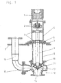
- the prior art corresponding centrifugal pump unit has an electric motor 1, which has a coupling 2 with the aggregate shaft 3 is connected.
- the unit shaft 3 in a lantern 5 rotatably mounted.
- the lantern has 5 a flange 6 connected to a flange 7 of an intermediate tube 8 via a Plurality of screws is releasably connected.
- the flange 7 of the intermediate tube 8 is in turn with the lid 9 of a container, not shown above Screws connected.
- the intermediate tube 8 thus protrudes into the container; it encloses the Aggregate shaft 3.
- the intermediate tube 8 has a Flange 10, which is connected to the housing 11 of a centrifugal pump 12 - also via a Plurality of screws - is detachably connected.
- the centrifugal pump 12 has a Impeller 13, the liquid in the container sucks through an inlet 14 and via an outlet 15 and a pipe 16 in an outside of the Container located, not shown pipeline promotes.
- the intermediate tube 8 is integral with its flanges 7 and 10 in one Casting produced. That means that for every size of use coming intermediate pipes must be maintained own casting model, and that deviates from a predetermined size deviating pipes only can be provided under greatly increased effort.
- FIGs. 2 and 3 overcome the indicated Problem by providing a theoretically unlimited number of possible sizes of Provide intermediate pipes. This is made possible by the fact that the Intermediate tubes are designed only as pure pipes, so on flanges is waived. This results in several advantageous options: Existing Pipe material is readily cut to a desired size; Production and storage are thus simplified. Above all, it is now possible use commercially available tube formats, which is due to the omission of a Separate production of the intermediate tubes a decisive economic Advantage means.
- FIG. 2 In the centrifugal pump assembly of FIG. 2 finds an intermediate tube 17, which by tie rods 18 between the flange 6 of the lantern 5 and the Pump housing 11 is clamped, use. In addition, by the Tie rods 18 a loose flange 19 was added, the attachment of the Aggregates used on a container, not shown. The loose flange 19, the is applied directly to the flange 6, by nuts 20, which is below abut him and above the flange 6, braced.
- the Aggregate instead of attaching the unit with the help of a loose flange, the Aggregate but also be mounted directly on a container lid.
- the type of attachment itself would basically be the same as in FIG. 2 shown.
- FIG. 3 has a comparatively short lantern 21 in which no bearings are provided for the unit shaft 3. Instead, one is Slide bearing 22 on the cover 23 of the pump housing 11 for supporting the shaft. 3 arranged.
- This is a known type of storage.
- a special feature lies in the arrangement of the flange 19:
- sleeves 24 are also different kind of spacers, such as discs or plates, usable. It can also cover the entire flange circumference covering rings or pipes are used. Finally, it is also possible the desired distance through additional nuts, which are above the loose flange 19 and below the lantern 6 are arranged to produce.
- FIGS. 4 and 5 elements of two to tie rods are alternative Fortifications shown.
- Fig. 4 shows nuts 25 which are welded to pins 26.
- the pins 26 are anchored in holes of the intermediate tube 17.
- the necessary screw connection is by - not shown - screws or threaded bolts produced.
- Fig. 5 shows an embodiment in which a - second - loose flange 27 use place.
- the loose flange 27 is supported on a plurality of pins 28, the are distributed uniformly over the circumference of the intermediate tube 17.
- pins 28 can with similar effect a snap ring used in an all around groove of the Swissrohres 17 is arranged.
- a split loose flange, arranged in a groove of the intermediate tube and through the still to be attached Screwed fixed, can be used at this point.
- Fig. 6 shows an alternative of the connection between a lantern 21 and a flat part 29.
- the lantern 21 is different with two hole circles Diameter equipped. This allows its use in different ways large aggregates.
- a connection is included shown a smaller aggregate.
- the flange of the lantern 21 on the one hand via screws 30 with the flat part 29 and on the other hand via tie rods 18th connected to the pump housing 11.
- tie rods 18th connected to the pump housing 11.
- For a larger aggregate would a direct connection between the lantern 21 and the flat part 29th by means of tie rods 18 via the outer circle of holes.
- This kind of Connection would correspond to the type shown in FIG.
- an intermediate bearing 31 is disposed in the intermediate pipe 17 shown.
- the intermediate storage 31 consists essentially of a bearing carrier 32 and attached to this bearing shell 33.
- the shaft 3 in turn carries a cooperating with the bearing shell 33 bearing bush 34.
- the bearing carrier 32 is fastened by means of stud bolts 35 in the intermediate tube 17. Installation and Alignment of the intermediate bearing 31 carried out in such a way that the intermediate storage 31 first preassembled with loose screw in the intermediate tube 17 and only after pushing through the shaft 3 by uniform tightening the Stud screws 35 is fixed.
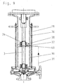
- Fig. 9 shows an embodiment in which two tubes 36 of equal design be joined together a common intermediate pipe. Between the two tubes 36, a bearing support 37 is clamped, which together with the tubes 36 is tensioned by tie rods 18. The held by the bearing carrier 37 Intermediate bearing 38 encloses here also arranged on the shaft 3 socket 34th
- the bearings 31 and 38 of Figs. 7 to 9 each have a bearing lubrication, the via a connected to the pressure side of the pump unit line 39 with Lubricating fluid is supplied.
- the line 39 each opens into a bore 40 in the bearing bracket 32 and 37, respectively.
Landscapes
- Engineering & Computer Science (AREA)
- Mechanical Engineering (AREA)
- General Engineering & Computer Science (AREA)
- Structures Of Non-Positive Displacement Pumps (AREA)
Abstract
Description
- Fig. 1
- ein dem Stand der Technik entsprechendes Kreiselpumpenaggregat mit einer freitragenden, allein in einer Laterne gelagerten Aggregatwelle;
- Fig. 2
- ein Kreiselpumpenaggregat gemäß der Erfindung, dessen Welle ebenfalls freitragend ausgebildet ist;
- Fig. 3
- ein Pumpenaggregat, das eine Variante der Erfindung zeigt, wobei dessen Welle noch im Gehäuse der Pumpe gelagert ist;
- Fig. 4 bis 6
- Einzelheiten alternativer Formen der Befestigung des Aggregates;
- Fig. 7 und 8
- zwei Ansichten eines Zwischenlagers für die Welle eines erfindungsgemäßen Kreiselpumpenaggregates;
- Fig. 9
- ein der Erfindung entsprechendes Kreiselpumpenaggregat mit einer weiteren möglichen Gestaltung des Zwischenlagers.
Claims (24)
- Vertikales Kreiselpumpenaggregat, insbesondere für den nassen Einbau in einen geschlossenen Behälter, mit einem zwischen einer den Elektromotor (1) des Aggregates tragenden Laterne (5; 21) und dem Gehäuse (11) der Kreiselpumpe (12) angeordneten, die Welle (3) des Aggregates umschließenden Zwischenrohr (17), wobei die Befestigung des Aggregates an einem horizontal verlaufenden, unterhalb des Flansches (6) der Laterne (5; 21) angeordneten flachen Teil (19; 29), insbesondere am Deckel eines Behälters erfolgt, dadurch gekennzeichnet, daß das Zwischenrohr (17) ohne Flansche oder sonstige Verbreiterungen an seinen Stirnflächen ausgeführt ist und die Stirnflächen durch gleichmäßig über den Umfang verteilte Schraubverbindungen (18, 20; 25; 27) gegen die Laterne (5; 21) und das Pumpengehäuse (11) gedrückt werden, wobei die Laterne (5; 21) und das darunter angeordnete flache Teil (19; 29) über Schraubverbindungen (18, 20; 25; 27; 30) miteinander verbunden sind.
- Kreiselpumpenaggregat nach Anspruch 1, dadurch gekennzeichnet, daß die Laterne (5; 21) mit zwei auf unterschiedlichen Durchmessern angeordneten Lochkreisen ausgestattet ist.
- Kreiselpumpenaggregat nach Anspruch 2, dadurch gekennzeichnet, daß die Schraubverbindungen (30) zwischen dem flachen Teil (29) und der Laterne (5; 21) über den Lochkreis kleineren Durchmessers erfolgt, wobei zusätzlich Schrauben (30) zu der auf dem Lochkreis größeren Durchmessers erfolgenden Verbindung des flachen Teils (19; 29) mit der Laterne (5; 21) vorgesehen sind.
- Kreiselpumpenaggregat nach Anspruch 2, dadurch gekennzeichnet, daß die Schraubverbindungen (18, 20; 25; 27) zwischen dem flachen Teil (29) und der Laterne (5; 21) über den Lochkreis größeren Durchmessers erfolgt, wobei die Schraubverbindungen (18, 20; 25; 27) gleichzeitig das unter der Laterne (5; 21) angeordnete flache Teil (19) aufnehmen.
- Kreiselpumpenaggregat nach einem der Ansprüche 1 bis 4, dadurch gekennzeichnet, daß das unter der Laterne (5; 21) angeordnete flache Teil (19; 29) ein Losflansch ist.
- Kreiselpumpenaggregat nach einem der Ansprüche 1 bis 5, dadurch gekennzeichnet, daß das Zwischenrohr (17) mittels Zugankern (18) eingespannt ist, wobei die Zuganker (18) einerseits an der Laterne (5; 21) und andererseits an dem Pumpengehäuse (11) mittels Schraubverbindung befestigt sind.
- Kreiselpumpenaggregat nach Anspruch 6, dadurch gekennzeichnet, daß die Zuganker (18) gleichzeitig das unter der Laterne (5; 21) angeordnete flache Teil (19; 29) mit Hilfe von Muttern (20) aufnehmen.
- Kreiselpumpenaggregat nach einem der vorhergehenden Ansprüche, dadurch gekennzeichnet, daß das Zwischenrohr (17) mit über den gesamten Umfang verlaufenden Nuten versehen ist, in die jeweils ein mit Teilungsfugen versehener Losflansch mit Hilfe von einem oder mehreren an seinem Innenumfang angeordneten Vorsprüngen eingreift, wobei dieser Losflansch über Schraubverbindungen mit dem flachen Teil (19; 29) verbunden ist.
- Kreiselpumpenaggregat nach einem der vorhergehenden Ansprüche, dadurch gekennzeichnet, daß das Zwischenrohr (17) mit Ausnehmungen versehen ist, in welche Halterungselemente (28) formschlüssig eingreifen, wobei die Halterungselemente (28) jeweils einen mit Bohrungen zur Aufnahme von Schraubverbindungen versehenen Losflansch (27) abstützen.
- Kreiselpumpenaggregat nach einem der vorhergehenden Ansprüche, dadurch gekennzeichnet, daß das Zwischenrohr (17) mit über den gesamten Umfang verlaufenden Nuten versehen ist, die jeweils einen Stützring aufnehmen, an dem der Losflansch (27) zur Anlage kommt.
- Kreiselpumpenaggregat nach Anspruch 9, dadurch gekennzeichnet, daß das Zwischenrohr (17) mit gleichmäßig über den Umfang verteilten Löchern versehen ist, die der Aufnahme von Stiften (28) dienen, welche jeweils den Losflansch (27) abstützen.
- Kreiselpumpenaggregat nach Anspruch 9, dadurch gekennzeichnet, daß das Zwischenrohr (17) mit gleichmäßig über den Umfang verteilten Löchern versehen ist, die der Aufnahme von Stiften (26) dienen, wobei jeder dieser Stifte (26) eine Buchse (25) zur Aufnahme einer Schraubverbindung trägt.
- Kreiselpumpenaggregat nach einem der vorhergehenden Ansprüche, dadurch gekennzeichnet, daß die Stirnflächen des Zwischenrohres (17) am Flansch (6) der Laterne (5; 21) und am Pumpengehäuse (11), insbesondere an dessen druckseitigern Deckel anliegen.
- Kreiselpumpenaggregat nach einem der vorhergehenden Ansprüche, dadurch gekennzeichnet, daß eine oder beide Stirnflächen des Zwischenrohres (17) an einem weiteren Losflansch anliegen.
- Kreiselpumpenaggregat nach einem der vorhergehenden Ansprüche, dadurch gekennzeichnet, daß das Zwischenrohr (17) durch handelsübliches Rohrmaterial gebildet wird, welches gegebenenfalls durch Kürzen an die jeweiligen Verhältnisse angepaßt wird.
- Kreiselpumpenaggregat nach einem der vorhergehenden Ansprüche, dadurch gekennzeichnet, daß zwischen dem flachen Teil (19; 29) und der Laterne (5; 21) Abstandshalter (24) angeordnet sind.
- Kreiselpumpenaggregat nach Anspruch 16, dadurch gekennzeichnet, daß die Abstandshalter durch Hülsen (24) gebildet werden.
- Kreiselpumpenaggregat nach Anspruch 16, dadurch gekennzeichnet, daß der Abstand durch Muttern (20) hergestellt wird, die oberhalb des flachen Teils (19; 29) und unterhalb der Laterne (5; 21) angeordnet sind.
- Kreiselpumpenaggregat nach einem der vorhergehenden Ansprüche, gekennzeichnet durch ein mit einem Zwischenlager (31) für die Welle (3) ausgestattetes Zwischenrohr (17).
- Kreiselpumpenaggregat nach Anspruch 19, dadurch gekennzeichnet, daß das Zwischenlager (31) mittels mehreren das Zwischenrohr (17) durchdringenden Schrauben (35) befestigt ist.
- Kreiselpumpenaggregat nach Anspruch 20, dadurch gekennzeichnet, daß drei gleichmäßig über den Umfang verteilte, mittels Muttern und Kontermuttern zu arretierende, jeweils mit Hilfe eines im Zwischenrohr (17) angeordneten Gewindes einstellbare Schrauben (35) Verwendung finden.
- Kreiselpumpenaggregat nach Anspruch 19, gekennzeichnet durch ein in zwei gleichartige Hälften (36) unterteiltes Zwischenrohr, wobei zwischen den beiden Hälften (36) ein in seiner Kontur den Stirnflächen der Hälften (36) angepaßter Träger (37) für ein Zwischenlager (38) eingeklemmt ist.
- Kreiselpumpenaggregat nach einem der Ansprüche 19 bis 22, dadurch gekennzeichnet, daß das Zwischenlager (31; 38) über eine Leitung (39) mit Schmierflüssigkeit versorgt wird.
- Kreiselpumpenaggregat nach Anspruch 23, dadurch gekennzeichnet, daß die Leitung (39) mit dem druckseitigen Innenbereich des Kreiselpumpenaggregates verbunden ist.
Priority Applications (1)
| Application Number | Priority Date | Filing Date | Title |
|---|---|---|---|
| PL05001887T PL1564410T3 (pl) | 2004-02-13 | 2005-01-29 | Pionowy zespół pompy odśrodkowej |
Applications Claiming Priority (4)
| Application Number | Priority Date | Filing Date | Title |
|---|---|---|---|
| DE102004007090 | 2004-02-13 | ||
| DE102004007090 | 2004-02-13 | ||
| DE102004029557 | 2004-06-18 | ||
| DE102004029557A DE102004029557B4 (de) | 2004-02-13 | 2004-06-18 | Vertikales Kreiselpumpenaggregat |
Publications (3)
| Publication Number | Publication Date |
|---|---|
| EP1564410A2 true EP1564410A2 (de) | 2005-08-17 |
| EP1564410A3 EP1564410A3 (de) | 2009-07-01 |
| EP1564410B1 EP1564410B1 (de) | 2016-11-16 |
Family
ID=34702136
Family Applications (1)
| Application Number | Title | Priority Date | Filing Date |
|---|---|---|---|
| EP05001887.8A Expired - Lifetime EP1564410B1 (de) | 2004-02-13 | 2005-01-29 | Vertikales Kreiselpumpenaggregat |
Country Status (2)
| Country | Link |
|---|---|
| US (1) | US7828531B2 (de) |
| EP (1) | EP1564410B1 (de) |
Cited By (2)
| Publication number | Priority date | Publication date | Assignee | Title |
|---|---|---|---|---|
| CN107939737A (zh) * | 2017-12-25 | 2018-04-20 | 杭州福斯达深冷装备股份有限公司 | 一种导向支架及立式高压离心泵泵体的导向结构 |
| CN114294268A (zh) * | 2021-12-28 | 2022-04-08 | 威乐(中国)水泵系统有限公司 | 一种立式离心泵 |
Families Citing this family (11)
| Publication number | Priority date | Publication date | Assignee | Title |
|---|---|---|---|---|
| US8079622B2 (en) * | 2006-09-25 | 2011-12-20 | Dresser-Rand Company | Axially moveable spool connector |
| MX2011002665A (es) | 2008-09-10 | 2011-07-28 | Pentair Pump Group Inc | Bomba centrifuga de multiples etapas, de alta eficiencia y metodo para ensamblado. |
| US20110189036A1 (en) * | 2010-01-29 | 2011-08-04 | O'Drill/MCM Inc. | Modular Vertical Pump Assembly |
| US8435016B2 (en) | 2010-11-10 | 2013-05-07 | Hamilton Sundstrand Corporation | Vertical shaft pumping system with lubricant impeller arrangement |
| US9435344B1 (en) | 2012-09-12 | 2016-09-06 | Sidney T. Highnote | Liquid sealed pump |
| EP2759710A1 (de) * | 2013-01-23 | 2014-07-30 | Sulzer Pumpen AG | Zentrifugalpumpe und Hülse zum Kuppeln der Welle einer Zentrifugalpumpe mit der Welle eines Antriebsmotors |
| PL3242034T3 (pl) | 2013-03-19 | 2019-10-31 | Flow Control LLC | Pompa o niskim profilu z możliwością montażu w różnych konfiguracjach |
| USD701246S1 (en) | 2013-07-01 | 2014-03-18 | Flow Control Llc. | Low profile pump |
| CN104329231A (zh) * | 2014-09-22 | 2015-02-04 | 安徽富乐泰水泵系统有限公司 | 小型水泵的机体连接装置 |
| KR101715604B1 (ko) * | 2016-06-03 | 2017-03-13 | (유)한성산기 | 진동 저감형 펌프 |
| CA3061943A1 (en) * | 2018-11-21 | 2020-05-21 | Sulzer Management Ag | Multiphase pump |
Citations (4)
| Publication number | Priority date | Publication date | Assignee | Title |
|---|---|---|---|---|
| DE1528888A1 (de) | 1965-04-01 | 1969-10-09 | Wernert & Co Kg H | Einhaengepumpe fuer angreifende Medien |
| DE2053147A1 (de) | 1970-10-19 | 1972-04-20 | Victaulic Co Of America | Verbindung zwischen Rohren und Flanschen und Verfahren zu ihrer Herstellung |
| US3861722A (en) | 1973-07-31 | 1975-01-21 | Coupco Ltd | Flange adaptor |
| US6315530B1 (en) | 1999-10-05 | 2001-11-13 | Buffalo Pumps, Inc. | Submerged pump having a shaft isolator |
Family Cites Families (7)
| Publication number | Priority date | Publication date | Assignee | Title |
|---|---|---|---|---|
| US2890659A (en) * | 1955-05-27 | 1959-06-16 | Haentjens Otto | Slurry pump |
| US3199745A (en) * | 1963-02-15 | 1965-08-10 | Graymills Corp | Portable pump assembly |
| US3776660A (en) * | 1972-02-22 | 1973-12-04 | Nl Industries Inc | Pump for molten salts and metals |
| DE4128673C1 (de) * | 1991-08-29 | 1992-08-06 | Ksb Aktiengesellschaft, 6710 Frankenthal, De | |
| FR2717535A1 (fr) * | 1994-03-17 | 1995-09-22 | Siebec Sa | Pompe verticale. |
| US5716195A (en) * | 1995-02-08 | 1998-02-10 | Thut; Bruno H. | Pumps for pumping molten metal |
| US5951248A (en) * | 1997-08-08 | 1999-09-14 | Baker Hughes Incorporated | Vertical configured pump |
-
2005
- 2005-01-29 EP EP05001887.8A patent/EP1564410B1/de not_active Expired - Lifetime
- 2005-02-14 US US11/056,168 patent/US7828531B2/en active Active
Patent Citations (4)
| Publication number | Priority date | Publication date | Assignee | Title |
|---|---|---|---|---|
| DE1528888A1 (de) | 1965-04-01 | 1969-10-09 | Wernert & Co Kg H | Einhaengepumpe fuer angreifende Medien |
| DE2053147A1 (de) | 1970-10-19 | 1972-04-20 | Victaulic Co Of America | Verbindung zwischen Rohren und Flanschen und Verfahren zu ihrer Herstellung |
| US3861722A (en) | 1973-07-31 | 1975-01-21 | Coupco Ltd | Flange adaptor |
| US6315530B1 (en) | 1999-10-05 | 2001-11-13 | Buffalo Pumps, Inc. | Submerged pump having a shaft isolator |
Cited By (2)
| Publication number | Priority date | Publication date | Assignee | Title |
|---|---|---|---|---|
| CN107939737A (zh) * | 2017-12-25 | 2018-04-20 | 杭州福斯达深冷装备股份有限公司 | 一种导向支架及立式高压离心泵泵体的导向结构 |
| CN114294268A (zh) * | 2021-12-28 | 2022-04-08 | 威乐(中国)水泵系统有限公司 | 一种立式离心泵 |
Also Published As
| Publication number | Publication date |
|---|---|
| US7828531B2 (en) | 2010-11-09 |
| US20050191192A1 (en) | 2005-09-01 |
| EP1564410B1 (de) | 2016-11-16 |
| EP1564410A3 (de) | 2009-07-01 |
Similar Documents
| Publication | Publication Date | Title |
|---|---|---|
| EP1564410B1 (de) | Vertikales Kreiselpumpenaggregat | |
| EP3099899B1 (de) | Schraubenspindelpumpe | |
| DE202007004103U1 (de) | Schmierritzel und Schmiereinrichtung | |
| DE2904384A1 (de) | Gehaeuse fuer sich im wesentlichen axial erstreckende rotierende maschinen, insbesondere elektromotoren und mehrstufige pumpen | |
| DE202015104783U1 (de) | Fahrradrahmen mit einer Aufnahmevorrichtung für ein Antriebsgehäuse | |
| EP0935073A1 (de) | Elastomerstator für Exzenterschneckenpumpen | |
| DE69009859T2 (de) | Vorrichtung zur Herstellung verstärkter Polymerrohre. | |
| DE102004029557B4 (de) | Vertikales Kreiselpumpenaggregat | |
| DE102004059515B3 (de) | Vorrichtung zur Unterstützung von extrudierten Kunststoffprofilen, insbesondere Rohren, in einer Extrusionslinie | |
| DE2340499B1 (de) | Mehrteilige Schnecke für eine Schnekkenstrangpresse zur Verarbeitung von Kunststoffen | |
| EP1666671A1 (de) | Schlitzwandfräse | |
| EP2358931B1 (de) | Oberwalze für ein streckwerk | |
| WO2009115142A1 (de) | Handwerkzeugmaschine, insbesondere handgeführte schleifmaschine | |
| EP3439847B1 (de) | Innentemperierbare schnecke, anlage sowie verfahren unter verwendung einer derartigen schnecke | |
| CH658802A5 (en) | Agitator mill | |
| DE3442977C2 (de) | ||
| DE202011004414U1 (de) | Entwässer- und Aufbereitungsmaschine | |
| DE3635620C2 (de) | ||
| CH712345B1 (de) | Vorrichtung mit einer Halteeinrichtung für die Positionierung einer Schraubenmutter einer Schraubenverbindung bei Überkopfmontage. | |
| DE102005043868B4 (de) | Extrudergestell | |
| DE102004040720B4 (de) | Exzenterschneckenpumpe | |
| DE202005005872U1 (de) | Stützhülse für Zylinderkopfschrauben und Zylinderkopf | |
| WO2010105682A1 (de) | Anordnung mit zahnradpumpe mit geteiltem pumpengehäuse | |
| DE102010010894B4 (de) | Stützeinrichtung für Werkstücke, wie Rohre und dergleichen, sowie Trennvorrichtung für solche Werkstücke | |
| WO2009039881A1 (de) | Zahnradpumpe mit geteiltem pumpengehäuse |
Legal Events
| Date | Code | Title | Description |
|---|---|---|---|
| PUAI | Public reference made under article 153(3) epc to a published international application that has entered the european phase |
Free format text: ORIGINAL CODE: 0009012 |
|
| AK | Designated contracting states |
Kind code of ref document: A2 Designated state(s): AT BE BG CH CY CZ DE DK EE ES FI FR GB GR HU IE IS IT LI LT LU MC NL PL PT RO SE SI SK TR |
|
| AX | Request for extension of the european patent |
Extension state: AL BA HR LV MK YU |
|
| PUAL | Search report despatched |
Free format text: ORIGINAL CODE: 0009013 |
|
| AK | Designated contracting states |
Kind code of ref document: A3 Designated state(s): AT BE BG CH CY CZ DE DK EE ES FI FR GB GR HU IE IS IT LI LT LU MC NL PL PT RO SE SI SK TR |
|
| AX | Request for extension of the european patent |
Extension state: AL BA HR LV MK YU |
|
| 17P | Request for examination filed |
Effective date: 20091216 |
|
| AKX | Designation fees paid |
Designated state(s): AT BE BG CH CY CZ DE DK EE ES FI FR GB GR HU IE IS IT LI LT LU MC NL PL PT RO SE SI SK TR |
|
| 17Q | First examination report despatched |
Effective date: 20120326 |
|
| GRAP | Despatch of communication of intention to grant a patent |
Free format text: ORIGINAL CODE: EPIDOSNIGR1 |
|
| INTG | Intention to grant announced |
Effective date: 20160617 |
|
| GRAS | Grant fee paid |
Free format text: ORIGINAL CODE: EPIDOSNIGR3 |
|
| GRAA | (expected) grant |
Free format text: ORIGINAL CODE: 0009210 |
|
| AK | Designated contracting states |
Kind code of ref document: B1 Designated state(s): AT BE BG CH CY CZ DE DK EE ES FI FR GB GR HU IE IS IT LI LT LU MC NL PL PT RO SE SI SK TR |
|
| REG | Reference to a national code |
Ref country code: GB Ref legal event code: FG4D Free format text: NOT ENGLISH Ref country code: DE Ref legal event code: R081 Ref document number: 502005015421 Country of ref document: DE Owner name: KSB SE & CO. KGAA, DE Free format text: FORMER OWNER: KSB AG, 67227 FRANKENTHAL, DE |
|
| REG | Reference to a national code |
Ref country code: CH Ref legal event code: EP |
|
| REG | Reference to a national code |
Ref country code: IE Ref legal event code: FG4D Free format text: LANGUAGE OF EP DOCUMENT: GERMAN |
|
| REG | Reference to a national code |
Ref country code: AT Ref legal event code: REF Ref document number: 846226 Country of ref document: AT Kind code of ref document: T Effective date: 20161215 |
|
| REG | Reference to a national code |
Ref country code: DE Ref legal event code: R096 Ref document number: 502005015421 Country of ref document: DE |
|
| REG | Reference to a national code |
Ref country code: FR Ref legal event code: PLFP Year of fee payment: 13 |
|
| REG | Reference to a national code |
Ref country code: DK Ref legal event code: T3 Effective date: 20170130 |
|
| REG | Reference to a national code |
Ref country code: PT Ref legal event code: SC4A Ref document number: 1564410 Country of ref document: PT Date of ref document: 20170210 Kind code of ref document: T Free format text: AVAILABILITY OF NATIONAL TRANSLATION Effective date: 20170131 |
|
| REG | Reference to a national code |
Ref country code: RO Ref legal event code: EPE |
|
| REG | Reference to a national code |
Ref country code: SE Ref legal event code: TRGR |
|
| REG | Reference to a national code |
Ref country code: NL Ref legal event code: FP |
|
| REG | Reference to a national code |
Ref country code: LT Ref legal event code: MG4D |
|
| REG | Reference to a national code |
Ref country code: ES Ref legal event code: FG2A Ref document number: 2609916 Country of ref document: ES Kind code of ref document: T3 Effective date: 20170425 |
|
| PG25 | Lapsed in a contracting state [announced via postgrant information from national office to epo] |
Ref country code: GR Free format text: LAPSE BECAUSE OF FAILURE TO SUBMIT A TRANSLATION OF THE DESCRIPTION OR TO PAY THE FEE WITHIN THE PRESCRIBED TIME-LIMIT Effective date: 20170217 Ref country code: LT Free format text: LAPSE BECAUSE OF FAILURE TO SUBMIT A TRANSLATION OF THE DESCRIPTION OR TO PAY THE FEE WITHIN THE PRESCRIBED TIME-LIMIT Effective date: 20161116 |
|
| PG25 | Lapsed in a contracting state [announced via postgrant information from national office to epo] |
Ref country code: SK Free format text: LAPSE BECAUSE OF FAILURE TO SUBMIT A TRANSLATION OF THE DESCRIPTION OR TO PAY THE FEE WITHIN THE PRESCRIBED TIME-LIMIT Effective date: 20161116 Ref country code: EE Free format text: LAPSE BECAUSE OF FAILURE TO SUBMIT A TRANSLATION OF THE DESCRIPTION OR TO PAY THE FEE WITHIN THE PRESCRIBED TIME-LIMIT Effective date: 20161116 |
|
| REG | Reference to a national code |
Ref country code: DE Ref legal event code: R097 Ref document number: 502005015421 Country of ref document: DE |
|
| PG25 | Lapsed in a contracting state [announced via postgrant information from national office to epo] |
Ref country code: BG Free format text: LAPSE BECAUSE OF FAILURE TO SUBMIT A TRANSLATION OF THE DESCRIPTION OR TO PAY THE FEE WITHIN THE PRESCRIBED TIME-LIMIT Effective date: 20170216 |
|
| PLBE | No opposition filed within time limit |
Free format text: ORIGINAL CODE: 0009261 |
|
| STAA | Information on the status of an ep patent application or granted ep patent |
Free format text: STATUS: NO OPPOSITION FILED WITHIN TIME LIMIT |
|
| PG25 | Lapsed in a contracting state [announced via postgrant information from national office to epo] |
Ref country code: MC Free format text: LAPSE BECAUSE OF FAILURE TO SUBMIT A TRANSLATION OF THE DESCRIPTION OR TO PAY THE FEE WITHIN THE PRESCRIBED TIME-LIMIT Effective date: 20161116 |
|
| 26N | No opposition filed |
Effective date: 20170817 |
|
| REG | Reference to a national code |
Ref country code: IE Ref legal event code: MM4A |
|
| REG | Reference to a national code |
Ref country code: HU Ref legal event code: AG4A Ref document number: E032905 Country of ref document: HU |
|
| PG25 | Lapsed in a contracting state [announced via postgrant information from national office to epo] |
Ref country code: SI Free format text: LAPSE BECAUSE OF FAILURE TO SUBMIT A TRANSLATION OF THE DESCRIPTION OR TO PAY THE FEE WITHIN THE PRESCRIBED TIME-LIMIT Effective date: 20161116 |
|
| REG | Reference to a national code |
Ref country code: FR Ref legal event code: PLFP Year of fee payment: 14 |
|
| REG | Reference to a national code |
Ref country code: DE Ref legal event code: R081 Ref document number: 502005015421 Country of ref document: DE Owner name: KSB SE & CO. KGAA, DE Free format text: FORMER OWNER: KSB AKTIENGESELLSCHAFT, 67227 FRANKENTHAL, DE |
|
| PGFP | Annual fee paid to national office [announced via postgrant information from national office to epo] |
Ref country code: CZ Payment date: 20171227 Year of fee payment: 14 |
|
| PG25 | Lapsed in a contracting state [announced via postgrant information from national office to epo] |
Ref country code: IE Free format text: LAPSE BECAUSE OF NON-PAYMENT OF DUE FEES Effective date: 20170129 |
|
| PGFP | Annual fee paid to national office [announced via postgrant information from national office to epo] |
Ref country code: PL Payment date: 20171227 Year of fee payment: 14 Ref country code: PT Payment date: 20171222 Year of fee payment: 14 Ref country code: LU Payment date: 20171221 Year of fee payment: 14 |
|
| PGFP | Annual fee paid to national office [announced via postgrant information from national office to epo] |
Ref country code: NL Payment date: 20180121 Year of fee payment: 14 |
|
| PGFP | Annual fee paid to national office [announced via postgrant information from national office to epo] |
Ref country code: FI Payment date: 20180123 Year of fee payment: 14 Ref country code: RO Payment date: 20180109 Year of fee payment: 14 |
|
| PGFP | Annual fee paid to national office [announced via postgrant information from national office to epo] |
Ref country code: SE Payment date: 20180124 Year of fee payment: 14 Ref country code: BE Payment date: 20171221 Year of fee payment: 14 Ref country code: IT Payment date: 20180131 Year of fee payment: 14 Ref country code: AT Payment date: 20180123 Year of fee payment: 14 |
|
| REG | Reference to a national code |
Ref country code: NL Ref legal event code: MM Effective date: 20190201 |
|
| REG | Reference to a national code |
Ref country code: AT Ref legal event code: MM01 Ref document number: 846226 Country of ref document: AT Kind code of ref document: T Effective date: 20190129 |
|
| PG25 | Lapsed in a contracting state [announced via postgrant information from national office to epo] |
Ref country code: LU Free format text: LAPSE BECAUSE OF NON-PAYMENT OF DUE FEES Effective date: 20190129 |
|
| REG | Reference to a national code |
Ref country code: BE Ref legal event code: MM Effective date: 20190131 |
|
| PG25 | Lapsed in a contracting state [announced via postgrant information from national office to epo] |
Ref country code: PT Free format text: LAPSE BECAUSE OF NON-PAYMENT OF DUE FEES Effective date: 20190729 Ref country code: RO Free format text: LAPSE BECAUSE OF NON-PAYMENT OF DUE FEES Effective date: 20190129 Ref country code: CY Free format text: LAPSE BECAUSE OF NON-PAYMENT OF DUE FEES Effective date: 20161116 Ref country code: FI Free format text: LAPSE BECAUSE OF NON-PAYMENT OF DUE FEES Effective date: 20190129 Ref country code: SE Free format text: LAPSE BECAUSE OF NON-PAYMENT OF DUE FEES Effective date: 20190130 Ref country code: NL Free format text: LAPSE BECAUSE OF NON-PAYMENT OF DUE FEES Effective date: 20190201 Ref country code: CZ Free format text: LAPSE BECAUSE OF NON-PAYMENT OF DUE FEES Effective date: 20190129 |
|
| PG25 | Lapsed in a contracting state [announced via postgrant information from national office to epo] |
Ref country code: BE Free format text: LAPSE BECAUSE OF NON-PAYMENT OF DUE FEES Effective date: 20190131 |
|
| PG25 | Lapsed in a contracting state [announced via postgrant information from national office to epo] |
Ref country code: AT Free format text: LAPSE BECAUSE OF NON-PAYMENT OF DUE FEES Effective date: 20190129 |
|
| PG25 | Lapsed in a contracting state [announced via postgrant information from national office to epo] |
Ref country code: IT Free format text: LAPSE BECAUSE OF NON-PAYMENT OF DUE FEES Effective date: 20190129 |
|
| PG25 | Lapsed in a contracting state [announced via postgrant information from national office to epo] |
Ref country code: IS Free format text: LAPSE BECAUSE OF FAILURE TO SUBMIT A TRANSLATION OF THE DESCRIPTION OR TO PAY THE FEE WITHIN THE PRESCRIBED TIME-LIMIT Effective date: 20170316 |
|
| PG25 | Lapsed in a contracting state [announced via postgrant information from national office to epo] |
Ref country code: PL Free format text: LAPSE BECAUSE OF NON-PAYMENT OF DUE FEES Effective date: 20190129 |
|
| P01 | Opt-out of the competence of the unified patent court (upc) registered |
Effective date: 20230712 |
|
| PGFP | Annual fee paid to national office [announced via postgrant information from national office to epo] |
Ref country code: ES Payment date: 20240201 Year of fee payment: 20 |
|
| PGFP | Annual fee paid to national office [announced via postgrant information from national office to epo] |
Ref country code: HU Payment date: 20240111 Year of fee payment: 20 Ref country code: DE Payment date: 20240201 Year of fee payment: 20 Ref country code: GB Payment date: 20240124 Year of fee payment: 20 Ref country code: CH Payment date: 20240202 Year of fee payment: 20 |
|
| PGFP | Annual fee paid to national office [announced via postgrant information from national office to epo] |
Ref country code: TR Payment date: 20240125 Year of fee payment: 20 Ref country code: FR Payment date: 20240126 Year of fee payment: 20 Ref country code: DK Payment date: 20240124 Year of fee payment: 20 |
|
| REG | Reference to a national code |
Ref country code: DE Ref legal event code: R071 Ref document number: 502005015421 Country of ref document: DE |
|
| REG | Reference to a national code |
Ref country code: CH Ref legal event code: PL |
|
| REG | Reference to a national code |
Ref country code: DK Ref legal event code: EUP Expiry date: 20250129 |
|
| REG | Reference to a national code |
Ref country code: ES Ref legal event code: FD2A Effective date: 20250205 |
|
| REG | Reference to a national code |
Ref country code: GB Ref legal event code: PE20 Expiry date: 20250128 |
|
| PG25 | Lapsed in a contracting state [announced via postgrant information from national office to epo] |
Ref country code: ES Free format text: LAPSE BECAUSE OF EXPIRATION OF PROTECTION Effective date: 20250130 |
|
| PG25 | Lapsed in a contracting state [announced via postgrant information from national office to epo] |
Ref country code: GB Free format text: LAPSE BECAUSE OF EXPIRATION OF PROTECTION Effective date: 20250128 |