EP1561578A1 - Verfahren zum Transportieren von Feuchtmittel von einer ersten Walze an die Oberfläche eines Formzylinders einer Druckmaschine - Google Patents
Verfahren zum Transportieren von Feuchtmittel von einer ersten Walze an die Oberfläche eines Formzylinders einer Druckmaschine Download PDFInfo
- Publication number
- EP1561578A1 EP1561578A1 EP05100699A EP05100699A EP1561578A1 EP 1561578 A1 EP1561578 A1 EP 1561578A1 EP 05100699 A EP05100699 A EP 05100699A EP 05100699 A EP05100699 A EP 05100699A EP 1561578 A1 EP1561578 A1 EP 1561578A1
- Authority
- EP
- European Patent Office
- Prior art keywords
- roller
- forme cylinder
- surface speed
- speed
- drive
- Prior art date
- Legal status (The legal status is an assumption and is not a legal conclusion. Google has not performed a legal analysis and makes no representation as to the accuracy of the status listed.)
- Granted
Links
- 238000000034 method Methods 0.000 title claims abstract description 66
- 238000007639 printing Methods 0.000 title claims description 51
- XLYOFNOQVPJJNP-UHFFFAOYSA-N water Substances O XLYOFNOQVPJJNP-UHFFFAOYSA-N 0.000 title description 3
- 238000013016 damping Methods 0.000 title 1
- 230000005540 biological transmission Effects 0.000 claims description 6
- 239000000463 material Substances 0.000 claims description 6
- 229920001971 elastomer Polymers 0.000 claims description 5
- VYZAMTAEIAYCRO-UHFFFAOYSA-N Chromium Chemical compound [Cr] VYZAMTAEIAYCRO-UHFFFAOYSA-N 0.000 claims description 4
- 239000000919 ceramic Substances 0.000 claims description 4
- 229910001220 stainless steel Inorganic materials 0.000 claims description 4
- 239000010935 stainless steel Substances 0.000 claims description 4
- 239000003795 chemical substances by application Substances 0.000 claims description 3
- 239000000806 elastomer Substances 0.000 claims description 3
- 239000004959 Rilsan Substances 0.000 claims description 2
- 239000004033 plastic Substances 0.000 claims description 2
- 229920003023 plastic Polymers 0.000 claims description 2
- 229910052804 chromium Inorganic materials 0.000 claims 2
- 239000011651 chromium Substances 0.000 claims 2
- 230000008569 process Effects 0.000 abstract description 11
- 239000000976 ink Substances 0.000 description 27
- 238000007645 offset printing Methods 0.000 description 5
- 230000033228 biological regulation Effects 0.000 description 3
- 230000005660 hydrophilic surface Effects 0.000 description 3
- 239000004918 carbon fiber reinforced polymer Substances 0.000 description 2
- 238000000576 coating method Methods 0.000 description 2
- 238000001816 cooling Methods 0.000 description 2
- 239000013536 elastomeric material Substances 0.000 description 2
- 230000007246 mechanism Effects 0.000 description 2
- 239000002480 mineral oil Substances 0.000 description 2
- 230000002093 peripheral effect Effects 0.000 description 2
- 230000009467 reduction Effects 0.000 description 2
- 238000005096 rolling process Methods 0.000 description 2
- 239000005060 rubber Substances 0.000 description 2
- 239000007921 spray Substances 0.000 description 2
- 238000005507 spraying Methods 0.000 description 2
- 238000011144 upstream manufacturing Methods 0.000 description 2
- LFQSCWFLJHTTHZ-UHFFFAOYSA-N Ethanol Chemical compound CCO LFQSCWFLJHTTHZ-UHFFFAOYSA-N 0.000 description 1
- 239000004952 Polyamide Substances 0.000 description 1
- 210000001015 abdomen Anatomy 0.000 description 1
- 230000009471 action Effects 0.000 description 1
- 230000006978 adaptation Effects 0.000 description 1
- 230000015572 biosynthetic process Effects 0.000 description 1
- 238000009835 boiling Methods 0.000 description 1
- 229910052799 carbon Inorganic materials 0.000 description 1
- 238000003776 cleavage reaction Methods 0.000 description 1
- 239000011248 coating agent Substances 0.000 description 1
- 230000001276 controlling effect Effects 0.000 description 1
- 230000008878 coupling Effects 0.000 description 1
- 238000010168 coupling process Methods 0.000 description 1
- 238000005859 coupling reaction Methods 0.000 description 1
- 230000007423 decrease Effects 0.000 description 1
- 230000001419 dependent effect Effects 0.000 description 1
- 238000010586 diagram Methods 0.000 description 1
- 230000001804 emulsifying effect Effects 0.000 description 1
- 239000000839 emulsion Substances 0.000 description 1
- 230000002708 enhancing effect Effects 0.000 description 1
- 239000000835 fiber Substances 0.000 description 1
- 239000007788 liquid Substances 0.000 description 1
- 239000007769 metal material Substances 0.000 description 1
- 239000003973 paint Substances 0.000 description 1
- 239000002245 particle Substances 0.000 description 1
- 239000000049 pigment Substances 0.000 description 1
- 229920002647 polyamide Polymers 0.000 description 1
- 238000003825 pressing Methods 0.000 description 1
- 238000010992 reflux Methods 0.000 description 1
- 230000001105 regulatory effect Effects 0.000 description 1
- 230000007017 scission Effects 0.000 description 1
- 238000000926 separation method Methods 0.000 description 1
- 230000000087 stabilizing effect Effects 0.000 description 1
- 239000000758 substrate Substances 0.000 description 1
- 230000003319 supportive effect Effects 0.000 description 1
- 239000002352 surface water Substances 0.000 description 1
- 230000002459 sustained effect Effects 0.000 description 1
- 238000005496 tempering Methods 0.000 description 1
- 239000002699 waste material Substances 0.000 description 1
Images

Classifications
-
- B—PERFORMING OPERATIONS; TRANSPORTING
- B41—PRINTING; LINING MACHINES; TYPEWRITERS; STAMPS
- B41F—PRINTING MACHINES OR PRESSES
- B41F7/00—Rotary lithographic machines
- B41F7/20—Details
- B41F7/24—Damping devices
- B41F7/26—Damping devices using transfer rollers
Definitions
- the invention relates to a method for transporting dampening solution from a first Roller to the surface of a forme cylinder of a printing press according to the Preamble of claim 1.
- DE 22 21 423 A1 discloses a device for moistening a printing plate Offset printing machine known in which the wet liquid of an elastic Ink application roller via a transfer roller in contact with the inking roller is fed, wherein the transfer roller outside the flow of the plate cylinder supplied ink lies and form-fitting with cylinder peripheral speed is driven and wherein the transfer roller with a variable speed driven feed roller is connected upstream, wherein the transfer roller preferably a elastic, ink-accepting coating and the feed roller a hard have hydrophilic surface. It thus does not exist between the plate cylinder and the inking roller between the inking roller and the transfer roller Slip, but only between the transfer roller and the feed roller.
- EP 08 93 251 A2 discloses a printing machine with a dampening unit, which has a fountain roller and a slip roller, wherein the fountain roller in Rolling contact with the slip roller is located and both with a first Surface speed rotate, as well as with a printing couple, which coincides with a second surface speed turns higher than the first one Surface speed is, and with an intermediate roll, which is in slip contact with the slip roller stands, wherein the intermediate roller with a third Surface speed turns higher than the first surface speed and less than the second surface speed, wherein the intermediate roll is preferably rotated by an independent drive mechanism. With that forms Always slip between the printing unit roller and the intermediate roller.
- the invention has for its object to provide a method for transporting Dampening solution from a first roller to the surface of a forme cylinder To create a printing machine.
- the achievable with the present invention consist in particular that the Form cylinder to be supplied amount of dampening regulated more accurate and reliable can be, especially at high speeds at fast-running Offset printing machines, reducing the dampening quality and thus the print quality is improved.
- the undesirable reflux effecting the dampening unit can be achieved on printing ink - the so-called color gap - effectively prevented.
- Printing ink is preferably even returned to the forme cylinder.
- the proposed method thus allows over the entire speed range of Printing machine, and especially in its upper speed range, a stable Humidity and is relatively insensitive to color cleavage.
- the proposed method therefore aims at stabilizing the ink and the dampening solution to be formed temperature-dependent equilibrium Operating conditions that conventional dampening systems can not cope with.
- Fig. 1 shows by way of example and simplified a device for transporting Dampening solution to the surface of a forme cylinder 01 a printing press, z. B. one Commercial press or a newspaper press, in particular one fast running in offset printing printing machine, wherein the forme cylinder 01 in Printing process have a speed of 80,000 revolutions per hour or more can.
- the forme cylinder 01 is on its lateral surface with at least one printing forme occupied (not shown), on the surface for the printing process continuously Dampening agent and printing ink is to be applied.
- the dampening solution consists essentially from water, preferably without the addition of alcohol.
- Dampening solution and printing ink lie emulsified at least on the surface of the printing plate before and need for a good Print quality throughout the printing process in a given Volume ratio are kept to each other, so that neither excess Surface water on the surface of the rollers involved still accumulates the pressure because of a dampening solution begins to tone.
- the process-optimized regulation of Fountain solution is thus particularly for a high-speed offset printing machine crucial for the quality of the printed products, because a high Surface velocity v01 of the forme cylinder 01 sustained on the Emulsion formation of dampening solution and printing ink acts and thus also large Influences the dampening solution flow itself.
- the device has a first roller 02 with z on the circumference.
- B. hard hydrophilic Surface 03 wherein the surface 03 z. B. of chrome, ceramic or stainless steel consists, wherein the surface 03 high hardness-imparting material z.
- the first roller 02 follows in a directed to the forme cylinder 01 compactor a second roller 04 with on Circumference z.
- B. elastic surface 06 wherein the second roller 04 a third roller 07th with on the circumference z.
- elastic surface 08 follows.
- the third roller 07 carries her from the first roller 02 via the second roller 04 supplied fountain solution to the forme cylinder 01 on.
- the surface 06 of the second roller 04 and the surface 08 of the third roller 07 may each consist of an elastomer material, preferably rubber, wherein the elastomeric material, the respective, in its core z. B. from a metallic Material or from a carbon fiber reinforced plastic (CFRP) existing Roller 04; 07 sheathed.
- the surface 06 of the second roller 04 has compared to Surface 08 of the third roller 07 preferably has a lower elasticity, d. H.
- the Surface 06 of the second roller 04 is compared to the surface 08 of the third roller 07 preferably formed harder.
- the surface 08 of the third roller 07 z. B. have a hardness of 25 to 35 Shore A, whereas the surface 06 of the second Roller 04 z. B.
- the surface 06 of the second Roller 04 and the surface 08 of the third roller 07 have in common that they respectively due to their hydrophilic nature a large amount of dampening solution can transport.
- the first roller 02 at her Scope an elastic surface 03 of an elastomeric material
- the second roller 04 at its periphery a hard hydrophilic surface 06 z. Chrome, Ceramic or stainless steel, wherein the surface 08 of the third roller 07 as in the previously described execution on its circumference in turn an elastic surface 08 has.
- the forme cylinder 01 has a first drive 09 and the first roller 02 a second Drive 11, wherein the surface velocity v02 of the first roller 02 independently of the surface speed v01 of the forme cylinder 01, preferably is infinitely adjustable.
- the second roller 04 has the dosage of her transported amount of fountain solution on its own third drive 12, wherein the Surface speed v04 of the second roller 04 regardless of the Surface velocity v02 of the first roller 02 and regardless of the Surface speed v01 of the forme cylinder 01 is adjustable.
- a control unit is provided, each of these Control units without influence on one of the other control units can be operated.
- the second roller 04 is to avoid water leaks and / or waterstrips (Cordingstsammlung) in the printed product z. B. as a friction roller 04, in particular as a Feuchtreibzylinder 04, formed with a first traversing drive 13, wherein the first Traversing drive 13 z. B. either with the third drive 12 for the rotational movement the second roller 04 is coupled by the first traction drive 13 z. B. as a Worm drive 13 or as a crank mechanism 13 is formed, or the first Traversing drive 13 is the third drive 12 for the rotational movement of the second Roller 04 independently, so that the traversing movement of the second roller 04 independently can be adjusted by their speed.
- the traversing movement of the second roller 04 can also be controlled by the rotational movement of the forme cylinder 01.
- the device may, for. B. be completed to a Sprühfeuchtwerk by at least one nozzle spraying the first roller 02 during its rotation with fountain solution 14 is provided, wherein the nozzle 14 with respect to the printing press stationary z. In or on a spray bar 14 extending parallel to the first roller 02 is arranged. For the most even distribution of the on the surface 03 of the first roller 02 z. B. sprayed in the form of countless small droplets Dampening solution is z. B. a standing in contact with the first roller 02 fourth roller 16th provided with on the circumference elastic surface 17, wherein the fourth roller 16th preferably has two operating positions by contacting the first roller 02 adjustable and can be turned off, d. H.
- the fourth roller 16 also preferably has a surface 17 made of rubber.
- the fourth roller 16 is arranged such that the at least a nozzle 14 on the surface 03 of the first roller 02 sprayed fountain solution before a transfer to the second roller 04 in the direction of rotation of the first roller 02 first the Contact point of the first roller 02 with the fourth roller 16 happens.
- the fourth roller 16 can its own, of the other drives 09; 11; 12 independent fourth drive 21 be assigned.
- one is in contact with the second roller 04 and the forme cylinder 01 standing fifth roller 18 provided with circumferentially elastic surface 19.
- the third roller 07 and / or the fifth roller 18, each in particular as a Dampening roller 07; 18 work, preferably by friction or by a Transmission (not shown), z. B. a gear drive, driven by the forme cylinder 01, so that the surface speed v07 of the third roller 07 and the Surface speed v18 of the fifth roller 18 either with the Surface velocity v01 of the forme cylinder 01 match or at least in a constant ratio to the surface velocity v01 of the forme cylinder 01 stand.
- the Surface speed v04 of the second roller 04 between 80% and 105% of Surface velocity v01 of the forme cylinder 01, preferably between 95% and 100% of the surface velocity v01 of the forme cylinder 01, in particular between 98% and 99.5% of the surface speed v01 of the forme cylinder 01, so that the Surface velocity v04 of the second roller 04 in a relatively narrow limited Interval of the surface velocity v01 of the forme cylinder 01 is tracked.
- the surface speed v04 of the second roller 04 becomes closer to the Surface velocity v01 of the forme cylinder 01 introduced, d. H. their difference is increasingly reduced the greater the surface velocity v01 of the Form cylinder 01 is.
- This adaptation of the surface velocity v04 of the second Roller 04 as a function of the surface speed v01 of the forme cylinder 01 can be done in a linear or non-linear relationship.
- the adjustable slip is dimensioned by the third drive 12 of the second roller 04, that the second roller 04 for the in the direction of the third roller 07 and / or the fifth Roller 18 to be transported dampening always works in the forward mode, z.
- the Surface velocity v01 of the forme cylinder 01 corresponds.
- the transmission mode is thereby ensured that the friction caused by the slip on the between the second roller 04 and the third roller 07 and / or the fifth roller 18th trained contact surface A, especially at a high Surface velocity v01 of the forme cylinder 01 not to an impermissible Temperature increase at the surface 06; 08; 19 of the rollers 04; 07; 18 leads, where the permissible temperature range at the surface 06; 08; 19 of the rollers 04; 07; 18 z. B. between 25 ° C and 40 ° C.
- the viscosity of the ink is 40 ° C dropped to about half of its value at 25 ° C.
- the reduced viscosity has to Result that the ink can emulsify a larger amount of fountain solution, and Although primarily of the involved in the gusset rolls 04; 07; 18 dammed up, not more further transported dampening solution, which again for dampening the printing form required amount of fountain solution is reduced.
- the temperature goes down, so does the Printing ink often indicated in tack values by ink manufacturers.
- the temperature-related reduced viscosity and tack have the consequence that the Reduced color separation in the direction of arranged on the forme cylinder 01 printing form is because the ink is getting worse and worse to a uniformly thick color film distribute and transfer the ink from the surface 06; 08; 19 of the involved rollers 04; 07; 18 deteriorated to the printing plate. Moreover, a high leads Temperature also to a depletion of in the ink as the vehicle contained mineral oils because of the often very low boiling point of these mineral oils.
- the ink tends to be in the areas in which the ink is insufficiently moistened, in high-speed printing presses to the mists, d. H. Paint particles are from the rollers 04; 07; 18 thrown away.
- the device for transporting dampening solution to the Surface of the forme cylinder 01 of the printing press to be able to both a high surface velocity v01 of the forme cylinder 01 a sufficient amount to provide dampening solution as well as changes in the Surface velocity v01 of the forme cylinder 01, z. B.
- Alternatively or supportive to the mentioned setting of the surface speed v04 of the second roller 04 can be a particularly at a high Surface speed v01 of the forme cylinder 01 effective temperature control, d. H. a Temperature control, in particular a cooling of the surface 06; 08; 19 of the involved Rollers 04; 07; Be provided 18, at least for the surface 06 of the second rollers 04, wherein z. B. in particular the temperature at the between the rollers 04; 07; 18 existing contact area A recorded and by a regulation in one permissible temperature range is maintained.
- z. B. in particular the temperature at the between the rollers 04; 07; 18 existing contact area A recorded and by a regulation in one permissible temperature range is maintained.
- the slip formed between the first roller 02 and the second roller 04 can compared to a between the second roller 04 and the third roller 07th existing slip be chosen large.
- the value of the slip between the first Roller 02 and the second roller 04, however, preferably by fixing a Limit is limited, so that the slip between the first roller 02 and the second Roller 04 is changeable only within a certain interval.
- the limit is therefore advantageous because with a very large difference between the Surface velocities v02; v04 of the two rolls 02; 04 the danger exists that usually only about 2 microns thick dampening solution film breaks and thus the Transport of dampening solution is interrupted.
- the first roller 02 has i. d. Pure lower surface speed v02 than the second roller 04.
- the Surface speed v04 of the second roller 04 increases, because the Surface speed v01 of the forme cylinder 01 has been raised, it can be necessary, starting from a certain limit for the surface speed v04 the second roller 04 is also the surface speed v02 of the first roller 02 nachumble by an increase, so that the slip between the first roller 02 and the second roller 04 remains within the specified interval.
- the need for Tracking the surface speed v02 of the first roller 02 can by a Message device z. B. graphically, visually and / or acoustically, so it is preferably left to the operator of the press, over the decision and, if necessary, to take action.
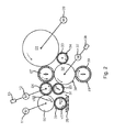
- FIG. Rolling Another embodiment of the solution found is shown in FIG. Rolling and other features corresponding to those in Fig. 1 are the same Position numbers provided.
- a difference from the device shown in FIG. 1 consists in that a dampening solution reservoir 26 and one in the dampening solution reservoir 26th immersed sixth roller 27 with preferably elastic surface 28 on the circumference are provided, wherein the sixth roller 27 is in contact with the first roller 02.
- the sixth roller 27 may be of the first roller 02 z. B. by a two rollers 02; 27 be interconnected transmission (not shown) driven or one own, from the other drives 09; 11; 12 of this device independently controllable drive (not shown). It can turn the sixth Roller 27 to be driven by a drive and by a fixed coupling, for. B.
- the first roller 02 to be driven by the sixth roller 27 may, for. B. a slip be formed by the surface velocity v02; v27 of both rolls 02; 27 be set to a preferably constant ratio to each other, for. B. on the Ratio 1: 3, wherein the first roller 02 is three times the surface speed v02 the sixth roller 27 has.
- the Surface speed v27 of the sixth roller 27 in a range of z. Eg 5% to 50%, preferably only up to 40% of the surface velocity v02 of the first Roller 02 changeable by a control of its drive, d. H. in particular by a remote control adjustable.
- the sixth roller 27 typically has one Surface velocity v27 of a maximum of 1 m / s, because above this value for the surface velocity v27 immersed in the fountain solution reservoir 26 sixth roller 27 during its rotation tends to splatter the dampening solution and the dampening solution from the sixth roller 27 from the fountain solution reservoir 26th can hardly be recorded anymore.
- the eighth roller 32 preferably has a surface 36 on the circumference made of a plastic, z. B. from a polyamide, preferably from Rilsan, on and will from a fifth drive 37, preferably independently of the other drives 09; 11; 12 of this device driven.
- this fifth drive 37 the whole Inking unit and optionally also the forme cylinder 01 and the forme cylinder 01 driving cooperating transfer cylinder.
- the third roller 07 is preferably selectively engageable with the eighth roller 32 and of this off, which is indicated in Fig. 2 by a double arrow.
- the preferably arranged eighth roller 32 may also have a second Have traction drive 38 and z. B. be designed as a Farbreibzylinder 32,
- the ninth roller 33 then has the function of an inking roller 33.
- a ink-carrying tenth roller 39 with on the circumference elastic surface 41 can for Connection of mainly the fountain solution leading rollers 04; 07 with one Inking unit (not shown) to the eighth roller 32 adjustable and off this be, which is also indicated in Fig. 2 by a double arrow.
- the Fountain solution from the first roller 02 optionally only via the second roller 04 and third roller 07 are transported to the forme cylinder 01 or it will be another Transport path over at least two of the seventh to ninth rollers 29; 32; 33 to Provided.
- the seventh to ninth roll 29; 32; 33 leading transport path can in particular at the second roller 04 and at the third Roller 07 excess ink to be returned to the inking unit.
- Im to the eighth roller 32 employed operating state reduces the seventh roller 29th Stencil, because the dampening solution and the ink on the eighth roller 32 better be rubbed.
- the drives 11; 12; 21; 37; 09 of the rollers 02; 04; 16; 32 or the forme cylinder 01 and / or the traversing drives 13; 38 are preferably as electric motors, z. B. as frequency-controlled three-phase motors, designed, the z. B. from one to Printing press belonging control station are electrically controlled.
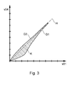
- FIG. 3 shows a characteristic diagram K for the control of Surface velocity v04 of the second roller 04 as a function of Surface velocity v01 of the forme cylinder 01.
- Representation is in a rectangular coordinate system on the abscissa of the Surface velocity v01 of the forme cylinder 01 and on the ordinate the Surface velocity v04 of the second roller 04 applied.
- both sides the bisectors H are, for example, limit characteristics G1; G2 shown, namely a lower limit characteristic G1 and an upper limit characteristic G2, which is between Characteristic field K extending to them for the control of the surface speed v04 of the second roll 04 as a function of the surface velocity v01 of the Limiting forme cylinder 01, wherein the limit characteristics G1; G2 is a linear or may have non-linear course.
- limit characteristics G1; G2 is a linear or may have non-linear course.
- the characteristic field K with the permissible relations between the Surface speed v04 of the second roller 04 and the Surface velocity v01 of the forme cylinder 01 is z. B. in a preferably stored electronic control device and is preferably programmatically evaluated, this z. B. associated with a control station of the printing press Control device at least data on the surface speed v01 of Form cylinder 01 receives and at least the control unit for controlling the drive 12 of the second roller 04 at least with removable from the characteristic field K data provided. Because in the proposed control process forms the Surface speed v01 of the forme cylinder 01 is the reference variable for the Control of the surface speed v04 of the second roller 04.
- the Control device may also limit the surface velocity v04 store second roller 04, from which the surface velocity v02 of the first Roller 02 as a function of the surface speed v04 of the second roller 04 is preferably nachumble, so that the slip between the first roller 02 and the second roller 04 remains within the specified interval.
- second tracking supplies the control unit and the Control of the drive 11 of the first roller 02 with corresponding data.
Landscapes
- Engineering & Computer Science (AREA)
- Mechanical Engineering (AREA)
- Inking, Control Or Cleaning Of Printing Machines (AREA)
- Rotary Presses (AREA)
- Rolls And Other Rotary Bodies (AREA)
- Rollers For Roller Conveyors For Transfer (AREA)
Abstract
Description
- Fig. 1
- ein erstes Ausführungsbeispiel einer Vorrichtung zum Transportieren von Feuchtmittel an die Oberfläche eines Formzylinders einer Druckmaschine mit einer eine Walze bei ihrer Rotation mit Feuchtmittel besprühenden Düse;
- Fig. 2
- ein zweites Ausführungsbeispiel einer Vorrichtung zum Transportieren von Feuchtmittel an die Oberfläche eines Formzylinders einer Druckmaschine mit einem Feuchtmittelreservoir und einer in das Feuchtmittelreservoir eintauchenden Walze;
- Fig. 3
- ein Kennlinienfeld für die Steuerung der Oberflächengeschwindigkeit der zweiten Walze in Abhängigkeit von der Oberflächengeschwindigkeit des Formzylinders.
- 01
- Formzylinder
- 02
- Walze, erste
- 03
- Oberfläche (02)
- 04
- Walze, zweite, Reibwalze, Feuchtreibzylinder
- 05
- -
- 06
- Oberfläche (04)
- 07
- Walze, dritte, Feuchtauftragwalze
- 08
- Oberfläche (07)
- 09
- Antrieb, erster (01)
- 10
- -
- 11
- Antrieb, zweiter (02)
- 12
- Antrieb, dritter (04)
- 13
- Changierantrieb, erster, Schneckentrieb, Kurbeltrieb
- 14
- Düse, Sprühbalken
- 15
- -
- 16
- Walze, vierte
- 17
- Oberfläche (16)
- 18
- Walze, fünfte, Feuchtauftragwalze
- 19
- Oberfläche (18)
- 20
- -
- 21
- Antrieb, vierter (16)
- 22
- -
- 23
- -
- 24
- -
- 25
- -
- 26
- Feuchtmittelreservoir
- 27
- Walze, sechste
- 28
- Oberfläche (27)
- 29
- Walze, siebte, Brückenwalze
- 30
- -
- 31
- Oberfläche
- 32
- Walze, achte, Farbreibzylinder
- 33
- Walze, neunte, Farbauftragwalze
- 34
- Oberfläche (33)
- 35
- -
- 36
- Oberfläche (32)
- 37
- Antrieb, fünfter (32)
- 38
- Changierantrieb, zweiter
- 39
- Walze, zehnte
- 40
- -
- 41
- Oberfläche (39)
- A
- Anpressfläche
- G1; G2
- Grenzkennlinie
- H
- Winkelhalbierende
- K
- Kennlinienfeld
- v01
- Oberflächengeschwindigkeit
- v02
- Oberflächengeschwindigkeit
- v04
- Oberflächengeschwindigkeit
- v07
- Oberflächengeschwindigkeit
- v18
- Oberflächengeschwindigkeit
- v27
- Oberflächengeschwindigkeit
Claims (48)
- Verfahren zum Transportieren von Feuchtmittel von einer ersten Walze (02) an die Oberfläche eines Formzylinders (01) einer Druckmaschine, wobei aneinandergereiht die erste Walze (02) mit einer zweiten Walze (04) und die zweite Walze (04) mit einer dritten Walze (07) in Kontakt stehen, wobei die dritte Walze (07) ihr von der ersten Walze (02) über die zweite Walze (04) zugeführtes Feuchtmittel auf den Formzylinder (01) aufträgt, wobei jeweils unabhängig von einem den Formzylinder (01) antreibenden ersten Antrieb (09) die erste Walze (02) von einem zweiten Antrieb (11) und die zweite Walze (04) von einem dritten Antrieb (12) angetrieben werden, wobei die Oberflächengeschwindigkeit (v02) der ersten Walze (02) und die Oberflächengeschwindigkeit (v04) der zweiten Walze (04) einzeln eingestellt werden, dadurch gekennzeichnet, dass die Oberflächengeschwindigkeit (v04) der zweiten Walze (04) umso näher an die Oberflächengeschwindigkeit (v01) des Formzylinders (01) herangeführt wird, je größer die Oberflächengeschwindigkeit (v01) des Formzylinders (01) ist.
- Verfahren nach Anspruch 1, dadurch gekennzeichnet, dass die Nachführung der Oberflächengeschwindigkeit (v04) der zweiten Walze (04) in Abhängigkeit von der Oberflächengeschwindigkeit (v01) des Formzylinders (01) einem linearen oder nicht-linearen Verlauf folgt.
- Verfahren nach Anspruch 1, dadurch gekennzeichnet, dass im Druckbetrieb des Formzylinders (01) die Oberflächengeschwindigkeit (v04) der zweiten Walze (04) zwischen 80% und 105% der Oberflächengeschwindigkeit (v01) des Formzylinders (01) beträgt.
- Verfahren nach Anspruch 1, dadurch gekennzeichnet, dass im Druckbetrieb des Formzylinders (01) die Oberflächengeschwindigkeit (v04) der zweiten Walze (04) zwischen 95% und 100% der Oberflächengeschwindigkeit (v01) des Formzylinders (01) beträgt.
- Verfahren nach Anspruch 1, dadurch gekennzeichnet, dass im Druckbetrieb des Formzylinders (01) die Oberflächengeschwindigkeit (v04) der zweiten Walze (04) zwischen 98% und 99,5% der Oberflächengeschwindigkeit (v01) des Formzylinders (01) beträgt.
- Verfahren nach Anspruch 1, dadurch gekennzeichnet, dass die Oberflächengeschwindigkeit (v07) der dritten Walze (07) im Wesentlichen der Oberflächengeschwindigkeit (v01) des Formzylinders (01) entspricht.
- Verfahren nach Anspruch 1, dadurch gekennzeichnet, dass die Oberflächengeschwindigkeit (v02) der ersten Walze (02) geringer als die Oberflächengeschwindigkeit (v04) der zweiten Walze (04) eingestellt wird.
- Verfahren nach Anspruch 1, dadurch gekennzeichnet, dass die zweite Walze (04) mit einem ersten Changierantrieb (13) als eine Reibwalze (04) betrieben wird.
- Verfahren nach Anspruch 8, dadurch gekennzeichnet, dass der erste Changierantrieb (13) mit dem dritten Antrieb (12) für die Rotationsbewegung der zweiten Walze (04) gekoppelt wird.
- Verfahren nach Anspruch 8, dadurch gekennzeichnet, dass die zweite Walze (04) von einem als ein Schneckentrieb (13) oder als ein Kurbeltrieb (13) ausgebildeten ersten Changierantrieb (13) betrieben wird.
- Verfahren nach Anspruch 8, dadurch gekennzeichnet, dass der erste Changierantrieb (13) unabhängig vom dritten Antrieb (12) für die Rotationsbewegung der zweiten Walze (04) betrieben wird.
- Verfahren nach Anspruch 1, dadurch gekennzeichnet, dass das Feuchtmittel mit einer eine Oberfläche (03) aus Chrom, Keramik oder Edelstahl aufweisenden ersten Walze (02) transportiert wird.
- Verfahren nach Anspruch 1, dadurch gekennzeichnet, dass das Feuchtmittel mit einer eine Oberfläche (06) aus Chrom, Keramik oder Edelstahl aufweisenden zweiten Walze (04) transportiert wird.
- Verfahren nach Anspruch 1, dadurch gekennzeichnet, dass das Feuchtmittel mit einer jeweils eine Oberfläche (06; 08) aus einem Elastomerwerkstoff bestehenden zweiten Walze (04) und dritten Walze (07) transportiert wird.
- Verfahren nach Anspruch 1, dadurch gekennzeichnet, dass das Feuchtmittel mit einer jeweils eine Oberfläche (03; 08) aus einem Elastomerwerkstoff bestehenden ersten Walze (02) und dritten Walze (07) transportiert wird.
- Verfahren nach Anspruch 1, dadurch gekennzeichnet, dass das Feuchtmittel mit einer zweiten Walze (04) mit einer im Vergleich zur Oberfläche (08) der dritten Walze (07) eine geringere Elastizität aufweisenden Oberfläche (06) transportiert wird.
- Verfahren nach Anspruch 1, dadurch gekennzeichnet, dass das Feuchtmittel mit mindestens einer Düse (14) auf die erste Walze (02) bei ihrer Rotation aufgesprüht wird.
- Verfahren nach Anspruch 1, dadurch gekennzeichnet, dass das Feuchtmittel mit einer mit Bezug auf die Druckmaschine ortsfest angeordneten Düse (14) auf die erste Walze (02) aufgesprüht wird.
- Verfahren nach Anspruch 1, dadurch gekennzeichnet, dass das Feuchtmittel mit einer mit der ersten Walze (02) in Kontakt stehenden vierten Walze (16) auf der Oberfläche (03) der ersten Walze (02) verteilt wird.
- Verfahren nach Anspruch 19, dadurch gekennzeichnet, dass die vierte Walze (16) in einer ersten Betriebsstellung an die erste Walze (02) angestellt und in einer zweiten Betriebsstellung von dieser abgestellt wird.
- Verfahren nach Anspruch 19, dadurch gekennzeichnet, dass das Feuchtmittel mit einer eine elastische Oberfläche (17) aufweisenden vierten Walze (16) verteilt wird.
- Verfahren nach Anspruch 17 und 19, dadurch gekennzeichnet, dass das von der mindestens einen Düse (14) auf die Oberfläche (03) der rotierenden ersten Walze (02) aufgesprühte Feuchtmittel vor einer Übertragung auf die zweite Walze (04) zuerst eine Kontaktstelle der ersten Walze (02) mit der vierten Walze (16) passiert.
- Verfahren nach Anspruch 19, dadurch gekennzeichnet, dass die vierte Walze (16) von einem vierten Antrieb (21) angetrieben wird.
- Verfahren nach Anspruch 1, dadurch gekennzeichnet, dass das Feuchtmittel mit einer mit der zweiten Walze (04) und dem Formzylinder (01) in Kontakt stehenden, eine elastische Oberfläche (19) aufweisenden fünften Walze (18) transportiert wird.
- Verfahren nach Anspruch 1 oder 24, dadurch gekennzeichnet, dass der Formzylinder (01) die dritte Walze (07) und/oder die fünfte Walze (18) durch Friktion oder durch ein Getriebe antreibt.
- Verfahren nach Anspruch 1, dadurch gekennzeichnet, dass das Feuchtmittel aus einem Feuchtmittelreservoir (26) mit einer in das Feuchtmittelreservoir (26) eintauchenden, mit der ersten Walze (02) in Kontakt stehenden sechsten Walze (27) transportiert wird.
- Verfahren nach Anspruch 26, dadurch gekennzeichnet, dass eine Oberflächengeschwindigkeit (v27) der sechsten Walze (27) auf einen Wert in einem Bereich von 5% bis 50% der Oberflächengeschwindigkeit (v02) der ersten Walze 02 eingestellt wird.
- Verfahren nach Anspruch 1, dadurch gekennzeichnet, dass das Feuchtmittel mit einem Walzenzug transportiert wird, bei dem aneinandergereiht die zweite Walze (04) mit einer siebten Walze (29) mit elastischer Oberfläche (31) und die siebte Walze (29) mit einer achten Walze (32) und die achte Walze (32) mit einer neunten Walze (33) mit elastischer Oberfläche (34) und die neunte Walze (33) mit dem Formzylinder (01) in Kontakt stehen.
- Verfahren nach Anspruch 28, dadurch gekennzeichnet, dass das Feuchtmittel mit einer eine Oberfläche (36) aus einem Kunststoff aufweisenden achten Walze (32) transportiert wird.
- Verfahren nach Anspruch 28, dadurch gekennzeichnet, dass das Feuchtmittel mit einer eine Oberfläche (36) aus Rilsan aufweisenden achten Walze (32) transportiert wird.
- Verfahren nach Anspruch 28, dadurch gekennzeichnet, dass die dritte Walze (07) in einer ersten Betriebsstellung an die achte Walze (32) angestellt und in einer zweiten Betriebsstellung von dieser abgestellt wird.
- Verfahren nach Anspruch 28, dadurch gekennzeichnet, dass die achte Walze (32) von einem fünften Antrieb (37) angetrieben wird.
- Verfahren nach Anspruch 28, dadurch gekennzeichnet, dass die achte Walze (32) von einen zweiten Changierantrieb (38) angetrieben wird.
- Verfahren nach Anspruch 28, dadurch gekennzeichnet, dass eine farbführende zehnte Walze (39) in einer ersten Betriebsstellung an die achte Walze (32) angestellt und in einer zweiten Betriebsstellung von dieser abgestellt wird.
- Verfahren nach Anspruch 28, dadurch gekennzeichnet, dass die siebte Walze (29) in einer ersten Betriebsstellung an die zweite Walze (04) angestellt und in einer zweiten Betriebsstellung von dieser abgestellt wird.
- Verfahren nach Anspruch 1, 8 oder 23, dadurch gekennzeichnet, dass die Walzen (02; 04; 16; 32) und/oder der Formzylinder (01) und/oder die Changierantriebe (13; 38) durch elektrisch steuerbare Motore angetrieben werden.
- Verfahren nach Anspruch 1, 8 oder 23, dadurch gekennzeichnet, dass die Walzen (02; 04; 16; 32) und/oder der Formzylinder (01) und/oder die Changierantriebe (13; 38) durch elektrisch steuerbare frequenzgesteuerte Drehstrommotore angetrieben werden.
- Verfahren nach Anspruch 1, dadurch gekennzeichnet, dass zumindest die Oberfläche (06) der zweiten Walze (04) durch eine Temperaturregelung temperiert wird.
- Verfahren nach Anspruch 1 oder 24, dadurch gekennzeichnet, dass die Oberfläche (06; 08; 19) der zweiten, dritten und/oder fünften Walze (04; 07; 18) durch eine Temperaturregelung temperiert wird.
- Verfahren nach Anspruch 1, dadurch gekennzeichnet, dass die Oberflächengeschwindigkeit (v04) der zweiten Walze (04) derart nachgeführt wird, dass die Kontaktstelle zwischen der zweiten Walze (04) und der dritten Walze (07) für das zum Formzylinder (01) zu transportierende Feuchtmittel bei einer Drehzahl des Formzylinders (01) von mehr als 45.000 Umdrehungen pro Stunde im Durchlassbetrieb verbleibt.
- Verfahren nach Anspruch 1, dadurch gekennzeichnet, dass die Oberflächengeschwindigkeit (v04) der zweiten Walze (04) derart nachgeführt wird, dass eine Temperatur an der Kontaktstelle zwischen der zweiten Walze (04) und der dritten Walze (07) bei einer Drehzahl des Formzylinders (01) von mehr als 45.000 Umdrehungen pro Stunde 40°C nicht übersteigt.
- Verfahren nach Anspruch 1, dadurch gekennzeichnet, dass die Oberflächengeschwindigkeit (v07) der dritten Walze (07) in einem konstanten Verhältnis zur Oberflächengeschwindigkeit (v01) des Formzylinders (01) eingestellt wird.
- Verfahren nach Anspruch 1, dadurch gekennzeichnet, dass bei einem an der Oberfläche des Formzylinders (01) festgestellten Mangel an Feuchtmittel ein Schlupf zwischen der zweiten Walze (04) und der dritten Walze (07) durch eine Veränderung der Oberflächengeschwindigkeit (v04) der zweiten Walze (04) verringert wird, bis die Kontaktstelle zwischen der zweiten Walze (04) und der dritten Walze (07) wieder im Durchlassbetrieb arbeitet oder die Temperatur an der Kontaktstelle zwischen der zweiten Walze (04) und der dritten Walze (07) auf 40°C oder weniger abgesunken ist.
- Verfahren nach Anspruch 1, dadurch gekennzeichnet, dass zumindest die Oberfläche (06) der zweiten Walze (04) gekühlt wird.
- Verfahren nach Anspruch 1, dadurch gekennzeichnet, dass ein Schlupf zwischen der ersten Walze (02) und der zweiten Walze (04) begrenzt wird.
- Verfahren nach Anspruch 45, dadurch gekennzeichnet, dass ab einem Grenzwert für die Oberflächengeschwindigkeit (v04) der zweiten Walze (04) zusätzlich die Oberflächengeschwindigkeit (v02) der ersten Walze (02) in Abhängigkeit von der Oberflächengeschwindigkeit (v04) der zweiten Walze (04) nachgeführt wird.
- Verfahren nach Anspruch 45, dadurch gekennzeichnet, dass ab einem Grenzwert für die Oberflächengeschwindigkeit (v04) der zweiten Walze (04) eine Notwendigkeit zur Nachführung der Oberflächengeschwindigkeit (v02) der ersten Walze (02) durch eine Meldeeinrichtung angezeigt wird.
- Verfahren nach Anspruch 1, dadurch gekennzeichnet, dass zulässige Relationen zwischen der Oberflächengeschwindigkeit (v04) der zweiten Walze (04) und der Oberflächengeschwindigkeit (v01) des Formzylinders (01) als ein Kennlinienfeld (K) gespeichert werden.
Applications Claiming Priority (2)
| Application Number | Priority Date | Filing Date | Title |
|---|---|---|---|
| DE102004006231 | 2004-02-09 | ||
| DE200410006231 DE102004006231B3 (de) | 2004-02-09 | 2004-02-09 | Verfahren zum Transportieren von Feuchtmittel von einer ersten Walze an die Oberfläche eines Formzylinders einer Druckmaschine |
Publications (2)
| Publication Number | Publication Date |
|---|---|
| EP1561578A1 true EP1561578A1 (de) | 2005-08-10 |
| EP1561578B1 EP1561578B1 (de) | 2010-10-13 |
Family
ID=34673215
Family Applications (1)
| Application Number | Title | Priority Date | Filing Date |
|---|---|---|---|
| EP05100699A Expired - Lifetime EP1561578B1 (de) | 2004-02-09 | 2005-02-02 | Verfahren zum Transportieren von Feuchtmittel von einer ersten Walze an die Oberfläche eines Formzylinders einer Druckmaschine |
Country Status (3)
| Country | Link |
|---|---|
| EP (1) | EP1561578B1 (de) |
| AT (1) | ATE484387T1 (de) |
| DE (2) | DE102004056277A1 (de) |
Cited By (1)
| Publication number | Priority date | Publication date | Assignee | Title |
|---|---|---|---|---|
| EP1698463A3 (de) * | 2005-03-03 | 2007-06-27 | MAN Roland Druckmaschinen AG | Feuchtwerk für eine Offsetdruckeinheit einer Druckmaschine |
Citations (6)
| Publication number | Priority date | Publication date | Assignee | Title |
|---|---|---|---|---|
| DE2221423A1 (de) | 1972-05-02 | 1973-11-15 | Roland Offsetmaschf | Vorrichtung zum befeuchten der druckplatte einer offsetdruckmaschine |
| DE2932105A1 (de) | 1979-08-08 | 1981-02-12 | Roland Man Druckmasch | Farbwerk fuer eine offsetrotationsdruckmaschine |
| US5649481A (en) * | 1994-12-30 | 1997-07-22 | Koenig & Bauer-Albert Aktiengesellschaft | Damping unit for a printing press |
| EP0893251A2 (de) | 1997-07-24 | 1999-01-27 | Heidelberger Druckmaschinen Aktiengesellschaft | Druckmaschine mit einem Feuchtwerk |
| US5957054A (en) * | 1996-10-21 | 1999-09-28 | Heidelberger Druckmaschinen Ag | Method for dampening a printing form for offset printing |
| WO2004054804A1 (de) | 2002-12-13 | 2004-07-01 | Koenig & Bauer Aktiengesellschaft | Verfahren zur steuerung einer ein feuchtmittel von einer feuchtmittelquelle aufnehmenden ersten walze und einer zweiten walze und feuchtwerke |
-
2004
- 2004-02-09 DE DE102004056277A patent/DE102004056277A1/de not_active Withdrawn
-
2005
- 2005-02-02 EP EP05100699A patent/EP1561578B1/de not_active Expired - Lifetime
- 2005-02-02 AT AT05100699T patent/ATE484387T1/de active
- 2005-02-02 DE DE502005010364T patent/DE502005010364D1/de not_active Expired - Lifetime
Patent Citations (6)
| Publication number | Priority date | Publication date | Assignee | Title |
|---|---|---|---|---|
| DE2221423A1 (de) | 1972-05-02 | 1973-11-15 | Roland Offsetmaschf | Vorrichtung zum befeuchten der druckplatte einer offsetdruckmaschine |
| DE2932105A1 (de) | 1979-08-08 | 1981-02-12 | Roland Man Druckmasch | Farbwerk fuer eine offsetrotationsdruckmaschine |
| US5649481A (en) * | 1994-12-30 | 1997-07-22 | Koenig & Bauer-Albert Aktiengesellschaft | Damping unit for a printing press |
| US5957054A (en) * | 1996-10-21 | 1999-09-28 | Heidelberger Druckmaschinen Ag | Method for dampening a printing form for offset printing |
| EP0893251A2 (de) | 1997-07-24 | 1999-01-27 | Heidelberger Druckmaschinen Aktiengesellschaft | Druckmaschine mit einem Feuchtwerk |
| WO2004054804A1 (de) | 2002-12-13 | 2004-07-01 | Koenig & Bauer Aktiengesellschaft | Verfahren zur steuerung einer ein feuchtmittel von einer feuchtmittelquelle aufnehmenden ersten walze und einer zweiten walze und feuchtwerke |
Cited By (1)
| Publication number | Priority date | Publication date | Assignee | Title |
|---|---|---|---|---|
| EP1698463A3 (de) * | 2005-03-03 | 2007-06-27 | MAN Roland Druckmaschinen AG | Feuchtwerk für eine Offsetdruckeinheit einer Druckmaschine |
Also Published As
| Publication number | Publication date |
|---|---|
| DE502005010364D1 (de) | 2010-11-25 |
| ATE484387T1 (de) | 2010-10-15 |
| EP1561578B1 (de) | 2010-10-13 |
| DE102004056277A1 (de) | 2005-09-08 |
Similar Documents
| Publication | Publication Date | Title |
|---|---|---|
| DE10160734B4 (de) | Druckmaschine | |
| EP1938987B1 (de) | Verfahren und Vorrichtung zur Steuerung des Farbtransportes in einem Farbwerk | |
| DE1176674B (de) | Farbwerk fuer Rotationsdruckmaschinen | |
| EP1569797B1 (de) | Verfahren zur steuerung von walzen, die ein feuchtmittel aufnehmen | |
| DE8413874U1 (de) | Vorrichtung zum Befeuchten an lithographischen Druckpressen | |
| EP1013418B1 (de) | Farbwerk | |
| CH694582A5 (de) | Kurzfarbwerk. | |
| EP0093879B1 (de) | Verfahren und Vorrichtung zum Dosieren der Farbe bei Offsetdruckmaschinen | |
| DE19921632B4 (de) | Rollenrotations-Druckmaschine mit einer Vorrichtung zum Umlenken einer nassen oder feuchten bedruckten Bahn | |
| DE3220701C3 (de) | Vorrichtung zur Feuchtmittelführung bei einem Offsetdruckwerk | |
| DE2259085A1 (de) | Farbwerk fuer flachdruckmaschinen | |
| EP0095652A2 (de) | Vorrichtung zur farbprofilabhängigen Feuchtmittelregelung | |
| DE19643354A1 (de) | Verfahren zum Befeuchten einer Druckform für den Offsetdruck | |
| DE102004006231B3 (de) | Verfahren zum Transportieren von Feuchtmittel von einer ersten Walze an die Oberfläche eines Formzylinders einer Druckmaschine | |
| EP1561578B1 (de) | Verfahren zum Transportieren von Feuchtmittel von einer ersten Walze an die Oberfläche eines Formzylinders einer Druckmaschine | |
| DE3334470C2 (de) | Farbwerk für eine Rotationsdruckmaschine | |
| DE2221289C2 (de) | Von einem Farbwerk getrennt angeordnetes Feuchtwerk für Rotationsoffsetdruckmaschinen | |
| DE69712571T2 (de) | Verfahren zum Reinigen eines Gummituchzylinders in einer Druckmachine | |
| EP0518084A1 (de) | Offsetdruckerpresse mit gesteuerter Emulsionsbildung | |
| DE3906647A1 (de) | Kurzfarbwerk | |
| EP0839652B1 (de) | Verfahren zur Reinigung von Zylindern und Walzen in einer Druckmaschine | |
| EP0951995B1 (de) | Farbwerk für eine Bogenoffsetdruckmaschine | |
| DE3611631A1 (de) | Verfahren zur minimierung von faerbungsschwankungen der drucke von offsetmaschinen | |
| EP1442884B1 (de) | Verfahren für einen stabilen Maschinenlauf an Druckeinheiten einer Rotationsdruckmaschine für den Betrieb mit teilbreitem Bedruckstoff | |
| DE10157271B4 (de) | Verfahren und Vorrichtung zur Regelung einer Temperatur eines Formzylinders |
Legal Events
| Date | Code | Title | Description |
|---|---|---|---|
| PUAI | Public reference made under article 153(3) epc to a published international application that has entered the european phase |
Free format text: ORIGINAL CODE: 0009012 |
|
| 17P | Request for examination filed |
Effective date: 20050527 |
|
| AK | Designated contracting states |
Kind code of ref document: A1 Designated state(s): AT BE BG CH CY CZ DE DK EE ES FI FR GB GR HU IE IS IT LI LT LU MC NL PL PT RO SE SI SK TR |
|
| AX | Request for extension of the european patent |
Extension state: AL BA HR LV MK YU |
|
| AKX | Designation fees paid |
Designated state(s): AT BE BG CH CY CZ DE DK EE ES FI FR GB GR HU IE IS IT LI LT LU MC NL PL PT RO SE SI SK TR |
|
| GRAP | Despatch of communication of intention to grant a patent |
Free format text: ORIGINAL CODE: EPIDOSNIGR1 |
|
| GRAC | Information related to communication of intention to grant a patent modified |
Free format text: ORIGINAL CODE: EPIDOSCIGR1 |
|
| GRAC | Information related to communication of intention to grant a patent modified |
Free format text: ORIGINAL CODE: EPIDOSCIGR1 |
|
| GRAS | Grant fee paid |
Free format text: ORIGINAL CODE: EPIDOSNIGR3 |
|
| GRAA | (expected) grant |
Free format text: ORIGINAL CODE: 0009210 |
|
| RIN1 | Information on inventor provided before grant (corrected) |
Inventor name: FISCHER, MICHAEL |
|
| AK | Designated contracting states |
Kind code of ref document: B1 Designated state(s): AT BE BG CH CY CZ DE DK EE ES FI FR GB GR HU IE IS IT LI LT LU MC NL PL PT RO SE SI SK TR |
|
| REG | Reference to a national code |
Ref country code: GB Ref legal event code: FG4D Free format text: NOT ENGLISH |
|
| REG | Reference to a national code |
Ref country code: CH Ref legal event code: EP |
|
| REG | Reference to a national code |
Ref country code: IE Ref legal event code: FG4D Free format text: LANGUAGE OF EP DOCUMENT: GERMAN |
|
| REF | Corresponds to: |
Ref document number: 502005010364 Country of ref document: DE Date of ref document: 20101125 Kind code of ref document: P |
|
| REG | Reference to a national code |
Ref country code: NL Ref legal event code: VDEP Effective date: 20101013 |
|
| LTIE | Lt: invalidation of european patent or patent extension |
Effective date: 20101013 |
|
| PG25 | Lapsed in a contracting state [announced via postgrant information from national office to epo] |
Ref country code: LT Free format text: LAPSE BECAUSE OF FAILURE TO SUBMIT A TRANSLATION OF THE DESCRIPTION OR TO PAY THE FEE WITHIN THE PRESCRIBED TIME-LIMIT Effective date: 20101013 |
|
| REG | Reference to a national code |
Ref country code: IE Ref legal event code: FD4D |
|
| PG25 | Lapsed in a contracting state [announced via postgrant information from national office to epo] |
Ref country code: BG Free format text: LAPSE BECAUSE OF FAILURE TO SUBMIT A TRANSLATION OF THE DESCRIPTION OR TO PAY THE FEE WITHIN THE PRESCRIBED TIME-LIMIT Effective date: 20110113 Ref country code: NL Free format text: LAPSE BECAUSE OF FAILURE TO SUBMIT A TRANSLATION OF THE DESCRIPTION OR TO PAY THE FEE WITHIN THE PRESCRIBED TIME-LIMIT Effective date: 20101013 Ref country code: FI Free format text: LAPSE BECAUSE OF FAILURE TO SUBMIT A TRANSLATION OF THE DESCRIPTION OR TO PAY THE FEE WITHIN THE PRESCRIBED TIME-LIMIT Effective date: 20101013 Ref country code: SI Free format text: LAPSE BECAUSE OF FAILURE TO SUBMIT A TRANSLATION OF THE DESCRIPTION OR TO PAY THE FEE WITHIN THE PRESCRIBED TIME-LIMIT Effective date: 20101013 Ref country code: SE Free format text: LAPSE BECAUSE OF FAILURE TO SUBMIT A TRANSLATION OF THE DESCRIPTION OR TO PAY THE FEE WITHIN THE PRESCRIBED TIME-LIMIT Effective date: 20101013 Ref country code: PT Free format text: LAPSE BECAUSE OF FAILURE TO SUBMIT A TRANSLATION OF THE DESCRIPTION OR TO PAY THE FEE WITHIN THE PRESCRIBED TIME-LIMIT Effective date: 20110214 Ref country code: IS Free format text: LAPSE BECAUSE OF FAILURE TO SUBMIT A TRANSLATION OF THE DESCRIPTION OR TO PAY THE FEE WITHIN THE PRESCRIBED TIME-LIMIT Effective date: 20110213 |
|
| PG25 | Lapsed in a contracting state [announced via postgrant information from national office to epo] |
Ref country code: GR Free format text: LAPSE BECAUSE OF FAILURE TO SUBMIT A TRANSLATION OF THE DESCRIPTION OR TO PAY THE FEE WITHIN THE PRESCRIBED TIME-LIMIT Effective date: 20110114 |
|
| PG25 | Lapsed in a contracting state [announced via postgrant information from national office to epo] |
Ref country code: EE Free format text: LAPSE BECAUSE OF FAILURE TO SUBMIT A TRANSLATION OF THE DESCRIPTION OR TO PAY THE FEE WITHIN THE PRESCRIBED TIME-LIMIT Effective date: 20101013 Ref country code: CZ Free format text: LAPSE BECAUSE OF FAILURE TO SUBMIT A TRANSLATION OF THE DESCRIPTION OR TO PAY THE FEE WITHIN THE PRESCRIBED TIME-LIMIT Effective date: 20101013 Ref country code: IE Free format text: LAPSE BECAUSE OF FAILURE TO SUBMIT A TRANSLATION OF THE DESCRIPTION OR TO PAY THE FEE WITHIN THE PRESCRIBED TIME-LIMIT Effective date: 20101013 Ref country code: ES Free format text: LAPSE BECAUSE OF FAILURE TO SUBMIT A TRANSLATION OF THE DESCRIPTION OR TO PAY THE FEE WITHIN THE PRESCRIBED TIME-LIMIT Effective date: 20110124 |
|
| PLBE | No opposition filed within time limit |
Free format text: ORIGINAL CODE: 0009261 |
|
| STAA | Information on the status of an ep patent application or granted ep patent |
Free format text: STATUS: NO OPPOSITION FILED WITHIN TIME LIMIT |
|
| BERE | Be: lapsed |
Owner name: KOENIG & BAUER A.G. Effective date: 20110228 |
|
| PG25 | Lapsed in a contracting state [announced via postgrant information from national office to epo] |
Ref country code: SK Free format text: LAPSE BECAUSE OF FAILURE TO SUBMIT A TRANSLATION OF THE DESCRIPTION OR TO PAY THE FEE WITHIN THE PRESCRIBED TIME-LIMIT Effective date: 20101013 Ref country code: PL Free format text: LAPSE BECAUSE OF FAILURE TO SUBMIT A TRANSLATION OF THE DESCRIPTION OR TO PAY THE FEE WITHIN THE PRESCRIBED TIME-LIMIT Effective date: 20101013 Ref country code: DK Free format text: LAPSE BECAUSE OF FAILURE TO SUBMIT A TRANSLATION OF THE DESCRIPTION OR TO PAY THE FEE WITHIN THE PRESCRIBED TIME-LIMIT Effective date: 20101013 Ref country code: RO Free format text: LAPSE BECAUSE OF FAILURE TO SUBMIT A TRANSLATION OF THE DESCRIPTION OR TO PAY THE FEE WITHIN THE PRESCRIBED TIME-LIMIT Effective date: 20101013 |
|
| 26N | No opposition filed |
Effective date: 20110714 |
|
| PG25 | Lapsed in a contracting state [announced via postgrant information from national office to epo] |
Ref country code: MC Free format text: LAPSE BECAUSE OF NON-PAYMENT OF DUE FEES Effective date: 20110228 |
|
| REG | Reference to a national code |
Ref country code: CH Ref legal event code: PL |
|
| PG25 | Lapsed in a contracting state [announced via postgrant information from national office to epo] |
Ref country code: LI Free format text: LAPSE BECAUSE OF NON-PAYMENT OF DUE FEES Effective date: 20110228 Ref country code: CH Free format text: LAPSE BECAUSE OF NON-PAYMENT OF DUE FEES Effective date: 20110228 |
|
| REG | Reference to a national code |
Ref country code: DE Ref legal event code: R097 Ref document number: 502005010364 Country of ref document: DE Effective date: 20110714 |
|
| PG25 | Lapsed in a contracting state [announced via postgrant information from national office to epo] |
Ref country code: BE Free format text: LAPSE BECAUSE OF NON-PAYMENT OF DUE FEES Effective date: 20110228 |
|
| PG25 | Lapsed in a contracting state [announced via postgrant information from national office to epo] |
Ref country code: IT Free format text: LAPSE BECAUSE OF FAILURE TO SUBMIT A TRANSLATION OF THE DESCRIPTION OR TO PAY THE FEE WITHIN THE PRESCRIBED TIME-LIMIT Effective date: 20101013 |
|
| PGFP | Annual fee paid to national office [announced via postgrant information from national office to epo] |
Ref country code: FR Payment date: 20120229 Year of fee payment: 8 |
|
| PGFP | Annual fee paid to national office [announced via postgrant information from national office to epo] |
Ref country code: DE Payment date: 20120315 Year of fee payment: 8 |
|
| PGFP | Annual fee paid to national office [announced via postgrant information from national office to epo] |
Ref country code: GB Payment date: 20120221 Year of fee payment: 8 |
|
| REG | Reference to a national code |
Ref country code: AT Ref legal event code: MM01 Ref document number: 484387 Country of ref document: AT Kind code of ref document: T Effective date: 20110202 |
|
| PG25 | Lapsed in a contracting state [announced via postgrant information from national office to epo] |
Ref country code: AT Free format text: LAPSE BECAUSE OF NON-PAYMENT OF DUE FEES Effective date: 20110202 |
|
| PG25 | Lapsed in a contracting state [announced via postgrant information from national office to epo] |
Ref country code: CY Free format text: LAPSE BECAUSE OF FAILURE TO SUBMIT A TRANSLATION OF THE DESCRIPTION OR TO PAY THE FEE WITHIN THE PRESCRIBED TIME-LIMIT Effective date: 20101013 Ref country code: LU Free format text: LAPSE BECAUSE OF NON-PAYMENT OF DUE FEES Effective date: 20110202 |
|
| PG25 | Lapsed in a contracting state [announced via postgrant information from national office to epo] |
Ref country code: TR Free format text: LAPSE BECAUSE OF FAILURE TO SUBMIT A TRANSLATION OF THE DESCRIPTION OR TO PAY THE FEE WITHIN THE PRESCRIBED TIME-LIMIT Effective date: 20101013 |
|
| GBPC | Gb: european patent ceased through non-payment of renewal fee |
Effective date: 20130202 |
|
| PG25 | Lapsed in a contracting state [announced via postgrant information from national office to epo] |
Ref country code: HU Free format text: LAPSE BECAUSE OF FAILURE TO SUBMIT A TRANSLATION OF THE DESCRIPTION OR TO PAY THE FEE WITHIN THE PRESCRIBED TIME-LIMIT Effective date: 20101013 |
|
| REG | Reference to a national code |
Ref country code: FR Ref legal event code: ST Effective date: 20131031 |
|
| REG | Reference to a national code |
Ref country code: DE Ref legal event code: R119 Ref document number: 502005010364 Country of ref document: DE Effective date: 20130903 |
|
| PG25 | Lapsed in a contracting state [announced via postgrant information from national office to epo] |
Ref country code: FR Free format text: LAPSE BECAUSE OF NON-PAYMENT OF DUE FEES Effective date: 20130228 Ref country code: GB Free format text: LAPSE BECAUSE OF NON-PAYMENT OF DUE FEES Effective date: 20130202 Ref country code: DE Free format text: LAPSE BECAUSE OF NON-PAYMENT OF DUE FEES Effective date: 20130903 |