EP1559653A1 - Verpackung mit Originalitätssicherung - Google Patents
Verpackung mit Originalitätssicherung Download PDFInfo
- Publication number
- EP1559653A1 EP1559653A1 EP05290147A EP05290147A EP1559653A1 EP 1559653 A1 EP1559653 A1 EP 1559653A1 EP 05290147 A EP05290147 A EP 05290147A EP 05290147 A EP05290147 A EP 05290147A EP 1559653 A1 EP1559653 A1 EP 1559653A1
- Authority
- EP
- European Patent Office
- Prior art keywords
- sheet
- antenna circuit
- packaging
- antenna
- envelope
- Prior art date
- Legal status (The legal status is an assumption and is not a legal conclusion. Google has not performed a legal analysis and makes no representation as to the accuracy of the status listed.)
- Granted
Links
Images


Classifications
-
- B—PERFORMING OPERATIONS; TRANSPORTING
- B65—CONVEYING; PACKING; STORING; HANDLING THIN OR FILAMENTARY MATERIAL
- B65D—CONTAINERS FOR STORAGE OR TRANSPORT OF ARTICLES OR MATERIALS, e.g. BAGS, BARRELS, BOTTLES, BOXES, CANS, CARTONS, CRATES, DRUMS, JARS, TANKS, HOPPERS, FORWARDING CONTAINERS; ACCESSORIES, CLOSURES, OR FITTINGS THEREFOR; PACKAGING ELEMENTS; PACKAGES
- B65D27/00—Envelopes or like essentially-rectangular flexible containers for postal or other purposes having no structural provision for thickness of contents
- B65D27/12—Closures
- B65D27/30—Closures with special means for indicating unauthorised opening
-
- B—PERFORMING OPERATIONS; TRANSPORTING
- B65—CONVEYING; PACKING; STORING; HANDLING THIN OR FILAMENTARY MATERIAL
- B65D—CONTAINERS FOR STORAGE OR TRANSPORT OF ARTICLES OR MATERIALS, e.g. BAGS, BARRELS, BOTTLES, BOXES, CANS, CARTONS, CRATES, DRUMS, JARS, TANKS, HOPPERS, FORWARDING CONTAINERS; ACCESSORIES, CLOSURES, OR FITTINGS THEREFOR; PACKAGING ELEMENTS; PACKAGES
- B65D27/00—Envelopes or like essentially-rectangular flexible containers for postal or other purposes having no structural provision for thickness of contents
-
- B—PERFORMING OPERATIONS; TRANSPORTING
- B65—CONVEYING; PACKING; STORING; HANDLING THIN OR FILAMENTARY MATERIAL
- B65D—CONTAINERS FOR STORAGE OR TRANSPORT OF ARTICLES OR MATERIALS, e.g. BAGS, BARRELS, BOTTLES, BOXES, CANS, CARTONS, CRATES, DRUMS, JARS, TANKS, HOPPERS, FORWARDING CONTAINERS; ACCESSORIES, CLOSURES, OR FITTINGS THEREFOR; PACKAGING ELEMENTS; PACKAGES
- B65D5/00—Rigid or semi-rigid containers of polygonal cross-section, e.g. boxes, cartons or trays, formed by folding or erecting one or more blanks made of paper
- B65D5/42—Details of containers or of foldable or erectable container blanks
- B65D5/4212—Information or decoration elements, e.g. content indicators, or for mailing
-
- G—PHYSICS
- G06—COMPUTING OR CALCULATING; COUNTING
- G06K—GRAPHICAL DATA READING; PRESENTATION OF DATA; RECORD CARRIERS; HANDLING RECORD CARRIERS
- G06K19/00—Record carriers for use with machines and with at least a part designed to carry digital markings
- G06K19/06—Record carriers for use with machines and with at least a part designed to carry digital markings characterised by the kind of the digital marking, e.g. shape, nature, code
- G06K19/067—Record carriers with conductive marks, printed circuits or semiconductor circuit elements, e.g. credit or identity cards also with resonating or responding marks without active components
- G06K19/07—Record carriers with conductive marks, printed circuits or semiconductor circuit elements, e.g. credit or identity cards also with resonating or responding marks without active components with integrated circuit chips
- G06K19/077—Constructional details, e.g. mounting of circuits in the carrier
- G06K19/07749—Constructional details, e.g. mounting of circuits in the carrier the record carrier being capable of non-contact communication, e.g. constructional details of the antenna of a non-contact smart card
- G06K19/07798—Constructional details, e.g. mounting of circuits in the carrier the record carrier being capable of non-contact communication, e.g. constructional details of the antenna of a non-contact smart card part of the antenna or the integrated circuit being adapted for rupturing or breaking, e.g. record carriers functioning as sealing devices for detecting not-authenticated opening of containers
-
- B—PERFORMING OPERATIONS; TRANSPORTING
- B65—CONVEYING; PACKING; STORING; HANDLING THIN OR FILAMENTARY MATERIAL
- B65D—CONTAINERS FOR STORAGE OR TRANSPORT OF ARTICLES OR MATERIALS, e.g. BAGS, BARRELS, BOTTLES, BOXES, CANS, CARTONS, CRATES, DRUMS, JARS, TANKS, HOPPERS, FORWARDING CONTAINERS; ACCESSORIES, CLOSURES, OR FITTINGS THEREFOR; PACKAGING ELEMENTS; PACKAGES
- B65D2203/00—Decoration means, markings, information elements, contents indicators
- B65D2203/10—Transponders
Definitions
- the present invention relates to packaging elements, such as Envelopes, boxes or packages whose integrity can be controlled electronically.
- Radio-identification technology is today very widespread in many areas. This technology is the most often implemented in tags called "radio tags" which include an electronic chip that contains information can be accessed remotely by radiofrequency by means of a reading device.
- the label is provided with a link which, once cut, prevents any possibility of reading information contained in the chip the label.
- the tag with a link is then used as a seal and is placed at the level of the parts of the object that is manipulated when it is opened.
- the link of the label is attached between the opening flap and the rest of the body of the envelope so that it can not be opened normally without cutting the link.
- this type of label does not allow to control a unauthorized opening only for cases where the packaging element has been open in a conventional manner, namely by manipulation of the means provided for its opening.
- the link is not broken and the control remote electronics integrity of the packaging is inefficient. Alone a careful visual inspection could determine that the packaging has been broken. In an industrial context such as that of a routing company for example, such a solution seems unrealistic in view of the quantities of envelopes or parcels to be treated each day.
- the present invention aims to remedy the aforementioned drawbacks and to make a package that allows to electronically control its integrity, regardless of which part of the packaging was opened.
- controllable integrity packaging comprising a hermetically sealed body, the body being shaped by folding a sheet of previously cut material according to a predefined form
- packaging according to the invention comprises a remotely interrogable electronic component formed of a means of storing data connected to an antenna circuit, said circuit antenna extending at least over the entire periphery of the surface internal of the sheet of material.
- the package according to the invention comprises means for remotely searchable storage that are useful for identification and tracking an object transported in the package while playing the role of witness of the integrity of the packaging.
- the antenna circuit being disposed on the entire periphery of the sheet of material, any opening the package from any edge of the latter will be detected since it will cause the breaking of the antenna circuit.
- the Verification of the integrity of the packaging is carried out by remote interrogation of it: if it is not possible to read the information stored in the component is that the antenna was broken following an opening fraudulent.
- the antenna circuit can extend further on the internal faces of the material sheet.
- the opening detection level is thus increased because even an opening of the package by an incision on one of the faces of the latter can be detected.
- the circuit antenna arranged on the sheet of material can describe a series ripples or zigzags.
- the memory means data and the antenna circuit of the electronic component are disposed on the inner surface of the sheet of material so as to be protected inside the packaging once it is assembled.
- a first part antenna circuit is disposed on an inner face of the material, the second complementary part of the antenna circuit being disposed on the other inner face of the sheet at a determined location in order to complete the first part of the circuit once the packaging assembled.
- the antenna circuit can consist of a very low thickness that is stuck on the inner surface of the sheet of material or a conductive ink deposited on the inner surface of the sheet of material.
- a conductive ink makes it possible to form various patterns in the antenna circuit such as ripples or zigzags for example.
- the invention applies to various types of packaging such as in particular envelopes or folding boxes used as packages.
- these include weakening portions, some the antenna circuit can pass through these portions so as to facilitate its break in case of fraudulent opening.
- this invention will be essentially described in relation to envelopes and package boxes that are commonly used packaging elements to transport documents or objects. However, it will appear clearly that the present invention applies to any other type packaging which, when assembled, forms a hermetic enclosure around the conditioned object.
- Figures 1 and 2 illustrate an embodiment of the packaging object of the present invention applied to a mail envelope Traditional.
- Figure 1 shows an envelope 100 in its shape unfolded.
- the envelope 100 is formed from a paper sheet 101 or another which is cut out according to a scheme that defines the different elements to fold and assemble to form the body of the envelope in which the object (eg documents) to be transported can be accommodated.
- the sheet 101 comprises a first portion 110 comprising three flaps 111, 112 and 113 and a second portion 120.
- the envelope is assembled by the folding portions 110 and 120 along the fold line 120a, the shutters 111 and 113 closing the lateral edges of the envelope by folding according to the lines 111a and 113a and bonding against the portion 120.
- the sheet 101 and folded and glued forms the envelope 100 in which objects, such as documents, can be introduced by the opening left free by the portion 112.
- the envelope is permanently closed well-known way using the portion 112 whose face next to the portion 120 is provided with a self-adhesive strip 114.
- the component electronics 130 is formed of an electronic chip 131 connected to a antenna 132 both disposed on an inner surface of the sheet 101.
- the antenna 132 allows the remote reading of the information contained in the chip.
- the antenna 132 is formed by a circuit or winding 133 which consists of two conductors 1331 and 1332 joining at the end of the Antenna circuit 133.
- the 1331 and 1332 conductors are also connected to the chip 131.
- the conductors 1331 and 1332 therefore form a closed circuit (loop) corresponding to the antenna circuit 133.
- any cutting one or both conductors 1331, 1332 at a location any of the antenna circuit 133 results in opening this circuit and makes impossible any transmission with the chip.
- the control of the integrity of the packaging depends on the state of the antenna circuit which is either closed and operational indication that the packaging is intact, either interrupted at one or several places testifying to an opening of the packaging.
- the presence of the electronic chip 131 and the antenna circuit 132 on the only inner surface of the envelope ensures a perfect confidentiality to this integrity check.
- the chip 131 mainly comprises an electronic circuit of memorization of data that can be accessed in reading as well as in write if necessary. Reading, and possibly writing, of data in the memory circuit is made by transmission radio frequency thanks to the antenna 132 in particular. If we interrupt the circuit which constitutes the antenna 132, it becomes inoperative and no transmission with the 131 chip can no longer be achieved, thus testifying a fraudulent opening of the envelope.
- the antenna circuit 133 In order to detect an unauthorized opening of the envelope and this, whatever the edge of the envelope cut or torn, we have the antenna circuit 133 at least over the entire periphery of the envelope (turn 133c in FIG. 1) so as to cover all the edges of the envelope. In this way, the antenna 132 passes at least once on the folding lines 111a, 112a, 113a and 120a which form the edges of the envelope 100 after assembly. So once the envelope is assembled and closed as illustrated in Figure 2, the antenna 132 is present on all the edges of the envelope and any opening attempt by any of these edges can be detected unlike the device of the prior art which makes it possible to detect only an opening by the flap 112.
- the antenna circuit 133 can also extend over the parts portions 110 and 120 (turns 133a and 133b) to enable the detection of an opening of the envelope by the main faces to front or back.
- the antenna 132 may have portions in the form of zigzags or ripples as shown on the flaps 111 and 112 of FIG. so more detection areas on the envelope so even a small incision of the envelope can be detected. More generally, the waving or zigzag angle is chosen so as to prevent any extracting a document or an object from the package. Therefore, the spacing between two undulations or zigzags is determined according to the size of the object enclosed in the package.
- portions of embrittlement which correspond to discontinuous divisions or micro-perforations at the gluing areas of the shutters so to cause the tearing of part of the flap and / or the portion of the corresponding envelope.
- portions of 141 and 142 are respectively present on panel 112 at level of the passage of the antenna circuit 133 and on the portion 120 to level of the gluing area of flap 112.
- any attempt 112 will lead to the removal of one or more parts of this and / or portion 120.
- the parts torn off the flap 112 lead to definitive breaking points in the antenna circuit. of the portions of fragilisations can of course be present on other shutters and corresponding portions of the envelope.
- FIG. 5 shows an alternative embodiment of an envelope with controllable integrity according to the invention.
- the envelope illustrated in FIG. 5 differs from that of FIG. the antenna circuit 333 are arranged both on the shutters and on the main portions of the envelope.
- part of the antenna circuit 333 is disposed on the flap 312 while another complementary part, corresponding to the parts missing from the driver 3331 on the flap 312, is arranged on the portion 320 of the opposite side of the sheet of material. So, this is only a once the envelope closed by flap and sticking the flap 312 on the portion 320 (previously folded over the portion 310 as in Figure 2) that the conductors 3331 and 3332 form a continuous path on the surface internal of the sheet of material which closes the antenna circuit 333.
- portions of embrittlement (pre-cut) 341 and / or 342 may be present in particular on the passage of the circuit 333 making impossible an opening of the envelope without tearing portions of fragilisations that lead to definitive breakpoints in the antenna circuit.
- embrittlement portions is described here in connection with envelopes but these can be implemented in any other type of packaging.
- the invention it is possible to make envelopes whose integrity can be controlled remotely with a high level of safety.
- the electronic component 130 and more particularly the antenna 132 are arranged only to inside the envelope, it is very difficult to determine the points of passage of the antenna when observing the envelope of the outside.
- the component 130 is further protected inside the envelope, which prevents the latter from being damaged by manipulations of envelope during sorting or transport.
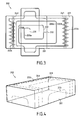
- FIGs 3 and 4 illustrate a second embodiment of the package according to the invention which is this time applied to a box folding 200 such as those commonly used for postal parcels.
- the principle implemented is the same as previously described in relation with the envelope 100 illustrated in Figures 1 and 2.
- an electronic component 230 formed of an electronic chip 231 connected to an antenna 232, is arranged on the inner surface of a sheet 201 of cardboard or the like.
- the antenna 232 extends at least in the vicinity of the entire periphery of the envelope (turn 233c in FIG. 1) so as to cover all the edges of the box 200.
- the circuit 233 of the antenna 232 passes at least one fold lines that form the edge of the box 200 after assembly ( Figure 4).
- the circuit antenna 233 can also extend over the main faces to the inside of the box 200 (turns 233a and 233b) so as to cover also the faces of the latter (i.e. lid, bottom and side faces). Therefore, an opening made on one of the surfaces of the box can also be detected.
- the antenna can be arranged according to a conventional winding or in a wavy or zigzag shape in order to multiply again the detection zones in the box.
- box-type packaging may include portions of fragilization serving as opening witnesses. These portions weakened by a pre-cut are irreparably torn off during the opening of the packaging thus making it possible to visually observe an opening of the box even if the parts of openings are glued.
- Such witnesses are represented on box 200 in figures 3 and 4. They are formed by a series of pre-cut circles 241 and 242 respectively disposed at level flaps 212 and 221 by which one opens the box.
- the antenna circuits 133 or 233 described above may be formed with a very thin flat conductive wire that is glued to the surface inside the sheet of material before assembly or by means of of a conductive ink deposited by printing on the inner surface of the sheet of material.
- the formation of the antenna by deposit (printing) of a conductive ink makes it possible to perform various forms of a easy way, facilitating in particular the formation of corrugations or zigzags in the antenna circuit.
- antenna circuit forms described above are not as some examples of possible configurations of an antenna circuit.
- the skilled person will readily consider any other form of circuit adapted to the shape or dimensions of the packaging or to needs to secure the particular packaging.
- the invention proposes a package which comprises means which not only allow identification and monitoring remote but also a quick and secure control of the integrity of packaging. This control does not require the implementation of other than those usually used, since the check is carried out during reading information stored in the electronic chip. In If the reader can not read the stored information, it is because the antenna circuit was broken during a fraudulent opening of packaging.
- reading stored data can be carried out for example using a reader portable (not shown) which mainly comprises a screen display, a keypad and means for activating the chip (transponder) radio frequency (RF).
- a reader portable not shown
- RF radio frequency
- These activation means send a radiofrequency wave to the chip via the antenna fixed in the package.
- the received wave charges a capacitance present in the circuit of the chip which, when the capacity is discharged, returns to the reader a code or information, written in the memory of the chip.
- the code and / or the information of each chip questioned are thus sent to the reader and displayed on its screen and / or stored in a memory, or transferred via a serial link to a computer of treatment for sorting or tracking the packaging.
- non-portable drives such as a gantry type reader which packaging scrolls, which have antenna geometries allowing serial reading at a greater distance.
Landscapes
- Engineering & Computer Science (AREA)
- Mechanical Engineering (AREA)
- Microelectronics & Electronic Packaging (AREA)
- Computer Hardware Design (AREA)
- Physics & Mathematics (AREA)
- General Physics & Mathematics (AREA)
- Theoretical Computer Science (AREA)
- Burglar Alarm Systems (AREA)
- Details Of Rigid Or Semi-Rigid Containers (AREA)
- Cartons (AREA)
- Packages (AREA)
Applications Claiming Priority (2)
| Application Number | Priority Date | Filing Date | Title |
|---|---|---|---|
| FR0400900A FR2865720B1 (fr) | 2004-01-30 | 2004-01-30 | Emballage a integrite controlable |
| FR0400900 | 2004-01-30 |
Publications (2)
| Publication Number | Publication Date |
|---|---|
| EP1559653A1 true EP1559653A1 (de) | 2005-08-03 |
| EP1559653B1 EP1559653B1 (de) | 2007-05-23 |
Family
ID=34639812
Family Applications (1)
| Application Number | Title | Priority Date | Filing Date |
|---|---|---|---|
| EP05290147A Ceased EP1559653B1 (de) | 2004-01-30 | 2005-01-24 | Verpackung mit Originalitätssicherung |
Country Status (5)
| Country | Link |
|---|---|
| US (1) | US7301460B2 (de) |
| EP (1) | EP1559653B1 (de) |
| CA (1) | CA2494401C (de) |
| DE (1) | DE602005001159T2 (de) |
| FR (1) | FR2865720B1 (de) |
Cited By (4)
| Publication number | Priority date | Publication date | Assignee | Title |
|---|---|---|---|---|
| WO2008065278A3 (fr) * | 2006-11-06 | 2008-07-31 | Id3S Identification Solutions | Dispositif d'identification par radiofrequence et procede de realisation d'un tel dispositif |
| WO2011132187A1 (en) * | 2010-04-18 | 2011-10-27 | Gevaram Quality Envelopes Ltd. | Tamper-resistant envelope |
| WO2020033533A1 (en) * | 2018-08-07 | 2020-02-13 | Avery Dennison Retail Information Services, Llc | Overlapping coil structures formed by folding for compact rfid tags |
| US11798901B1 (en) | 2018-10-31 | 2023-10-24 | Avery Dennison Retail Information Services Llc | Wafer-scale integration with alternative technology wafer processes that can be folded into three-dimensional packaging |
Families Citing this family (44)
| Publication number | Priority date | Publication date | Assignee | Title |
|---|---|---|---|---|
| ATE393423T1 (de) * | 2003-10-24 | 2008-05-15 | Verifone Systems Ireland Ltd | Schaltungs-sicherheit |
| US20060220855A1 (en) * | 2005-03-18 | 2006-10-05 | Hartmann Clinton S | Tamper indicating saw tag system and method for using same |
| JP2006341858A (ja) * | 2005-06-07 | 2006-12-21 | Matsushita Electric Ind Co Ltd | 包装商品に対するicタグの装着方法 |
| DE102005048653A1 (de) * | 2005-10-08 | 2007-04-19 | Lindenau, Andreas | Mit einem elektronischen Schaltkreis verbundene Verpackung |
| US7388506B2 (en) | 2006-02-07 | 2008-06-17 | Rexam Healthcare Packaging Inc. | Closure and package with induction seal and RFID tag |
| WO2007106584A2 (en) * | 2006-03-15 | 2007-09-20 | Angel Secure Networks, Inc. | Secure panel with remotely controlled embedded devices |
| US7576653B2 (en) * | 2006-03-15 | 2009-08-18 | Angel Secure Networks, Inc. | Secure panel with remotely controlled embedded devices |
| WO2007149995A2 (en) * | 2006-06-21 | 2007-12-27 | Velcro Industries B.V. | Making and securing identification tags |
| US8344885B2 (en) | 2008-01-22 | 2013-01-01 | Angel Secure Networks Inc. | Container with interior enclosure of composite material having embedded security element |
| US7755489B2 (en) * | 2008-04-28 | 2010-07-13 | Honeywell International Inc. | Intelligent packaging method and system based on acoustic wave devices |
| US20090284377A1 (en) * | 2008-05-15 | 2009-11-19 | Keystone Technology Solutions, Llc | Flexible RFID Label |
| US8531298B2 (en) | 2008-05-15 | 2013-09-10 | Round Rock Research, Llc | Flexible RFID label |
| US8698627B2 (en) * | 2009-01-07 | 2014-04-15 | Meadwestvaco Corporation | Security packaging |
| US9112545B2 (en) * | 2009-02-09 | 2015-08-18 | Gui-Yang Lu | Resonant-circuit structure |
| US8432300B2 (en) * | 2009-03-26 | 2013-04-30 | Hypercom Corporation | Keypad membrane security |
| EP2314515B1 (de) * | 2009-10-21 | 2013-03-27 | Deutsche Post AG | Originalitätsverschluss für eine Schachtel mit einem Alarmsensor |
| GB201020947D0 (en) * | 2010-12-10 | 2011-01-26 | Maxgear Europ Ltd | Security sticker |
| US8577335B2 (en) | 2011-06-08 | 2013-11-05 | Kitaru Innovations Inc. | Method and apparatus for tracking package deliveries |
| EP2734987A1 (de) * | 2011-07-19 | 2014-05-28 | Dubois Ltd. | Produktbehälter oder -verpackung mit einer sicherheitsvorrichtung |
| JP5803538B2 (ja) * | 2011-10-06 | 2015-11-04 | 凸版印刷株式会社 | Icタグ付き容器及びicタグ付き蓋部材 |
| WO2013078484A1 (en) * | 2011-11-27 | 2013-05-30 | Isaac Neuman | Diamond-based tradeable instrument security system |
| CN202650055U (zh) * | 2012-05-08 | 2013-01-02 | 永丰精密电子(扬州)有限公司 | 射频识别标签 |
| DE102013203462A1 (de) * | 2013-02-28 | 2014-08-28 | Id-Diamonds Gmbh | Aufnahmebehältnis für Wertgegenstände, insbesondere für Diamanten, andere Edelsteine oder Perlen |
| EP3105704A4 (de) * | 2014-02-12 | 2017-09-27 | Secured Worldwide LLC | Sichere diamantchipkarten und austauschsysteme dafür |
| US9418329B2 (en) * | 2014-10-30 | 2016-08-16 | WaveMark, Inc. | Product holder |
| DE102014223256A1 (de) * | 2014-11-14 | 2016-05-19 | Robert Bosch Gmbh | Vorrichtung zur Öffnungssensierung einer Verpackung sowie Verfahren zur Herstellung der Vorrichtung |
| EP3190065B2 (de) * | 2016-01-08 | 2022-04-27 | Reemtsma Cigarettenfabriken GmbH | Verpackung mit einem informationscodierungsmuster |
| JP6735128B2 (ja) * | 2016-03-30 | 2020-08-05 | セコム株式会社 | 封印具及びそれを用いた封印方法 |
| US9934665B1 (en) | 2016-09-16 | 2018-04-03 | Ningsheng Zhang | Box edge security device |
| WO2018108224A1 (en) | 2016-12-16 | 2018-06-21 | Cgi Danmark A/S | Rfid tag |
| IT201600129333A1 (it) * | 2016-12-21 | 2018-06-21 | Igb Srl | Contenitore ad evidenza di manomissione e procedimento per la realizzazione dello stesso. |
| JP6878193B2 (ja) * | 2017-07-31 | 2021-05-26 | 北越パッケージ株式会社 | 紙器 |
| US11200478B2 (en) | 2018-01-25 | 2021-12-14 | Hewlett-Packard Development Company, L.P. | Security device for product packaging |
| IT201800005410A1 (it) * | 2018-05-16 | 2019-11-16 | Imballaggio in cartone ondulato idoneo a rilevare effrazioni compiute a danno dello stesso | |
| US20200320903A1 (en) * | 2019-04-04 | 2020-10-08 | Opticallock, Inc. | Variable pattern shield protection system for a tamper-evident container |
| US11685580B2 (en) * | 2019-08-07 | 2023-06-27 | International Business Machines Corporation | Medication counterfeit detection |
| IT201900019796A1 (it) * | 2019-10-25 | 2021-04-25 | A Z Solutions S R L | Contenitore per oggetti comprendente un tag elettronico, nonche’ metodo di realizzazione dello stesso |
| FR3108427A1 (fr) * | 2020-03-18 | 2021-09-24 | Keopack | Système d’acheminement d’un objet mettant en œuvre un colis cargo transportant un colis passager, avec détection automatique de la destination du colis passager |
| IT202000009829A1 (it) * | 2020-05-05 | 2021-11-05 | Nolecom Srl | Dispositivo per la certificazione di documenti |
| CN112061551B (zh) * | 2020-09-08 | 2022-05-27 | 拍拍看(海南)人工智能有限公司 | 防打孔保险包装物 |
| CN113173338B (zh) * | 2020-09-08 | 2022-11-15 | 拍拍看(海南)人工智能有限公司 | 智能感应防打孔保险包装物 |
| EP4033407B1 (de) * | 2021-01-26 | 2023-11-01 | Société BIC | Papierhandwerkliche digitalisierung |
| FR3129142B1 (fr) * | 2021-11-15 | 2024-03-01 | Sigfox | Emballage connecté et procédé d’activation associé |
| WO2025173040A2 (en) * | 2024-02-14 | 2025-08-21 | Seshaasai Business Forms Pvt. Ltd | Tamper evident container and method of manufacturing thereof |
Citations (4)
| Publication number | Priority date | Publication date | Assignee | Title |
|---|---|---|---|---|
| US5497140A (en) * | 1992-08-12 | 1996-03-05 | Micron Technology, Inc. | Electrically powered postage stamp or mailing or shipping label operative with radio frequency (RF) communication |
| US6259369B1 (en) * | 1999-09-30 | 2001-07-10 | Moore North America, Inc. | Low cost long distance RFID reading |
| EP1162480A2 (de) * | 2000-06-05 | 2001-12-12 | cubit electronics Gmbh | Kontaktloser Transponder |
| EP1291818A1 (de) * | 2001-08-15 | 2003-03-12 | Datamars SA | Transponder |
Family Cites Families (9)
| Publication number | Priority date | Publication date | Assignee | Title |
|---|---|---|---|---|
| GB2182176B (en) * | 1985-09-25 | 1989-09-20 | Ncr Co | Data security device for protecting stored data |
| GB9115972D0 (en) * | 1991-07-24 | 1991-09-11 | Gore W L & Ass Uk | Improvements in security enclosures |
| CA2125786C (fr) * | 1991-12-19 | 2007-07-31 | Ake Gustafson | Dispositif de scellement de securite |
| US5233505A (en) * | 1991-12-30 | 1993-08-03 | Yeng-Ming Chang | Security device for protecting electronically-stored data |
| GB2270785B (en) * | 1992-09-22 | 1996-05-08 | Gore & Ass | Improvements in security enclosure manufacture |
| US6107920A (en) * | 1998-06-09 | 2000-08-22 | Motorola, Inc. | Radio frequency identification tag having an article integrated antenna |
| US6100804A (en) * | 1998-10-29 | 2000-08-08 | Intecmec Ip Corp. | Radio frequency identification system |
| US6703935B1 (en) * | 2001-05-14 | 2004-03-09 | Amerasia International Technology, Inc. | Antenna arrangement for RFID smart tags |
| US20030173397A1 (en) * | 2002-03-14 | 2003-09-18 | Kourakov Konstantin Anatolievich | Self-open envelope |
-
2004
- 2004-01-30 FR FR0400900A patent/FR2865720B1/fr not_active Expired - Fee Related
-
2005
- 2005-01-24 EP EP05290147A patent/EP1559653B1/de not_active Ceased
- 2005-01-24 DE DE602005001159T patent/DE602005001159T2/de not_active Expired - Lifetime
- 2005-01-25 CA CA2494401A patent/CA2494401C/fr not_active Expired - Lifetime
- 2005-01-28 US US11/046,059 patent/US7301460B2/en not_active Expired - Lifetime
Patent Citations (4)
| Publication number | Priority date | Publication date | Assignee | Title |
|---|---|---|---|---|
| US5497140A (en) * | 1992-08-12 | 1996-03-05 | Micron Technology, Inc. | Electrically powered postage stamp or mailing or shipping label operative with radio frequency (RF) communication |
| US6259369B1 (en) * | 1999-09-30 | 2001-07-10 | Moore North America, Inc. | Low cost long distance RFID reading |
| EP1162480A2 (de) * | 2000-06-05 | 2001-12-12 | cubit electronics Gmbh | Kontaktloser Transponder |
| EP1291818A1 (de) * | 2001-08-15 | 2003-03-12 | Datamars SA | Transponder |
Cited By (5)
| Publication number | Priority date | Publication date | Assignee | Title |
|---|---|---|---|---|
| WO2008065278A3 (fr) * | 2006-11-06 | 2008-07-31 | Id3S Identification Solutions | Dispositif d'identification par radiofrequence et procede de realisation d'un tel dispositif |
| US8640962B2 (en) | 2006-11-06 | 2014-02-04 | ID3S—Identification Solutions Systems & Services | Radiofrequency identification device and method for producing said device |
| WO2011132187A1 (en) * | 2010-04-18 | 2011-10-27 | Gevaram Quality Envelopes Ltd. | Tamper-resistant envelope |
| WO2020033533A1 (en) * | 2018-08-07 | 2020-02-13 | Avery Dennison Retail Information Services, Llc | Overlapping coil structures formed by folding for compact rfid tags |
| US11798901B1 (en) | 2018-10-31 | 2023-10-24 | Avery Dennison Retail Information Services Llc | Wafer-scale integration with alternative technology wafer processes that can be folded into three-dimensional packaging |
Also Published As
| Publication number | Publication date |
|---|---|
| CA2494401A1 (fr) | 2005-07-30 |
| FR2865720A1 (fr) | 2005-08-05 |
| EP1559653B1 (de) | 2007-05-23 |
| FR2865720B1 (fr) | 2008-06-06 |
| CA2494401C (fr) | 2012-09-25 |
| DE602005001159T2 (de) | 2008-01-17 |
| US20050184871A1 (en) | 2005-08-25 |
| US7301460B2 (en) | 2007-11-27 |
| DE602005001159D1 (de) | 2007-07-05 |
Similar Documents
| Publication | Publication Date | Title |
|---|---|---|
| CA2494401C (fr) | Emballage a integrite controlable | |
| US9846835B2 (en) | NFC/RF mechanism with multiple valid states for detecting an open container, and methods of making and using the same | |
| AU2021283960A1 (en) | Self-sealing container | |
| EP4326638B1 (de) | Paket mit einem siegel | |
| FR2717593A1 (fr) | Contenant comprenant un moyen d'identification électronique et visuel. | |
| EP0861788B1 (de) | Wellpappeverpackung versehen mit einem Informationsaufnahme- und Identifizierungsmittel | |
| WO2014006279A1 (fr) | Dispositif d'empaquetage de marchandise à acheminer par un transporteur | |
| EP0698561B1 (de) | Aus einem heissschrumpfbaren Kunststoffschlauch hergestellte Verpackungshülle | |
| EP1082256A1 (de) | Hitzeschrumpfende sicherheitsmanschette mit einem identifikationsband | |
| WO2000021026A1 (fr) | Emballage anti-fraude pour carte a circuit integre comportant des moyens de communication a distance | |
| EP1914170B1 (de) | Karton mit ausdehnbarem Volumen | |
| EP1577221A1 (de) | Verpackung aus halbsteifem Material mit Einbruchschutzelement | |
| WO2014146899A1 (fr) | Enveloppe de securite apte a assurer une protection anti-ouverture de recipients, objet recouvert d'une telle enveloppe et procede d'inscription d'informations sur une telle enveloppe | |
| JP2005231707A (ja) | 改ざん防止用箱 | |
| EP2340944B1 (de) | Glückwunschkarte mit integriertem Briefumschlag | |
| FR2787420A1 (fr) | Emballage d'expedition avec securite supplementaire | |
| FR2816923A1 (fr) | Emballage unitaire d'objet fragile ou non de differentes formes et dimensions entrant dans un cabarit admissible | |
| EP4337557B1 (de) | Verpackung mit einem an einen inhalt anpassbaren speichervolumen | |
| EP1837811A1 (de) | Verfahren zur Herstellung eines elektronischen RFID-Etiketts | |
| EP3318505B1 (de) | Sicherheitshülle und behälter, der mit einer solchen hülle abgedeckt ist | |
| EP1538089A1 (de) | Verpackungsschachtel mit Originalitätssicherung sowie Zuschnitt zum Herstellen derselben | |
| EP0637903B1 (de) | Anordnung zum Verteilen von Karten | |
| WO2022200295A1 (fr) | Procédé d'envois de colis emballés dans un emballage | |
| EP1006004A1 (de) | Unterschriften- oder Sortiermappe mit einem einschiebaren Merkzeichnensystem | |
| FR2780191A1 (fr) | Vignette adhesive comportant un certificat rendu infalsifiable |
Legal Events
| Date | Code | Title | Description |
|---|---|---|---|
| PUAI | Public reference made under article 153(3) epc to a published international application that has entered the european phase |
Free format text: ORIGINAL CODE: 0009012 |
|
| AK | Designated contracting states |
Kind code of ref document: A1 Designated state(s): AT BE BG CH CY CZ DE DK EE ES FI FR GB GR HU IE IS IT LI LT LU MC NL PL PT RO SE SI SK TR |
|
| AX | Request for extension of the european patent |
Extension state: AL BA HR LV MK YU |
|
| 17P | Request for examination filed |
Effective date: 20060109 |
|
| AKX | Designation fees paid |
Designated state(s): DE FR GB |
|
| RAP1 | Party data changed (applicant data changed or rights of an application transferred) |
Owner name: NEOPOST TECHNOLOGIES |
|
| 17Q | First examination report despatched |
Effective date: 20060213 |
|
| GRAP | Despatch of communication of intention to grant a patent |
Free format text: ORIGINAL CODE: EPIDOSNIGR1 |
|
| GRAS | Grant fee paid |
Free format text: ORIGINAL CODE: EPIDOSNIGR3 |
|
| GRAA | (expected) grant |
Free format text: ORIGINAL CODE: 0009210 |
|
| AK | Designated contracting states |
Kind code of ref document: B1 Designated state(s): DE FR GB |
|
| REG | Reference to a national code |
Ref country code: GB Ref legal event code: FG4D Free format text: NOT ENGLISH |
|
| REF | Corresponds to: |
Ref document number: 602005001159 Country of ref document: DE Date of ref document: 20070705 Kind code of ref document: P |
|
| GBT | Gb: translation of ep patent filed (gb section 77(6)(a)/1977) |
Effective date: 20070822 |
|
| PLBE | No opposition filed within time limit |
Free format text: ORIGINAL CODE: 0009261 |
|
| STAA | Information on the status of an ep patent application or granted ep patent |
Free format text: STATUS: NO OPPOSITION FILED WITHIN TIME LIMIT |
|
| 26N | No opposition filed |
Effective date: 20080226 |
|
| REG | Reference to a national code |
Ref country code: FR Ref legal event code: PLFP Year of fee payment: 12 |
|
| REG | Reference to a national code |
Ref country code: FR Ref legal event code: PLFP Year of fee payment: 13 |
|
| REG | Reference to a national code |
Ref country code: FR Ref legal event code: PLFP Year of fee payment: 14 |
|
| PGFP | Annual fee paid to national office [announced via postgrant information from national office to epo] |
Ref country code: GB Payment date: 20220119 Year of fee payment: 18 Ref country code: DE Payment date: 20220119 Year of fee payment: 18 |
|
| PGFP | Annual fee paid to national office [announced via postgrant information from national office to epo] |
Ref country code: FR Payment date: 20220119 Year of fee payment: 18 |
|
| REG | Reference to a national code |
Ref country code: DE Ref legal event code: R119 Ref document number: 602005001159 Country of ref document: DE |
|
| GBPC | Gb: european patent ceased through non-payment of renewal fee |
Effective date: 20230124 |
|
| PG25 | Lapsed in a contracting state [announced via postgrant information from national office to epo] |
Ref country code: GB Free format text: LAPSE BECAUSE OF NON-PAYMENT OF DUE FEES Effective date: 20230124 Ref country code: DE Free format text: LAPSE BECAUSE OF NON-PAYMENT OF DUE FEES Effective date: 20230801 |
|
| PG25 | Lapsed in a contracting state [announced via postgrant information from national office to epo] |
Ref country code: FR Free format text: LAPSE BECAUSE OF NON-PAYMENT OF DUE FEES Effective date: 20230131 |