EP1559153B1 - Electrode, procede de fabrication d'une electrode et batterie bipolaire - Google Patents
Electrode, procede de fabrication d'une electrode et batterie bipolaire Download PDFInfo
- Publication number
- EP1559153B1 EP1559153B1 EP03810729.8A EP03810729A EP1559153B1 EP 1559153 B1 EP1559153 B1 EP 1559153B1 EP 03810729 A EP03810729 A EP 03810729A EP 1559153 B1 EP1559153 B1 EP 1559153B1
- Authority
- EP
- European Patent Office
- Prior art keywords
- electrode
- metal carrier
- carrier
- active material
- powder
- Prior art date
- Legal status (The legal status is an assumption and is not a legal conclusion. Google has not performed a legal analysis and makes no representation as to the accuracy of the status listed.)
- Expired - Lifetime
Links
- 238000004519 manufacturing process Methods 0.000 title claims description 19
- 238000000034 method Methods 0.000 title claims description 18
- 239000000843 powder Substances 0.000 claims description 43
- 229910052755 nonmetal Inorganic materials 0.000 claims description 28
- 239000011149 active material Substances 0.000 claims description 16
- 238000005520 cutting process Methods 0.000 claims description 6
- 229920000642 polymer Polymers 0.000 claims description 6
- 239000007774 positive electrode material Substances 0.000 claims description 6
- 239000003792 electrolyte Substances 0.000 claims description 4
- 239000007773 negative electrode material Substances 0.000 claims description 3
- 239000002861 polymer material Substances 0.000 claims 3
- PXHVJJICTQNCMI-UHFFFAOYSA-N Nickel Chemical compound [Ni] PXHVJJICTQNCMI-UHFFFAOYSA-N 0.000 description 8
- 239000000463 material Substances 0.000 description 7
- 239000002184 metal Substances 0.000 description 7
- 229910052751 metal Inorganic materials 0.000 description 7
- 230000008901 benefit Effects 0.000 description 6
- 239000000835 fiber Substances 0.000 description 4
- 229910052759 nickel Inorganic materials 0.000 description 4
- 229910005813 NiMH Inorganic materials 0.000 description 3
- NPURPEXKKDAKIH-UHFFFAOYSA-N iodoimino(oxo)methane Chemical compound IN=C=O NPURPEXKKDAKIH-UHFFFAOYSA-N 0.000 description 3
- 238000003825 pressing Methods 0.000 description 3
- 239000000758 substrate Substances 0.000 description 3
- 230000004888 barrier function Effects 0.000 description 2
- 239000002482 conductive additive Substances 0.000 description 2
- 230000001419 dependent effect Effects 0.000 description 2
- 230000002209 hydrophobic effect Effects 0.000 description 2
- 230000007246 mechanism Effects 0.000 description 2
- 229910052987 metal hydride Inorganic materials 0.000 description 2
- 230000008569 process Effects 0.000 description 2
- 230000003319 supportive effect Effects 0.000 description 2
- OKTJSMMVPCPJKN-UHFFFAOYSA-N Carbon Chemical compound [C] OKTJSMMVPCPJKN-UHFFFAOYSA-N 0.000 description 1
- 239000004743 Polypropylene Substances 0.000 description 1
- 230000000712 assembly Effects 0.000 description 1
- 238000000429 assembly Methods 0.000 description 1
- 239000011230 binding agent Substances 0.000 description 1
- 229910052799 carbon Inorganic materials 0.000 description 1
- 239000012876 carrier material Substances 0.000 description 1
- 230000008859 change Effects 0.000 description 1
- 229910017052 cobalt Inorganic materials 0.000 description 1
- 239000010941 cobalt Substances 0.000 description 1
- GUTLYIVDDKVIGB-UHFFFAOYSA-N cobalt atom Chemical compound [Co] GUTLYIVDDKVIGB-UHFFFAOYSA-N 0.000 description 1
- 238000005056 compaction Methods 0.000 description 1
- 230000006835 compression Effects 0.000 description 1
- 238000007906 compression Methods 0.000 description 1
- 239000004020 conductor Substances 0.000 description 1
- 238000010276 construction Methods 0.000 description 1
- 239000004744 fabric Substances 0.000 description 1
- 150000004681 metal hydrides Chemical class 0.000 description 1
- BFDHFSHZJLFAMC-UHFFFAOYSA-L nickel(ii) hydroxide Chemical compound [OH-].[OH-].[Ni+2] BFDHFSHZJLFAMC-UHFFFAOYSA-L 0.000 description 1
- 239000012811 non-conductive material Substances 0.000 description 1
- 239000002245 particle Substances 0.000 description 1
- -1 polypropylene Polymers 0.000 description 1
- 229920001155 polypropylene Polymers 0.000 description 1
- 238000005096 rolling process Methods 0.000 description 1
- 238000007789 sealing Methods 0.000 description 1
- 238000007493 shaping process Methods 0.000 description 1
- 238000007873 sieving Methods 0.000 description 1
- 238000003892 spreading Methods 0.000 description 1
- 230000007480 spreading Effects 0.000 description 1
Images

Classifications
-
- H—ELECTRICITY
- H01—ELECTRIC ELEMENTS
- H01M—PROCESSES OR MEANS, e.g. BATTERIES, FOR THE DIRECT CONVERSION OF CHEMICAL ENERGY INTO ELECTRICAL ENERGY
- H01M10/00—Secondary cells; Manufacture thereof
- H01M10/24—Alkaline accumulators
- H01M10/28—Construction or manufacture
- H01M10/281—Large cells or batteries with stacks of plate-like electrodes
- H01M10/282—Large cells or batteries with stacks of plate-like electrodes with bipolar electrodes
-
- H—ELECTRICITY
- H01—ELECTRIC ELEMENTS
- H01M—PROCESSES OR MEANS, e.g. BATTERIES, FOR THE DIRECT CONVERSION OF CHEMICAL ENERGY INTO ELECTRICAL ENERGY
- H01M4/00—Electrodes
- H01M4/02—Electrodes composed of, or comprising, active material
- H01M4/04—Processes of manufacture in general
- H01M4/043—Processes of manufacture in general involving compressing or compaction
-
- H—ELECTRICITY
- H01—ELECTRIC ELEMENTS
- H01M—PROCESSES OR MEANS, e.g. BATTERIES, FOR THE DIRECT CONVERSION OF CHEMICAL ENERGY INTO ELECTRICAL ENERGY
- H01M4/00—Electrodes
- H01M4/02—Electrodes composed of, or comprising, active material
- H01M4/24—Electrodes for alkaline accumulators
- H01M4/26—Processes of manufacture
- H01M4/30—Pressing
-
- H—ELECTRICITY
- H01—ELECTRIC ELEMENTS
- H01M—PROCESSES OR MEANS, e.g. BATTERIES, FOR THE DIRECT CONVERSION OF CHEMICAL ENERGY INTO ELECTRICAL ENERGY
- H01M4/00—Electrodes
- H01M4/02—Electrodes composed of, or comprising, active material
- H01M4/64—Carriers or collectors
- H01M4/66—Selection of materials
-
- H—ELECTRICITY
- H01—ELECTRIC ELEMENTS
- H01M—PROCESSES OR MEANS, e.g. BATTERIES, FOR THE DIRECT CONVERSION OF CHEMICAL ENERGY INTO ELECTRICAL ENERGY
- H01M4/00—Electrodes
- H01M4/02—Electrodes composed of, or comprising, active material
- H01M2004/026—Electrodes composed of, or comprising, active material characterised by the polarity
- H01M2004/029—Bipolar electrodes
-
- Y—GENERAL TAGGING OF NEW TECHNOLOGICAL DEVELOPMENTS; GENERAL TAGGING OF CROSS-SECTIONAL TECHNOLOGIES SPANNING OVER SEVERAL SECTIONS OF THE IPC; TECHNICAL SUBJECTS COVERED BY FORMER USPC CROSS-REFERENCE ART COLLECTIONS [XRACs] AND DIGESTS
- Y02—TECHNOLOGIES OR APPLICATIONS FOR MITIGATION OR ADAPTATION AGAINST CLIMATE CHANGE
- Y02E—REDUCTION OF GREENHOUSE GAS [GHG] EMISSIONS, RELATED TO ENERGY GENERATION, TRANSMISSION OR DISTRIBUTION
- Y02E60/00—Enabling technologies; Technologies with a potential or indirect contribution to GHG emissions mitigation
- Y02E60/10—Energy storage using batteries
-
- Y—GENERAL TAGGING OF NEW TECHNOLOGICAL DEVELOPMENTS; GENERAL TAGGING OF CROSS-SECTIONAL TECHNOLOGIES SPANNING OVER SEVERAL SECTIONS OF THE IPC; TECHNICAL SUBJECTS COVERED BY FORMER USPC CROSS-REFERENCE ART COLLECTIONS [XRACs] AND DIGESTS
- Y02—TECHNOLOGIES OR APPLICATIONS FOR MITIGATION OR ADAPTATION AGAINST CLIMATE CHANGE
- Y02P—CLIMATE CHANGE MITIGATION TECHNOLOGIES IN THE PRODUCTION OR PROCESSING OF GOODS
- Y02P70/00—Climate change mitigation technologies in the production process for final industrial or consumer products
- Y02P70/50—Manufacturing or production processes characterised by the final manufactured product
Definitions
- the present invention relates to an electrode, method for manufacturing an electrode, biplate assembly and a bipolar battery.
- electrodes to bipolar batteries have been manufactured using some type of conductive carrier, a metal grid or mesh, to increase the conductivity between the electrode and the biplate of the biplate assembly, and to support the electrode during transport and assembly.
- Active material in the form of powder has also been used, which has been compressed to achieve a suitable thickness and density.
- Planar electrodes may have any shape, but has to be formed into the desired shape by cutting the supporting metal structure and the compressed powder. In doing this there is a high risk that the electrode is damaged due to vibrations from cutting the metal carrier. Also sharp conductive edges may be the result of shaping the electrode.
- US Patent No. 5,993,494 relates to a bipolar cell comprising bipolar plates having a conductive metal substrate with a precured active material grid comprising a mesh and positive active material in contact on one side of the conductive substrate and a negative active material grid unadhered to the conductive substrate and positioned in contact on the opposite side from the positive active material grid.
- the object of the present invention is to provide an electrode, which is easy to manufacture into a desired shape compared to prior art electrodes.
- An advantage with the present invention is that the electrode is easier to manufacture compared to prior art electrodes.
- Another advantage is that the cost for manufacturing the electrode is reduced compared to conventional prior art electrodes having a supportive carrier.
- Still another advantage is that the weight of the electrode is reduced, since no conductive support structure is necessary within the electrode.
- Still another advantage is that no conductive sharp edges will occur on a shaped electrode, as may be the case when cutting an electrode having a metal supportive structure.
- Still another advantage is that it is easier to obtain a flat electrode from pressed powder compared with electrodes having a metal carrier, since the metal carrier is deformed during the pressing of the powder.
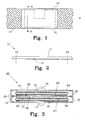
- Figure 1 shows a non-metal carrier 10 made from a conductive material, such as a woven carbon fibre cloth, or non-conductive material, such as a polymer preferably made from polypropylene, having a predetermined width w and an arbitrary length.
- the carrier 10 is preferably arranged in a roll, see figure 4 .
- a compressed powder 11 is arranged on the non-metal carrier 10 and a desired shape of the electrode 13 is outlined by the dashed line 12. The compressed powder 11 and the carrier 10 are cut along line 12 to form the electrode 13.
- the positive active material in a NiMH battery manufactured according to the invention is preferably made from spherical nickel hydroxide (supplied by OMG, Finland) ; Nickel 210 fiber (supplied by INCO, USA); and Powdered Cobalt (obtainable from various suppliers).
- the negative material is preferably made with Metal Hydride (supplied by Treibacher, Austria) ; and Nickel 255 fiber (supplied by INCO, USA). There are numerous suppliers of all these materials, particularly in Japan and China, where the majority of Nickel Metal Hydride cells presently are manufactured.
- the nickel fibers INCO 210 and 255 serve as the conductive additives and make contact with the conductive biplate, conducting current from the active material directly to the conductive biplate.
- Figure 2 shows a cross-sectional view along A-A in figure 1 , where lines 12 indicate the desired shape of the finished electrode 13.
- the compressed powder 11 is mainly situated on top of the carrier 10. During compression of the active powder, some amount of the active powder may migrate to the other side of the carrier 10 depending on the structure of the carrier 10. If a random structure of polymer is applied, almost nothing will migrate through the carrier 10, but if a grid structure of polymer is used more active material will end up on the other side of the carrier 10, i.e. the carrier 10 could be placed in the center of the electrode 13.
- the reference numeral 13 indicates the electrode after cutting along lines 12.
- FIG. 3 shows a bipolar battery 15, preferably a NiMH battery, having a positive 16 and a negative 17 end terminal.
- a biplate assembly 20 is provided comprising a biplate 21, a positive electrode 27 of positive active material 22 arranged on a non-metal carrier 10, and a negative electrode 28 of negative active material 23 arranged on a non-metal carrier 10.
- the active materials 22, 23 are powder pressed onto the carrier 10.
- the bipolar battery contains in this example only one biplate assembly, but several biplate assemblies may naturally be included in a bipolar battery.
- the positive end terminal 16 has a positive electrode 27 and the negative end terminal 17 has a negative electrode 28.
- a separator 24 containing electrolyte is arranged between adjacent positive 27 and negative 28 electrodes.
- the non-metal carrier 10 of each electrode 27, 28 is preferably arranged towards the separator 24, as indicated in figure 3 .
- the surface of the sides 25 and 26, respectively, of the biplate 21 is preferably a bit rough to keep the electrodes in place during manufacture and operations. The surface of the end terminals may naturally also be rough for the same purpose.
- a housing 29 provides a sealing of the battery 15. The details of the construction of the battery provides a bipolar battery 15 with an electrolyte seal, the hydrophobic barrier 18, for each cell and a gas seal, the housing 29, for all cells in the battery.
- the electrodes 27 and 28 including a non-metal carrier 10, preferably a non-conductive carrier, according to the invention may naturally be used in any type of bipolar battery having separately made electrodes.
- Figure 4 shows an apparatus 30 for manufacturing an electrode having a non-metal carrier 10 according to the invention.
- a roll 31 with a tensioning device, such as a spring supplies a non-conductive carrier 10 to the apparatus and two rollers 32 and 33 rotate to pull the carrier 10 under tension in to the apparatus.
- a distributor 37 arranges active powder 38 on the carrier 10, and a spreader 39 levels the active powder 38 before the powder is compressed between the rollers 32 and 33.
- the powder 38 may either be arranged continuously on the carrier 10, or in a discrete fashion as shown in figure 4 .
- a compressed powder 11 is thus arranged on the carrier 10 and a cutter 34 forms the electrode into the desired shape.
- Scrap material after cutting is ground and recycled, which is possible due to the use of the non-metal carrier.
- An agitator 36 is provided within the powder container and provides powder with a uniform density to the distributor 37, which collects powder in a uniform volume and distributes it to the carrier 10. This process is more described in connection with figure 5 below.
- the powder container is provided with a level sensor 40, and a level control unit 41 opens a valve 42 to add more powder from a powder supply 43 when the level in the powder container is too low.
- a sensor 44 is also provided at the spreader 39 to monitor the amount of powder arranged on the carrier 10 prior to leveling and pressing.
- the sensor 44 sends a signal back to the distributor, via a control unit 45, to alter the rotation speed and thereby change the amount of powder distributed to the non-metal carrier 10.
- Figure 5 shows a detailed view of the mechanism distributing the active powder 50 onto the carrier 10.
- the purpose of the agitator 36 is to provide a uniform density powder to the distributor 37 and prevent "bridges", i.e. voids, that could occur in the powder supply container.
- the distributor 37 is provided with grooves 51 having a uniform volume, which are filled with the powder 50 during rotation, and the active powder is thereafter distributed to the carrier 10 in a suitable amount.
- the preferred method uses the carrier 10 as a film to convey the loose powder into the rolling mill for compaction, and the process is conducted at room ambient conditions.
- the time, or rate of production is most dependent upon the powder spreading mechanism and the roll diameters.
- An acceptable production rate require 4 inch (approx. 10 cm) diameter rolls that have a preferred speed of 1.5 to 3 meters per minute.
- a lower production rate would be feasible, but not economical.
- Maximum speed is dependent on the equipment including material handling to cut the strip to electrode size and convey them to subsequent steps, such as assembling steps.
- the physical dimensions of the finished product depend on the equipment specified. For heat transfer considerations at the final battery level, the equipment is limited to manufacture electrodes 6 inches (approx. 15 cm) wide. The thickness of the electrodes is in the range of 0.002 to 0.050 inches (approx. 0.05 to 1.3 mm), with a preferred range of 0.010 to 0.035 inches (approx. 0.25 to 0.90 mm).
- the final electrodes normally have the shape of a rectangle, but other shapes are naturally possible.
- the electrode thickness depends upon the ratio of power required to energy required. Higher power applications require thinner electrodes.
- the non-conductive carrier must transport the powder into the rolls without the material totally sieving through it.
- the final location of the carrier material can be anywhere within the electrode, but it is preferable to be closest to the side of the electrode that is placed in contact with the separator. The material should allow sufficient particles to penetrate so the compressive forces compact the powder, and do not form the non-conductive carrier into a film.
Landscapes
- Engineering & Computer Science (AREA)
- Chemical & Material Sciences (AREA)
- Manufacturing & Machinery (AREA)
- Chemical Kinetics & Catalysis (AREA)
- Electrochemistry (AREA)
- General Chemical & Material Sciences (AREA)
- Materials Engineering (AREA)
- Battery Electrode And Active Subsutance (AREA)
- Cell Electrode Carriers And Collectors (AREA)
Claims (15)
- Électrode (13) destinée à un ensemble biplaque dans une batterie bipolaire, ladite électrode comprenant .- un matériau actif constitué d'une poudre active (11), et- un support non métallique (10),
dans laquelle ladite poudre active (11) est comprimée sur ledit support non métallique pour former ladite électrode,
dans laquelle ledit support non métallique (10) est un support non conducteur, et
dans laquelle ledit support non métallique (10) est constitué d'un matériau polymère et a une structure aléatoire de fibres de polymère. - Électrode selon la revendication 1, dans laquelle la poudre comprimée (11) est principalement disposée sur un côté du support non métallique (10).
- Électrode selon la revendication 1 ou 2, l'électrode ayant une épaisseur comprise entre 0,05 et 1,3 mm.
- Électrode selon la revendication 3, l'électrode ayant une épaisseur préférée comprise entre 0,25 et 0,90 mm.
- Ensemble biplaque (20) destiné à une batterie bipolaire, ledit ensemble biplaque comprenant :- une biplaque (21),- une électrode positive (27) d'un matériau actif positif (22), et- une électrode négative (28) d'un matériau actif négatif (23), opposée audit matériau actif positif (22),
dans lequel chaque électrode (27, 28) comprend en outre un support non métallique (10), et où les matériaux actifs sont prévus sous la forme de poudre active comprimée sur le support,
dans lequel ledit support non métallique (10) est un support non conducteur,
dans lequel ledit support non métallique (10) est constitué d'un matériau polymère et a une structure aléatoire de fibres de polymère, et
dans lequel le support non métallique (10) est sans contact avec la biplaque (21). - Ensemble biplaque selon la revendication 5, cet ensemble biplaque (20) comprenant en outre un séparateur (24) doté d'un électrolyte, ledit séparateur étant en contact avec le support non métallique (10).
- Procédé de fabrication d'une électrode (13) pour un ensemble biplaque dans une batterie bipolaire, ledit procédé comprenant les étapes suivantes :- prendre un matériau actif constitué d'une poudre active ;- prendre un support non métallique (10) ; et- comprimer ladite poudre active sur ledit support non métallique pour former ladite électrode,
dans lequel ledit support non métallique (10) est choisi pour être un support non conducteur, et
dans lequel ledit support non métallique (10) est constitué d'un matériau polymère présentant une structure aléatoire de fibres de polymère. - Procédé selon la revendication 7, ce procédé comprenant en outre l'étape de formation d'une forme (12) de l'électrode (13).
- Procédé selon la revendication 8, dans lequel l'étape de formation de l'électrode comprend le fait de couper le matériau actif et le support non métallique à l'aide d'un cutter (34).
- Procédé selon l'une quelconque des revendications 7 à 9, dans lequel le matériau actif (38) n'est appliqué que d'un côté du support non métallique (10).
- Procédé selon l'une quelconque des revendications 7 à 10, dans lequel le matériau actif (38) est disposé en continu sur le support non métallique (10).
- Procédé selon l'une quelconque des revendications 7 à 10, dans lequel le matériau actif (38) est disposé de manière discrète sur le support non métallique (10).
- Procédé selon l'une quelconque des revendications 7 à 12, dans lequel l'étape de compression du matériau actif comprend l'emploi d'une force de compression sur une quantité appropriée de matériau actif, afin d'obtenir une électrode dont l'épaisseur est comprise entre 0,05 et 1,3 mm.
- Procédé selon la revendication 13, dans lequel on choisit l'électrode pour que son épaisseur soit comprise entre 0,25 et 0,90 mm.
- Batterie bipolaire (15), caractérisée en ce que ladite batterie bipolaire comprend au moins une électrode (27, 28) selon l'une quelconque des revendications 1 à 4.
Applications Claiming Priority (5)
| Application Number | Priority Date | Filing Date | Title |
|---|---|---|---|
| SE0203307 | 2002-11-08 | ||
| SE0203307A SE525367C2 (sv) | 2002-11-08 | 2002-11-08 | En elektrod och en metod för tillverkning av en elektrod |
| US10/434,167 US20040091784A1 (en) | 2002-11-08 | 2003-05-09 | Electrode, a method for manufacturing an electrode and an apparatus for manufacturing an electrode |
| US434167 | 2003-05-09 | ||
| PCT/SE2003/001722 WO2004042846A1 (fr) | 2002-11-08 | 2003-11-07 | Electrode, procede de fabrication d'une electrode et batterie bipolaire |
Publications (2)
| Publication Number | Publication Date |
|---|---|
| EP1559153A1 EP1559153A1 (fr) | 2005-08-03 |
| EP1559153B1 true EP1559153B1 (fr) | 2014-06-04 |
Family
ID=32314178
Family Applications (2)
| Application Number | Title | Priority Date | Filing Date |
|---|---|---|---|
| EP03810729.8A Expired - Lifetime EP1559153B1 (fr) | 2002-11-08 | 2003-11-07 | Electrode, procede de fabrication d'une electrode et batterie bipolaire |
| EP03770206A Withdrawn EP1559152A1 (fr) | 2002-11-08 | 2003-11-07 | Appareil servant a fabriquer une electrode |
Family Applications After (1)
| Application Number | Title | Priority Date | Filing Date |
|---|---|---|---|
| EP03770206A Withdrawn EP1559152A1 (fr) | 2002-11-08 | 2003-11-07 | Appareil servant a fabriquer une electrode |
Country Status (6)
| Country | Link |
|---|---|
| EP (2) | EP1559153B1 (fr) |
| JP (1) | JP4555222B2 (fr) |
| AU (2) | AU2003278672A1 (fr) |
| CA (1) | CA2500124A1 (fr) |
| MX (1) | MXPA05003727A (fr) |
| WO (2) | WO2004042847A1 (fr) |
Families Citing this family (5)
| Publication number | Priority date | Publication date | Assignee | Title |
|---|---|---|---|---|
| US9894955B2 (en) | 2002-07-31 | 2018-02-20 | Dynasty Footwear, Ltd. | Shoe having individual particles bonded to its bottom surface |
| SE530190C2 (sv) | 2006-01-17 | 2008-03-25 | Nilar Int Ab | Ett batteristapelarrangemang |
| US7846493B1 (en) | 2006-10-02 | 2010-12-07 | Dynasty Foorwear, Ltd. | Spraying of fibers from a container that includes an agitator |
| US11284676B2 (en) | 2012-06-13 | 2022-03-29 | John C. S. Koo | Shoe having a partially coated upper |
| US10143267B1 (en) | 2013-12-31 | 2018-12-04 | Dynasty Footwear, Ltd. | Shoe bottom surface having attached particles |
Citations (5)
| Publication number | Priority date | Publication date | Assignee | Title |
|---|---|---|---|---|
| US3560262A (en) * | 1967-12-08 | 1971-02-02 | Sony Corp | Electrode with a non-woven fabric base and electroplated coatings of nickel |
| US4161569A (en) * | 1977-03-12 | 1979-07-17 | Rheinisch-Westfalisches Elektrizitatswerk Aktiengesellschaft | Composite electrode for storage batteries, accumulators and the like |
| WO1996012313A1 (fr) * | 1994-10-12 | 1996-04-25 | Bipolar Technologies Corporation | Cellules pour batteries bipolaires, batteries et procedes |
| US5552243A (en) * | 1993-10-08 | 1996-09-03 | Electro Energy, Inc. | Bipolar electrochemical battery of stacked wafer cells |
| US5993494A (en) * | 1997-07-25 | 1999-11-30 | Gnb Technologies, Inc. | Method of manufacturing modular components for a bipolar battery and the resulting bipolar battery |
Family Cites Families (11)
| Publication number | Priority date | Publication date | Assignee | Title |
|---|---|---|---|---|
| DE1496355A1 (de) * | 1962-05-18 | 1969-05-14 | Yardney International Corp | Separator fuer elektrische Batterien |
| DE3117660C2 (de) * | 1981-05-05 | 1984-08-02 | Dieter H. Dr. 3400 Göttingen Buss | Wiederaufladbare elektrochemische Zelle |
| DE3609646A1 (de) * | 1986-03-21 | 1987-09-24 | Hoechst Ag | Flexible, elektrisch leitfaehige verbundkoerper, verfahren zu ihrer herstellung und ihre verwendung |
| EP0350487B1 (fr) * | 1987-03-13 | 1993-07-07 | Ppg Industries, Inc. | Separateur pour accumulateurs a recombinaison gazeuse |
| JP2851681B2 (ja) * | 1990-04-11 | 1999-01-27 | エナージー・コンバーシヨン・デバイセス・インコーポレーテツド | 微粉砕した水素吸蔵合金材料からなる負極の連続的製造方法 |
| JPH06325756A (ja) * | 1993-05-14 | 1994-11-25 | Aisin Seiki Co Ltd | 鉛電池用電極の製造方法 |
| JP3457858B2 (ja) * | 1997-09-26 | 2003-10-20 | 東芝電池株式会社 | リチウムポリマー電池用電極要素の製造装置 |
| JP3526812B2 (ja) * | 2000-05-26 | 2004-05-17 | Fdk株式会社 | 電極スリッタ装置 |
| JP2001351616A (ja) * | 2000-06-05 | 2001-12-21 | Toyota Motor Corp | 電極の製造方法 |
| JP2002093407A (ja) * | 2000-09-12 | 2002-03-29 | Toshiba Battery Co Ltd | 電池用電極シートの製造方法、製造装置 |
| JP2002110146A (ja) * | 2000-10-03 | 2002-04-12 | Mekatekku Kk | 回転刃を用いた電極部材の製造方法及び電池の製造方法 |
-
2003
- 2003-11-07 MX MXPA05003727A patent/MXPA05003727A/es active IP Right Grant
- 2003-11-07 AU AU2003278672A patent/AU2003278672A1/en not_active Abandoned
- 2003-11-07 CA CA002500124A patent/CA2500124A1/fr not_active Abandoned
- 2003-11-07 JP JP2005502167A patent/JP4555222B2/ja not_active Expired - Lifetime
- 2003-11-07 WO PCT/SE2003/001723 patent/WO2004042847A1/fr not_active Ceased
- 2003-11-07 AU AU2003276795A patent/AU2003276795A1/en not_active Abandoned
- 2003-11-07 WO PCT/SE2003/001722 patent/WO2004042846A1/fr not_active Ceased
- 2003-11-07 EP EP03810729.8A patent/EP1559153B1/fr not_active Expired - Lifetime
- 2003-11-07 EP EP03770206A patent/EP1559152A1/fr not_active Withdrawn
Patent Citations (5)
| Publication number | Priority date | Publication date | Assignee | Title |
|---|---|---|---|---|
| US3560262A (en) * | 1967-12-08 | 1971-02-02 | Sony Corp | Electrode with a non-woven fabric base and electroplated coatings of nickel |
| US4161569A (en) * | 1977-03-12 | 1979-07-17 | Rheinisch-Westfalisches Elektrizitatswerk Aktiengesellschaft | Composite electrode for storage batteries, accumulators and the like |
| US5552243A (en) * | 1993-10-08 | 1996-09-03 | Electro Energy, Inc. | Bipolar electrochemical battery of stacked wafer cells |
| WO1996012313A1 (fr) * | 1994-10-12 | 1996-04-25 | Bipolar Technologies Corporation | Cellules pour batteries bipolaires, batteries et procedes |
| US5993494A (en) * | 1997-07-25 | 1999-11-30 | Gnb Technologies, Inc. | Method of manufacturing modular components for a bipolar battery and the resulting bipolar battery |
Also Published As
| Publication number | Publication date |
|---|---|
| WO2004042846A1 (fr) | 2004-05-21 |
| EP1559152A1 (fr) | 2005-08-03 |
| JP4555222B2 (ja) | 2010-09-29 |
| MXPA05003727A (es) | 2005-09-30 |
| JP2006505917A (ja) | 2006-02-16 |
| AU2003278672A1 (en) | 2004-06-07 |
| WO2004042847A1 (fr) | 2004-05-21 |
| AU2003276795A1 (en) | 2004-06-07 |
| EP1559153A1 (fr) | 2005-08-03 |
| CA2500124A1 (fr) | 2004-05-21 |
Similar Documents
| Publication | Publication Date | Title |
|---|---|---|
| US9548488B2 (en) | Method for manufacturing electrode | |
| JP5889826B2 (ja) | 充電式電池(2次電池)用シリコン陽極 | |
| KR101243604B1 (ko) | 결합 실리콘 섬유 | |
| US8310810B2 (en) | Electric double-layer capacitor including holes penetrating a negative electrode current collector and method of producing same | |
| US20080268341A1 (en) | High power batteries and electrochemical cells and methods of making same | |
| JP2010527128A6 (ja) | 充電式電池(2次電池)用シリコン陽極 | |
| EP0867248B1 (fr) | Procédé de préparation d'une feuille poreuse métallique | |
| JPH11154517A (ja) | 二次電池用金属多孔体及びその製造方法 | |
| US20080107958A1 (en) | Chargeable Electrochemical Cell | |
| AU683396B2 (en) | Method of making a battery plate | |
| EP1559153B1 (fr) | Electrode, procede de fabrication d'une electrode et batterie bipolaire | |
| US3432351A (en) | Process for producing electrodes for galvanic batteries | |
| JPH08321303A (ja) | アルカリ二次電池用の電極 | |
| EP1215741B1 (fr) | Procédé de fabrication d'une plaque d'électrode positive | |
| CN216236058U (zh) | 一种球形石墨负极加工用包覆装置 | |
| JP5294809B2 (ja) | ニッケル焼結基板の製造方法 | |
| KR102167913B1 (ko) | 전극 와이어들을 포함하는 이차전지용 전극 및 이의 제조 방법 | |
| EP0742600A1 (fr) | Electrodes pour batterie et méthode de fabrication | |
| JPH09259873A (ja) | 二次電池用電極とその製造方法、ならびに、その製造に用いるフッ素樹脂の塗布装置 | |
| CN119517938A (zh) | 正极片及电芯 | |
| EP1449948B1 (fr) | Article non-tisse en fibre de carbone se presentant sous la forme d'une bande et son procede de realisation | |
| CN114709359A (zh) | 一种电池极片及其连续加工方法 | |
| CN119481341A (zh) | 卷芯及电池 | |
| JPS63237367A (ja) | 固体電解質を含む電気化学素子部材の製造方法 | |
| Pathanjali | A High Capacity Nickel Cadmium Cell Using Composite Fiber Electrode Technology |
Legal Events
| Date | Code | Title | Description |
|---|---|---|---|
| PUAI | Public reference made under article 153(3) epc to a published international application that has entered the european phase |
Free format text: ORIGINAL CODE: 0009012 |
|
| 17P | Request for examination filed |
Effective date: 20050317 |
|
| AK | Designated contracting states |
Kind code of ref document: A1 Designated state(s): AT BE BG CH CY CZ DE DK EE ES FI FR GB GR HU IE IT LI LU MC NL PT RO SE SI SK TR |
|
| AX | Request for extension of the european patent |
Extension state: AL LT LV MK |
|
| DAX | Request for extension of the european patent (deleted) | ||
| 17Q | First examination report despatched |
Effective date: 20051007 |
|
| GRAP | Despatch of communication of intention to grant a patent |
Free format text: ORIGINAL CODE: EPIDOSNIGR1 |
|
| INTG | Intention to grant announced |
Effective date: 20140107 |
|
| GRAS | Grant fee paid |
Free format text: ORIGINAL CODE: EPIDOSNIGR3 |
|
| GRAA | (expected) grant |
Free format text: ORIGINAL CODE: 0009210 |
|
| AK | Designated contracting states |
Kind code of ref document: B1 Designated state(s): AT BE BG CH CY CZ DE DK EE ES FI FR GB GR HU IE IT LI LU MC NL PT RO SE SI SK TR |
|
| REG | Reference to a national code |
Ref country code: GB Ref legal event code: FG4D |
|
| REG | Reference to a national code |
Ref country code: CH Ref legal event code: EP |
|
| REG | Reference to a national code |
Ref country code: AT Ref legal event code: REF Ref document number: 671531 Country of ref document: AT Kind code of ref document: T Effective date: 20140615 |
|
| REG | Reference to a national code |
Ref country code: IE Ref legal event code: FG4D |
|
| REG | Reference to a national code |
Ref country code: DE Ref legal event code: R096 Ref document number: 60346298 Country of ref document: DE Effective date: 20140717 |
|
| REG | Reference to a national code |
Ref country code: SE Ref legal event code: TRGR |
|
| REG | Reference to a national code |
Ref country code: CH Ref legal event code: NV Representative=s name: R. A. EGLI AND CO. PATENTANWAELTE, CH |
|
| REG | Reference to a national code |
Ref country code: AT Ref legal event code: MK05 Ref document number: 671531 Country of ref document: AT Kind code of ref document: T Effective date: 20140604 |
|
| REG | Reference to a national code |
Ref country code: NL Ref legal event code: VDEP Effective date: 20140604 |
|
| PG25 | Lapsed in a contracting state [announced via postgrant information from national office to epo] |
Ref country code: FI Free format text: LAPSE BECAUSE OF FAILURE TO SUBMIT A TRANSLATION OF THE DESCRIPTION OR TO PAY THE FEE WITHIN THE PRESCRIBED TIME-LIMIT Effective date: 20140604 Ref country code: CY Free format text: LAPSE BECAUSE OF FAILURE TO SUBMIT A TRANSLATION OF THE DESCRIPTION OR TO PAY THE FEE WITHIN THE PRESCRIBED TIME-LIMIT Effective date: 20140604 Ref country code: GR Free format text: LAPSE BECAUSE OF FAILURE TO SUBMIT A TRANSLATION OF THE DESCRIPTION OR TO PAY THE FEE WITHIN THE PRESCRIBED TIME-LIMIT Effective date: 20140905 |
|
| PG25 | Lapsed in a contracting state [announced via postgrant information from national office to epo] |
Ref country code: AT Free format text: LAPSE BECAUSE OF FAILURE TO SUBMIT A TRANSLATION OF THE DESCRIPTION OR TO PAY THE FEE WITHIN THE PRESCRIBED TIME-LIMIT Effective date: 20140604 |
|
| PG25 | Lapsed in a contracting state [announced via postgrant information from national office to epo] |
Ref country code: ES Free format text: LAPSE BECAUSE OF FAILURE TO SUBMIT A TRANSLATION OF THE DESCRIPTION OR TO PAY THE FEE WITHIN THE PRESCRIBED TIME-LIMIT Effective date: 20140604 Ref country code: PT Free format text: LAPSE BECAUSE OF FAILURE TO SUBMIT A TRANSLATION OF THE DESCRIPTION OR TO PAY THE FEE WITHIN THE PRESCRIBED TIME-LIMIT Effective date: 20141006 Ref country code: RO Free format text: LAPSE BECAUSE OF FAILURE TO SUBMIT A TRANSLATION OF THE DESCRIPTION OR TO PAY THE FEE WITHIN THE PRESCRIBED TIME-LIMIT Effective date: 20140604 Ref country code: SK Free format text: LAPSE BECAUSE OF FAILURE TO SUBMIT A TRANSLATION OF THE DESCRIPTION OR TO PAY THE FEE WITHIN THE PRESCRIBED TIME-LIMIT Effective date: 20140604 Ref country code: EE Free format text: LAPSE BECAUSE OF FAILURE TO SUBMIT A TRANSLATION OF THE DESCRIPTION OR TO PAY THE FEE WITHIN THE PRESCRIBED TIME-LIMIT Effective date: 20140604 Ref country code: CZ Free format text: LAPSE BECAUSE OF FAILURE TO SUBMIT A TRANSLATION OF THE DESCRIPTION OR TO PAY THE FEE WITHIN THE PRESCRIBED TIME-LIMIT Effective date: 20140604 |
|
| PG25 | Lapsed in a contracting state [announced via postgrant information from national office to epo] |
Ref country code: NL Free format text: LAPSE BECAUSE OF FAILURE TO SUBMIT A TRANSLATION OF THE DESCRIPTION OR TO PAY THE FEE WITHIN THE PRESCRIBED TIME-LIMIT Effective date: 20140604 |
|
| REG | Reference to a national code |
Ref country code: DE Ref legal event code: R097 Ref document number: 60346298 Country of ref document: DE |
|
| PLBE | No opposition filed within time limit |
Free format text: ORIGINAL CODE: 0009261 |
|
| STAA | Information on the status of an ep patent application or granted ep patent |
Free format text: STATUS: NO OPPOSITION FILED WITHIN TIME LIMIT |
|
| PG25 | Lapsed in a contracting state [announced via postgrant information from national office to epo] |
Ref country code: IT Free format text: LAPSE BECAUSE OF FAILURE TO SUBMIT A TRANSLATION OF THE DESCRIPTION OR TO PAY THE FEE WITHIN THE PRESCRIBED TIME-LIMIT Effective date: 20140604 Ref country code: DK Free format text: LAPSE BECAUSE OF FAILURE TO SUBMIT A TRANSLATION OF THE DESCRIPTION OR TO PAY THE FEE WITHIN THE PRESCRIBED TIME-LIMIT Effective date: 20140604 |
|
| 26N | No opposition filed |
Effective date: 20150305 |
|
| REG | Reference to a national code |
Ref country code: DE Ref legal event code: R097 Ref document number: 60346298 Country of ref document: DE Effective date: 20150305 |
|
| PG25 | Lapsed in a contracting state [announced via postgrant information from national office to epo] |
Ref country code: LU Free format text: LAPSE BECAUSE OF FAILURE TO SUBMIT A TRANSLATION OF THE DESCRIPTION OR TO PAY THE FEE WITHIN THE PRESCRIBED TIME-LIMIT Effective date: 20141107 Ref country code: BE Free format text: LAPSE BECAUSE OF FAILURE TO SUBMIT A TRANSLATION OF THE DESCRIPTION OR TO PAY THE FEE WITHIN THE PRESCRIBED TIME-LIMIT Effective date: 20140604 Ref country code: MC Free format text: LAPSE BECAUSE OF FAILURE TO SUBMIT A TRANSLATION OF THE DESCRIPTION OR TO PAY THE FEE WITHIN THE PRESCRIBED TIME-LIMIT Effective date: 20140604 |
|
| PG25 | Lapsed in a contracting state [announced via postgrant information from national office to epo] |
Ref country code: SI Free format text: LAPSE BECAUSE OF FAILURE TO SUBMIT A TRANSLATION OF THE DESCRIPTION OR TO PAY THE FEE WITHIN THE PRESCRIBED TIME-LIMIT Effective date: 20140604 |
|
| REG | Reference to a national code |
Ref country code: IE Ref legal event code: MM4A |
|
| PG25 | Lapsed in a contracting state [announced via postgrant information from national office to epo] |
Ref country code: IE Free format text: LAPSE BECAUSE OF NON-PAYMENT OF DUE FEES Effective date: 20141107 |
|
| REG | Reference to a national code |
Ref country code: FR Ref legal event code: PLFP Year of fee payment: 13 |
|
| PG25 | Lapsed in a contracting state [announced via postgrant information from national office to epo] |
Ref country code: BG Free format text: LAPSE BECAUSE OF FAILURE TO SUBMIT A TRANSLATION OF THE DESCRIPTION OR TO PAY THE FEE WITHIN THE PRESCRIBED TIME-LIMIT Effective date: 20140604 |
|
| PG25 | Lapsed in a contracting state [announced via postgrant information from national office to epo] |
Ref country code: TR Free format text: LAPSE BECAUSE OF FAILURE TO SUBMIT A TRANSLATION OF THE DESCRIPTION OR TO PAY THE FEE WITHIN THE PRESCRIBED TIME-LIMIT Effective date: 20140604 Ref country code: HU Free format text: LAPSE BECAUSE OF FAILURE TO SUBMIT A TRANSLATION OF THE DESCRIPTION OR TO PAY THE FEE WITHIN THE PRESCRIBED TIME-LIMIT; INVALID AB INITIO Effective date: 20031107 |
|
| REG | Reference to a national code |
Ref country code: FR Ref legal event code: PLFP Year of fee payment: 14 |
|
| REG | Reference to a national code |
Ref country code: DE Ref legal event code: R082 Ref document number: 60346298 Country of ref document: DE |
|
| REG | Reference to a national code |
Ref country code: FR Ref legal event code: PLFP Year of fee payment: 15 |
|
| PGFP | Annual fee paid to national office [announced via postgrant information from national office to epo] |
Ref country code: CH Payment date: 20191118 Year of fee payment: 17 |
|
| REG | Reference to a national code |
Ref country code: DE Ref legal event code: R079 Ref document number: 60346298 Country of ref document: DE Free format text: PREVIOUS MAIN CLASS: H01M0002160000 Ipc: H01M0050409000 |
|
| REG | Reference to a national code |
Ref country code: CH Ref legal event code: PL |
|
| PG25 | Lapsed in a contracting state [announced via postgrant information from national office to epo] |
Ref country code: CH Free format text: LAPSE BECAUSE OF NON-PAYMENT OF DUE FEES Effective date: 20201130 Ref country code: LI Free format text: LAPSE BECAUSE OF NON-PAYMENT OF DUE FEES Effective date: 20201130 |
|
| PGFP | Annual fee paid to national office [announced via postgrant information from national office to epo] |
Ref country code: FR Payment date: 20221010 Year of fee payment: 20 |
|
| PGFP | Annual fee paid to national office [announced via postgrant information from national office to epo] |
Ref country code: SE Payment date: 20221004 Year of fee payment: 20 Ref country code: GB Payment date: 20221003 Year of fee payment: 20 Ref country code: DE Payment date: 20221004 Year of fee payment: 20 |
|
| REG | Reference to a national code |
Ref country code: DE Ref legal event code: R071 Ref document number: 60346298 Country of ref document: DE |
|
| REG | Reference to a national code |
Ref country code: GB Ref legal event code: PE20 Expiry date: 20231106 |
|
| REG | Reference to a national code |
Ref country code: SE Ref legal event code: EUG |
|
| PG25 | Lapsed in a contracting state [announced via postgrant information from national office to epo] |
Ref country code: GB Free format text: LAPSE BECAUSE OF EXPIRATION OF PROTECTION Effective date: 20231106 |
|
| PG25 | Lapsed in a contracting state [announced via postgrant information from national office to epo] |
Ref country code: GB Free format text: LAPSE BECAUSE OF EXPIRATION OF PROTECTION Effective date: 20231106 |