EP1559078B1 - Geldscheinverarbeitungsvorrichtung und verfahren zum übertragen von codeinformationen - Google Patents
Geldscheinverarbeitungsvorrichtung und verfahren zum übertragen von codeinformationen Download PDFInfo
- Publication number
- EP1559078B1 EP1559078B1 EP03810623A EP03810623A EP1559078B1 EP 1559078 B1 EP1559078 B1 EP 1559078B1 EP 03810623 A EP03810623 A EP 03810623A EP 03810623 A EP03810623 A EP 03810623A EP 1559078 B1 EP1559078 B1 EP 1559078B1
- Authority
- EP
- European Patent Office
- Prior art keywords
- bill
- information
- code
- handling apparatus
- control circuit
- Prior art date
- Legal status (The legal status is an assumption and is not a legal conclusion. Google has not performed a legal analysis and makes no representation as to the accuracy of the status listed.)
- Expired - Lifetime
Links
Images


Classifications
-
- G—PHYSICS
- G07—CHECKING-DEVICES
- G07D—HANDLING OF COINS OR VALUABLE PAPERS, e.g. TESTING, SORTING BY DENOMINATIONS, COUNTING, DISPENSING, CHANGING OR DEPOSITING
- G07D7/00—Testing specially adapted to determine the identity or genuineness of valuable papers or for segregating those which are unacceptable, e.g. banknotes that are alien to a currency
- G07D7/01—Testing electronic circuits therein
-
- G—PHYSICS
- G06—COMPUTING OR CALCULATING; COUNTING
- G06Q—INFORMATION AND COMMUNICATION TECHNOLOGY [ICT] SPECIALLY ADAPTED FOR ADMINISTRATIVE, COMMERCIAL, FINANCIAL, MANAGERIAL OR SUPERVISORY PURPOSES; SYSTEMS OR METHODS SPECIALLY ADAPTED FOR ADMINISTRATIVE, COMMERCIAL, FINANCIAL, MANAGERIAL OR SUPERVISORY PURPOSES, NOT OTHERWISE PROVIDED FOR
- G06Q20/00—Payment architectures, schemes or protocols
- G06Q20/30—Payment architectures, schemes or protocols characterised by the use of specific devices or networks
- G06Q20/34—Payment architectures, schemes or protocols characterised by the use of specific devices or networks using cards, e.g. integrated circuit [IC] cards or magnetic cards
- G06Q20/341—Active cards, i.e. cards including their own processing means, e.g. including an IC or chip
-
- G—PHYSICS
- G06—COMPUTING OR CALCULATING; COUNTING
- G06Q—INFORMATION AND COMMUNICATION TECHNOLOGY [ICT] SPECIALLY ADAPTED FOR ADMINISTRATIVE, COMMERCIAL, FINANCIAL, MANAGERIAL OR SUPERVISORY PURPOSES; SYSTEMS OR METHODS SPECIALLY ADAPTED FOR ADMINISTRATIVE, COMMERCIAL, FINANCIAL, MANAGERIAL OR SUPERVISORY PURPOSES, NOT OTHERWISE PROVIDED FOR
- G06Q20/00—Payment architectures, schemes or protocols
- G06Q20/30—Payment architectures, schemes or protocols characterised by the use of specific devices or networks
- G06Q20/34—Payment architectures, schemes or protocols characterised by the use of specific devices or networks using cards, e.g. integrated circuit [IC] cards or magnetic cards
- G06Q20/355—Personalisation of cards for use
- G06Q20/3552—Downloading or loading of personalisation data
-
- G—PHYSICS
- G06—COMPUTING OR CALCULATING; COUNTING
- G06Q—INFORMATION AND COMMUNICATION TECHNOLOGY [ICT] SPECIALLY ADAPTED FOR ADMINISTRATIVE, COMMERCIAL, FINANCIAL, MANAGERIAL OR SUPERVISORY PURPOSES; SYSTEMS OR METHODS SPECIALLY ADAPTED FOR ADMINISTRATIVE, COMMERCIAL, FINANCIAL, MANAGERIAL OR SUPERVISORY PURPOSES, NOT OTHERWISE PROVIDED FOR
- G06Q20/00—Payment architectures, schemes or protocols
- G06Q20/38—Payment protocols; Details thereof
- G06Q20/40—Authorisation, e.g. identification of payer or payee, verification of customer or shop credentials; Review and approval of payers, e.g. check credit lines or negative lists
- G06Q20/409—Device specific authentication in transaction processing
- G06Q20/4097—Device specific authentication in transaction processing using mutual authentication between devices and transaction partners
-
- G—PHYSICS
- G07—CHECKING-DEVICES
- G07D—HANDLING OF COINS OR VALUABLE PAPERS, e.g. TESTING, SORTING BY DENOMINATIONS, COUNTING, DISPENSING, CHANGING OR DEPOSITING
- G07D11/00—Devices accepting coins; Devices accepting, dispensing, sorting or counting valuable papers
- G07D11/10—Mechanical details
- G07D11/12—Containers for valuable papers
-
- G—PHYSICS
- G07—CHECKING-DEVICES
- G07D—HANDLING OF COINS OR VALUABLE PAPERS, e.g. TESTING, SORTING BY DENOMINATIONS, COUNTING, DISPENSING, CHANGING OR DEPOSITING
- G07D11/00—Devices accepting coins; Devices accepting, dispensing, sorting or counting valuable papers
- G07D11/20—Controlling or monitoring the operation of devices; Data handling
- G07D11/30—Tracking or tracing valuable papers or cassettes
-
- G—PHYSICS
- G07—CHECKING-DEVICES
- G07D—HANDLING OF COINS OR VALUABLE PAPERS, e.g. TESTING, SORTING BY DENOMINATIONS, COUNTING, DISPENSING, CHANGING OR DEPOSITING
- G07D11/00—Devices accepting coins; Devices accepting, dispensing, sorting or counting valuable papers
- G07D11/20—Controlling or monitoring the operation of devices; Data handling
- G07D11/32—Record keeping
- G07D11/34—Monitoring the contents of devices, e.g. the number of stored valuable papers
-
- G—PHYSICS
- G07—CHECKING-DEVICES
- G07D—HANDLING OF COINS OR VALUABLE PAPERS, e.g. TESTING, SORTING BY DENOMINATIONS, COUNTING, DISPENSING, CHANGING OR DEPOSITING
- G07D7/00—Testing specially adapted to determine the identity or genuineness of valuable papers or for segregating those which are unacceptable, e.g. banknotes that are alien to a currency
- G07D7/004—Testing specially adapted to determine the identity or genuineness of valuable papers or for segregating those which are unacceptable, e.g. banknotes that are alien to a currency using digital security elements, e.g. information coded on a magnetic thread or strip
-
- G—PHYSICS
- G07—CHECKING-DEVICES
- G07D—HANDLING OF COINS OR VALUABLE PAPERS, e.g. TESTING, SORTING BY DENOMINATIONS, COUNTING, DISPENSING, CHANGING OR DEPOSITING
- G07D7/00—Testing specially adapted to determine the identity or genuineness of valuable papers or for segregating those which are unacceptable, e.g. banknotes that are alien to a currency
- G07D7/06—Testing specially adapted to determine the identity or genuineness of valuable papers or for segregating those which are unacceptable, e.g. banknotes that are alien to a currency using wave or particle radiation
- G07D7/12—Visible light, infrared or ultraviolet radiation
-
- G—PHYSICS
- G07—CHECKING-DEVICES
- G07F—COIN-FREED OR LIKE APPARATUS
- G07F7/00—Mechanisms actuated by objects other than coins to free or to actuate vending, hiring, coin or paper currency dispensing or refunding apparatus
- G07F7/08—Mechanisms actuated by objects other than coins to free or to actuate vending, hiring, coin or paper currency dispensing or refunding apparatus by coded identity card or credit card or other personal identification means
- G07F7/10—Mechanisms actuated by objects other than coins to free or to actuate vending, hiring, coin or paper currency dispensing or refunding apparatus by coded identity card or credit card or other personal identification means together with a coded signal, e.g. in the form of personal identification information, like personal identification number [PIN] or biometric data
- G07F7/1008—Active credit-cards provided with means to personalise their use, e.g. with PIN-introduction/comparison system
-
- G—PHYSICS
- G07—CHECKING-DEVICES
- G07D—HANDLING OF COINS OR VALUABLE PAPERS, e.g. TESTING, SORTING BY DENOMINATIONS, COUNTING, DISPENSING, CHANGING OR DEPOSITING
- G07D2207/00—Paper-money testing devices
-
- G—PHYSICS
- G07—CHECKING-DEVICES
- G07D—HANDLING OF COINS OR VALUABLE PAPERS, e.g. TESTING, SORTING BY DENOMINATIONS, COUNTING, DISPENSING, CHANGING OR DEPOSITING
- G07D2211/00—Paper-money handling devices
Definitions
- the present invention relates to bill handling technology, in particular, a bill handling apparatus and a method for transmitting code information for identifying a bill handling apparatus from which a stacker is recovered.
- EP0307375 discloses a system for reliably transferring at least the value of valuable documents from a plurality of dispersed terminals to a centrally located equipment assigned to a monetary institution this transfer being effected with the aid of cassettes of particular construction, wherein each terminal is provided with means for writing electronically into cassettes the information relating to the valuable document content of the cassettes, the centrally located equipment is provided with registering means for registering information previously written into cassettes connected to the registering means, and cassettes intended for transfer within the institution are constructed in a manner which enables the cassettes to be unlocked solely in connection with the monetary institution.
- US 5313050 discloses a cash managing system comprising a plurality of automatic teller machines for receiving and dispensing cash from and to a customer, a cash arrangement device for arranging cash to be handled in the teller machines and a plurality of loaded safes.
- Each loading safe is designed to be selectively mounted in a desired one of the teller machines and the cash arrangement device, and transfers cash between the teller machine and the cash arrangement device.
- the cash arrangement device includes a data memory for storing cash data with respect to each teller machine.
- the cash data includes denominations and the amount of cash to be loaded in each teller machine.
- US Patent No. 5630755 issued to Michael Walsh discloses a soft count tracking system for a currency operated host gaming machine.
- This soft count tracking system comprises an identification adapter provided with an integral active electronic component adapted to store a unique serial number, means for placing the identification adapter in data communication with the host machine, a currency note validator with microcontroller, means for placing the currency note validator in data communication with the identification adapter for interrogating the identification adapter for identification number, a storage mechanism that includes integral non-volatile storage memory means, and means for placing the storage mechanism in data communication with the currency note validator thereby to receive and hold information from the identification adapter, and a soft count supervisor adapted to be placed in detachable data communication with the memory means to interrogate and extract data from the same.
- the soft count supervisor comprises a computer, including software means to provide spread sheet data manipulation of the data extracted from the memory means.
- This system is disadvantageous in that it involves a complicated structural system that may sometimes induce malfunction because the system requires an on-line connection of a host computer, a validator and a stacker to transfer necessary information therebetween via conversion software.
- a bill handling apparatus according to claim 1.
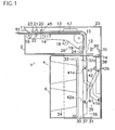
- a prior art bill handling apparatus 1 comprises a validator 2 provided with an inlet 11 into which a bill 44 is inserted, and a stacker 4 defining a storage chamber 30 for accumulating bills 44 considered genuine by validator 2.
- Validator 2 comprises a convey device 26 for transporting bill 44 inserted from inlet 11 along a generally L-shaped passageway 13 extending from inlet 11 to an outlet 12, and a control circuit 47 provided in validator 2 for supplying convey device 26 with drive signals.
- Convey device 26 and control circuit 47 provided in validator 2 are disposed in a L-shaped frame 25 made of metallic panels.
- Convey device 26 comprises convey belts 14 for transporting bill 44 along passageway 13, and drive pulleys 15 for driving convey belts 14, and a plurality of idle rollers 16 to 19 for supporting convey belts 14.
- a detection sensor 45 that comprises an optical sensor 20 for detecting an optical feature of bill 44 moving along passageway 13, and a magnetic sensor 21 for detecting a magnetic feature of bill 44.
- a pinch roller 22 is positioned opposite to the magnetic sensor 21 to push bill 44 toward magnetic sensor 21.
- Inlet sensor 23 located at inlet 11 detects insertion of bill 44 into inlet 11.
- An outlet sensor 24 located at outlet 12 detects discharge of bill 44 from validator 2.
- each of inlet sensor 23 and outlet sensor 24 comprises photocoupler of light emitting diode and photo-transistor
- optical sensor 20 comprises photocoupler of infrared ray emitting diode and photo-transistor.
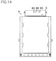
- Removably attached to a bottom of validator 2 is portable or mobile stacker 4 that, as illustrated in Figure 1 , comprises a cash box 6 formed with a storage chamber 30 and a housing 31.
- Storage chamber 30 receives a back plate 33 and a compression spring 34 for resiliently urging back plate 33 toward housing 31.
- a pusher 35 is mounted in housing 31 to press supplied bill 44 into cash box 6.
- Pusher 35 comprises a push plate 37 for pressing bill 44 into storage chamber 30, a link mechanism 36 connected to push plate 37 at the one end for driving push plate 37, and a rack 38 connected to the other end of link mechanism 36.
- Link mechanism 36 comprises a pair of links 41, 42 connected to each other to form an X shape.
- Link 41 has one end 41a rotatably connected to push plate 37 and the other end 41b rotatably connected to cash box 6.
- Link 42 has one end 42a rotatably connected to push plate 37 and the other end 42b rotatably connected to rack 38 that is meshed with a pinion 43 driven by a convey motor 50 provided in validator 2.
- Output gear 50a mounted on output shaft of convey motor 50 is drivingly connected to a first gear 52 mounted on a first shaft 53 through a reduction device 60.
- a second gear 54 mounted on first shaft 53 is engaged with a third gear 55 protruded from validator 2.
- Third gear 55 is drivingly connected to a sixth gear 58 through fourth and fifth gears 56 and 57.
- a sixth gear 58 has a pinion shaft 59 on which pinion 43 is mounted.
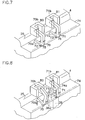
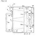
- an attachment lever 70 and a stack lever 71 have a generally similar shape, and are rotatably mounted on shafts 72, 73 mounted on frame 25 between the original position shown in Figure 7 and operative position shown in Figure 9 .
- Attachment lever 70 has a round end 70a to which a cam portion 74 of stacker 4 may be brought into contact.
- Stack lever 71 has a round end 71a to which an end 38a of rack 38 may be brought into contact.
- attachment lever 70 and stack lever 71 are resiliently urged toward their original positions respectively by springs 75, 76.
- the other end 70b of attachment lever 70 is positioned within an attachment sensor 80 of light emitting diode and light receiving transistor.
- the other end 71b of stack lever 71 is positioned within stack sensor 81 of light emitting diode and light receiving transistor.
- cam portion 74 comes into contact to round end 70a of attachment lever 70 to rotate attachment lever 70 in the clockwise direction from the original position of Figure 7 to the operative position of Figures 8 and 9 against resilient force of spring 75 and self-weight of attachment lever 70 so that attachment sensor 80 detects attachment of stacker 4 to validator 2 because the other end 70b of attachment lever 70 is removed from attachment sensor 80.
- Push plate 37 is in the blocking position shown in Figure 1 wherein push plate 37 covers channel 32a of cash box 6 to prevent unauthorized drawing of bill 44 from stacker 4.
- push plate 37 presses bill 44 to the stacked position to release the engagement of rack 38 with stack lever 71 that is then returned to the original position of Figure 6 .
- rack 38 moves stack lever 71 to the operative position of Figure 9 against resilient force of spring 76 and own weight of stack lever 71.
- attachment lever 70 and stack lever 71 rotatably mounted on frame 25
- other means may be provided for example such as attachment rod and stack rod each slidable on frame 25.
- an inlet sensor 23, an optical sensor 20, attachment sensor 80 and stack sensor 81 are connected through an amplifier 48 to input terminals of a control circuit 47 whose output terminal is connected to a motor control circuit 46 for controlling a convey motor 50.
- detection sensor 45 detects physical feature, namely optical and magnetic patterns of bill 44 routed to control circuit 47 that validates bill 44 and decides denomination of bill 44 in view of electric signals indicative of physical features of bill 44.
- the read data is stored in control circuit 47 as bill information.
- inlet sensor 23 detects insertion of bill 44 to produce a detection signal to input terminal of control circuit 47 through amplifier 48.
- control circuit 47 forwards a drive signal to motor control circuit 46 of convey device 26 to drive convey motor 50 and drive pulley 15 in the forward direction so that convey belts 14 carries bill 44 inwardly along passageway 13.
- convey motor 50 is rotated in one direction to upwardly move rack 38 as shown in Figure 4 and simultaneously move push plate 37 from the blocking position to the acceptant position so that bill 44 is carried in the standby position from channel 32a between back plate 33 and push plate 37.
- Discharge sensor 24 detects arrival of bill 44 at the standby position.
- rack 38 is downwardly moved and bill 44 is pressed into cash box 6 by push plate 37 that is urged toward back plate 33 by link mechanism 36.
- Stack lever 71 of Figure 7 automatically detects movement of push plate 37 to certainly and forcibly put bill 44 into cash box 6 by operation of push plate 37 at the accurate timing.
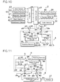
- FIG. 10 shows an electric circuit used in a new intelligent cash box system that is provided in validator 2 and stacker 4 with an intelligent storage 5.
- control circuit 47 comprises a code memory 32 as a part thereof, and a validator light emitter 61 and a validator light receiver 63 each connected to control circuit 47.
- Validator light emitter 61 comprises a transistor 64 as a validator switching element, and a light emitting diode 62 as a validator light emitting element connected to one of main terminals, namely an emitter of transistor 64.
- a control terminal, namely base of transistor 64 is connected to control circuit 47, and the other of the main terminals, namely a collector is connected to a power sources not shown.
- Validator light emitter 63 comprises a light receiving transistor 65 connected to control circuit 47.
- Intelligent storage 5 mounted in stacker 4 comprises a tracking memory 99, a stack light emitter 66, a stack light receiver 67, a stack control circuit 87 connected to tracking memory 99, stack light receiver 66 and stack light emitter 67, and a battery 98 for supplying electric power to each circuit of intelligent storage 5.
- tracking memory 99 has computing or calculating means for counting denomination or type and number of bills 44 scanned by detection sensor 45, but control circuit 47 or code memory 32 may have similar computing or calculating means for counting denomination or type and number of bills 44 as required.
- Tracking memory 99 may be a part of stack control circuit 87.
- Stack light emitter 66 comprises a transistor 86 as a stacker switching element, and a light emitting diode 85 as a stacker light emitting element connected to emitter, one of main terminals of transistor 86.
- Control terminal or base of transistor 86 is connected to stack control circuit 87, and collector or the other of main terminals of transistor 86 is grounded.
- Stack light receiver 67 comprises a light receiving transistor 88 as a light receiving element, and a resistor 84 for grounding emitter of light receiving transistor 88.
- Collector of light receiving transistor 88 is connected to stack control circuit 87.
- FET field effect transistor
- light emitting diode 62 of validator light emitter 61 is incorporated with light receiving transistor 88 of intelligent storage 5 without contact to each other to form a first photocoupler as shown in Figure 10 .
- light receiving transistor 65 of validator light receiver 63 is incorporated with light emitting diode 85 of intelligent storage 5 without contact to each other to form a second photocoupler.
- Light receiving transistor 65 receives light pulses indicative of information from light emitting diode 85 to confirm the status of stack control circuit 87 by control circuit 47 for example on whether previous information in tracking memory 99 has been deleted or whether unnecessary information is stored in tracking memory 99.
- an information collector 8 comprises a collection light emitter 39, a collection light receiver 40, a collection control circuit 94 connected to collection light emitter 39 and collection light receiver 40 at each input terminal, and a printer 27 connected to an output terminal of collection control circuit 94.
- Collection light emitter 39 comprises a transistor 97 with a control terminal or base connected to collection control circuit 94, and a light emitting diode 96 connected to emitter of transistor 97 whose collector is grounded.
- Collection light receiver 40 comprises a light receiving transistor 95 connected between collection control circuit 94 and earth or ground.
- control circuit 47 confirms the status of stack control circuit 87 whether tracking memory 99 contains any information or unnecessary information or whether tracking memory 99 can do its function well.
- a printer 7 is connected to a supervising computer 28 to record a code on a card 3 by printer 7 and issue card 3 from printer 7 so that issued card 3 bears the recorded code for identifying a specific bill handling apparatus, and the code can be optically or magnetically read out by detection sensor 45.
- the code is recorded with bar codes, symbols, numerals or alphabets on card 3 or by perforating card 3 to form a punch card to denote a machine number for identifying a parent slot machine.
- the recorded code includes invisible, indecipherable or incomprehensible letters, devices, symbols or alphabets.
- the code can be recorded on card 3 with ferrous ink to magnetically detect the code for example with a magnetic head.
- an entertainment area equipped with a number of gaming machines that each has a bill handling apparatus with a stacker 4 for accumulating bills 44 to be collected.
- Each bill handling apparatus should store a code as a supervision number for identifying the gaming machine on which bill handling apparatus is mounted.
- supervising computer 28 with printer 7 provides a card issue machine for dispensing cards 3 that bear recorded or printed different codes for identifying the gaming machines or validators 2.
- inlet sensor 23 detects insertion of card 3 to produce a detection signal to control circuit 47 that supplies drive signals to motor control circuit 46. Accordingly, convey motor 50 rotates in the forward direction to inwardly move card 3 along passageway 13 by driving convey belts 14, while detection sensor 45 scans and converts the code on card 3 into electric signals to control circuit 47 to store the code in code memory 32. Then, control circuit 47 provides motor control circuit 46 with reverse drive signals to rotate convey motor 50 in the reverse direction so that card 3 is returned to inlet 11.
- stacker 4 with intelligent storage 5 is attached in position within frame 25 of validator 2 so that attachment lever 70 rotates from the original position of Figure 7 to the operative position of Figure 9 , and attachment sensor 80 detects installation of stacker 4 to generate a detection signal to control circuit 47.
- control circuit 47 After control circuit 47 receives the detection signal from attachment sensor 80, control circuit 47 forwards pulse array signals indicative of code data stored in code memory 32 to base of transistor 64 to intermittently drive transistor 64 in the ON-OFF mode. In this case, control circuit 47 receives parallel signals of code information stored in code memory 32, and converts them into series pulse array signals indicated by binary code of "0" and "1" for base of transistor 64. Operation of transistor 64 in the ON-OFF mode causes light emitting diode 62 to blink in accordance with series pulse array signals, and light receiving transistor 88 receives optical pulse signals from light emitting diode 62 and transmits them to stack control circuit 87 that forwards the series signals to tracking memory 99 for storage therein as code information.
- stack control circuit 87 supplies drive signals to base of transistor 86 to intermittently operate transistor 86 in the ON-OFF mode and thereby cause light emitting diode 85 of intelligent storage 5 to blink in the predetermined mode.
- Light receiving transistor 65 of validator light receiver 63 receives light signals from light emitting diode 85 and supplies them to control circuit 47 to confirm storage of code information in stack control circuit 87 or tracking memory 99.
- light receiving transistor 90 receives disturbing light before attachment of stacker 4 to frame 25, electric current flows through light receiving transistor 90 to reduce gate voltage of FET 91 that is then turned OFF so that pulse array signals are not routed to stack control circuit 87 although light receiving transistor 88 receives light signals from light emitting diode 62. Pulse array signals stored as code information in stack control circuit 87 or tracking memory 99 cannot be decoded unless they are read out through a specific decoding software.
- control circuit 47 After that, in use of gaming machine, users throw each bill 44 into inlet 11 and detection sensor 45 detects physical feature of bill 44 moving along passageway 13 and forwards it to control circuit 47 that validates authenticity of bill 44.
- control circuit 47 decides bill 44 as genuine, bill 44 is accumulated in stacker 4.
- Control circuit 47 transmits electric signals indicative of denomination or type and value of genuine bill 44 as bill information to tracking memory 99 through stacker control circuit 47 for storage of bill information in tracking memory 99, each time bill 44 is stacked in stacker 4, while computing means in tracking memory 99 calculates total number or total of each denomination of stored bills 44.
- control circuit 47 converts parallel signals of bill information into series pulse array signals indicated by binary code of "0" and "1", and sends them to base of transistor 64.
- transistor 64 in the ON-OFF mode causes light emitting diode 62 to blink in accordance with the series pulse array signals, and light receiving transistor 88 receives light signals form light emitting diode 62 and transmits them to stack control circuit 87 and tracking memory 99 for storage therein as bill information.
- stack control circuit 87 again supplies drive signals to base of transistor 86 to intermittently operate transistor 86 in the ON-OFF mode and thereby cause light emitting diode 85 of intelligent storage 5 to blink in the predetermined mode so that light receiving transistor 65 of validator light receiver 63 receives light signals from light emitting diode 85 and supplies them to control circuit 47 to confirm storage of bill information in stack control circuit 87 or tracking memory 99.
- control circuit 47 may transmit code information and bill information to stack control circuit 87 or tracking memory 99 for storage of these information therein each time bill 44 is stacked in stacker 4, not when control circuit 47 receives detection signal from attachment sensor 80.
- light receiving transistor 88 receives light signals from light emitting diode 96 to supply the coded signals to stack control circuit 87 that thereby provides base of transistor 86 with drive signals to drive transistor 86 in the ON-OFF mode to transmit code information and bill information stored in tracking memory 99 to collection control circuit 94.
- light emitting diode 86 flashes to generate light signals that are received by light receiving transistor 95.
- collection control circuit 94 provides printer 27 with code information for identifying the gaming machine and bill information for indicating denomination or type and value of bills to record these information on sheet 9 by printer 27.
- data printed on sheet 9 is then optically read by a scanner 10, and forwarded from scanner 10 to a confirmative computer 29.
- bill information indicated on display of confirmative computer 29 corresponds to the number and denomination or type of bills 44 collected from cash box 6 as mentioned above
- the data is stored in confirmative computer 29 for supervision.
- data stored in tracking memory 99 of stacker 4 is deleted when information collector 8 finishes reading out data from tracking memory 99, when a reset switch (not shown) in stacker is operated or when light receiving transistor 88 receives light signals from light emitting diode 62 after stacker 4 is attached to frame 25 for reuse of stacker 4, or in one of other cases.
- information collector 8 may directly be connected to confirmative computer 29 via conducting wires to directly supply the information to confirmative computer 29 for input or printing.
- Embodiments according to the present invention can produce the following advantages utilizing card 3 bearing code information:
- embodiments of the present invention can present the following advantages utilizing photocouplers:
Landscapes
- General Physics & Mathematics (AREA)
- Physics & Mathematics (AREA)
- Engineering & Computer Science (AREA)
- Business, Economics & Management (AREA)
- Accounting & Taxation (AREA)
- General Business, Economics & Management (AREA)
- Theoretical Computer Science (AREA)
- Strategic Management (AREA)
- Computer Networks & Wireless Communication (AREA)
- Microelectronics & Electronic Packaging (AREA)
- Computer Security & Cryptography (AREA)
- Finance (AREA)
- Health & Medical Sciences (AREA)
- General Health & Medical Sciences (AREA)
- Toxicology (AREA)
- Control Of Vending Devices And Auxiliary Devices For Vending Devices (AREA)
- Inspection Of Paper Currency And Valuable Securities (AREA)
- Financial Or Insurance-Related Operations Such As Payment And Settlement (AREA)
- Pile Receivers (AREA)
Claims (10)
- Geldscheinverarbeitungsvorrichtung, Folgendes umfassend:ein Validierungsmittel (2) zum Attestieren eines Geldscheins (44), der in den Einlass (11) des Validierungsmittels eingeführt wird, ein Stapelmittel (4), ablösbar auf das Validierungsmittel montiert, um die vom Validierungsmittel authentifizierten Geldscheine aufzuschichten, und ein intelligentes Geldkassettensystem, dazu angepasst, Information vom Validierungsmittel an das Stapelmittel zu übertragen;wobei das intelligente Geldkassettensystem umfasst: eine Karte (3), die mindestens einen auf die Karte aufgezeichneten Code enthält, der die Geldscheinverarbeitungsvorrichtung identifiziert, wobei die Karte befähigt ist, in den Einlass des Validierungsmittels eingeführt zu werden, das dazu angepasst ist, den Code durch ein Sensormittel (45) zu detektieren und den Code in einem Steuermittel (47) als Codeinformation im Validierungsmittel zu speichern, und einen intelligenten Speicher (5), der im Stapelmittel in Kommunikation mit dem Steuermittel des Validierungsmittels bereitgestellt ist und dazu angepasst ist, die Codeinformation und Geldscheininformation vom Steuermittel zu empfangen und diese Information im intelligenten Speicher zu speichern,wobei die Geldscheininformation Daten der Geldscheine enthält, die in einer Speicherkammer (30) des Stapelmittels empfangen werden und vom Steuermittel an den intelligenten Speicher übertragen werden.
- Geldscheinverarbeitungsvorrichtung nach Anspruch 1, worin das Validierungsmittel (2) Folgendes umfasst: Beförderungsmittel (26) zum Transportieren des in den Einlass (11) eingeführten Geldscheins entlang einem Durchgang (13), das Sensormittel (45) zum Detektieren eines physikalischen Merkmals des transportierten Geldscheins, um elektrische Signale zu erzeugen, die für das physikalische Merkmal des Geldscheins bezeichnend sind, und das Steuermittel (47) zum Attestieren des Geldscheins auf der Basis von Ausgangssignalen des Sensormittels und auch zum Weiterleiten von Ansteuersignalen an das Beförderungsmittel;
wobei das Stapelmittel (4) die Speicherkammer (30) zum Empfangen der Geldscheine umfasst, die vorn Steuermittel als echt angesehen werden und vom Beförderungsmittel durch den Durchgang übertragen werden. - Geldscheinverarbeitungsvorrichtung nach Anspruch 2, außerdem ein Informationssammelmittel (8) umfassend, das unabhängig vom Validierungsmittel (2) bereitgestellt ist, um die Codeinformation und Geldscheininformation vom intelligenten Speicher (5) des Stapelmittels (4) zu empfangen, das vom Validierungsmittel weggenommen ist.
- Geldscheinverarbeitungsvorrichtung nach Anspruch 2, außerdem eine Kartenausgabemaschine (7) zum Aufzeichnen des Codes auf die Karte (3) und zum Ausgeben der Karte umfassend.
- Geldsebeinverarbeitungsvorrichtung nach Anspruch 2, worin mindestens eins des Steuermittels (47) und des intelligenten Speichers (5) Rechenmittel umfasst, um die Anzahl und Art oder den Nennbetrag der vom Sensormittel detektierten Geldscheine zu berechnen.
- Geldscheinvelarbeitungsvorrichtung nach Anspruch 4, worin die Kartenausgabemaschine (7) den aus Barcodes, Symbolen, Ziffern oder Alphabeten ausgewählten Code auf die Karte (3) druckt oder aufzeichnet oder die Karte perforiert, um eine Lochkarte zu bilden.
- Geldscheinverarbeitungsvorrichtung nach Anspruch 2, worin das intelligente Geldkassettensystem außerdem Photokopplermittel (62, 88 und 65, 85) umfasst, die zwischen dem Steuermittel (47) und dem intelligenten Speicher (5) bereitgestellt sind, um die Codeinformation und Geldscheininformation im kontaktlosen Zustand des Steuermittels und des intelligenten Speichers durch die Photokoppler-mittel zu übertragen.
- Geldscheinverarbeitungsvorrichtung nach Anspruch 3, worin das intelligente Geldkassettensystem außerdem Photokopplermittel (95, 85 und 96, 88) umfasst, die zwischen dem intelligenten Speicher (5) und einer Sammelsteuerschaltung (94) bereitgestellt sind, um die Codeinformation und Geldscheininformation im kontaktlosen Zustand des intelligenten Speichers und der Sammelsteuerschaltung durch die Photokopplermittel zu übertragen.
- Geldscheinverarbeitungsvorrichtung nach Anspruch 2, worin das Steuermittel (47) einen Codespeicher (32) zum Speichern der Codeinformation umfasst und der intelligente Speicher (5) einen Tracking-Speicher (99) zum Speichern von Codeinformation und Geldsdeininformation umfasst.
- Geldscheinverarbeitungsvorrichtung nach Anspruch 2, worin das Validierungsmittel (2) einen Validator-Lichtemitter (62) umfasst, der an das Steuermittel (47) angeschlossen ist, wobei der intelligente Speicher (5) eine Stapelsteuerschaltung (87) und einen Stapel-Lichtempfänger (88) umfasst, der an die Stapelsteuerschaltung angeschlossen ist,
wobei der Stapel-Lichtempfänger (88) mit Abstand gegenüber dem Validator-Lichtemitter (62) angeordnet ist, um einen ersten Photokoppler des Validator-Lichtemitters und Stapel-Lichtempfängers bereitzustellen, nachdem das Stapelmittel an das Validierungsmittel angeschlossen ist,
wobei die Stapelsteuerschaltung Lichtsignale empfängt, die für die Codeinformation und Geldscheininformation vom Steuermittel durch den ersten Photokoppler bezeichnend sind, und diese Signale speichert.
Applications Claiming Priority (3)
| Application Number | Priority Date | Filing Date | Title |
|---|---|---|---|
| JP2002322463A JP3909841B2 (ja) | 2002-11-06 | 2002-11-06 | 紙幣取扱装置及び紙幣情報伝達法 |
| JP2002322463 | 2002-11-06 | ||
| PCT/JP2003/014142 WO2004042665A1 (en) | 2002-11-06 | 2003-11-06 | Billhandling apparatus and method for transmitting code information |
Publications (3)
| Publication Number | Publication Date |
|---|---|
| EP1559078A1 EP1559078A1 (de) | 2005-08-03 |
| EP1559078A4 EP1559078A4 (de) | 2007-07-11 |
| EP1559078B1 true EP1559078B1 (de) | 2012-12-26 |
Family
ID=32310390
Family Applications (1)
| Application Number | Title | Priority Date | Filing Date |
|---|---|---|---|
| EP03810623A Expired - Lifetime EP1559078B1 (de) | 2002-11-06 | 2003-11-06 | Geldscheinverarbeitungsvorrichtung und verfahren zum übertragen von codeinformationen |
Country Status (11)
| Country | Link |
|---|---|
| US (2) | US7909152B2 (de) |
| EP (1) | EP1559078B1 (de) |
| JP (1) | JP3909841B2 (de) |
| KR (1) | KR100985623B1 (de) |
| CN (1) | CN100410973C (de) |
| AU (1) | AU2003276714B2 (de) |
| CA (1) | CA2504996C (de) |
| ES (1) | ES2401984T3 (de) |
| RU (1) | RU2304310C2 (de) |
| WO (1) | WO2004042665A1 (de) |
| ZA (1) | ZA200504039B (de) |
Families Citing this family (29)
| Publication number | Priority date | Publication date | Assignee | Title |
|---|---|---|---|---|
| JP4454023B2 (ja) * | 2005-02-17 | 2010-04-21 | 株式会社ユニバーサルエンターテインメント | 紙幣処理装置 |
| CH704737B1 (de) | 2005-05-27 | 2012-10-15 | Peter Villiger | Sicherheitskassette, Sicherungsbehältnis und Sicherungssystem. |
| EP1920413B1 (de) * | 2005-07-27 | 2019-05-22 | Crane Payment Innovations, Inc. | Kassette zum speichern von geldscheinen und dergleichen |
| JP4901227B2 (ja) * | 2006-01-27 | 2012-03-21 | 株式会社東芝 | 紙葉類処理システム |
| ITMI20060407A1 (it) * | 2006-03-07 | 2007-09-08 | Razzaboni Cima Spa | Dispositivo e metodo per l'immagazzinamento e l'erogazione di banconote |
| US8851373B2 (en) * | 2006-06-14 | 2014-10-07 | Mei, Inc. | Tracking information in a note handling facility |
| RU2413991C2 (ru) * | 2006-09-11 | 2011-03-10 | Фьючер Текнолоджи Инститьют Корпорейшн | Система распознавания фальшивых карт, устройство записи информации определения подлинности и устройство распознавания фальшивых карт |
| CA2703127A1 (en) * | 2006-10-20 | 2008-05-02 | Coin Acceptors, Inc. | A method of receiving and paying out bills |
| TWI301598B (en) * | 2006-10-24 | 2008-10-01 | Int Currency Tech | Calibration system and method thereof |
| JP5269506B2 (ja) * | 2007-10-24 | 2013-08-21 | 株式会社ユニバーサルエンターテインメント | 紙幣処理装置 |
| JP5188167B2 (ja) | 2007-12-20 | 2013-04-24 | 株式会社ユニバーサルエンターテインメント | 紙葉類処理装置 |
| US20090223776A1 (en) * | 2008-03-05 | 2009-09-10 | International Currency Technologies Corporation | Bill acceptor with licence/bill recognition |
| US20100320056A1 (en) * | 2008-03-31 | 2010-12-23 | International Currency Technologies Corporation | Bill acceptor that prevents arching of each received bill |
| US20090242353A1 (en) * | 2008-03-31 | 2009-10-01 | International Currency Technologies Corporation | Bill accetor |
| US8267238B2 (en) * | 2009-03-16 | 2012-09-18 | Glory Ltd. | Banknote depositing machine and banknote depositing method |
| AU2010241389B2 (en) * | 2009-11-16 | 2015-01-29 | Everi Technology Pty Ltd | Systems and methods for providing interaction with a terminal |
| CN102542654B (zh) * | 2010-12-17 | 2014-04-09 | 辽宁聚龙金融设备股份有限公司 | 一种纸币清分机、点钞机的磁性检测传感器安装结构 |
| EP2505530A3 (de) * | 2011-03-31 | 2013-05-22 | Glory Ltd. | Geldhandhabungssystem und Geldhandhabungsverfahren |
| JP5971147B2 (ja) * | 2013-02-14 | 2016-08-17 | 沖電気工業株式会社 | 媒体処理装置 |
| JP6121300B2 (ja) * | 2013-09-26 | 2017-04-26 | 日本電産サンキョー株式会社 | カードリーダ |
| JP6409502B2 (ja) * | 2014-03-31 | 2018-10-24 | 沖電気工業株式会社 | 媒体処理装置及び媒体取引装置 |
| JP2016057968A (ja) * | 2014-09-11 | 2016-04-21 | 沖電気工業株式会社 | 媒体取引装置 |
| CN107148641B (zh) * | 2014-10-03 | 2021-05-25 | 三菱电机株式会社 | 图像读取装置 |
| CN104331980A (zh) * | 2014-11-04 | 2015-02-04 | 广州御银自动柜员机技术有限公司 | 凭证扫描回收装置及其回收方法 |
| KR102312906B1 (ko) * | 2017-03-31 | 2021-10-15 | 효성티앤에스 주식회사 | 포터블 카세트 홀더 |
| JP6811140B2 (ja) * | 2017-04-12 | 2021-01-13 | 日本金銭機械株式会社 | 紙葉類鑑別装置、及び紙葉類鑑別システム |
| CN107067067A (zh) * | 2017-04-14 | 2017-08-18 | 永道无线射频标签(扬州)有限公司 | 单张票卡不同图案识别分拣的工作流程 |
| US20200372584A1 (en) * | 2019-05-23 | 2020-11-26 | Jcm American Corporation | Currency Tracking and Accounting Systems |
| JP7274003B1 (ja) | 2022-01-14 | 2023-05-15 | 日本金銭機械株式会社 | 紙幣処理装置 |
Family Cites Families (26)
| Publication number | Priority date | Publication date | Assignee | Title |
|---|---|---|---|---|
| GB2165383B (en) * | 1984-10-03 | 1988-05-25 | Ncr Co | Data sensing system for currency cassettes |
| JPS61253696A (ja) * | 1985-05-02 | 1986-11-11 | Hitachi Ltd | 半導体集積回路装置及びその製造方法 |
| JPS61253596A (ja) | 1985-05-07 | 1986-11-11 | 株式会社日立製作所 | 現金入出金装置 |
| FR2584516B1 (fr) * | 1985-07-02 | 1988-05-13 | Smh Alcatel | Procede et systeme de controle pour machines a affranchir |
| SE455653B (sv) * | 1987-08-11 | 1988-07-25 | Inter Innovation Ab | Anleggning for seker overforing av atminstone verdet av verdepapper fran ett flertal utspritt fordelade teminaler till en centralt placerad penninginrettning |
| GB8908528D0 (en) * | 1989-04-14 | 1989-06-01 | Ncr Co | Data transfer system for currency cassettes |
| JP3253335B2 (ja) * | 1992-01-20 | 2002-02-04 | 株式会社東芝 | 現金管理システム |
| GB2273840A (en) * | 1992-12-09 | 1994-06-29 | Sony Corp | Optically transmitting signals between measurement devices |
| JP2973385B2 (ja) * | 1992-12-30 | 1999-11-08 | 株式会社日本コンラックス | 自動販売機等の硬貨選別装置 |
| US5655961A (en) * | 1994-10-12 | 1997-08-12 | Acres Gaming, Inc. | Method for operating networked gaming devices |
| US5491326A (en) * | 1994-11-23 | 1996-02-13 | Xcp, Inc. | Card metering system |
| US5630755A (en) * | 1995-04-07 | 1997-05-20 | Coin Bill Validator, Inc. | Soft count tracking system |
| FR2732801B1 (fr) * | 1995-04-07 | 1997-06-06 | High Co | Dispositif et procede de traitement d'informations codees pour code a barres et carte a puce |
| US5743429A (en) * | 1995-09-26 | 1998-04-28 | Debit Dial Vending Corp. | Device for dispensing credit cards |
| US5662202A (en) * | 1995-11-24 | 1997-09-02 | Ardac Incorporated | Currency validator with cassette cash box |
| US5907141A (en) * | 1996-07-19 | 1999-05-25 | Mars Incorporated | Use of security coupons in connection with locking mechanisms for vending and gaming machines |
| JPH10261131A (ja) | 1997-03-21 | 1998-09-29 | Toshiba Corp | インテリジェント金庫、およびこのインテリジェント金庫を用いた現金処理システム |
| US6845905B2 (en) * | 1997-03-26 | 2005-01-25 | Vendingdata Corporation | Currency container tracking system and a currency container for use therewith |
| US6065672A (en) * | 1997-07-24 | 2000-05-23 | Currency Systems International | Method for currency distribution and management |
| US6109522A (en) * | 1997-11-28 | 2000-08-29 | Diebold, Incorporated | Automated banking machine with self auditing capabilities and system |
| US6164638A (en) * | 1997-11-28 | 2000-12-26 | Dicbold, Incorporates | Automated banking machine with currency recycling canisters |
| US6059090A (en) * | 1998-04-13 | 2000-05-09 | Agent Systems, Inc. | Configurable cashbox |
| EP1130551A3 (de) * | 2000-02-22 | 2004-01-21 | Glory Kogyo Kabushiki Kaisha | Geldscheinverarbeitungsmaschine |
| CN1145118C (zh) * | 2001-01-15 | 2004-04-07 | 福士电机株式会社 | 自动售货机控制装置 |
| US6896116B2 (en) * | 2002-06-18 | 2005-05-24 | Mars Incorporated | Bill acceptor |
| US6738690B2 (en) * | 2002-08-08 | 2004-05-18 | Pj Solutions, Inc. | Information management of supply flow of dispensed objects |
-
2002
- 2002-11-06 JP JP2002322463A patent/JP3909841B2/ja not_active Expired - Fee Related
-
2003
- 2003-11-05 US US10/702,533 patent/US7909152B2/en not_active Expired - Lifetime
- 2003-11-06 AU AU2003276714A patent/AU2003276714B2/en not_active Expired
- 2003-11-06 KR KR1020057008124A patent/KR100985623B1/ko not_active Expired - Fee Related
- 2003-11-06 ES ES03810623T patent/ES2401984T3/es not_active Expired - Lifetime
- 2003-11-06 WO PCT/JP2003/014142 patent/WO2004042665A1/en not_active Ceased
- 2003-11-06 CN CNB200380107188XA patent/CN100410973C/zh not_active Expired - Lifetime
- 2003-11-06 EP EP03810623A patent/EP1559078B1/de not_active Expired - Lifetime
- 2003-11-06 CA CA2504996A patent/CA2504996C/en not_active Expired - Lifetime
- 2003-11-06 RU RU2005117156/09A patent/RU2304310C2/ru active
-
2005
- 2005-05-19 ZA ZA200504039A patent/ZA200504039B/xx unknown
-
2006
- 2006-03-13 US US11/375,165 patent/US7913831B2/en not_active Expired - Lifetime
Also Published As
| Publication number | Publication date |
|---|---|
| JP2004157740A (ja) | 2004-06-03 |
| CA2504996A1 (en) | 2004-05-21 |
| JP3909841B2 (ja) | 2007-04-25 |
| ES2401984T3 (es) | 2013-04-26 |
| EP1559078A1 (de) | 2005-08-03 |
| ZA200504039B (en) | 2006-04-26 |
| CN1729489A (zh) | 2006-02-01 |
| KR100985623B1 (ko) | 2010-10-07 |
| WO2004042665A1 (en) | 2004-05-21 |
| AU2003276714B2 (en) | 2008-05-29 |
| CA2504996C (en) | 2012-07-17 |
| US7913831B2 (en) | 2011-03-29 |
| EP1559078A4 (de) | 2007-07-11 |
| KR20050070121A (ko) | 2005-07-05 |
| AU2003276714A1 (en) | 2004-06-07 |
| US7909152B2 (en) | 2011-03-22 |
| CN100410973C (zh) | 2008-08-13 |
| RU2005117156A (ru) | 2006-01-20 |
| US20040149817A1 (en) | 2004-08-05 |
| US20060151281A1 (en) | 2006-07-13 |
| RU2304310C2 (ru) | 2007-08-10 |
Similar Documents
| Publication | Publication Date | Title |
|---|---|---|
| EP1559078B1 (de) | Geldscheinverarbeitungsvorrichtung und verfahren zum übertragen von codeinformationen | |
| RU2113728C1 (ru) | Устройство для регистрации знаковой информации, напечатанной на документах (варианты) | |
| US6910625B2 (en) | Commercial self-service equipment | |
| US20020063035A1 (en) | Currency container tracking system and a currency container for use therewith | |
| EP1668489A2 (de) | System und verfahren zum bearbeiten von geld- und identifikationskarten in einer dokumentverarbeitungseinrichtung | |
| JPS584496A (ja) | 銀行紙幣、小切手、受領書、引換券等有価証書類の供出及び貯蔵を行なうための二目的型自動装置 | |
| WO1992017856A1 (en) | Remote credit card issuance apparatus and method | |
| CN101414394B (zh) | 票据验证和/或存储设备 | |
| US6993758B1 (en) | Method and apparatus for renewing software in a software-operated machine | |
| MX2014000236A (es) | Manipulador de documentos para juegos de mesa. | |
| CA2753931C (en) | Valuable paper treating system | |
| JP2000322632A (ja) | 貨幣等の取扱装置 | |
| JPS58161077A (ja) | カ−ド取引方式 | |
| JP2696089B2 (ja) | 自動取引装置 | |
| JPH10172066A (ja) | 紙幣装填システム | |
| CN118355420A (zh) | 自动货币兑换设备和方法 | |
| JPS61260387A (ja) | 振込取引方式 | |
| KR920004421B1 (ko) | 자동거래장치 | |
| JPH06215235A (ja) | 紙幣自動取引装置 | |
| JPS6382544A (ja) | 自動取引装置 | |
| KR20060042594A (ko) | 금융 자동화기기의 출금장치 | |
| JPH0632106B2 (ja) | 回数券処理装置 | |
| ZA200106515B (en) | Method and apparatus for renewing software in a software-operated machine. | |
| JPS59229376A (ja) | 通帳取扱装置 |
Legal Events
| Date | Code | Title | Description |
|---|---|---|---|
| PUAI | Public reference made under article 153(3) epc to a published international application that has entered the european phase |
Free format text: ORIGINAL CODE: 0009012 |
|
| 17P | Request for examination filed |
Effective date: 20050504 |
|
| AK | Designated contracting states |
Kind code of ref document: A1 Designated state(s): AT BE BG CH CY CZ DE DK EE ES FI FR GB GR HU IE IT LI LU MC NL PT RO SE SI SK TR |
|
| AX | Request for extension of the european patent |
Extension state: AL LT LV MK |
|
| DAX | Request for extension of the european patent (deleted) | ||
| RBV | Designated contracting states (corrected) |
Designated state(s): AT DE ES GB IT |
|
| A4 | Supplementary search report drawn up and despatched |
Effective date: 20070612 |
|
| RIC1 | Information provided on ipc code assigned before grant |
Ipc: G07D 11/00 20060101AFI20070606BHEP |
|
| 17Q | First examination report despatched |
Effective date: 20080128 |
|
| GRAP | Despatch of communication of intention to grant a patent |
Free format text: ORIGINAL CODE: EPIDOSNIGR1 |
|
| GRAS | Grant fee paid |
Free format text: ORIGINAL CODE: EPIDOSNIGR3 |
|
| GRAA | (expected) grant |
Free format text: ORIGINAL CODE: 0009210 |
|
| AK | Designated contracting states |
Kind code of ref document: B1 Designated state(s): AT DE ES GB IT |
|
| REG | Reference to a national code |
Ref country code: GB Ref legal event code: FG4D |
|
| REG | Reference to a national code |
Ref country code: AT Ref legal event code: REF Ref document number: 590816 Country of ref document: AT Kind code of ref document: T Effective date: 20130115 |
|
| REG | Reference to a national code |
Ref country code: DE Ref legal event code: R096 Ref document number: 60342978 Country of ref document: DE Effective date: 20130228 |
|
| PLBE | No opposition filed within time limit |
Free format text: ORIGINAL CODE: 0009261 |
|
| STAA | Information on the status of an ep patent application or granted ep patent |
Free format text: STATUS: NO OPPOSITION FILED WITHIN TIME LIMIT |
|
| 26N | No opposition filed |
Effective date: 20130927 |
|
| REG | Reference to a national code |
Ref country code: DE Ref legal event code: R097 Ref document number: 60342978 Country of ref document: DE Effective date: 20130927 |
|
| PGFP | Annual fee paid to national office [announced via postgrant information from national office to epo] |
Ref country code: IT Payment date: 20221124 Year of fee payment: 20 Ref country code: GB Payment date: 20221125 Year of fee payment: 20 Ref country code: DE Payment date: 20221123 Year of fee payment: 20 Ref country code: AT Payment date: 20221121 Year of fee payment: 20 |
|
| PGFP | Annual fee paid to national office [announced via postgrant information from national office to epo] |
Ref country code: ES Payment date: 20230125 Year of fee payment: 20 |
|
| P01 | Opt-out of the competence of the unified patent court (upc) registered |
Effective date: 20230524 |
|
| REG | Reference to a national code |
Ref country code: DE Ref legal event code: R071 Ref document number: 60342978 Country of ref document: DE |
|
| REG | Reference to a national code |
Ref country code: GB Ref legal event code: PE20 Expiry date: 20231105 |
|
| REG | Reference to a national code |
Ref country code: ES Ref legal event code: FD2A Effective date: 20231201 |
|
| REG | Reference to a national code |
Ref country code: AT Ref legal event code: MK07 Ref document number: 590816 Country of ref document: AT Kind code of ref document: T Effective date: 20231106 |
|
| PG25 | Lapsed in a contracting state [announced via postgrant information from national office to epo] |
Ref country code: GB Free format text: LAPSE BECAUSE OF EXPIRATION OF PROTECTION Effective date: 20231105 |
|
| PG25 | Lapsed in a contracting state [announced via postgrant information from national office to epo] |
Ref country code: ES Free format text: LAPSE BECAUSE OF EXPIRATION OF PROTECTION Effective date: 20231107 |
|
| PG25 | Lapsed in a contracting state [announced via postgrant information from national office to epo] |
Ref country code: GB Free format text: LAPSE BECAUSE OF EXPIRATION OF PROTECTION Effective date: 20231105 Ref country code: ES Free format text: LAPSE BECAUSE OF EXPIRATION OF PROTECTION Effective date: 20231107 |