EP1558796B1 - Vorrichtung und verfahren zum einspeisen einer flüssigen farbe in eine polymerschmelze - Google Patents
Vorrichtung und verfahren zum einspeisen einer flüssigen farbe in eine polymerschmelze Download PDFInfo
- Publication number
- EP1558796B1 EP1558796B1 EP20030766144 EP03766144A EP1558796B1 EP 1558796 B1 EP1558796 B1 EP 1558796B1 EP 20030766144 EP20030766144 EP 20030766144 EP 03766144 A EP03766144 A EP 03766144A EP 1558796 B1 EP1558796 B1 EP 1558796B1
- Authority
- EP
- European Patent Office
- Prior art keywords
- pump
- metering
- feed
- inlet
- tank
- Prior art date
- Legal status (The legal status is an assumption and is not a legal conclusion. Google has not performed a legal analysis and makes no representation as to the accuracy of the status listed.)
- Expired - Lifetime
Links
Images
Classifications
-
- D—TEXTILES; PAPER
- D01—NATURAL OR MAN-MADE THREADS OR FIBRES; SPINNING
- D01D—MECHANICAL METHODS OR APPARATUS IN THE MANUFACTURE OF ARTIFICIAL FILAMENTS, THREADS, FIBRES, BRISTLES OR RIBBONS
- D01D1/00—Treatment of filament-forming or like material
- D01D1/06—Feeding liquid to the spinning head
-
- F—MECHANICAL ENGINEERING; LIGHTING; HEATING; WEAPONS; BLASTING
- F04—POSITIVE - DISPLACEMENT MACHINES FOR LIQUIDS; PUMPS FOR LIQUIDS OR ELASTIC FLUIDS
- F04C—ROTARY-PISTON, OR OSCILLATING-PISTON, POSITIVE-DISPLACEMENT MACHINES FOR LIQUIDS; ROTARY-PISTON, OR OSCILLATING-PISTON, POSITIVE-DISPLACEMENT PUMPS
- F04C14/00—Control of, monitoring of, or safety arrangements for, machines, pumps or pumping installations
- F04C14/08—Control of, monitoring of, or safety arrangements for, machines, pumps or pumping installations characterised by varying the rotational speed
-
- B—PERFORMING OPERATIONS; TRANSPORTING
- B29—WORKING OF PLASTICS; WORKING OF SUBSTANCES IN A PLASTIC STATE IN GENERAL
- B29B—PREPARATION OR PRETREATMENT OF THE MATERIAL TO BE SHAPED; MAKING GRANULES OR PREFORMS; RECOVERY OF PLASTICS OR OTHER CONSTITUENTS OF WASTE MATERIAL CONTAINING PLASTICS
- B29B7/00—Mixing; Kneading
- B29B7/80—Component parts, details or accessories; Auxiliary operations
- B29B7/88—Adding charges, i.e. additives
- B29B7/94—Liquid charges
-
- B—PERFORMING OPERATIONS; TRANSPORTING
- B29—WORKING OF PLASTICS; WORKING OF SUBSTANCES IN A PLASTIC STATE IN GENERAL
- B29C—SHAPING OR JOINING OF PLASTICS; SHAPING OF MATERIAL IN A PLASTIC STATE, NOT OTHERWISE PROVIDED FOR; AFTER-TREATMENT OF THE SHAPED PRODUCTS, e.g. REPAIRING
- B29C48/00—Extrusion moulding, i.e. expressing the moulding material through a die or nozzle which imparts the desired form; Apparatus therefor
- B29C48/03—Extrusion moulding, i.e. expressing the moulding material through a die or nozzle which imparts the desired form; Apparatus therefor characterised by the shape of the extruded material at extrusion
- B29C48/09—Articles with cross-sections having partially or fully enclosed cavities, e.g. pipes or channels
-
- B—PERFORMING OPERATIONS; TRANSPORTING
- B29—WORKING OF PLASTICS; WORKING OF SUBSTANCES IN A PLASTIC STATE IN GENERAL
- B29C—SHAPING OR JOINING OF PLASTICS; SHAPING OF MATERIAL IN A PLASTIC STATE, NOT OTHERWISE PROVIDED FOR; AFTER-TREATMENT OF THE SHAPED PRODUCTS, e.g. REPAIRING
- B29C48/00—Extrusion moulding, i.e. expressing the moulding material through a die or nozzle which imparts the desired form; Apparatus therefor
- B29C48/25—Component parts, details or accessories; Auxiliary operations
- B29C48/285—Feeding the extrusion material to the extruder
- B29C48/29—Feeding the extrusion material to the extruder in liquid form
-
- B—PERFORMING OPERATIONS; TRANSPORTING
- B29—WORKING OF PLASTICS; WORKING OF SUBSTANCES IN A PLASTIC STATE IN GENERAL
- B29C—SHAPING OR JOINING OF PLASTICS; SHAPING OF MATERIAL IN A PLASTIC STATE, NOT OTHERWISE PROVIDED FOR; AFTER-TREATMENT OF THE SHAPED PRODUCTS, e.g. REPAIRING
- B29C48/00—Extrusion moulding, i.e. expressing the moulding material through a die or nozzle which imparts the desired form; Apparatus therefor
- B29C48/25—Component parts, details or accessories; Auxiliary operations
- B29C48/36—Means for plasticising or homogenising the moulding material or forcing it through the nozzle or die
- B29C48/365—Means for plasticising or homogenising the moulding material or forcing it through the nozzle or die using pumps, e.g. piston pumps
- B29C48/37—Gear pumps
-
- D—TEXTILES; PAPER
- D01—NATURAL OR MAN-MADE THREADS OR FIBRES; SPINNING
- D01D—MECHANICAL METHODS OR APPARATUS IN THE MANUFACTURE OF ARTIFICIAL FILAMENTS, THREADS, FIBRES, BRISTLES OR RIBBONS
- D01D1/00—Treatment of filament-forming or like material
- D01D1/06—Feeding liquid to the spinning head
- D01D1/065—Addition and mixing of substances to the spinning solution or to the melt; Homogenising
-
- F—MECHANICAL ENGINEERING; LIGHTING; HEATING; WEAPONS; BLASTING
- F04—POSITIVE - DISPLACEMENT MACHINES FOR LIQUIDS; PUMPS FOR LIQUIDS OR ELASTIC FLUIDS
- F04B—POSITIVE-DISPLACEMENT MACHINES FOR LIQUIDS; PUMPS
- F04B13/00—Pumps specially modified to deliver fixed or variable measured quantities
-
- F—MECHANICAL ENGINEERING; LIGHTING; HEATING; WEAPONS; BLASTING
- F04—POSITIVE - DISPLACEMENT MACHINES FOR LIQUIDS; PUMPS FOR LIQUIDS OR ELASTIC FLUIDS
- F04B—POSITIVE-DISPLACEMENT MACHINES FOR LIQUIDS; PUMPS
- F04B23/00—Pumping installations or systems
- F04B23/04—Combinations of two or more pumps
- F04B23/08—Combinations of two or more pumps the pumps being of different types
- F04B23/14—Combinations of two or more pumps the pumps being of different types at least one pump being of the non-positive-displacement type
-
- F—MECHANICAL ENGINEERING; LIGHTING; HEATING; WEAPONS; BLASTING
- F04—POSITIVE - DISPLACEMENT MACHINES FOR LIQUIDS; PUMPS FOR LIQUIDS OR ELASTIC FLUIDS
- F04C—ROTARY-PISTON, OR OSCILLATING-PISTON, POSITIVE-DISPLACEMENT MACHINES FOR LIQUIDS; ROTARY-PISTON, OR OSCILLATING-PISTON, POSITIVE-DISPLACEMENT PUMPS
- F04C11/00—Combinations of two or more machines or pumps, each being of rotary-piston or oscillating-piston type; Pumping installations
- F04C11/001—Combinations of two or more machines or pumps, each being of rotary-piston or oscillating-piston type; Pumping installations of similar working principle
-
- F—MECHANICAL ENGINEERING; LIGHTING; HEATING; WEAPONS; BLASTING
- F04—POSITIVE - DISPLACEMENT MACHINES FOR LIQUIDS; PUMPS FOR LIQUIDS OR ELASTIC FLUIDS
- F04C—ROTARY-PISTON, OR OSCILLATING-PISTON, POSITIVE-DISPLACEMENT MACHINES FOR LIQUIDS; ROTARY-PISTON, OR OSCILLATING-PISTON, POSITIVE-DISPLACEMENT PUMPS
- F04C13/00—Adaptations of machines or pumps for special use, e.g. for extremely high pressures
- F04C13/001—Pumps for particular liquids
-
- B—PERFORMING OPERATIONS; TRANSPORTING
- B29—WORKING OF PLASTICS; WORKING OF SUBSTANCES IN A PLASTIC STATE IN GENERAL
- B29C—SHAPING OR JOINING OF PLASTICS; SHAPING OF MATERIAL IN A PLASTIC STATE, NOT OTHERWISE PROVIDED FOR; AFTER-TREATMENT OF THE SHAPED PRODUCTS, e.g. REPAIRING
- B29C48/00—Extrusion moulding, i.e. expressing the moulding material through a die or nozzle which imparts the desired form; Apparatus therefor
- B29C48/25—Component parts, details or accessories; Auxiliary operations
- B29C48/36—Means for plasticising or homogenising the moulding material or forcing it through the nozzle or die
- B29C48/365—Means for plasticising or homogenising the moulding material or forcing it through the nozzle or die using pumps, e.g. piston pumps
-
- B—PERFORMING OPERATIONS; TRANSPORTING
- B29—WORKING OF PLASTICS; WORKING OF SUBSTANCES IN A PLASTIC STATE IN GENERAL
- B29C—SHAPING OR JOINING OF PLASTICS; SHAPING OF MATERIAL IN A PLASTIC STATE, NOT OTHERWISE PROVIDED FOR; AFTER-TREATMENT OF THE SHAPED PRODUCTS, e.g. REPAIRING
- B29C48/00—Extrusion moulding, i.e. expressing the moulding material through a die or nozzle which imparts the desired form; Apparatus therefor
- B29C48/25—Component parts, details or accessories; Auxiliary operations
- B29C48/36—Means for plasticising or homogenising the moulding material or forcing it through the nozzle or die
- B29C48/375—Plasticisers, homogenisers or feeders comprising two or more stages
- B29C48/387—Plasticisers, homogenisers or feeders comprising two or more stages using a screw extruder and a gear pump
-
- B—PERFORMING OPERATIONS; TRANSPORTING
- B29—WORKING OF PLASTICS; WORKING OF SUBSTANCES IN A PLASTIC STATE IN GENERAL
- B29K—INDEXING SCHEME ASSOCIATED WITH SUBCLASSES B29B, B29C OR B29D, RELATING TO MOULDING MATERIALS OR TO MATERIALS FOR MOULDS, REINFORCEMENTS, FILLERS OR PREFORMED PARTS, e.g. INSERTS
- B29K2105/00—Condition, form or state of moulded material or of the material to be shaped
- B29K2105/0005—Condition, form or state of moulded material or of the material to be shaped containing compounding ingredients
- B29K2105/0032—Pigments, colouring agents or opacifiyng agents
-
- B—PERFORMING OPERATIONS; TRANSPORTING
- B29—WORKING OF PLASTICS; WORKING OF SUBSTANCES IN A PLASTIC STATE IN GENERAL
- B29K—INDEXING SCHEME ASSOCIATED WITH SUBCLASSES B29B, B29C OR B29D, RELATING TO MOULDING MATERIALS OR TO MATERIALS FOR MOULDS, REINFORCEMENTS, FILLERS OR PREFORMED PARTS, e.g. INSERTS
- B29K2995/00—Properties of moulding materials, reinforcements, fillers, preformed parts or moulds
- B29K2995/0018—Properties of moulding materials, reinforcements, fillers, preformed parts or moulds having particular optical properties, e.g. fluorescent or phosphorescent
- B29K2995/002—Coloured
-
- F—MECHANICAL ENGINEERING; LIGHTING; HEATING; WEAPONS; BLASTING
- F04—POSITIVE - DISPLACEMENT MACHINES FOR LIQUIDS; PUMPS FOR LIQUIDS OR ELASTIC FLUIDS
- F04C—ROTARY-PISTON, OR OSCILLATING-PISTON, POSITIVE-DISPLACEMENT MACHINES FOR LIQUIDS; ROTARY-PISTON, OR OSCILLATING-PISTON, POSITIVE-DISPLACEMENT PUMPS
- F04C13/00—Adaptations of machines or pumps for special use, e.g. for extremely high pressures
- F04C13/001—Pumps for particular liquids
- F04C13/002—Pumps for particular liquids for homogeneous viscous liquids
-
- F—MECHANICAL ENGINEERING; LIGHTING; HEATING; WEAPONS; BLASTING
- F04—POSITIVE - DISPLACEMENT MACHINES FOR LIQUIDS; PUMPS FOR LIQUIDS OR ELASTIC FLUIDS
- F04C—ROTARY-PISTON, OR OSCILLATING-PISTON, POSITIVE-DISPLACEMENT MACHINES FOR LIQUIDS; ROTARY-PISTON, OR OSCILLATING-PISTON, POSITIVE-DISPLACEMENT PUMPS
- F04C2220/00—Application
- F04C2220/24—Application for metering throughflow
-
- F—MECHANICAL ENGINEERING; LIGHTING; HEATING; WEAPONS; BLASTING
- F04—POSITIVE - DISPLACEMENT MACHINES FOR LIQUIDS; PUMPS FOR LIQUIDS OR ELASTIC FLUIDS
- F04C—ROTARY-PISTON, OR OSCILLATING-PISTON, POSITIVE-DISPLACEMENT MACHINES FOR LIQUIDS; ROTARY-PISTON, OR OSCILLATING-PISTON, POSITIVE-DISPLACEMENT PUMPS
- F04C2270/00—Control; Monitoring or safety arrangements
- F04C2270/18—Pressure
-
- Y—GENERAL TAGGING OF NEW TECHNOLOGICAL DEVELOPMENTS; GENERAL TAGGING OF CROSS-SECTIONAL TECHNOLOGIES SPANNING OVER SEVERAL SECTIONS OF THE IPC; TECHNICAL SUBJECTS COVERED BY FORMER USPC CROSS-REFERENCE ART COLLECTIONS [XRACs] AND DIGESTS
- Y10—TECHNICAL SUBJECTS COVERED BY FORMER USPC
- Y10T—TECHNICAL SUBJECTS COVERED BY FORMER US CLASSIFICATION
- Y10T137/00—Fluid handling
- Y10T137/8593—Systems
- Y10T137/85978—With pump
- Y10T137/86131—Plural
- Y10T137/86139—Serial
Definitions
- the invention relates to a device for feeding a liquid paint into a polymer melt according to the preamble of claim 1 and to a method for feeding a liquid paint into a polymer melt according to the preamble of claim 15.
- a dispersive additive for a polymeric, melt-spinnable, thermoplastic carrier material is known. Furthermore, this document describes a method for producing such a material and a method for producing a thermoplastic polymer composite, which includes such an additive.
- the feeding means comprising a polymerization coil through which the hot polymer melt is transported to the spinning bars, the coil having an injection site, a rotary pump, a distribution line containing the rotary pump connects to the injection site, and a feed pump for supplying dye under a predetermined controllable pressure from a tank to the rotary pump.
- a liquid color is added to the polymer melt and subsequently mixed.
- the liquid color is stored in a tank.
- a metering pump is connected to the tank.
- Dosing pump is connected via a line with a polymer melt promoting spinning pump.
- the spinning pump is fed via an extruder, the polymer melt.
- the liquid paint is added in metered quantity by the metering pump of the polymer melt.
- the metering pump has to bridge a pressure difference between the unpressurized liquid paint and the guided under an overpressure melt.
- the polymer melt is fed at the outlet of an extruder under an overpressure of about 100 bar.
- increased volumetric losses occur in the dosing pump, which adversely affect a quantity adjustment for metering the color.
- Another problem with the known device is that due to the direct connection between the spinning pump and the metering pump, a polymer melt under pressure flows off directly when the metering pump is held without pressure.
- Another object of the invention is to provide a generic device which is adaptable with high flexibility to a spinning device or other melt-conveying device to feed a liquid paint or liquid additives.
- the object underlying the invention is achieved by a device having the features of claim 1 and by a method having the features of claim 15.
- the particular advantage of the invention is that a liquid color at any position within the melt-carrying components of a spinning device or other melt-carrying device metered with the greatest possible accuracy of the polymer melt can be supplied.
- the metering inlet of the metering pump is connected to a delivery outlet of a delivery pump, which in turn is connected to the tank via a delivery inlet.
- an advantage of the invention is that between the functions "promote color” and "dose color” is separated.
- the liquid paint is removed from the tank by the feed pump and fed under pressure to the metering pump.
- the tank is connected to a pressure source, by which a gas cushion acting on the ink stored in the tank can be generated.
- a gas cushion acting on the ink stored in the tank can be generated.
- gas air or nitrogen are particularly suitable here. It is independent of whether the tank is directly part of the unit or separately installed and connected via lines with the metering pump or the pump.
- the metering pump and the feed pump are each assigned a controllable pump drive.
- the pump drives are controlled separately via a control device.
- the pressure setting of a delivery pressure at the metering inlet of the metering pump is advantageously monitored and adjusted by a pressure sensor between the delivery outlet of the feed pump and the metering inlet of the metering pump is arranged.
- the pressure sensor is connected to the control device via a signal line, so that an actual / desired comparison can be carried out within the control device and, if there is a deviation, a corresponding correction in the control of the feed pump can be carried out directly.
- the metering pump and the feed pump can also advantageously drive by a common pump drive.
- the feed pump is opposite the metering pump with a larger delivery volume fitted.
- the delivery outlet of the feed pump is connected by a delivery line to the metering inlet of the metering pump.
- the delivery line is coupled via a pressure control valve with a bypass line.
- the bypass line is advantageously coupled directly to the tank or with the delivery inlet of the feed pump, so that no losses of liquid paint occur.
- the invention according to claim 12 offers the particular advantage of being able to select a position which is particularly suitable for feeding the liquid paint within the spinning device or another melt-conveying device.
- the metering pump is designed as a structural unit with a melt connection associated with the metering outlet and with a paint connection assigned to the metering inlet.
- the structural unit can be connected by the melt connection optionally to one of a plurality of guide means of a spinning device or another melt-conveying device. This makes it possible to achieve a sufficiently accurate admixture of the liquid color in the polymer melt even when using a simple metering pump.
- the metering of the metering pump is associated with a return device by which a reflux of the polymer melt from the melt connection is prevented in the Dosierauslledge. This process processes, couplings and separate shutdowns of the metering pump are possible without an inadmissible discharge of the polymer melt occurs.
- the return device may advantageously be formed by a check valve or a freezing valve.
- a freezing valve a heated pipe section would already be sufficient whose length is dimensioned such that a flowing back molten polymer melt within the unheated pipe section. To release the return device, the pipe section would be heated in this case.
- a safe and fast-acting return device can also be advantageously carried out by a check valve, which allows only the flow of liquid paint.
- the tank is connected to a pressure source, by which a gas cushion acting on the ink stored in the tank can be generated.
- a gas cushion acting on the ink stored in the tank can be generated.
- gas air or nitrogen are particularly suitable here. It is independent of whether the tank is directly part of the unit or separately installed and connected via lines with the metering pump or the pump.
- all components carrying the liquid paint can be designed to be heatable, in order in particular to feed even highly viscous paints can. This makes it possible to form units and connected hoses heated.
- the inventive method is characterized in particular by the fact that the liquid color can be added in a predetermined amount without significant fluctuations in the dosage of the polymer melt.
- the method according to the invention is particularly suitable for adding a liquid color as close as possible to melt spinning or extruding the polymer melt, for example to synthetic fibers.
- the liquid color is conveyed by means of a feed pump from the tank and fed under a delivery pressure of the metering pump.
- a pressure difference which is a function of the feed pressure in the metering pump and the delivery pressure of the feed pump.
- a gas cushion is created by connecting to a pressure source, which acts on the stored color in the tank.
- the delivery pressure of the liquid ink at the metering inlet of the metering pump is advantageously set equal to or less than the feed pressure of the liquid ink at the metering of the metering pump.
- the decisive factor is only the prevalence of a differential pressure.
- the interaction of the feed pump and the metering pump can be carried out according to two alternative process variants.
- the delivery volume of the feed pump is controlled such that the delivery pressure of the liquid ink at the metering inlet of the metering pump is substantially constant.
- This variant of the method is characterized by high flexibility and adjustability.
- the delivery volume of the feed pump is selected to be greater than the delivery volume of the metering pump.
- an excess is promoted at the same drive speed of the feed pump and the metering pump, so that the delivery pressure can be adjusted via a simple pressure setting and discharge excess color.
- This variant is characterized by the low drive and control effort particularly.
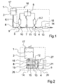
- Fig. 1 the construction of a first embodiment of the device according to the invention for carrying out the method according to the invention is shown.
- the device has a feed pump 3 and a metering pump 4.
- the feed pump 3 is connected via a feed inlet 9 and an inlet pipe 8 to a tank 1.
- the tank 1 contains a liquid paint 2 and may be formed heated.
- the tank 1 is pressure-tight and connected on the opposite side of the inlet line 8 with a pressure source 16.
- a pressure medium for example, air or nitrogen in a free space above the color 2 is admitted within the tank 1, so that a gas cushion 17 is formed.
- the feed pump 3 is connected via a delivery outlet 10 with a delivery line 11 with a metering inlet 12 of the metering pump 4.
- the metering pump 4 is connected via a metering outlet 13 and a metering line 15 with a polymer melt leading guide means (not shown here).
- a return device 14 is arranged within the metering 15.
- the feed pump 3 is driven by the pump drive 6.1 and the metering pump is driven by the pump drive 6.2.
- the control of the pump drives 6.1 and 6.2 via the control device 5.
- the control device 5 is coupled to a pressure sensor 7, which is associated with the delivery line 11 in order to measure a delivery pressure within the delivery line 11.
- the feed pump 3 and the metering pump 4 are driven separately by the pump drives 6.1 and 6.2.
- the pump drive 6.2 of the metering pump 4 is controlled by the control device 5 such that a desired amount of the liquid color through the metering pump 4 is continuously fed via the metering 15 to the leading polymer melt guide. In this case, the liquid ink is fed under a feed pressure in the metering line 15.
- the pump drive 6.1 of the feed pump is controlled by the control device 5 such that the delivery rate of the feed pump 3 generates a predetermined delivery pressure in the delivery line 11.
- the delivery pressure at the metering inlet 12 and the feed pressure at the metering outlet 13 of the metering pump 4 form an optimized for the metering of the ink pressure difference.
- the setting of the pressure difference is influenced and regulated by the setting of the delivery pressure.
- the delivery pressure within the delivery line 11 is detected by the pressure sensor 7 and the control device 5 abandoned.
- the respective actual value of the delivery pressure is compared with a stored in the control device 5 or set target value of the delivery pressure. In the event that a deviation between the target value and the actual value of the delivery pressure is detected, the control device 5 generates a corresponding control signal for changing the drive speed of the pump drive 6.1 of the feed pump 3.
- the feed pump 3 promotes the color 2 from the Tank 1. For better removal of the color 2 from the tank 1 acts on the liquid level of the color 2, a gas cushion 17 within the tank first
- the return device 14 is disposed within the metering line 15.
- the return device 14 is designed such that a reflux of the polymer melt from the guide means to the metering pump 4 is avoided.
- a color change can be performed without interruption of the coupling to the guide means without further notice.
- starting up or stopping the metering pump 4 and the feed pump 3 can be carried out due to the return device 14 regardless of the melt pressure of the polymer melt.
- the return device 14 could be designed as a check valve, in which a valve seat interact with a movably guided adjusting means.
- the funded by the metering pump 4 color 2 pass unhindered the valve seat.
- the opposite direction of flow is blocked by the actuating means by the actuating means in the valve seat closes.
- the return device 14 could also be designed as a heated pipe section, which is dimensioned in length such that solidifies in the cold state, a refluxing polymer melt within the pipe section.
- the pipe section would be heated only in the event that after solidification of the melt in the pipe section, the flow direction is interrupted in both directions.
- the solidified melt in the pipe section dissolves and can be washed away by the conveyed color of the metering pump 4.
- Fig. 1 shown construction of the device according to the invention can be formed either by individual separate connected via lines aggregates or unite to form a unit.
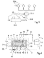
- Fig. 2 is shown schematically a cross-sectional view of another embodiment of a device according to the invention.
- the device consists of a metering pump 4 and a manifold block 26, the a unit 20 are united.
- the distributor block 26 and the metering pump 4 are flanged directly in plate construction.
- the metering pump 4 is designed as a gear pump, with a gear pair 21.
- the gear pair 21 is driven by the pump drive 6 and a drive shaft 27.
- an inlet line 8 is formed, which is connected to the metering inlet 12 of the metering pump 4.
- the inlet line 8 opens into a paint port 18, to which a tank 1 is connected directly.
- a melt terminal 19 is formed on the manifold block 26.
- the melt connection 19 is connected via the metering line 15 to the metering outlet 13 of the metering pump 4.
- a return device 14 in the form of a check valve is formed within the manifold block 26.
- the assembly 20 can be coupled via the melt port 19 through a hose, pipe or a flange with any guide means of a spinning device.
- a section of a spinning device is shown, wherein the possible coupling points 28 are marked to a guide means 23 by a double arrow.
- the polymer melt is first melted by an extruder 23.1.
- the extruder 23.1 this is the polymer in granular form abandoned.
- a melt line 23.2 is arranged, via which the polymer melt is passed to several spinning stations.
- Each of the spinning stations each contains a spinning pump 23.4.
- Fig. 4 For example, four spinning pumps 23.4 are shown.
- an additional dynamic mixer 23.3 is provided in this embodiment.
- the assembly 20 can optionally be attached to one of the coupling points 28.
- the liquid paint could be fed to the melt both in the inlet area and in the outlet area of the extruder 23.1.
- the unit could after Fig. 2 be coupled directly to the melt line 23.2 or to the mixer 23.3 or to the spinning pump 23.4.
- the spinning pump 23.4 is designed as a mixing pump with integrated mixer.
- a further embodiment of the device according to the invention is shown schematically in a cross-sectional view.
- the feed pump 3 and the metering pump 4 are arranged to form a unit 20.
- the feed pump 3 and the metering pump 4 are flanged to two sides of a manifold block 26 for this purpose.
- the feed pump 3 contains a gear set 22 and the metering pump 4 the gear set 21.
- the gear set 21 and the gear set 22 are together via a drive shaft 27 and the pump drive. 6 driven.
- the drive shaft 27 penetrates the distributor block 26.
- On the underside of the distributor block 26 of the paint connection 18 is formed, which is connected via an inlet line 8 in the manifold block 26 with the delivery inlet 9 of the feed pump 3.
- the paint connection 18 is connected to the tank 1 via a pipe or a hose.
- the Schmlezean connection 19 is arranged on the underside of the distributor block 26.
- the melt connection 19 is connected through the metering line 15 with the metering outlet 13 of the metering pump 4.
- the delivery outlet 10 of the feed pump 3 and the metering inlet 12 of the metering pump 4 are connected by a delivery line 11 within the manifold block 26 with each other.
- a return port 29 is connected on the delivery line 11.
- the return port 29 is connected to a bypass line 25, in which a pressure control valve 24 is arranged.
- the bypass line 25 connects the Return port 29 to the tank 1.
- the feed pump 3 and the metering pump 4 are driven together by the pump drive 6.
- the gear set 22 of the feed pump 3 is selected in comparison to the gear set 21 of the metering pump 4 such that the feed pump 3 delivers a larger flow than the metering pump 4.
- the driven gear set 22, the liquid color from the tank 1 is conveyed into the feed line 11 ,
- the liquid color in the delivery line 11 is passed through the metering pump 4 with metered amount to the melt port 19.
- the prevailing in the delivery line 11 delivery pressure is determined by the pressure control valve 24.
- the pressure control valve 24 and the bypass line 25 is arranged separately outside the unit.
- the pressure regulating valve and the bypass line could be integrated within the distributor block 26, wherein the bypass line establishes a connection between the delivery line 11 and the delivery inlet 9 of the delivery pump 3.
- the return device 14 is disposed outside of the manifold block 26 directly to the melt port 19.
- the return device 14 is in this case formed by a pipe section and a heater. In the event that the feed pump 3 and the metering pump 4 are depressurized, a flowing back melt stream within the pipe section of the return device 14 will solidify.
- the reflux to the metering pump 4 is interrupted.
- the heating device of the return device 14 is activated.
- the return device 14 could also be arranged in the illustrated embodiment within the manifold block 26 between the melt port 19 and the Dosierauslledge 13.
- melt-carrying components can be performed heatable.
- other liquid additives may advantageously be added to the melt instead of the liquid color.
Landscapes
- Engineering & Computer Science (AREA)
- Mechanical Engineering (AREA)
- General Engineering & Computer Science (AREA)
- Textile Engineering (AREA)
- Processing And Handling Of Plastics And Other Materials For Molding In General (AREA)
- Spinning Methods And Devices For Manufacturing Artificial Fibers (AREA)
- Coating Apparatus (AREA)
- Processes Of Treating Macromolecular Substances (AREA)
- Polymerisation Methods In General (AREA)
- Treatment Of Fiber Materials (AREA)
Description
- Die Erfindung betrifft eine Vorrichtung zum Einspeisen einer flüssigen Farbe in eine Polymerschmelze gemäß dem Oberbegriff des Anspruchs 1 sowie ein Verfahren zum Einspeisen einer flüssigen Farbe in eine Polymerschmelze gemäß dem Oberbegriff des Anspruchs 15.
- Eine gattungsgemäße Vorrichtung sowie ein gattungsgemäßes Verfahren ist aus der
DE 199 56 251 A1 bekannt. - Aus der
US 6,232,371 B1 ist ein dispersiver Zusatz für ein polymeres, schmelzspinnbares, thermoplastisches Trägermaterial bekannt. Weiterhin beschreibt diese Druckschrift ein Verfahren zur Herstellung eines solchen Werkstoffes und ein Verfahren zur Herstellung eines thermoplastischen Polymerkomposits, welches ein solches Additiv beinhaltet. - Aus der
GB 1 311 162 - Weiterhin ist aus der
US 3,023 764 ein System zum Mischen von Flüssigkeiten bekannt, mit dem ein konstantes Verhältnis eines Additivs in eine filamentbildende Spinnlösung eindosierbar ist, wobei der Strom der Spinnlösung variabel ist. - Schließlich zeigt die
US 4,221,692 ein Verfahren, bei dem ein Additiv in eingeschmolzenes Polymer eingeleitet wird und anschließend eine Homogenisierung durchgeführt wird. Ein Teil des homogenisierten Materials wird danach in einem weiteren Verarbeitungsprozess zugeführt und ein anderer Teil rezykliert und mit Polymer- oder Additivmengen vermengt, die dem Homogenierungsprozess noch nicht unterzogen worden sind. - Um beim Schmelzspinnen synthetischer Fäden eine Einfärbung der Polymerschmelze zu erhalten, wird bei der bekannten Vorrichtung eine flüssige Farbe der Polymerschmelze zugefügt und anschließend vermischt. Hierzu ist die flüssige Farbe in einem Tank gespeichert. An dem Tank ist eine Dosierpumpe angeschlossen. Dosierpumpe ist über eine Leitung mit einer die Polymerschmelze fördernde Spinnpumpe verbunden. Der Spinnpumpe wird über einen Extruder die Polymerschmelze zugeführt. Zum Einfärben der Polymerschmelze wird die flüssige Farbe in dosierter Menge durch die Dosierpumpe der Polymerschmelze aufgegeben. Um eine gleichmäßige und über die Zeit konstante Einfärbung der Polymerschmelze zu erhalten, ist es Voraussetzung, dass die flüssige Farbe exakt in ihrer Menge kontinuierlich der Polymerschmelze zugeführt wird. Bei der bekannten Vorrichtung tritt jedoch das Problem auf, dass die Dosierpumpe eine Druckdifferenz zwischen der drucklos gehaltenen flüssigen Farbe und der unter einem Überdruck geführten Schmelze überbrücken muss. So wird beispielsweise die Polymerschmelze am Ausgang eines Extruders unter einem Überdruck von ca. 100 bar geführt. Damit treten in der Dosierpumpe jedoch verstärkt volumetrische Verluste auf, die eine Mengeneinstellung zur Dosierung der Farbe negativ beeinflussen. Ein weiteres Problem bei der bekannten Vorrichtung liegt darin, dass durch die unmittelbare Anbindung zwischen der Spinnpumpe und der Dosierpumpe eine unter Druck stehende Polymerschmelze unmittelbar bei drucklos gehaltener Dosierpumpe abfließt.
- Es ist nun Aufgabe der Erfindung, eine Vorrichtung der eingangs genannten Art sowie ein Verfahren der eingangs genannten Art derart weiterzubilden, dass eine flüssige Farbe mit möglichst großer Dosiergenauigkeit einer Polymerschmelze zugeführt werden kann.
- Ein weiteres Ziel der Erfindung ist es, eine gattungsgemäße Vorrichtung zu schaffen, die mit hoher Flexibilität an einer Spinnvorrichtung oder einer anderen schmelzeführenden Einrichtung adaptierbar ist, um eine flüssige Farbe oder flüssigen Additive einzuspeisen.
- Die der Erfindung zugrunde liegende Aufgabe wird durch eine Vorrichtung mit den Merkmalen nach Anspruch 1 sowie durch ein Verfahren mit den Merkmalen nach Anspruch 15 gelöst.
- Vorteilhafte Weiterbildungen der Erfindung sind in den Merkmalen und Merkmalskombinationen der jeweiligen Unteransprüche definiert.
- Der besondere Vorteil der Erfindung liegt darin, dass eine flüssige Farbe an jeder beliebigen Position innerhalb der schmelzeführenden Bauteile einer Spinnvorrichtung oder einer anderen schmelzeführenden Einrichtung dosiert mit größtmöglicher Mengengenauigkeit der Polymerschmelze zugeführt werden kann. Insbesondere an den Stellen, an denen die Polymerschmelze unter einem hohen Überdruck durch ein Führungsmittel geführt wird, ist das sichere und genaue Einbringen einer Farbe problemlos durch die Erfindung ausführbar. Hierzu ist der Dosiereinlaß der Dosierpumpe mit einem Förderauslaß einer Förderpumpe verbunden, die ihrerseits über einen Fördereinlaß mit dem Tank verbunden ist. Insoweit liegt ein Vorteil der Erfindung darin, dass zwischen den Funktionen "Farbe fördern" und "Farbe dosieren" getrennt wird. Dabei wird durch die Förderpumpe die flüssige Farbe aus dem Tank entnommen und unter Druck der Dosierpumpe zugeführt. Durch entsprechende Druckeinstellungen am Dosiereinlaß der Dosierpumpe können minimale Druckdifferenzen eingestellt werden, so dass sehr geringe volumetrische Verluste beim Dosieren der flüssigen Farbe mittels der Dosierpumpe auftreten.
- Um die Entnahme der flüssigen Farbe aus dem Tank zu verbessern, wird gemäß der Erfindung vorgeschlagen, dass der Tank mit einer Druckquelle verbunden ist, durch welche ein auf die im Tank gespeicherte Farbe einwirkendes Gaspolster erzeugbar ist. Als Gas sind hierbei Luft oder Stickstoff besonders geeignet. Dabei ist es unabhängig davon, ob der Tank unmittelbar Bestandteil der Baueinheit ist oder separat aufgestellt und über Leitungen mit der Dosierpumpe oder der Förderpumpe verbunden ist.
- Um möglichst die Fördermenge der Förderpumpe mit der Dosiermenge der Dosierpumpe anzugleichen, ist gemäß einer vorteilhaften Weiterbildung der Erfindung der Dosierpumpe und der Förderpumpe jeweils ein steuerbarer Pumpenantrieb zugeordnet. Die Pumpenantriebe werden über eine Steuereinrichtung separat angesteuert.
- Dabei wird die Druckeinstellung eines Förderdruckes am Dosiereinlaß der Dosierpumpe vorteilhaft dadurch überwacht und eingestellt, indem ein Drucksensor zwischen dem Förderauslaß der Förderpumpe und dem Dosiereinlaß der Dosierpumpe angeordnet ist. Der Drucksensor ist über eine Signalleitung mit der Steuereinrichtung verbunden, so dass innerhalb der Steuereinrichtung ein Ist/Soll-Vergleich ausführbar ist und bei einer Abweichung eine entsprechende Korrektur in der Steuerung der Förderpumpe unmittelbar ausführbar ist.
- Um den Regel- und Steuerungsaufwand möglichst gering zu halten, läßt sich die Dosierpumpe und die Förderpumpe jedoch auch vorteilhaft durch einen gemeinsamen Pumpenantrieb antreiben. Um sicherzustellen, dass ein Druck zwischen der Förderpumpe und der Dosierpumpe aufgebaut werden kann, ist die Förderpumpe gegenüber der Dosierpumpe mit einem größeren Fördervolumen ausgestattet. Somit läßt sich auch bei gleicher Antriebsdrehzahl der beiden Pumpen ein Überschuß beim Fördern der flüssigen Farbe erreichen.
- Da bei einer Überschußförderung der Förderdruck auf dem Niveau eines Sollwertes gehalten werden muss, ist gemäß einer vorteilhaften Weiterbildung der Erfindung der Förderauslaß der Förderpumpe durch eine Förderleitung mit dem Dosiereinlaß der Dosierpumpe verbunden. Dabei ist die Förderleitung über ein Druckstellventil mit einer Bypassleitung gekoppelt. Durch das Druckstellventil läßt sich somit ein Sollwert des Förderdruckes innerhalb der Förderleitung einstellen. Bei Drucküberschreitung des Sollwertes wird ein Teil der flüssigen Farbe aus der Förderleitung über das Druckstellventil und die Bypassleitung abgeführt.
- Die Bypassleitung ist vorteilhaft unmittelbar mit dem Tank oder mit dem Fördereinlaß der Förderpumpe gekoppelt, so dass keine Verluste an flüssiger Farbe auftreten.
- Die Erfindung gemäß Anspruch 12 bietet den besonderen Vorteil, eine besonders zur Einspeisung der flüssigen Farbe geeignete Position innerhalb der Spinnvorrichtung oder einer anderen schmelzeführenden Einrichtung auswählen zu können. Hierzu ist die Dosierpumpe als eine Baueinheit mit einem dem Dosierauslaß zugeordneten Schmelzeanschluß und mit einem dem Dosiereinlaß zugeordneten Farbanschluß ausgebildet. Die Baueinheit ist durch den Schmelzeanschluß wahlweise an einem von mehreren Führungsmitteln einer Spinnvorrichtung oder einer anderen schmelzeführenden Einrichtung anschließbar. Damit läßt sich bereits bei Verwendung einer einfachen Dosierpumpe eine hinreichend genaue Beimengung der flüssigen Farbe in die Polymerschmelze erreichen.
- Bei einer besonders bevorzugten Weiterbildung der Erfindung ist dem Dosierauslaß der Dosierpumpe eine Rücklaufeinrichtung zugeordnet, durch welche ein Rückfluß der Polymerschmelze aus dem Schmelzeanschluß in den Dosierauslaß verhindert wird. Damit sind Prozeßabläufe, Ankopplungen und separate Abschaltungen der Dosierpumpe möglich ohne das ein unzulässiges Abführen der Polymerschmelze eintritt.
- Die Rücklaufeinrichtung kann vorteilhaft durch ein Rückschlagventil oder ein Einfrierventil gebildet sein. Bei einem Einfrierventil würde bereits ein beheiztes Rohrstück ausreichen, dessen Länge derart bemessen ist, dass eine zurückfließende Polymerschmelze innerhalb des unbeheizten Rohrstückes erstarrt. Zum Lösen der Rücklaufeinrichtung würde in diesem Fall das Rohrstück beheizt. Eine sichere und schnell wirksame Rücklaufeinrichtung kann vorteilhaft auch durch ein Rückschlagventil erfolgen, welches nur den Durchfluß der flüssigen Farbe zuläßt.
- Um die Entnahme der flüssigen Farbe aus dem Tank zu verbessern, wird gemäß einer vorteilhaften Weiterbildung der Erfindung vorgeschlagen, dass der Tank mit einer Druckquelle verbunden ist, durch welche ein auf die im Tank gespeicherte Farbe einwirkendes Gaspolster erzeugbar ist. Als Gas sind hierbei Luft oder Stickstoff besonders geeignet. Dabei ist es unabhängig davon, ob der Tank unmittelbar Bestandteil der Baueinheit ist oder separat aufgestellt und über Leitungen mit der Dosierpumpe oder der Förderpumpe verbunden ist.
- Grundsätzlich können alle die flüssige Farbe führenden Bauteile beheizbar ausgebildet sein, um insbesondere auch hochviskose Farben einspeisen zu können. So lassen sich Baueinheiten sowie angeschlossene Schläuche beheizbar ausbilden.
- Das erfindungsgemäße Verfahren zeichnet sich insbesondere dadurch aus, dass die flüssige Farbe in vorbestimmter Menge ohne wesentliche Schwankungen in der Dosierung der Polymerschmelze beigemengt werden kann. Das erfindungsgemäße Verfahren ist dabei besonders geeignet, um eine flüssige Farbe möglichst kurz vor dem Schmelzspinnen oder Extrudieren der Polymerschmelze beispielweise zu synthetischen Fasern beizumengen. Dabei wird die flüssige Farbe mittels einer Förderpumpe aus dem Tank gefördert und unter einem Förderdruck der Dosierpumpe zugeführt. An der Dosierpumpe wirkt somit eine Druckdifferenz, die in Abhängigkeit von dem Einspeisedruck in der Dosierpumpe und dem Förderdruck der Förderpumpe ist. Zusätzlich wird durch Verbinden mit einer Druckquelle ein Gaspolster erzeugt, welches auf die im Tank gespeicherte Farbe einwirkt.
- Um möglichst geringe volumetrische Verluste beim Dosieren der flüssigen Farbe zu erhalten, ist der Förderdruck der flüssigen Farbe am Dosiereinlaß der Dosierpumpe vorteilhaft gleich oder kleiner als der Einspeisedruck der flüssigen Farbe am Dosierauslaß der Dosierpumpe eingestellt. Es ist jedoch auch möglich einen etwas größeren Förderdruck einzustellen, entscheidend ist nur das Vorherrschen eines Differenzdruckes.
- Das Zusammenwirken der Förderpumpe und der Dosierpumpe kann dabei nach zwei alternativen Verfahrensvarianten ausgeführt sein. Bei einer ersten Verfahrensvariante wird das Fördervolumen der Förderpumpe derart geregelt, dass der Förderdruck der flüssigen Farbe am Dosiereinlaß der Dosierpumpe im wesentlichen konstant ist. Diese Verfahrensvariante zeichnet sich durch eine hohe Flexibilität und Einstellbarkeit aus.
- Bei einer alternativen Variante ist das Fördervolumen der Förderpumpe größer gewählt, als das Fördervolumen der Dosierpumpe. Damit wird bei gleicher Antriebsdrehzahl der Förderpumpe und der Dosierpumpe ein Überschuß gefördert, so dass der Förderdruck sich über eine einfache Druckeinstellung und Abführung überschüssiger Farbe einstellen läßt. Diese Variante zeichnet sich durch den geringen Antriebs- und Steuerungsaufwand besonders aus.
- Das erfindungsgemäße Verfahren wird nachfolgend anhand einiger Ausführungsbeispiele der erfindungsgemäßen Vorrichtung unter Hinweis auf die beigefügten Zeichnungen näher beschrieben.
- Es stellen dar:
- Fig. 1
- schematisch der Aufbau eines ersten Ausführungsbeispiels der erfindungsgemäßen Vorrichtung
- Fig. 2
- schematisch eine Querschnittsansicht eines weiteren Ausführungsbeispiels der erfindungsgemäßen Vorrichtung
- Fig. 3
- schematisch eine Ansicht eines Ausschnitts einer Spinnvorrichtung
- Fig. 4
- schematisch eine Querschnittsansicht eines weiteren Ausführungsbeispiels der erfindungsgemäßen Vorrichtung.
- In
Fig. 1 ist der Aufbau eines ersten Ausführungsbeispiels der erfindungsgemäßen Vorrichtung zur Durchführung des erfindungsgemäßen Verfahrens gezeigt. - Die Vorrichtung weist eine Förderpumpe 3 und eine Dosierpumpe 4 auf. Die Förderpumpe 3 ist über einen Fördereinlaß 9 und eine Einlaßleitung 8 mit einem Tank 1 verbunden. Der Tank 1 enthält eine flüssige Farbe 2 und kann beheizbar ausgebildet sein. Der Tank 1 ist druckdicht ausgebildet und auf der gegenüberliegenden Seite der Einlaßleitung 8 mit einer Druckquelle 16 verbunden. Durch die Druckquelle 16 wird ein Druckmedium beispielsweise Luft-oder Stickstoff in einem freien Raum oberhalb der Farbe 2 innerhalb des Tanks 1 eingelassen, so dass sich ein Gaspolster 17 ausbildet.
- Die Förderpumpe 3 ist über einen Förderauslaß 10 mit einer Förderleitung 11 mit einem Dosiereinlaß 12 der Dosierpumpe 4 verbunden. Die Dosierpumpe 4 ist über eine Dosierauslaß 13 und eine Dosierleitung 15 mit einem eine Polymerschmelze führenden Führungsmittel (hier nicht dargestellt) verbunden. Innerhalb der Dosierleitung 15 ist eine Rücklaufeinrichtung 14 angeordnet.
- Die Förderpumpe 3 wird durch den Pumpenantrieb 6.1 und die Dosierpumpe wird durch den Pumpenantrieb 6.2 angetrieben. Die Ansteuerung der Pumpenantriebe 6.1 und 6.2 erfolgt über die Steuereinrichtung 5. Die Steuereinrichtung 5 ist mit einem Drucksensor 7 gekoppelt, welcher der Förderleitung 11 zugeordnet ist, um einen Förderdruck innerhalb der Förderleitung 11 zu messen.
- Um die flüssige Farbe 2 aus dem Tank 1 einer Polymerschmelze innerhalb eines Führungsmittels dosiert beizumengen, werden die Förderpumpe 3 und die Dosierpumpe 4 separat durch die Pumpenantriebe 6.1 und 6.2 angetrieben. Der Pumpenantrieb 6.2 der Dosierpumpe 4 wird durch die Steuereinrichtung 5 derart gesteuert, dass eine gewünschte Menge der flüssigen Farbe durch die Dosierpumpe 4 kontinuierlich über die Dosierleitung 15 dem die Polymerschmelze führenden Führungsmittel zugeleitet wird. Hierbei wird die flüssige Farbe unter einem Einspeisedruck in der Dosierleitung 15 geführt. Um die volumetrischen Verluste innerhalb der Dosierpumpe 6.2 möglichst gering zu halten, wird der Pumpenantrieb 6.1 der Förderpumpe durch die Steuereinrichtung 5 derart gesteuert, dass die Fördermenge der Förderpumpe 3 einen vorbestimmten Förderdruck in der Förderleitung 11 erzeugt. Der Förderdruck am Dosiereinlaß 12 und der Einspeisedruck am Dosierauslaß 13 der Dosierpumpe 4 bilden einen für die Dosierung der Farbe optimierte Druckdifferenz. Die Einstellung der Druckdifferenz wird durch die Einstellung des Förderdruckes beeinflußt und geregelt. Der Förderdruck innerhalb der Förderleitung 11 wird durch den Drucksensor 7 erfaßt und der Steuereinrichtung 5 aufgegeben. Innerhalb der Steuereinrichtung 5 wird der jeweilige Ist-Wert des Förderdruckes mit einem in der Steuereinrichtung 5 hinterlegten oder eingestellten Soll-Wert des Förderdruckes verglichen. Für den Fall, dass eine Abweichung zwischen dem Soll-Wert und dem Ist-Wert des Förderdruckes festgestellt wird, erzeugt die Steuereinrichtung 5 ein entsprechendes Steuersignal zur Änderung der Antriebsdrehzahl des Pumpenantriebes 6.1 der Förderpumpe 3. Die Förderpumpe 3 fördert dabei die Farbe 2 aus dem Tank 1. Zur besseren Entnahme der Farbe 2 aus dem Tank 1 wirkt auf dem Flüssigkeitsspiegel der Farbe 2 ein Gaspolster 17 innerhalb des Tanks 1.
- Zwischen der Dosierpumpe 4 und dem nicht dargestellten Führungsmittel ist innerhalb der Dosierleitung 15 die Rücklaufeinrichtung 14 angeordnet. Die Rücklaufeinrichtung 14 ist derart ausgebildet, dass ein Rückfluß der Polymerschmelze aus dem Führungsmittel zur Dosierpumpe 4 vermieden wird. So läßt sich beispielsweise ein Farbwechsel ohne weiteres ohne Unterbrechung der Ankopplung zu dem Führungsmittel ausführen. Auch das Anfahren oder Abstellen der Dosierpumpe 4 und der Förderpumpe 3 können aufgrund der Rücklaufeinrichtung 14 ungeachtet des Schmelzedruckes der Polymerschmelze erfolgen.
- Die Rücklaufeinrichtung 14 könnte dabei als ein Rückschlagventil ausgebildet sein, bei welcher ein Ventilsitz mit einem beweglich geführten Stellmittel zusammenwirken. Dabei wird die durch die Dosierpumpe 4 geförderte Farbe 2 ungehindert den Ventilsitz passieren. Die entgegengesetzte Flußrichtung wird jedoch durch das Stellmittel versperrt, indem das Stellmittel im Ventilsitz schließt. Die Rücklaufeinrichtung 14 könnte jedoch auch als ein beheiztes Rohrstück ausgebildet sein, welches in der Länge derart bemessen ist, dass im kalten Zustand eine rückfließende Polymerschmelze innerhalb des Rohrstückes erstarrt. Das Rohrstück würde nur für den Fall, dass nach Erstarrung der Schmelze in dem Rohrstück die Durchflußrichtung in beiden Richtungen unterbrochen ist, erhitzt. Die erstarrte Schmelze in dem Rohrstück löst sich und läßt sich durch die geförderte Farbe der Dosierpumpe 4 wegspülen.
- Der in
Fig. 1 gezeigte Aufbau der erfindungsgemäßen Vorrichtung läßt sich sowohl durch einzelne separate über Leitungen verbundene Aggregate ausbilden oder zu einer Baueinheit vereinigen. - In
Fig. 2 ist schematisch eine Querschnittsansicht eines weiteren Ausführungsbeispiels einer erfindungsgemäßen Vorrichtung gezeigt. Hierbei sind die Bauteile gleicher Funktion mit identischen Bezugszeichen versehen. Die Vorrichtung besteht aus einer Dosierpumpe 4 und einem Verteilerblock 26, die zu einer Baueinheit 20 vereint sind. Der Verteilerblock 26 und die Dosierpumpe 4 sind in Plattenbauweise unmittelbar aneinandergeflanscht. Die Dosierpumpe 4 ist als eine Zahnradpumpe ausgebildet, mit einem Zahnradpaar 21. Das Zahnradpaar 21 wird über den Pumpenantrieb 6 und eine Antriebswelle 27 angetrieben. - Innerhalb des Verteilerblockes 26 ist eine Einlaßleitung 8 ausgebildet, die mit dem Dosiereinlaß 12 der Dosierpumpe 4 verbunden ist. Die Einlaßleitung 8 mündet in einen Farbanschluß 18, an welchem unmittelbar ein Tank 1 angeschlossen ist. Seitlich versetzt zu dem Farbanschluß 18 ist an dem Verteilerblock 26 ein Schmelzeanschluß 19 ausgebildet. Der Schmelzeanschluß 19 ist über die Dosierleitung 15 mit dem Dosierauslaß 13 der Dosierpumpe 4 verbunden. In der Dosierleitung 15 ist innerhalb des Verteilerblockes 26 eine Rücklaufeinrichtung 14 in Form eines Rückschlagventils ausgebildet.
- Die Baueinheit 20 läßt sich über den Schmelzeanschluß 19 durch eine Schlauchleitung, Rohrleitung oder eine Flanschverbindung mit einem beliebigen Führungsmittel einer Spinnvorrichtung koppeln. In
Fig. 3 ist ein Ausschnitt einer Spinnvorrichtung dargestellt, wobei die möglichen Kopplungsstellen 28 zu einem Führungsmittel 23 durch jeweils einen Doppelpfeil gekennzeichnet sind. In der Spinnvorrichtung wird die Polymerschmelze zunächst durch einen Extruder 23.1 aufgeschmolzen. Dem Extruder 23.1 wird hierzu das Polymer in Granulatform aufgegeben. Auf der Auslaßseite des Extruders 23.1 ist eine Schmelzeleitung 23.2 angeordnet, über die die Polymerschmelze zu mehreren Spinnstellen geführt wird. Jede der Spinnstellen enthält jeweils eine Spinnpumpe 23.4. InFig. 4 sind beispielhaft vier Spinnpumpen 23.4 dargestellt. In der Schmelzeleitung 23.2 ist bei diesem Ausführungsbeispiel ein zusätzlicher dynamischer Mischer 23.3 vorgesehen. Um ein Einfärben des Polymers durch eine Flüssigfarbe ausführen zu können, läßt sich die Baueinheit 20 wahlweise an einer der Kopplungsstellen 28 anbringen. So könnte die flüssige Farbe sowohl im Eingangsbereich als auch im Austrittsbereich des Extruders 23.1 der Schmelze zugeführt werden. Vorteilhaft wird die flüssige Farbe jedoch unmittelbar hinter dem Extruder 23.1 der Polymerschmelze zugeführt. Hierbei könnte die Baueinheit nachFig. 2 unmittelbar an die Schmelzeleitung 23.2 oder an die Mischer 23.3 oder an die Spinnpumpe 23.4 gekoppelt werden. Zweckmäßigerweise wird die Spinnpumpe 23.4 dabei als Mischpumpe mit integriertem Mischer ausgeführt. - In
Fig. 4 ist ein weiteres Ausführungsbeispiel der erfindungsgemäßen Vorrichtung schematisch in einer Querschnittsansicht dargestellt. Bei diesem Ausführungsbeispiel sind die Förderpumpe 3 und die Dosierpumpe 4 zu einer Baueinheit 20 angeordnet. Die Förderpumpe 3 und die Dosierpumpe 4 sind hierzu an zwei Seiten eines Verteilerblockes 26 angeflanscht. Auf der linken Seite befindet sich die Dosierpumpe 4 und auf der rechten Seite die Förderpumpe 3. Die Förderpumpe 3 enthält einen Zahnradsatz 22 und die Dosierpumpe 4 den Zahnradsatz 21. Der Zahnradsatz 21 und der Zahnradsatz 22 werden gemeinsam über eine Antriebswelle 27 und den Pumpenantrieb 6 angetrieben. Hierzu durchdringt die Antriebswelle 27 den Verteilerblock 26. Auf der Unterseite des Verteilerblocks 26 ist der Farbanschluß 18 ausgebildet, der über eine Einlaßleitung 8 in den Verteilerblock 26 mit dem Fördereinlaß 9 der Förderpumpe 3 verbunden ist. Der Farbanschluß 18 ist über ein Rohr oder einen Schlauch mit dem Tank 1 verbunden. - Neben dem Farbanschluß 18 ist an der Unterseite des Verteilerblockes 26 der Schmlezeanschluß 19 angeordnet. Der Schmelzeanschluß 19 ist durch die Dosierleitung 15 mit dem Dosierauslaß 13 der Dosierpumpe 4 verbunden.
- Der Förderauslaß 10 der Förderpumpe 3 und der Dosiereinlaß 12 der Dosierpumpe 4 sind durch eine Förderleitung 11 innerhalb des Verteilerblocks 26 miteinander verbunden.
- An der Förderleitung 11 ist ein Rücklaufanschluß 29 angeschlossen. Der Rücklaufanschluß 29 ist mit einer Bypassleitung 25 verbunden, in welcher ein Druckstellventil 24 angeordnet ist. Die Bypassleitung 25 verbindet den Rücklaufanschluß 29 mit dem Tank 1. Der Tank 1 ist entsprechend den vorhergehenden Ausführungsbeispielen ausgeführt, so dass auf die vorhergehende Beschreibung Bezug genommen wird.
- Im Betrieb werden die Förderpumpe 3 und die Dosierpumpe 4 gemeinsam durch den Pumpenantrieb 6 angetrieben. Der Zahnradsatz 22 der Förderpumpe 3 ist im Vergleich zu dem Zahnradsatz 21 der Dosierpumpe 4 derart gewählt, dass die Förderpumpe 3 eine größere Fördermenge fördert als die Dosierpumpe 4. Durch den angetriebenen Zahnradsatz 22 wird die flüssige Farbe aus dem Tank 1 in die Förderleitung 11 gefördert. Die flüssige Farbe in der Förderleitung 11 wird durch die Dosierpumpe 4 mit dosierter Menge zum Schmelzeanschluß 19 geführt. Hierbei ist der in der Förderleitung 11 vorherrschende Förderdruck durch das Druckstellventil 24 bestimmt.
- Wird in der Förderleitung 11 ein Grenzwert des Förderdruckes überschritten, so wird ein Teilstrom der flüssigen Farbe über das Druckstellventil 24 und der Bypassleitung 25 zu dem Tank 1 zurückgeführt.
- Bei dem in
Fig. 4 dargestellten Ausführungsbeispiel ist das Druckstellventil 24 und die Bypassleitung 25 außerhalb der Baueinheit separat angeordnet. Grundsätzlich könnte jedoch das Druckstellventil und die Bypassleitung innerhalb des Verteilerblockes 26 integriert sein, wobei die Bypassleitung eine Verbindung zwischen der Förderleitung 11 und dem Fördereinlaß 9 der Förderpumpe 3 herstellt. - Bei dem Ausführungsbeispiel ist die Rücklaufeinrichtung 14 außerhalb des Verteilerblockes 26 unmittelbar am Schmelzeanschluß 19 angeordnet. Die Rücklaufeinrichtung 14 wird hierbei durch ein Rohrstück und einer Heizeinrichtung gebildet. Für den Fall, dass die Förderpumpe 3 und die Dosierpumpe 4 drucklos geschaltet sind, wird ein zurückfließender Schmelzestrom innerhalb des Rohrstückes der Rücklaufeinrichtung 14 erstarren.
- Der Rückfluß zur Dosierpumpe 4 ist damit unterbrochen. Zum Lösen des Schmelzepfropfens in dem Rohrstück wird die Heizeinrichtung der Rücklaufeinrichtung 14 aktiviert.
- Es ist jedoch auch möglich, ein Rückschlagventil als Rücklaufeinrichtung zu verwenden. Hierbei würde das Rückschlagventil durch den Druck der flüssigen Farbe geöffnet.
- Die Rücklaufeinrichtung 14 könnte jedoch auch bei dem dargestellten Ausführungsbeispiel innerhalb des Verteilerblockes 26 zwischen dem Schmelzeanschluß 19 und dem Dosierauslaß 13 angeordnet sein.
- Bei den in den
Figuren 1, 2 und4 dargestellten Ausführungsbeispielen lassen sich alle schmelzeführenden Bauteile beheizbar ausführen. Dadurch besteht die Möglichkeit, auch besonders Hochviskosefarben mit hinreichender Dosiergenauigkeit einer Polymerschmelze beizumengen. Anstelle der flüssigen Farbe können selbstverständlich auch andere flüssige Additive vorteilhaft der Schmelze beigefügt werden. -
- 1
- Tank
- 2
- Farbe
- 3
- Förderpumpe
- 4
- Dosierpumpe
- 5
- Steuereinrichtung
- 6
- Pumpenantrieb
- 6.1
- Pumpenantrieb Förderpumpe
- 6.2
- Pumpenantrieb Dosierpumpe
- 7
- Drucksensor
- 8
- Einlaßleitung
- 9
- Fördereinlaß
- 10
- Förderauslaß
- 11
- Förderleitung
- 12
- Dosiereinlaß
- 13
- Dosierauslaß
- 14
- Rücklaufeinrichtung
- 15
- Dosierleitung
- 16
- Druckquelle
- 17
- Gaspolster
- 18
- Farbanschluß
- 19
- Schmelzeanschluß
- 20
- Baueinheit
- 21
- Zahnradpumpe
- 22
- Zahnradsatz
- 23
- Führungsmittel
- 23.1
- Extruder
- 23.2
- Schmelzeleitung
- 23.3
- Mischer
- 23.4
- Spinnpumpe
- 24
- Druckstellventil
- 25
- Bypassleitung
- 26
- Verteilerblock
- 27
- Antriebswelle
- 28
- Kopplungswelle
- 29
- Rücklaufanschluß
Claims (18)
- Vorrichtung zum Einspeisen einer flüssigen Farbe in eine Polymerschmelze mit einer Dosierpumpe (4), welche einen Dosiereinlaß (12) und einen Dosierauslaß (13) aufweist, wobei der Dosiereinlaß (12) mit einem Tank (1) und der Dosierauslaß (13) mit einem die Polymerschmelze führendes Führungsmittel (23) verbunden sind und wobei durch die Dosierpumpe (4) der Polymerschmelze in dem Führungsmittel (23) die aus dem Tank (1) geförderte Farbe (2) in dosierter Menge zugegeben wird, wobei der Dosiereinlaß (12) der Dosierpumpe (4) mit einem Förderauslaß (10) einer Förderpumpe (3) verbunden ist und die Förderpumpe (3) einen Fördereinlaß (9) zur Verbindung mit dem Tank (1) aufweist, dadurch gekennzeichnet, dass der Tank (1) mit einer Druckquelle (16) verbunden ist, durch welche Druckquelle (16) ein auf die im Tank (1) gespeicherte Farbe (2) einwirkendes Gaspolster (17) erzeugbar ist.
- Vorrichtung nach Anspruch 1, dadurch gekennzeichnet, dass der Dosierpumpe (4) und der Förderpumpe (3) jeweils ein steuerbarer Pumpenantrieb (6.1, 6.2) zugeordnet ist und dass die Pumpenantriebe (6.1, 6.2) mit einer Steuereinrichtung (5) verbunden sind.
- Vorrichtung nach Anspruch 2, dadurch gekennzeichnet, dass ein Drucksensor (7) zwischen dem Förderauslaß (10) der Förderpumpe (3) und dem Dosiereinlaß (12) der Dosierpumpe (4) angeordnet ist und dass der Drucksensor (7) mit der Steuereinrichtung (5) verbunden ist.
- Vorrichtung nach Anspruch 1, dadurch gekennzeichnet, dass der Dosierpumpe (4) und der Förderpumpe (3) ein gemeinsamer Pumpenantrieb (6) zugeordnet ist und dass der Pumpenantrieb (6) mit der Steuereinrichtung (5) verbunden ist.
- Vorrichtung nach Anspruch 4, dadurch gekennzeichnet, dass die Förderpumpe (3) gegenüber der Dosierpumpe (4) ein größeres Fördervolumen aufweist.
- Vorrichtung nach Anspruch 5, dadurch gekennzeichnet, dass der Förderauslaß (10) der Förderpumpe (3) durch eine Förderleitung (11) mit dem Dosiereinlaß (12) der Dosierpumpe (4) verbunden ist und dass die Förderleitung (11) über ein Druckstellventil (24) mit einer Bypassleitung (25) verbunden ist.
- Vorrichtung nach Anspruch 6, dadurch gekennzeichnet, dass die Bypassleitung (25) mit dem Fördereinlaß (9) der Förderpumpe (3) oder mit dem Tank (1) verbundenen ist.
- Vorrichtung nach einem der vorgenannten Ansprüche, dadurch gekennzeichnet, dass dem Dosierauslaß (13) der Dosierpumpe (4) eine Rücklaufeinrichtung (14) zugeordnet ist, durch welche ein Rückfluß der Polymerschmelze aus dem Führungsmittel (23) in den Dosierauslaß (13) verhindert wird.
- Vorrichtung nach Anspruch 8, dadurch gekennzeichnet, dass die Rücklaufeinrichtung (14) durch ein Rückschlagventil oder ein Einfrierventil gebildet ist.
- Vorrichtung nach einem der Ansprüche 1 bis 9, dadurch gekennzeichnet, dass der Tank (1) unmittelbar an dem Fördereinlaß (9) der Förderpumpe (3) installiert ist.
- Vorrichtung nach einem der vorgenannten Ansprüche, dadurch gekennzeichnet, dass die Dosierpumpe (4), die Förderpumpe (3) und die Förderleitung (11) beheizbar ausgebildet sind.
- Vorrichtung nach einem der vorgenannten Ansprüche, dadurch gekennzeichnet, dass die Dosierpumpe (4) als eine Baueinheit (20) mit einem dem Dosierauslaß (13) zugeordneten Schmelzeanschluß (19) und mit einem dem Dosiereinlaß (12) zugeordneten Farbanschluß (18) ausgebildet ist und dass die Baueinheit (20) durch den Schmelzeanschluß (19) wahlweise an einem von mehreren Führungsmittel (23) einer Spinnvorrichtung oder einer schmelzeführenden Einrichtung anschließbar ist.
- Vorrichtung nach Anspruch 12, dadurch gekennzeichnet, dass der Tank (1) als Bestandteil der Baueinheit (20) unmittelbar an dem Farbanschluß (18) angeschlossen ist.
- Vorrichtung nach einem der Ansprüche 12 oder 13, dadurch gekennzeichnet, dass die Baueinheit (20) aus der Dosierpumpe (4) und einer Förderpumpe (3) gebildet ist, wobei der Farbanschluß (18) einem Fördereinlaß (9) der Förderpumpe (3) zugeordnet ist und wobei ein Förderauslaß (10) der Förderpumpe (3) mit dem Dosiereinlaß (12) der Dosierpumpe (3) verbunden ist.
- Verfahren zum Einspeisen einer flüssigen Farbe in eine Polymerschmelze, bei welchem die aus einem Tank geförderte flüssige Farbe mittels einer Dosierpumpe unter einem Einspeisedruck der Polymerschmelze dosiert zugeführt wird, wobei die flüssige Farbe mittels einer Förderpumpe aus dem Tank gefördert und unter einem Förderdruck der Dosierpumpe zugeführt wird, dadurch gekennzeichnet, dass durch Verbinden mit einer Druckquelle (16) ein Gaspolster (17) erzeugt wird, welches auf die im Tank (1) gespeicherte Farbe (2) einwirkt.
- Verfahren nach Anspruch 15, dadurch gekennzeichnet, dass der Förderdruck der flüssigen Farbe am Dosiereinlaß der Dosierpumpe gleich oder kleiner ist als der Einspeisedruck der flüssigen Farbe am Dosierauslaß der Dosierpumpe.
- Verfahren nach Anspruch 15 oder 16, dadurch gekennzeichnet, dass das Fördervolumen der Förderpumpe derart geregelt wird, dass der Förderdruck der flüssigen Farbe am Dosiereinlaß der Dosierpumpe im wesentlichen konstant ist.
- Verfahren nach Anspruch 15 oder 16, dadurch gekennzeichnet, dass das Fördervolumen der Förderpumpe größer ist als das Fördervolumen der Dosierpumpe und dass der Förderdruck der flüssigen Farbe am Dosiereinlaß der Dosierpumpe durch ein Druckstellventil einstellbar ist, wobei die durch die Förderpumpe geförderte überschüssige Farbe separat abgeführt wird.
Applications Claiming Priority (3)
| Application Number | Priority Date | Filing Date | Title |
|---|---|---|---|
| DE10233468 | 2002-07-24 | ||
| DE2002133468 DE10233468A1 (de) | 2002-07-24 | 2002-07-24 | Vorrichtung und Verfahren zum Einspeisen einer flüssigen Farbe in eine Polymerschmelze |
| PCT/EP2003/007435 WO2004013386A2 (de) | 2002-07-24 | 2003-07-09 | Vorrichtung und verfahren zum einspeisen einer flüssigen farbe in eine polymerschmelze |
Publications (2)
| Publication Number | Publication Date |
|---|---|
| EP1558796A2 EP1558796A2 (de) | 2005-08-03 |
| EP1558796B1 true EP1558796B1 (de) | 2008-10-01 |
Family
ID=30128294
Family Applications (1)
| Application Number | Title | Priority Date | Filing Date |
|---|---|---|---|
| EP20030766144 Expired - Lifetime EP1558796B1 (de) | 2002-07-24 | 2003-07-09 | Vorrichtung und verfahren zum einspeisen einer flüssigen farbe in eine polymerschmelze |
Country Status (10)
| Country | Link |
|---|---|
| US (1) | US7278776B2 (de) |
| EP (1) | EP1558796B1 (de) |
| JP (1) | JP2006502314A (de) |
| KR (1) | KR101024515B1 (de) |
| CN (1) | CN100376728C (de) |
| AT (1) | ATE409759T1 (de) |
| AU (1) | AU2003250928A1 (de) |
| DE (2) | DE10233468A1 (de) |
| ES (1) | ES2315536T3 (de) |
| WO (1) | WO2004013386A2 (de) |
Families Citing this family (30)
| Publication number | Priority date | Publication date | Assignee | Title |
|---|---|---|---|---|
| CN1745201A (zh) * | 2003-01-29 | 2006-03-08 | 苏拉有限及两合公司 | 用来纺造有色纤维的装置和方法 |
| US7354190B2 (en) * | 2003-10-30 | 2008-04-08 | Deka Products Limited Partnership | Two-stage mixing system, apparatus, and method |
| WO2005056889A1 (de) * | 2003-12-12 | 2005-06-23 | Saurer Gmbh & Co. Kg | Dosiervorrichtung zur hochdruckeinspeisung eines flüssigen additivs |
| DE102004062042A1 (de) | 2004-12-23 | 2006-07-06 | Gottlieb Binder Gmbh & Co. Kg | Verfahren zum Einfärben einer Trägerbahn |
| US20110081415A1 (en) * | 2005-03-10 | 2011-04-07 | Taisho Pharmaceutical Co., Ltd | Coating apparatus |
| DE102008023807A1 (de) | 2007-06-06 | 2008-12-11 | Oerlikon Textile Gmbh & Co. Kg | Vorrichtung zum Schmelzspinnen einer Mehrzahl von Verbundfäden |
| ATE499463T1 (de) * | 2007-09-13 | 2011-03-15 | Oerlikon Textile Gmbh & Co Kg | Vorrichtung zum dosieren und einspeisen flüssiger stoffe |
| DE102008038328A1 (de) | 2007-09-27 | 2009-04-02 | Oerlikon Textile Gmbh & Co. Kg | Verfahren und Vorrichtung zum Schmelzspinnen einer Mehrzahl einfarbiger Filamente |
| US8490893B2 (en) | 2009-04-07 | 2013-07-23 | 3M Innovative Properties Company | Pump-less toner dispenser |
| US8453891B2 (en) * | 2009-04-07 | 2013-06-04 | 3M Innovative Properties Company | Pump-less toner dispensing cap |
| CN102465350A (zh) * | 2010-11-04 | 2012-05-23 | 泉州市约克颜料有限公司 | 一种色母在线添加熔体纺丝生产方法及装置 |
| EP2961523B1 (de) * | 2013-03-01 | 2019-04-24 | Tetra Laval Holdings & Finance SA | Flüssigkeitsverarbeitungsverfahren |
| CN103215656B (zh) * | 2013-04-26 | 2016-08-31 | 大连合成纤维研究设计院股份有限公司 | 聚酯纤维的溶剂载体纺前原液着色工艺 |
| KR102116102B1 (ko) * | 2013-06-28 | 2020-05-27 | 컬러매트릭스 홀딩즈 아이엔씨. | 폴리머 물질용 펌프 시스템 |
| DE102015001392A1 (de) | 2015-02-04 | 2016-08-04 | Bb Engineering Gmbh | Verfahren und Vorrichtung zum Einspeisen eines Zusatzstoffes in einen Schmelzstrom einer Polymerschmelze |
| DK178818B1 (en) * | 2015-07-06 | 2017-02-27 | Tetra Laval Holdings & Finance | Self adjusting pump for ice cream freezer |
| EP3127429B1 (de) * | 2015-08-05 | 2017-12-13 | Albert Handtmann Maschinenfabrik GmbH & Co. KG | Füllmaschine und verfahren zum abfüllen von pastöser masse, insbesondere zum herstellen von würsten |
| GB201516143D0 (en) | 2015-09-11 | 2015-10-28 | Colormatrix Holdings Inc | Polymeric materials |
| US10294450B2 (en) | 2015-10-09 | 2019-05-21 | Deka Products Limited Partnership | Fluid pumping and bioreactor system |
| GB201609228D0 (en) * | 2016-05-25 | 2016-07-06 | Colormatrix Holdings Inc | Polymeric materials |
| US11299705B2 (en) | 2016-11-07 | 2022-04-12 | Deka Products Limited Partnership | System and method for creating tissue |
| GB201703142D0 (en) * | 2017-02-27 | 2017-04-12 | Colormatrix Holdings Inc | Polymeric materials |
| WO2019175142A1 (de) * | 2018-03-15 | 2019-09-19 | Oerlikon Textile Gmbh & Co. Kg | Vorrichtung zur einspeisung von flüssiger farbe in einen schmelzestrom schmelzeflüssigen polymers |
| USD919045S1 (en) | 2018-09-12 | 2021-05-11 | 3M Innovative Properties Company | Liquid delivery system coupler |
| USD898868S1 (en) | 2018-09-12 | 2020-10-13 | 3M Innovative Properties Company | Liquid delivery system lid |
| USD918339S1 (en) | 2018-09-12 | 2021-05-04 | 3M Innovative Properties Company | Liquid delivery system cup |
| CN110253790A (zh) * | 2019-06-21 | 2019-09-20 | 嵊州摩天自动化设备有限公司 | 一种惰性气体强压式塑料薄膜回收装置 |
| CN111439605A (zh) * | 2020-05-06 | 2020-07-24 | 上海电气电站环保工程有限公司 | 一种容积式计量加料装置 |
| WO2024062336A1 (en) * | 2022-09-21 | 2024-03-28 | Aladdin Manufacturing Corporation | Solution dyed yarn color correction |
| CN118286969B (zh) * | 2024-03-15 | 2025-10-10 | 中钢集团马鞍山矿山研究总院股份有限公司 | 一种防止液态催化剂低温易结晶的全自动添加装置及方法 |
Family Cites Families (20)
| Publication number | Priority date | Publication date | Assignee | Title |
|---|---|---|---|---|
| FR991627A (fr) * | 1944-04-19 | 1951-10-08 | Pompe d'extraction de liquides dans des récipients sans pression | |
| US3023764A (en) * | 1958-04-16 | 1962-03-06 | American Viscose Corp | Liquid blending system |
| GB1311162A (en) * | 1970-07-08 | 1973-03-21 | Slack & Parr Ltd | Means for feeding coloured hot melt polymer to the spinnerets of a spinning machine |
| US3754735A (en) * | 1970-07-08 | 1973-08-28 | Slack & Parr Ltd | Polymer coloration |
| US3754734A (en) * | 1971-07-08 | 1973-08-28 | Slack & Parr Ltd | Coloration of hot melt polymers |
| IT1084547B (it) * | 1977-09-30 | 1985-05-25 | Snia Viscosa | Procedimento ed apparecchiatura per la produzione di polimeri sintetici additivati. |
| US4547128A (en) * | 1984-05-07 | 1985-10-15 | Hayes John W | Proportional mixing means |
| DE4334922C2 (de) * | 1993-10-13 | 1995-08-24 | Rieter Automatik Gmbh | Verfahren zur Herstellung von Fasern aus Polyolefinen |
| JPH0931739A (ja) * | 1995-07-21 | 1997-02-04 | Mitsubishi Rayon Co Ltd | 多錘溶融混合紡糸方法及び多錘溶融混合紡糸装置 |
| US6232371B1 (en) * | 1996-03-04 | 2001-05-15 | Basf Corporation | Dispersible additive systems for polymeric materials, and methods of making and incorporating the same in such polymeric materials |
| EP0837161B1 (de) * | 1996-10-21 | 2002-09-04 | B a r m a g AG | Verfahren und Vorrichtung zum Spinnen von thermoplastischen Fäden |
| ID23632A (id) * | 1998-03-27 | 2000-05-04 | Dow Corning | Metode pengukuran bahan tambahan cair ke dalam bahan yang mengandung silikon cair |
| AT408995B (de) * | 1998-12-01 | 2002-04-25 | Sml Maschinengesellschaft Mbh | Einrichtung zum herstellen künstlicher filamente |
| EP1008750A1 (de) * | 1998-12-07 | 2000-06-14 | Robert Bosch Gmbh | Hydraulisches Kompaktaggregat |
| JP2000205148A (ja) * | 1999-01-11 | 2000-07-25 | Toyota Autom Loom Works Ltd | 多段ル―ツポンプ及び多段ル―ツポンプのロ―タハウジング製作方法 |
| JP3795255B2 (ja) * | 1999-05-21 | 2006-07-12 | 旭貿易株式会社 | 紡糸原料着色装置 |
| US6254363B1 (en) * | 2000-01-20 | 2001-07-03 | M. A. Hannacolor, A Division Of M. A. Hanna Company | Liquid colorant tube assembly |
| DE10022889B4 (de) * | 2000-05-25 | 2007-12-20 | Lurgi Zimmer Gmbh | Verfahren zum Herstellen von synthetischen Fäden aus einer Polymermischung auf Polyesterbasis |
| US7416096B2 (en) * | 2001-01-31 | 2008-08-26 | Maguire Stephen B | Apparatus for supplying liquid color |
| GB0125497D0 (en) * | 2001-10-24 | 2001-12-12 | Colormatrix Europe Ltd | Apparatus and method for delivering fluent colourant material |
-
2002
- 2002-07-24 DE DE2002133468 patent/DE10233468A1/de not_active Withdrawn
-
2003
- 2003-07-09 DE DE50310586T patent/DE50310586D1/de not_active Expired - Lifetime
- 2003-07-09 ES ES03766144T patent/ES2315536T3/es not_active Expired - Lifetime
- 2003-07-09 KR KR1020057001071A patent/KR101024515B1/ko not_active Expired - Fee Related
- 2003-07-09 JP JP2004525172A patent/JP2006502314A/ja active Pending
- 2003-07-09 AT AT03766144T patent/ATE409759T1/de not_active IP Right Cessation
- 2003-07-09 WO PCT/EP2003/007435 patent/WO2004013386A2/de not_active Ceased
- 2003-07-09 CN CNB038176025A patent/CN100376728C/zh not_active Expired - Fee Related
- 2003-07-09 AU AU2003250928A patent/AU2003250928A1/en not_active Abandoned
- 2003-07-09 EP EP20030766144 patent/EP1558796B1/de not_active Expired - Lifetime
-
2005
- 2005-01-21 US US11/040,443 patent/US7278776B2/en not_active Expired - Fee Related
Also Published As
| Publication number | Publication date |
|---|---|
| DE50310586D1 (de) | 2008-11-13 |
| WO2004013386A2 (de) | 2004-02-12 |
| US20050128869A1 (en) | 2005-06-16 |
| KR101024515B1 (ko) | 2011-03-31 |
| US7278776B2 (en) | 2007-10-09 |
| JP2006502314A (ja) | 2006-01-19 |
| DE10233468A1 (de) | 2004-02-12 |
| ES2315536T3 (es) | 2009-04-01 |
| CN1692187A (zh) | 2005-11-02 |
| ATE409759T1 (de) | 2008-10-15 |
| KR20060006757A (ko) | 2006-01-19 |
| AU2003250928A1 (en) | 2004-02-23 |
| EP1558796A2 (de) | 2005-08-03 |
| WO2004013386A3 (de) | 2005-05-26 |
| CN100376728C (zh) | 2008-03-26 |
Similar Documents
| Publication | Publication Date | Title |
|---|---|---|
| EP1558796B1 (de) | Vorrichtung und verfahren zum einspeisen einer flüssigen farbe in eine polymerschmelze | |
| DE69505999T3 (de) | Verfahren und vorrichtung zur herstellung von geschlossen-zelligen schaumprodukten | |
| EP1932423B1 (de) | Spritzeinrichtung | |
| EP2188420B1 (de) | Vorrichtung zum dosieren und einspeisen flüssiger stoffe | |
| DE2933553A1 (de) | Verfahren und einrichtung zum herstellen von formteilen aus einem mehrkomponentenreaktionsgemisch | |
| DE102021121046A1 (de) | Vorrichtung und Verfahren zur Herstellung von Bauwerken oder Objekten aus eingefärbtem Beton | |
| EP3782794A2 (de) | Anlage zur herstellung einer kunststoffschmelze und verwendung einer solchen anlage zur herstellung einer kunststoffschmelze für eine poröse folie | |
| EP1943009B1 (de) | Vorrichtung und verfaheren zum mischen von flüssigfarben sowie verwendung eines solchen verfahrens zum einfärben von kunststoffen | |
| DE1435359A1 (de) | Verfahren und Vorrichtung zum Verteilen von viskosen Fluessigkeiten | |
| DE102007020095A1 (de) | Vorrichtung und Verfahren zum Schaumauftrag auf Substrate mit großer Breite | |
| DE102005042380A1 (de) | Vorrichtung und Verfahren zum Erzeugen eines Schaummaterials | |
| DE102010039025A1 (de) | Plastifiziereinheit für eine Spritzgießmaschine, einen Extruder und dergleichen und dafür vorgesehene Flüssigkeitszuführeinrichtung | |
| DE10136243B4 (de) | Ventilanordnung zur Steuerung der Zudosierung von fluiden Additiven in eine Kunststoffschmelze | |
| DE10223374B4 (de) | Vorrichtung zum universellen Einfärben von kontinuierlich unter Druck strömenden, in einer Plastifiziereinheit plastifizierten viskosen Massen | |
| DE2053646A1 (de) | Maschine zur Verarbeitung Zellen bildender Kunststoffe | |
| EP1902774A1 (de) | Mischvorrichtung, Spritzvorrichtung für den Pflanzenschutz und Verfahren zum Betreiben einer Spritzvorrichtung | |
| DE102009055665A1 (de) | Verfahren und Vorrichtung zum Hochdruckmischen von gefüllten Polyurethanharzen | |
| DE2108759C3 (de) | Verfahren zur kontinuierlichen Herstellung von Formkörpern durch die aktivierte anionische Polymerisation von Laurinlactam | |
| EP2842710B1 (de) | Vorrichtung zum genauen dosieren eines fluidvolumenstroms für eine kunststoffmischung | |
| EP1702738A2 (de) | Verfahren zum kontinuierlichen Herstellen von expandierfähigem Kunststoff-Granulat | |
| EP0179189A2 (de) | Verfahren und Vorrichtung zur Dosierung und Mischung zweier Fluidkomponenten | |
| DE2051568A1 (en) | Molten plastic extrusion - with pressure - controlled recycle system | |
| EP4311642B1 (de) | Vorrichtung zur bereitstellung eines kunststoffes, sowie darauf bezogenes verfahren zum ausdosieren des kunststoffes | |
| DE29623922U1 (de) | Vorrichtung zur Verarbeitung von viskosen Mehrkomponenten-Elastomeren | |
| DE69724493T2 (de) | Einspritzvorrichtung für eine chemische Verbindung, Extruder und Verfahren zum Extrudieren |
Legal Events
| Date | Code | Title | Description |
|---|---|---|---|
| PUAI | Public reference made under article 153(3) epc to a published international application that has entered the european phase |
Free format text: ORIGINAL CODE: 0009012 |
|
| 17P | Request for examination filed |
Effective date: 20050114 |
|
| AK | Designated contracting states |
Kind code of ref document: A2 Designated state(s): AT BE BG CH CY CZ DE DK EE ES FI FR GB GR HU IE IT LI LU MC NL PT RO SE SI SK TR |
|
| AX | Request for extension of the european patent |
Extension state: AL LT LV MK |
|
| DAX | Request for extension of the european patent (deleted) | ||
| 17Q | First examination report despatched |
Effective date: 20060628 |
|
| RAP1 | Party data changed (applicant data changed or rights of an application transferred) |
Owner name: OERLIKON TEXTILE GMBH & CO. KG |
|
| GRAP | Despatch of communication of intention to grant a patent |
Free format text: ORIGINAL CODE: EPIDOSNIGR1 |
|
| RAP1 | Party data changed (applicant data changed or rights of an application transferred) |
Owner name: OERLIKON TEXTILE GMBH & CO. KG |
|
| GRAS | Grant fee paid |
Free format text: ORIGINAL CODE: EPIDOSNIGR3 |
|
| GRAA | (expected) grant |
Free format text: ORIGINAL CODE: 0009210 |
|
| AK | Designated contracting states |
Kind code of ref document: B1 Designated state(s): AT BE BG CH CY CZ DE DK EE ES FI FR GB GR HU IE IT LI LU MC NL PT RO SE SI SK TR |
|
| REG | Reference to a national code |
Ref country code: GB Ref legal event code: FG4D Free format text: NOT ENGLISH |
|
| REG | Reference to a national code |
Ref country code: CH Ref legal event code: EP |
|
| REG | Reference to a national code |
Ref country code: IE Ref legal event code: FG4D Free format text: LANGUAGE OF EP DOCUMENT: GERMAN |
|
| REF | Corresponds to: |
Ref document number: 50310586 Country of ref document: DE Date of ref document: 20081113 Kind code of ref document: P |
|
| PG25 | Lapsed in a contracting state [announced via postgrant information from national office to epo] |
Ref country code: SI Free format text: LAPSE BECAUSE OF FAILURE TO SUBMIT A TRANSLATION OF THE DESCRIPTION OR TO PAY THE FEE WITHIN THE PRESCRIBED TIME-LIMIT Effective date: 20081001 |
|
| REG | Reference to a national code |
Ref country code: ES Ref legal event code: FG2A Ref document number: 2315536 Country of ref document: ES Kind code of ref document: T3 |
|
| REG | Reference to a national code |
Ref country code: IE Ref legal event code: FD4D |
|
| PG25 | Lapsed in a contracting state [announced via postgrant information from national office to epo] |
Ref country code: BG Free format text: LAPSE BECAUSE OF FAILURE TO SUBMIT A TRANSLATION OF THE DESCRIPTION OR TO PAY THE FEE WITHIN THE PRESCRIBED TIME-LIMIT Effective date: 20090101 |
|
| PG25 | Lapsed in a contracting state [announced via postgrant information from national office to epo] |
Ref country code: FI Free format text: LAPSE BECAUSE OF FAILURE TO SUBMIT A TRANSLATION OF THE DESCRIPTION OR TO PAY THE FEE WITHIN THE PRESCRIBED TIME-LIMIT Effective date: 20081001 Ref country code: PT Free format text: LAPSE BECAUSE OF FAILURE TO SUBMIT A TRANSLATION OF THE DESCRIPTION OR TO PAY THE FEE WITHIN THE PRESCRIBED TIME-LIMIT Effective date: 20090302 |
|
| PG25 | Lapsed in a contracting state [announced via postgrant information from national office to epo] |
Ref country code: RO Free format text: LAPSE BECAUSE OF FAILURE TO SUBMIT A TRANSLATION OF THE DESCRIPTION OR TO PAY THE FEE WITHIN THE PRESCRIBED TIME-LIMIT Effective date: 20081001 Ref country code: EE Free format text: LAPSE BECAUSE OF FAILURE TO SUBMIT A TRANSLATION OF THE DESCRIPTION OR TO PAY THE FEE WITHIN THE PRESCRIBED TIME-LIMIT Effective date: 20081001 Ref country code: DK Free format text: LAPSE BECAUSE OF FAILURE TO SUBMIT A TRANSLATION OF THE DESCRIPTION OR TO PAY THE FEE WITHIN THE PRESCRIBED TIME-LIMIT Effective date: 20081001 Ref country code: IE Free format text: LAPSE BECAUSE OF FAILURE TO SUBMIT A TRANSLATION OF THE DESCRIPTION OR TO PAY THE FEE WITHIN THE PRESCRIBED TIME-LIMIT Effective date: 20081001 |
|
| PLBE | No opposition filed within time limit |
Free format text: ORIGINAL CODE: 0009261 |
|
| STAA | Information on the status of an ep patent application or granted ep patent |
Free format text: STATUS: NO OPPOSITION FILED WITHIN TIME LIMIT |
|
| PG25 | Lapsed in a contracting state [announced via postgrant information from national office to epo] |
Ref country code: CZ Free format text: LAPSE BECAUSE OF FAILURE TO SUBMIT A TRANSLATION OF THE DESCRIPTION OR TO PAY THE FEE WITHIN THE PRESCRIBED TIME-LIMIT Effective date: 20081001 Ref country code: SE Free format text: LAPSE BECAUSE OF FAILURE TO SUBMIT A TRANSLATION OF THE DESCRIPTION OR TO PAY THE FEE WITHIN THE PRESCRIBED TIME-LIMIT Effective date: 20090101 |
|
| 26N | No opposition filed |
Effective date: 20090702 |
|
| PG25 | Lapsed in a contracting state [announced via postgrant information from national office to epo] |
Ref country code: SK Free format text: LAPSE BECAUSE OF FAILURE TO SUBMIT A TRANSLATION OF THE DESCRIPTION OR TO PAY THE FEE WITHIN THE PRESCRIBED TIME-LIMIT Effective date: 20081001 |
|
| PGFP | Annual fee paid to national office [announced via postgrant information from national office to epo] |
Ref country code: ES Payment date: 20090707 Year of fee payment: 7 |
|
| PGFP | Annual fee paid to national office [announced via postgrant information from national office to epo] |
Ref country code: NL Payment date: 20090730 Year of fee payment: 7 |
|
| PG25 | Lapsed in a contracting state [announced via postgrant information from national office to epo] |
Ref country code: MC Free format text: LAPSE BECAUSE OF NON-PAYMENT OF DUE FEES Effective date: 20090731 |
|
| REG | Reference to a national code |
Ref country code: FR Ref legal event code: ST Effective date: 20100331 |
|
| PG25 | Lapsed in a contracting state [announced via postgrant information from national office to epo] |
Ref country code: FR Free format text: LAPSE BECAUSE OF NON-PAYMENT OF DUE FEES Effective date: 20090731 |
|
| PG25 | Lapsed in a contracting state [announced via postgrant information from national office to epo] |
Ref country code: GR Free format text: LAPSE BECAUSE OF FAILURE TO SUBMIT A TRANSLATION OF THE DESCRIPTION OR TO PAY THE FEE WITHIN THE PRESCRIBED TIME-LIMIT Effective date: 20090102 |
|
| PG25 | Lapsed in a contracting state [announced via postgrant information from national office to epo] |
Ref country code: AT Free format text: LAPSE BECAUSE OF NON-PAYMENT OF DUE FEES Effective date: 20090709 |
|
| REG | Reference to a national code |
Ref country code: NL Ref legal event code: V1 Effective date: 20110201 |
|
| PG25 | Lapsed in a contracting state [announced via postgrant information from national office to epo] |
Ref country code: LU Free format text: LAPSE BECAUSE OF NON-PAYMENT OF DUE FEES Effective date: 20090709 |
|
| PG25 | Lapsed in a contracting state [announced via postgrant information from national office to epo] |
Ref country code: NL Free format text: LAPSE BECAUSE OF NON-PAYMENT OF DUE FEES Effective date: 20110201 |
|
| PG25 | Lapsed in a contracting state [announced via postgrant information from national office to epo] |
Ref country code: HU Free format text: LAPSE BECAUSE OF FAILURE TO SUBMIT A TRANSLATION OF THE DESCRIPTION OR TO PAY THE FEE WITHIN THE PRESCRIBED TIME-LIMIT Effective date: 20090402 |
|
| REG | Reference to a national code |
Ref country code: ES Ref legal event code: FD2A Effective date: 20110818 |
|
| PG25 | Lapsed in a contracting state [announced via postgrant information from national office to epo] |
Ref country code: CY Free format text: LAPSE BECAUSE OF FAILURE TO SUBMIT A TRANSLATION OF THE DESCRIPTION OR TO PAY THE FEE WITHIN THE PRESCRIBED TIME-LIMIT Effective date: 20081001 |
|
| PGFP | Annual fee paid to national office [announced via postgrant information from national office to epo] |
Ref country code: CH Payment date: 20110714 Year of fee payment: 9 |
|
| PG25 | Lapsed in a contracting state [announced via postgrant information from national office to epo] |
Ref country code: ES Free format text: LAPSE BECAUSE OF NON-PAYMENT OF DUE FEES Effective date: 20100710 |
|
| PGFP | Annual fee paid to national office [announced via postgrant information from national office to epo] |
Ref country code: TR Payment date: 20110711 Year of fee payment: 9 |
|
| REG | Reference to a national code |
Ref country code: CH Ref legal event code: PL |
|
| PG25 | Lapsed in a contracting state [announced via postgrant information from national office to epo] |
Ref country code: LI Free format text: LAPSE BECAUSE OF NON-PAYMENT OF DUE FEES Effective date: 20120731 Ref country code: CH Free format text: LAPSE BECAUSE OF NON-PAYMENT OF DUE FEES Effective date: 20120731 |
|
| PG25 | Lapsed in a contracting state [announced via postgrant information from national office to epo] |
Ref country code: TR Free format text: LAPSE BECAUSE OF NON-PAYMENT OF DUE FEES Effective date: 20120709 |
|
| PGFP | Annual fee paid to national office [announced via postgrant information from national office to epo] |
Ref country code: IT Payment date: 20160729 Year of fee payment: 14 |
|
| PGFP | Annual fee paid to national office [announced via postgrant information from national office to epo] |
Ref country code: BE Payment date: 20160630 Year of fee payment: 14 |
|
| REG | Reference to a national code |
Ref country code: BE Ref legal event code: MM Effective date: 20170731 |
|
| PG25 | Lapsed in a contracting state [announced via postgrant information from national office to epo] |
Ref country code: IT Free format text: LAPSE BECAUSE OF NON-PAYMENT OF DUE FEES Effective date: 20170709 Ref country code: BE Free format text: LAPSE BECAUSE OF NON-PAYMENT OF DUE FEES Effective date: 20170731 |
|
| PGFP | Annual fee paid to national office [announced via postgrant information from national office to epo] |
Ref country code: DE Payment date: 20180730 Year of fee payment: 16 |
|
| PGFP | Annual fee paid to national office [announced via postgrant information from national office to epo] |
Ref country code: GB Payment date: 20180724 Year of fee payment: 16 |
|
| REG | Reference to a national code |
Ref country code: DE Ref legal event code: R119 Ref document number: 50310586 Country of ref document: DE |
|
| GBPC | Gb: european patent ceased through non-payment of renewal fee |
Effective date: 20190709 |
|
| PG25 | Lapsed in a contracting state [announced via postgrant information from national office to epo] |
Ref country code: DE Free format text: LAPSE BECAUSE OF NON-PAYMENT OF DUE FEES Effective date: 20200201 Ref country code: GB Free format text: LAPSE BECAUSE OF NON-PAYMENT OF DUE FEES Effective date: 20190709 |