EP1557628A2 - Echangeur de chaleur, en particulier radiateur de refroidissement ou radiateur d'air de suralimentation pour véhicule - Google Patents
Echangeur de chaleur, en particulier radiateur de refroidissement ou radiateur d'air de suralimentation pour véhicule Download PDFInfo
- Publication number
- EP1557628A2 EP1557628A2 EP20040028831 EP04028831A EP1557628A2 EP 1557628 A2 EP1557628 A2 EP 1557628A2 EP 20040028831 EP20040028831 EP 20040028831 EP 04028831 A EP04028831 A EP 04028831A EP 1557628 A2 EP1557628 A2 EP 1557628A2
- Authority
- EP
- European Patent Office
- Prior art keywords
- heat exchanger
- frame
- pipe ends
- soldered
- exchanger according
- Prior art date
- Legal status (The legal status is an assumption and is not a legal conclusion. Google has not performed a legal analysis and makes no representation as to the accuracy of the status listed.)
- Withdrawn
Links
- 239000000110 cooling liquid Substances 0.000 title 1
- 239000002826 coolant Substances 0.000 claims description 2
- 229910000679 solder Inorganic materials 0.000 abstract description 2
- 230000000717 retained effect Effects 0.000 abstract 1
- 238000005476 soldering Methods 0.000 description 18
- 238000000034 method Methods 0.000 description 6
- 229910052751 metal Inorganic materials 0.000 description 4
- 239000002184 metal Substances 0.000 description 4
- 238000004904 shortening Methods 0.000 description 3
- 238000004519 manufacturing process Methods 0.000 description 2
- 239000000155 melt Substances 0.000 description 2
- 235000011299 Brassica oleracea var botrytis Nutrition 0.000 description 1
- 240000003259 Brassica oleracea var. botrytis Species 0.000 description 1
- 241000196324 Embryophyta Species 0.000 description 1
- 229910052782 aluminium Inorganic materials 0.000 description 1
- XAGFODPZIPBFFR-UHFFFAOYSA-N aluminium Chemical compound [Al] XAGFODPZIPBFFR-UHFFFAOYSA-N 0.000 description 1
- 238000005516 engineering process Methods 0.000 description 1
- 239000002360 explosive Substances 0.000 description 1
- 238000007667 floating Methods 0.000 description 1
- 239000000463 material Substances 0.000 description 1
- 238000007747 plating Methods 0.000 description 1
- 238000007789 sealing Methods 0.000 description 1
Images


Classifications
-
- F—MECHANICAL ENGINEERING; LIGHTING; HEATING; WEAPONS; BLASTING
- F28—HEAT EXCHANGE IN GENERAL
- F28F—DETAILS OF HEAT-EXCHANGE AND HEAT-TRANSFER APPARATUS, OF GENERAL APPLICATION
- F28F9/00—Casings; Header boxes; Auxiliary supports for elements; Auxiliary members within casings
- F28F9/02—Header boxes; End plates
- F28F9/0219—Arrangements for sealing end plates into casing or header box; Header box sub-elements
- F28F9/0221—Header boxes or end plates formed by stacked elements
-
- F—MECHANICAL ENGINEERING; LIGHTING; HEATING; WEAPONS; BLASTING
- F28—HEAT EXCHANGE IN GENERAL
- F28F—DETAILS OF HEAT-EXCHANGE AND HEAT-TRANSFER APPARATUS, OF GENERAL APPLICATION
- F28F9/00—Casings; Header boxes; Auxiliary supports for elements; Auxiliary members within casings
- F28F9/02—Header boxes; End plates
- F28F9/04—Arrangements for sealing elements into header boxes or end plates
- F28F9/16—Arrangements for sealing elements into header boxes or end plates by permanent joints, e.g. by rolling
- F28F9/18—Arrangements for sealing elements into header boxes or end plates by permanent joints, e.g. by rolling by welding
- F28F9/182—Arrangements for sealing elements into header boxes or end plates by permanent joints, e.g. by rolling by welding the heat-exchange conduits having ends with a particular shape, e.g. deformed; the heat-exchange conduits or end plates having supplementary joining means, e.g. abutments
-
- F—MECHANICAL ENGINEERING; LIGHTING; HEATING; WEAPONS; BLASTING
- F28—HEAT EXCHANGE IN GENERAL
- F28D—HEAT-EXCHANGE APPARATUS, NOT PROVIDED FOR IN ANOTHER SUBCLASS, IN WHICH THE HEAT-EXCHANGE MEDIA DO NOT COME INTO DIRECT CONTACT
- F28D21/00—Heat-exchange apparatus not covered by any of the groups F28D1/00 - F28D20/00
- F28D2021/0019—Other heat exchangers for particular applications; Heat exchange systems not otherwise provided for
- F28D2021/008—Other heat exchangers for particular applications; Heat exchange systems not otherwise provided for for vehicles
- F28D2021/0082—Charged air coolers
-
- F—MECHANICAL ENGINEERING; LIGHTING; HEATING; WEAPONS; BLASTING
- F28—HEAT EXCHANGE IN GENERAL
- F28D—HEAT-EXCHANGE APPARATUS, NOT PROVIDED FOR IN ANOTHER SUBCLASS, IN WHICH THE HEAT-EXCHANGE MEDIA DO NOT COME INTO DIRECT CONTACT
- F28D21/00—Heat-exchange apparatus not covered by any of the groups F28D1/00 - F28D20/00
- F28D2021/0019—Other heat exchangers for particular applications; Heat exchange systems not otherwise provided for
- F28D2021/008—Other heat exchangers for particular applications; Heat exchange systems not otherwise provided for for vehicles
- F28D2021/0091—Radiators
- F28D2021/0094—Radiators for recooling the engine coolant
Definitions
- the invention relates to a heat exchanger, in particular a coolant / air or intercooler / air cooler for motor vehicles according to the preamble of claim 1 - known from DE 195 43 986 A1 (Fig. 10) of Applicant.
- FIG. 10 is a collecting container made of die-cast or plastic, which does not directly with the tube ends, but by means of an additional metallic so-called end piece connected is, which in turn is soldered to the narrow sides of the pipe ends.
- the collection box is mechanical with the extension, z. B. over a Flare connected and sealed by an inserted seal.
- This alternative according to FIG. 10 is thus not a sorted heat exchanger, However, it can be compared to this in certain applications of Be an advantage.
- Blocks which are cassetted before soldering and then tensioned, is a shortening of the block dimension during soldering.
- the flat tubes and / or corrugated fins are coated with a solder plating, which during soldering melts, so that the entire heat exchanger block (Network) sets.
- This shortening of the block dimension must be at the connection be taken into account between pipe ends and collecting tank.
- so-called Floating side panels proposed which shortening of the heat exchanger block, d. H. can follow the setting movement.
- a closed rectangular frame for holding the flared pipe ends provided, wherein between the outermost pipe ends and side frames are inserted into the frame.
- these side pieces are slidably arranged in the frame so that they can be used during the soldering operation of the setting movement of the heat exchanger block, d. H. can follow the network.
- This will be the advantage of a safe and dense Soldering of the pipe ends achieved in the rectangular frame and beyond also a complete soldering of the corrugated fins with the flat tubes of the Heat exchanger block.
- On this finished soldered unit, consisting of Ribs / tube block and frame, can then put the headers and to be crimped.
- the collection boxes especially if they are out Plastic are manufactured, offer the advantage that fasteners for Mounting attachments such as a blower or a Condenser may be sprayed on the heat exchanger can.
- fasteners for Mounting attachments such as a blower or a Condenser may be sprayed on the heat exchanger can.
- a supporting frame in which the heat exchanger is used, required to the heat exchanger to be mounted in the vehicle.
- the side parts so-called headboards on and the frames in their corner areas ground pieces, d. H. Parts of a conventional tube sheet due to the widened Pipe ends are not necessary here.
- the headboards are on the Bottom pieces and press on the end of the pipe ends; they are thus slidable in the longitudinal direction of the frame or transversely to the flat tubes and can follow the setting movement of the block during the soldering process, at the same time a relatively gapless plant with the frame and given the pipe ends. This can at the end of the setting movement a safe and tight soldering done.
- the Frame a circumferential groove in which the seal for sealing of the collecting tank is inserted.
- the groove tabs attached, d. H. stamped in one piece from the frame plate and formed, which in the assembly of the frame in the pipe ends engage on their narrow sides and thus fixation of the Effect frame on the block.
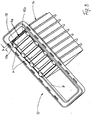
- Fig. 1 shows a heat exchanger network 1, consisting of corrugated fins 2 and flat tubes 3, which are flared end to rectangular flat tube ends 4. (The lower flat tube ends are not shown).
- the rectangular cross-section of the flat tube ends 4 has in each case two longitudinal sides 4a and two narrow sides 4b, the tube ends 4 abutting one another on their narrow sides 4a.
- Over the network (heat exchanger block) 1 is - in explosive representation - a rectangular closed frame 5 is arranged, which has an inner cutout 6, in which the pipe ends 4 of the block 1 are inserted.
- the frame 5 has an outer circumferential wall 7 and an inner, parallel to the outer extending wall 8, wherein between two walls 7, 8 a circumferential groove 9 is arranged, which serves to receive an endless (closed), not shown seal ,
- the outer wall 7 has a circumferential upper edge 7a, below which longitudinal slots 7b are arranged.
- the inner wall 8 has an upper edge 8a, from which bent tabs 10 depart, which are preferably made in one piece with the frame 5.
- the rectangular frame 5 has two longitudinal sides 11 and two narrow sides 12, in the region of each of which a bottom piece 13 is arranged (the second left bottom piece is omitted for the sake of simplicity).
- the bottom piece 13 directly adjoins the circumferential groove 9, in the region of the upper edge 8a of the inner wall 8; the bottom piece 13 is thus part of a conventional tube bottom which is not present here, which is omitted because of the widened, adjacent tube ends 4. Furthermore, the drawing shows - in an exploded view - a side part 14 with a head part 15 and a middle part 16, to which another not shown here headboard connects downwards.
- the head part 15 has an angled profile strip 15 a with an end face 15 b and is adapted to the inner contour of the frame 5 below the bottom piece 13.
- two collection boxes not shown, the one with the framework known per se. Art., Z. B. according to DE 28 52 408 B1 (so-called Wellenschlitzbördelung) or according to DE 28 52 415 B1 of the applicant (so-called Wellenbördelung) are connected.
- Wellenschlitzbördelung are the longitudinal slots 7b required for the Shaft flaring, no slots are necessary.
- Fig. 2 shows a heat exchanger 17 according to the invention partially and in a perspective view.
- the items shown in Fig. 1 are here assembled, ie the heat exchanger block 1 is inserted with its expanded pipe ends 4 in the cutout 6 of the frame 5, so that the narrow sides 4b of the pipe ends 4 abut against the inner wall 8 of the frame 5 and partially from the tabs 10 are overruled.
- At the outermost corrugated fin 2 is the side part 14 with its central part 16, and its head part 15, 15a - not visible here - is located within the frame 5 in its cutout 6 and below the bottom piece 13.
- the profile strip 15a of the head part 15 thus abuts against the underside of the bottom piece 13.
- the illustration shows the heat exchanger before the soldering process.
- the utmost Pipe end 4 abuts with its outer longitudinal edge 4a to an inner boundary line 13a of the bottom piece 13.
- the heat exchanger 17 with not shown here Tightening straps - or another suitable tensioning device - in the Strained that across the flat tubes 3 pressure in the direction of the Arrow P is exercised. Maintaining this pressure, the heat exchanger 17 - without the collection boxes, not shown - in one spent soldering furnace shown and soldered there.
- the soldering process melts on the flat tubes 3 and / or on the corrugated fins 2 located Lot für, so that the block 1 sets in the direction of arrow P, d. H. in shortened its block size.
- Fig. 3 shows the heat exchanger 17 after the soldering process, with a gap s between the edge 13a of the bottom piece 13 and the longitudinal side 4a of the outermost tube end 4.
- the profile strip 15a of the side part 14 which follows the setting movement of the pipe ends 4 and bridges the gap s, ie forms a gap bridge by the profile strip 15a frontally abuts the one hand on the longitudinal side 4a of the pipe end 4, on the other hand on the underside of the bottom piece 13 and the inner wall 8 and soldered at these contact points.
Landscapes
- Engineering & Computer Science (AREA)
- Physics & Mathematics (AREA)
- Thermal Sciences (AREA)
- Mechanical Engineering (AREA)
- General Engineering & Computer Science (AREA)
- Heat-Exchange Devices With Radiators And Conduit Assemblies (AREA)
Applications Claiming Priority (2)
| Application Number | Priority Date | Filing Date | Title |
|---|---|---|---|
| DE200410003047 DE102004003047A1 (de) | 2004-01-20 | 2004-01-20 | Wärmeübertrager, insbesondere Kühlmittel- oder Ladeluftkühler für Kraftfahrzeuge |
| DE102004003047 | 2004-01-20 |
Publications (1)
| Publication Number | Publication Date |
|---|---|
| EP1557628A2 true EP1557628A2 (fr) | 2005-07-27 |
Family
ID=34625736
Family Applications (1)
| Application Number | Title | Priority Date | Filing Date |
|---|---|---|---|
| EP20040028831 Withdrawn EP1557628A2 (fr) | 2004-01-20 | 2004-12-06 | Echangeur de chaleur, en particulier radiateur de refroidissement ou radiateur d'air de suralimentation pour véhicule |
Country Status (2)
| Country | Link |
|---|---|
| EP (1) | EP1557628A2 (fr) |
| DE (1) | DE102004003047A1 (fr) |
Cited By (2)
| Publication number | Priority date | Publication date | Assignee | Title |
|---|---|---|---|---|
| FR2992713A1 (fr) * | 2012-06-29 | 2014-01-03 | Valeo Systemes Thermiques | Faisceau d'echange de chaleur et echangeur de chaleur comprenant ledit faisceau |
| CN112387889A (zh) * | 2020-10-27 | 2021-02-23 | 思维自动化设备(天津)有限公司 | 一种汽车中冷器扁管翅片插入工装 |
Families Citing this family (4)
| Publication number | Priority date | Publication date | Assignee | Title |
|---|---|---|---|---|
| DE102005038510A1 (de) * | 2005-07-30 | 2007-02-01 | Dr.Ing.H.C. F. Porsche Ag | Rippen/Rohrblock für einen Wärmeübertrager |
| DE102005040611A1 (de) * | 2005-08-27 | 2007-03-01 | Behr Gmbh & Co. Kg | Wärmeübertrager in Aluminiumbauweise, insbesondere für Kraftfahrzeuge |
| DE102007011278A1 (de) | 2007-03-08 | 2008-09-11 | Volkswagen Ag | Kühler |
| DE202008006605U1 (de) | 2008-05-15 | 2008-08-07 | Behr Gmbh & Co. Kg | Wärmeübertrager und Rohrboden eines Wärmeübertragers |
Family Cites Families (8)
| Publication number | Priority date | Publication date | Assignee | Title |
|---|---|---|---|---|
| CH378353A (de) * | 1960-09-01 | 1964-06-15 | Urech Karl | Wärmeaustauscher mit plattenförmigen Austauschelementen |
| US4651816A (en) * | 1986-03-19 | 1987-03-24 | Modine Manufacturing Company | Heat exchanger module for a vehicle or the like |
| DE3722605A1 (de) * | 1987-07-09 | 1989-01-19 | Sueddeutsche Kuehler Behr | Ladeluftkuehler fuer verbrennungskraftmaschinen |
| DE3734523A1 (de) * | 1987-10-13 | 1989-04-27 | Sueddeutsche Kuehler Behr | Ladeluftkuehler |
| DE19547928C2 (de) * | 1995-06-30 | 1999-03-11 | Mtu Friedrichshafen Gmbh | Plattenwärmetauscher |
| DE19722097A1 (de) * | 1997-05-27 | 1998-12-03 | Behr Gmbh & Co | Wärmeübertrager sowie Wärmeübertrageranordnung für ein Kraftfahrzeug |
| DE19844848A1 (de) * | 1998-09-30 | 2000-04-06 | Modine Mfg Co | Wärmetauscher |
| DE10103584A1 (de) * | 2001-01-26 | 2002-08-01 | Modine Mfg Co | Wärmetauscher und Herstellungsverfahren |
-
2004
- 2004-01-20 DE DE200410003047 patent/DE102004003047A1/de not_active Withdrawn
- 2004-12-06 EP EP20040028831 patent/EP1557628A2/fr not_active Withdrawn
Cited By (2)
| Publication number | Priority date | Publication date | Assignee | Title |
|---|---|---|---|---|
| FR2992713A1 (fr) * | 2012-06-29 | 2014-01-03 | Valeo Systemes Thermiques | Faisceau d'echange de chaleur et echangeur de chaleur comprenant ledit faisceau |
| CN112387889A (zh) * | 2020-10-27 | 2021-02-23 | 思维自动化设备(天津)有限公司 | 一种汽车中冷器扁管翅片插入工装 |
Also Published As
| Publication number | Publication date |
|---|---|
| DE102004003047A1 (de) | 2005-08-11 |
Similar Documents
| Publication | Publication Date | Title |
|---|---|---|
| EP1703243B1 (fr) | Échangeur de chaleur avec tubes et ailettes et procédé de fabrication | |
| DE69109865T2 (de) | Verteiler- und Wärmetauscheranordnung Verteiler- und Wärmetauscheranordnung. | |
| EP0864838B1 (fr) | Echangeur de chaleur pour véhicule automobile | |
| DE69202964T2 (de) | Wärmetauscher. | |
| DE102014005149B4 (de) | Gelöteter Wärmetauscher | |
| DE69210452T2 (de) | Wärmetauscher mit Rohrbündel, insbesondere für Kraftfahrzeug | |
| EP0656517A1 (fr) | Echangeur de chaleur eau-air en aluminium pour véhicules automobiles | |
| EP0519334A2 (fr) | Echangeur de chaleur à tubes plats, procédé pour sa fabrication, applications et tubes plats pour échangeur de chaleur | |
| EP1687583A1 (fr) | Echangeur thermique, notamment refroidisseur d'air de suralimentation pour vehicules | |
| DE112005000230T5 (de) | Wärmetauscher-Sammelbehälter und Wärmetauscher beinhaltend das Gleiche | |
| EP1774245B1 (fr) | Echangeur thermique integralement metallique et procede de fabrication associe | |
| DE19722098A1 (de) | Wärmeübertrager für ein Kraftfahrzeug | |
| DE3834822A1 (de) | Waermetauscher | |
| EP1972879B1 (fr) | Échangeur de chaleur, en particulier radiateur pour liquide de refroidissement dans un véhicule automobile | |
| DE102008021544B4 (de) | Herstellungsverfahren für Wärmetauscher und Wärmetauscher | |
| EP1557628A2 (fr) | Echangeur de chaleur, en particulier radiateur de refroidissement ou radiateur d'air de suralimentation pour véhicule | |
| EP1731864A1 (fr) | Echangeur de chaleur métallique et procédé de fabrication de celui-ci | |
| DE69903241T2 (de) | Wärmetauscher, insbesondere verflüssiger für kraftfahrzeug und verfahren zu dessen herstellung | |
| DE4106296C2 (de) | Wärmetauscher, insbesondere Wasser/Luft-Kühler für Brennkraftmaschinen | |
| EP2167895A1 (fr) | Échangeur de chaleur | |
| EP1492991B1 (fr) | Echangeur de chaleur soude | |
| DE19605340C2 (de) | Wärmeübertrager und Verfahren zu seiner Herstellung | |
| DE19746371A1 (de) | Wärmetauscher mit einem Sammelkasten mit zwei aneinander angrenzenden Kammern | |
| DE102008035020A1 (de) | Wärmeübertrager | |
| DE102007006235A1 (de) | Wärmeübertrager in Ganzaluminiumbauweise, insbesondere für Kraftfahrzeuge |
Legal Events
| Date | Code | Title | Description |
|---|---|---|---|
| PUAI | Public reference made under article 153(3) epc to a published international application that has entered the european phase |
Free format text: ORIGINAL CODE: 0009012 |
|
| AK | Designated contracting states |
Kind code of ref document: A2 Designated state(s): AT BE BG CH CY CZ DE DK EE ES FI FR GB GR HU IE IS IT LI LT LU MC NL PL PT RO SE SI SK TR |
|
| AX | Request for extension of the european patent |
Extension state: AL BA HR LV MK YU |
|
| STAA | Information on the status of an ep patent application or granted ep patent |
Free format text: STATUS: THE APPLICATION IS DEEMED TO BE WITHDRAWN |
|
| 18D | Application deemed to be withdrawn |
Effective date: 20090701 |