EP1557258B1 - Radial expandierte rohrförmige Polytetrafluorethylentransplantate und Verfahren zu ihrer Herstellung - Google Patents
Radial expandierte rohrförmige Polytetrafluorethylentransplantate und Verfahren zu ihrer Herstellung Download PDFInfo
- Publication number
- EP1557258B1 EP1557258B1 EP05007944.1A EP05007944A EP1557258B1 EP 1557258 B1 EP1557258 B1 EP 1557258B1 EP 05007944 A EP05007944 A EP 05007944A EP 1557258 B1 EP1557258 B1 EP 1557258B1
- Authority
- EP
- European Patent Office
- Prior art keywords
- ptfe
- graft
- eptfe
- scanning electron
- radially
- Prior art date
- Legal status (The legal status is an assumption and is not a legal conclusion. Google has not performed a legal analysis and makes no representation as to the accuracy of the status listed.)
- Expired - Lifetime
Links
Images
















Classifications
-
- A—HUMAN NECESSITIES
- A61—MEDICAL OR VETERINARY SCIENCE; HYGIENE
- A61L—METHODS OR APPARATUS FOR STERILISING MATERIALS OR OBJECTS IN GENERAL; DISINFECTION, STERILISATION OR DEODORISATION OF AIR; CHEMICAL ASPECTS OF BANDAGES, DRESSINGS, ABSORBENT PADS OR SURGICAL ARTICLES; MATERIALS FOR BANDAGES, DRESSINGS, ABSORBENT PADS OR SURGICAL ARTICLES
- A61L27/00—Materials for grafts or prostheses or for coating grafts or prostheses
- A61L27/50—Materials characterised by their function or physical properties, e.g. injectable or lubricating compositions, shape-memory materials, surface modified materials
- A61L27/507—Materials characterised by their function or physical properties, e.g. injectable or lubricating compositions, shape-memory materials, surface modified materials for artificial blood vessels
-
- A—HUMAN NECESSITIES
- A61—MEDICAL OR VETERINARY SCIENCE; HYGIENE
- A61F—FILTERS IMPLANTABLE INTO BLOOD VESSELS; PROSTHESES; DEVICES PROVIDING PATENCY TO, OR PREVENTING COLLAPSING OF, TUBULAR STRUCTURES OF THE BODY, e.g. STENTS; ORTHOPAEDIC, NURSING OR CONTRACEPTIVE DEVICES; FOMENTATION; TREATMENT OR PROTECTION OF EYES OR EARS; BANDAGES, DRESSINGS OR ABSORBENT PADS; FIRST-AID KITS
- A61F2/00—Filters implantable into blood vessels; Prostheses, i.e. artificial substitutes or replacements for parts of the body; Appliances for connecting them with the body; Devices providing patency to, or preventing collapsing of, tubular structures of the body, e.g. stents
- A61F2/02—Prostheses implantable into the body
- A61F2/04—Hollow or tubular parts of organs, e.g. bladders, tracheae, bronchi or bile ducts
- A61F2/06—Blood vessels
-
- A—HUMAN NECESSITIES
- A61—MEDICAL OR VETERINARY SCIENCE; HYGIENE
- A61F—FILTERS IMPLANTABLE INTO BLOOD VESSELS; PROSTHESES; DEVICES PROVIDING PATENCY TO, OR PREVENTING COLLAPSING OF, TUBULAR STRUCTURES OF THE BODY, e.g. STENTS; ORTHOPAEDIC, NURSING OR CONTRACEPTIVE DEVICES; FOMENTATION; TREATMENT OR PROTECTION OF EYES OR EARS; BANDAGES, DRESSINGS OR ABSORBENT PADS; FIRST-AID KITS
- A61F2/00—Filters implantable into blood vessels; Prostheses, i.e. artificial substitutes or replacements for parts of the body; Appliances for connecting them with the body; Devices providing patency to, or preventing collapsing of, tubular structures of the body, e.g. stents
- A61F2/02—Prostheses implantable into the body
- A61F2/04—Hollow or tubular parts of organs, e.g. bladders, tracheae, bronchi or bile ducts
- A61F2/06—Blood vessels
- A61F2/07—Stent-grafts
-
- A—HUMAN NECESSITIES
- A61—MEDICAL OR VETERINARY SCIENCE; HYGIENE
- A61L—METHODS OR APPARATUS FOR STERILISING MATERIALS OR OBJECTS IN GENERAL; DISINFECTION, STERILISATION OR DEODORISATION OF AIR; CHEMICAL ASPECTS OF BANDAGES, DRESSINGS, ABSORBENT PADS OR SURGICAL ARTICLES; MATERIALS FOR BANDAGES, DRESSINGS, ABSORBENT PADS OR SURGICAL ARTICLES
- A61L27/00—Materials for grafts or prostheses or for coating grafts or prostheses
- A61L27/14—Macromolecular materials
- A61L27/16—Macromolecular materials obtained by reactions only involving carbon-to-carbon unsaturated bonds
-
- A—HUMAN NECESSITIES
- A61—MEDICAL OR VETERINARY SCIENCE; HYGIENE
- A61L—METHODS OR APPARATUS FOR STERILISING MATERIALS OR OBJECTS IN GENERAL; DISINFECTION, STERILISATION OR DEODORISATION OF AIR; CHEMICAL ASPECTS OF BANDAGES, DRESSINGS, ABSORBENT PADS OR SURGICAL ARTICLES; MATERIALS FOR BANDAGES, DRESSINGS, ABSORBENT PADS OR SURGICAL ARTICLES
- A61L31/00—Materials for other surgical articles, e.g. stents, stent-grafts, shunts, surgical drapes, guide wires, materials for adhesion prevention, occluding devices, surgical gloves, tissue fixation devices
- A61L31/04—Macromolecular materials
- A61L31/048—Macromolecular materials obtained by reactions only involving carbon-to-carbon unsaturated bonds
-
- B—PERFORMING OPERATIONS; TRANSPORTING
- B29—WORKING OF PLASTICS; WORKING OF SUBSTANCES IN A PLASTIC STATE IN GENERAL
- B29C—SHAPING OR JOINING OF PLASTICS; SHAPING OF MATERIAL IN A PLASTIC STATE, NOT OTHERWISE PROVIDED FOR; AFTER-TREATMENT OF THE SHAPED PRODUCTS, e.g. REPAIRING
- B29C48/00—Extrusion moulding, i.e. expressing the moulding material through a die or nozzle which imparts the desired form; Apparatus therefor
- B29C48/022—Extrusion moulding, i.e. expressing the moulding material through a die or nozzle which imparts the desired form; Apparatus therefor characterised by the choice of material
-
- B—PERFORMING OPERATIONS; TRANSPORTING
- B29—WORKING OF PLASTICS; WORKING OF SUBSTANCES IN A PLASTIC STATE IN GENERAL
- B29C—SHAPING OR JOINING OF PLASTICS; SHAPING OF MATERIAL IN A PLASTIC STATE, NOT OTHERWISE PROVIDED FOR; AFTER-TREATMENT OF THE SHAPED PRODUCTS, e.g. REPAIRING
- B29C48/00—Extrusion moulding, i.e. expressing the moulding material through a die or nozzle which imparts the desired form; Apparatus therefor
- B29C48/03—Extrusion moulding, i.e. expressing the moulding material through a die or nozzle which imparts the desired form; Apparatus therefor characterised by the shape of the extruded material at extrusion
- B29C48/09—Articles with cross-sections having partially or fully enclosed cavities, e.g. pipes or channels
-
- B—PERFORMING OPERATIONS; TRANSPORTING
- B29—WORKING OF PLASTICS; WORKING OF SUBSTANCES IN A PLASTIC STATE IN GENERAL
- B29C—SHAPING OR JOINING OF PLASTICS; SHAPING OF MATERIAL IN A PLASTIC STATE, NOT OTHERWISE PROVIDED FOR; AFTER-TREATMENT OF THE SHAPED PRODUCTS, e.g. REPAIRING
- B29C55/00—Shaping by stretching, e.g. drawing through a die; Apparatus therefor
- B29C55/005—Shaping by stretching, e.g. drawing through a die; Apparatus therefor characterised by the choice of materials
-
- B—PERFORMING OPERATIONS; TRANSPORTING
- B29—WORKING OF PLASTICS; WORKING OF SUBSTANCES IN A PLASTIC STATE IN GENERAL
- B29C—SHAPING OR JOINING OF PLASTICS; SHAPING OF MATERIAL IN A PLASTIC STATE, NOT OTHERWISE PROVIDED FOR; AFTER-TREATMENT OF THE SHAPED PRODUCTS, e.g. REPAIRING
- B29C55/00—Shaping by stretching, e.g. drawing through a die; Apparatus therefor
- B29C55/22—Shaping by stretching, e.g. drawing through a die; Apparatus therefor of tubes
- B29C55/24—Shaping by stretching, e.g. drawing through a die; Apparatus therefor of tubes radial
-
- B—PERFORMING OPERATIONS; TRANSPORTING
- B32—LAYERED PRODUCTS
- B32B—LAYERED PRODUCTS, i.e. PRODUCTS BUILT-UP OF STRATA OF FLAT OR NON-FLAT, e.g. CELLULAR OR HONEYCOMB, FORM
- B32B1/00—Layered products having a non-planar shape
- B32B1/08—Tubular products
-
- B—PERFORMING OPERATIONS; TRANSPORTING
- B32—LAYERED PRODUCTS
- B32B—LAYERED PRODUCTS, i.e. PRODUCTS BUILT-UP OF STRATA OF FLAT OR NON-FLAT, e.g. CELLULAR OR HONEYCOMB, FORM
- B32B27/00—Layered products comprising a layer of synthetic resin
- B32B27/06—Layered products comprising a layer of synthetic resin as the main or only constituent of a layer, which is next to another layer of the same or of a different material
- B32B27/08—Layered products comprising a layer of synthetic resin as the main or only constituent of a layer, which is next to another layer of the same or of a different material of synthetic resin
-
- B—PERFORMING OPERATIONS; TRANSPORTING
- B32—LAYERED PRODUCTS
- B32B—LAYERED PRODUCTS, i.e. PRODUCTS BUILT-UP OF STRATA OF FLAT OR NON-FLAT, e.g. CELLULAR OR HONEYCOMB, FORM
- B32B27/00—Layered products comprising a layer of synthetic resin
- B32B27/32—Layered products comprising a layer of synthetic resin comprising polyolefins
- B32B27/322—Layered products comprising a layer of synthetic resin comprising polyolefins comprising halogenated polyolefins, e.g. PTFE
-
- A—HUMAN NECESSITIES
- A61—MEDICAL OR VETERINARY SCIENCE; HYGIENE
- A61F—FILTERS IMPLANTABLE INTO BLOOD VESSELS; PROSTHESES; DEVICES PROVIDING PATENCY TO, OR PREVENTING COLLAPSING OF, TUBULAR STRUCTURES OF THE BODY, e.g. STENTS; ORTHOPAEDIC, NURSING OR CONTRACEPTIVE DEVICES; FOMENTATION; TREATMENT OR PROTECTION OF EYES OR EARS; BANDAGES, DRESSINGS OR ABSORBENT PADS; FIRST-AID KITS
- A61F2/00—Filters implantable into blood vessels; Prostheses, i.e. artificial substitutes or replacements for parts of the body; Appliances for connecting them with the body; Devices providing patency to, or preventing collapsing of, tubular structures of the body, e.g. stents
- A61F2/82—Devices providing patency to, or preventing collapsing of, tubular structures of the body, e.g. stents
- A61F2/86—Stents in a form characterised by the wire-like elements; Stents in the form characterised by a net-like or mesh-like structure
- A61F2/90—Stents in a form characterised by the wire-like elements; Stents in the form characterised by a net-like or mesh-like structure characterised by a net-like or mesh-like structure
-
- A—HUMAN NECESSITIES
- A61—MEDICAL OR VETERINARY SCIENCE; HYGIENE
- A61F—FILTERS IMPLANTABLE INTO BLOOD VESSELS; PROSTHESES; DEVICES PROVIDING PATENCY TO, OR PREVENTING COLLAPSING OF, TUBULAR STRUCTURES OF THE BODY, e.g. STENTS; ORTHOPAEDIC, NURSING OR CONTRACEPTIVE DEVICES; FOMENTATION; TREATMENT OR PROTECTION OF EYES OR EARS; BANDAGES, DRESSINGS OR ABSORBENT PADS; FIRST-AID KITS
- A61F2/00—Filters implantable into blood vessels; Prostheses, i.e. artificial substitutes or replacements for parts of the body; Appliances for connecting them with the body; Devices providing patency to, or preventing collapsing of, tubular structures of the body, e.g. stents
- A61F2/02—Prostheses implantable into the body
- A61F2/04—Hollow or tubular parts of organs, e.g. bladders, tracheae, bronchi or bile ducts
- A61F2/06—Blood vessels
- A61F2/07—Stent-grafts
- A61F2002/072—Encapsulated stents, e.g. wire or whole stent embedded in lining
-
- B—PERFORMING OPERATIONS; TRANSPORTING
- B29—WORKING OF PLASTICS; WORKING OF SUBSTANCES IN A PLASTIC STATE IN GENERAL
- B29K—INDEXING SCHEME ASSOCIATED WITH SUBCLASSES B29B, B29C OR B29D, RELATING TO MOULDING MATERIALS OR TO MATERIALS FOR MOULDS, REINFORCEMENTS, FILLERS OR PREFORMED PARTS, e.g. INSERTS
- B29K2027/00—Use of polyvinylhalogenides or derivatives thereof as moulding material
- B29K2027/12—Use of polyvinylhalogenides or derivatives thereof as moulding material containing fluorine
- B29K2027/18—PTFE, i.e. polytetrafluoroethylene, e.g. ePTFE, i.e. expanded polytetrafluoroethylene
-
- B—PERFORMING OPERATIONS; TRANSPORTING
- B32—LAYERED PRODUCTS
- B32B—LAYERED PRODUCTS, i.e. PRODUCTS BUILT-UP OF STRATA OF FLAT OR NON-FLAT, e.g. CELLULAR OR HONEYCOMB, FORM
- B32B2262/00—Composition or structural features of fibres which form a fibrous or filamentary layer or are present as additives
- B32B2262/02—Synthetic macromolecular fibres
- B32B2262/0253—Polyolefin fibres
-
- B—PERFORMING OPERATIONS; TRANSPORTING
- B32—LAYERED PRODUCTS
- B32B—LAYERED PRODUCTS, i.e. PRODUCTS BUILT-UP OF STRATA OF FLAT OR NON-FLAT, e.g. CELLULAR OR HONEYCOMB, FORM
- B32B2535/00—Medical equipment, e.g. bandage, prostheses or catheter
Definitions
- Microporous expanded polytetrafluoroethylene (“ePTFE”) tubes may made by any one of different, but well known, methods. Expanded polytetrafluoroethylene is typically made by admixing particulate dry polytetrafluoroethylene resin with a lubricant to form a viscous slurry. The admixture is poured into a mold, typically a cylindrical mold, and compressed under the influence of a positive pressure to form a cylindrical billet. The billet is then ram extruded through an extrusion die into either tubular or sheet structures termed in the art as extrudates.
- ePTFE expanded polytetrafluoroethylene
- the extrudates consist of extruded polytetrafluoroethylene-lubricant admixture, termed in the art as "wet PTFE.”
- Wet PTFE has a microstructure of coalesced, coherent PTFE resin particles in a highly crystalline state. After extrusion, the wet PTFE is exposed to a temperature below the flash point of the lubricant to volatilize a major fraction of the lubricant from the PTFE extrudate.
- the resulting PTFE extrudate without a major fraction of lubricant is known in the art as dried PTFE.
- the dried PTFE is then either uniaxially, biaxially or radially expanded using appropriate mechanical apparatus known in the art.
- Expansion is typically carried out at an elevated temperature, e.g., above room temperature but below 327 °C, the crystalline melt point of polytetrafluoroethylene.
- Uniaxial, biaxial or radial expansion of the dried PTFE causes the coalesced, coherent PTFE resin to form fibrils emanating from nodes, with the fibrils oriented parallel to the axis of expansion.
- the dried PTFE is referred to as expanded PTFE ("ePTFE”) or microporous PTFE.
- Sintered ePTFE articles exhibit significant resistance to further uniaxial, or radial expansion. This property has lead many in the art to devise techniques which entail endoluminal delivery and placement of an ePTFE graft having a desired fixed diameter, followed by endoluminal delivery and placement of an endoluminal prosthesis, such as a stent or other fixation device, to frictionally engage the endoluminal prosthesis within the lumen of the anatomical passageway.
- the Kreamer Patent, U.S. Patent No. 5,078,726, issued in 1992 exemplifies such use of an ePTFE prosthetic graft.
- Kreamer discloses a method of excluding an abdominal aortic aneurysm which entails providing a tubular PTFE graft which has a diameter corresponding to that of the inside diameter of a healthy section of the abdominal aorta, delivering the tubular PTFE graft and positioning the graft so that it spans the abdominal aorta.
- Prosthetic balloon expandable stents are then delivered and placed proximal and distal the abdominal aorta and within the lumen of the tubular PTFE graft.
- the prosthetic stents are then balloon expanded to frictionally engage the proximal and distal ends of the tubular PTFE graft against the inner luminal wall of healthy sections of the abdominal aorta.
- JP H07-67894A relates to an artificial blood vessel to be used in medical applications.
- US 4,187,390 is further prior art.
- the invention is defined by claim 1.
- the present invention provides a radially, plastically deformable tubular ePTFE material, having a microstructure of nodes interconnected by fibrils, with the nodes being substantially perpendicular to the longitudinal axis of the tubular ePTFE material and the fibrils being oriented parallel to the longitudinal axis of the tubular ePTFE material.
- Radial expansion of the inventive ePTFE material deforms the ePTFE microstructure by elongating the nodes while substantially retaining the internodal distances (IND) between adjacent nodes in the longitudinal axis of the ePTFE tube.
- IND internodal distances
- Internodal Distance refers to an average distance between two adjacent nodes measured along the longitudinal axis of each node between the facing surfaces of the adjacent nodes. IND is expressed in microns ( ⁇ ) as the unit of measure.
- Node refers to the solid region within an ePTFE material at which fibrils originate and converge.
- Node Length refers to a distance measured along a straight line between the furthermost opposing end points of a single node.
- Node Width refers to a distance measured along a straight line drawn perpendicular to the longitudinal axis of a node between opposing longitudinal surfaces of a node.
- Plastic Deformation refers to the radial deformation of the ePTFE microstructure under the influence of a radially expansive force which deforms and elongates the Node Length and results in elastic recoil of the ePTFE material less than about 25%.
- Rapid Expandable refers to a property of the ePTFE tubular member to undergo radially-oriented Plastic Deformation mediated by Nodal Elongation.
- Structural Integrity refers to a condition of the ePTFE microstructure both pre and post-radial deformation in which the fibrils are substantially free of fractures or breaks and the ePTFE material is free of gross failures.
- the inventive ePTFE material of the present invention is capable of being radially expanded under the influence of a radially outward force applied from the lumen of the ePTFE tubular material to substantially uniformly deform the ePTFE material.
- the inventive ePTFE material is radially expandable to a diameter 700% its unexpanded diameter under the influence of pressures less than 6 atm, preferably less than or equal to about 4.0 to 4.5 atm., most preferably between 2-3 atm., while retaining the structural integrity of the ePTFE microstructure. Conservation of the structural integrity of the ePTFE material is determined by conservation of the ePTFE microstructure structural integrity.
- the ePTFE microstructure structural integrity is considered conserved where the following factors are met: 1) IND remains substantially the same as the unexpanded graft; 2) water entry pressure as measured by Association for the Advancement of Medical Instrumentation (AAMI) test method 8.2.4 remains within ⁇ 60% of the water entry pressure of the unexpanded graft; 3) the wall thickness of the graft, as determined by AAMI test method 8.7.4, maintains its concentricity as determined by a substantially uniform wall thickness within ⁇ 30% about the circumference of the graft; 4) average post-radial expansion wall thickness remains within about ⁇ 70% of the average pre-radial expansion wall thickness as determined by AAMI test method 8.7.4; 5) longitudinal tensile strength as measured by AAMI test method 8.3.2 remains within ⁇ 100% of the value of the unexpanded graft, when normalized for wall thickness; 6) radial tensile
- a longitudinally expanded polytetrafluoroethylene tubular member having a continuous substantially concentric wall surface which has no seam and which is radially deformable between about 50% to about 700% its original diameter with application of a radially directed outward pressure of less than about 6 atm, preferably less than or equal to about 4 to 4.5 atm without loss of structural integrity.
- Structural integrity is considered retained where the microstructure of the ePTFE after radial expansion, is substantially free of broken or fractured fibrils and where the following factors are met: 1) IND remains substantially the same as the unexpanded graft; 2) water entry pressure as measured by Association for the Advancement of Medical Instrumentation (AAMI) test method 8.2.4 remains within ⁇ 60% of the water entry pressure of the unexpanded graft; 3) the wall thickness of the graft, as determined by AAMI test method 8.7.4, maintains its concentricity as determined by a substantially uniform wall thickness within ⁇ 30% about the circumference of the graft; 4) average post-radial expansion wall thickness remains within about ⁇ 70% of the average pre-radial expansion wall thickness as determined by AAMI test method 8.7.4; 5) longitudinal tensile strength as measured by AAMI test method 8.3.2 remains within ⁇ 100% of the value of the unexpanded graft, when normalized for wall thickness; 6) radial tensile strength as
- longitudinally expanded polytetrafluoroethylene (ePTFE) tubular structures may be made by ram extruding a compressed billet of polytetrafluoroethylene resin and a lubricant extrusion aid through an annular orifice formed by an extrusion die and a mandrel to form a tubular extrudate.
- the tubular extrudate is free of seams, overlaps, crimps, folds, or the like. While the tubular extrudate still contains the lubricant it is referred to as being "wet.”
- the wet extrudate lacks dimensional stability, is easily damaged, and is difficult to manipulate or otherwise process without removing the lubricant.
- lubricant is removed and the extrudate "dried" by heating the wet extrudate to a temperature below the flash point of the lubricant and below the crystalline melt temperature of the PTFE resin which volatilizes the lubricant from the PTFE resin.
- Dimensional stability and the degree to which the extrudate may be manipulated or processed is related to the concentration of lubricant in the extrudate.
- the extrudate may be partially or fully dried, depending upon the residual lubricant concentration desired, by varying the dwell or residence time of the wet extrudate in the drying oven.
- the dried extrudate is longitudinally expanded at a temperature below the crystalline melt temperature of the PTFE resin. Longitudinal expansion is performed at a rate of between about 5%/sec. to about 800%/sec. with the final expansion ratio being between 2:1 to 6:1.
- the ends of the longitudinally expanded PTFE are constrained against shortening and the ePTFE is exposed to a temperature above the crystalline melt temperature of the PTFE resin for a period of time to sinter the PTFE and amorphously lock the node-fibril microstructure and stabilize the porosity of the ePTFE tubular structure.
- Figure 1 depicts a radially expandable ePTFE tubular member 10 in accordance with the present invention.
- the inventive ePTFE tubular member 10 has an inner diameter d and is shown with a portion of its outer surface cut away and microscopically enlarged to illustrate the ePTFE microstructure 12.
- the ePTFE microstructure consists of a plurality of nodes 14 interconnected by a plurality of fibrils 16.
- the plurality of fibrils 16 emanate from and converge to the plurality of nodes 14 spanning the internodal distance a .
- the plurality of nodes 14 are each substantially solid, have a node length b which is generally perpendicular to the longitudinal axis of the ePTFE tubular member 10 and parallel with the transverse axis of the ePTFE tubular member 10.
- the radially deformable ePTFE tubular member 10 of the present invention is particularly well suited for use as a covering or liner for an endoluminal stent.
- Endoluminal stents are generally of three types. Balloon expandable endoluminal stents require the application of a positive pressure to the stent to radially deform the stent beyond the elastic limit of the material used to make the stent. Balloon expandable stents are represented in the art by PALMAZ patents.
- Self-expanding endoluminal stents are made with a configuration which takes advantage of the elastic properties of the stent material and are radially constrained by a restraining sheath during endoluminal delivery and undergo elastic expansion to their unconstrained diameter when the restraining sheath is removed.
- Self expanding stents are represented in the art by the GIANTURCO or WALLSTENT.
- shape memory stents are made of shape memory materials, such as nickel-titanium alloys known as NITINOL, which expand upon exposure to a temperature differential, e.g., expands at body temperature. Any of the foregoing endoluminal stent types may be covered, lined or encapsulated by the inventive radially deformable ePTFE tubular member 10 and radially expanded either in vivo or in vitro.
- Figures 3A and 3B illustrate the inventive radially expandable ePTFE material 10 encapsulating an endoluminal stent 20, as more fully described in commonly assigned, co-pending application published as PCT International Application WO96/28115, published 19 September, 1996 , claiming priority from co-pending U.S. Patent Applications Serial Nos. 08/401,871 filed March 10, 1995 and 08/508,033 filed July 27, 1995 .
- Figure 3A illustrates an encapsulated stent graft 20 in its pre-radially expanded diameter
- Figure 3B illustrates an encapsulated stent graft 30 in its post-radially expanded diameter.
- the encapsulated stent graft assembly consisting generally of radially expandable ePTFE material 10 and endoluminal stent 20, are concentrically positioned about a catheter balloon 34 mounted on the distal end of a balloon catheter 32.
- the catheter balloon 34 defines an inflation chamber 36 therein which receives a pressurized inflation fluid (not shown) from a external source (not shown).
- a pressurized inflation fluid not shown
- an outwardly directed radial force is exerted substantially uniformly against the luminal surface of the stent graft assembly, thereby urging the stent-graft assembly from its smaller delivery diameter to a larger final diameter depicted in Figure 3B .
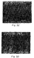
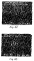
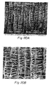
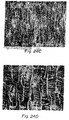
- Figures 5A-5D are scanning electron micrographs taken at 200X and 500X magnification of the inner and outer surfaces of a standard ePTFE vascular graft (Lot 34391, IMPRA, Inc., Tempe, Arizona). It will be noted that the node-fibril microstructure of the ePTFE is characterized by irregular node patterns and fibrils which are substantially cylindrical as reflected by the substantially parallel surfaces along the longitudinal axis of each fibril.
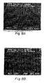
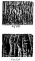
- Figures 6A-6D are scanning electron micrographs taken at 200 and 500X magnification of the inner and outer surfaces of the standard ePTFE vascular graft of Figures 5A-5D which has been radially expanded 3X to an inner diameter of 9 mm.
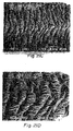
- Figures 7A-7D are scanning electron micrographs of the inner and outer surfaces of the standard ePTFE vascular graft of Figures 5A-5D which has been radially expanded 4X to an inner diameter of 12 mm.
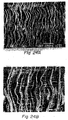
- Figures 8A-8D are scanning electron micrographs of the inner and outer surfaces of the standard ePTFE vascular graft of Figures 5A-5D which has been radially expanded 4X to an inner diameter of 15 mm.
- the nodes have a largely irregular elongate appearance and are asynchronously arrayed in the microstructure. While average outer surface internodal distance of the base graft is 33 ⁇ , at 3X is 33 ⁇ , at 4X is 32 ⁇ and at 5X is 33 ⁇ , the micrographs illustrate that the INDs have a non-uniform distribution throughout the material matrix. Morphologically, it will be seen that radial expansion of the conventional IMPRA ePTFE vascular graft results in elongation and thinning of the nodes, which remain irregular in shape, but the INDs continue to have a non-uniform distribution in the material matrix.
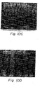
- Figures 9A-D are micrographs of inner and outer surfaces of a non-radially expanded 6 mm ID ePTFE graft (Lot No. 34396, IMPRA, Inc., Tempe, Arizona).
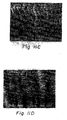
- Figures 10A-10B are scanning electron micrographs taken at 200 and 500X magnification of the inner and outer surfaces of the standard ePTFE vascular graft of Figures 9A-9D which has been radially expanded 3X to an inner diameter of 18 mm.
- Figures 11A-11D are scanning electron micrographs of the inner and outer surfaces of the standard ePTFE vascular graft of Figures 9A-9D which has been radially expanded 4X to an inner diameter of 24 mm.
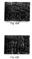
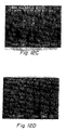
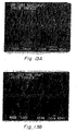
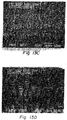
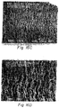
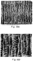
- the inventive rePTFE material represented herein by ERF 1683, ERF 1687 and ERF 1689, shown in their non-radially expanded base state, and at 3X, 4X and 5X radial expansion, in Figures 13A-24C , is characterized by a lower node density and lower fibril density in the unexpanded and expanded graft material. Scanning electron microscopy was performed on a JEOL-SM 840 Scanning Electron Microscope and the accompanying micrographs were obtained during scanning electron microscopy.
- the lower node density is the result of elongation of the nodes as the graft radially expands, while the lower fibril density is the result of increasing interfibril distances due to the nodal elongation.
- Interfibril distance is the perpendicular distance between any two parallel and adjacent fibrils.
- the nodes in the inventive rePTFE material are characterized by a more uniform regular elongate shape which, during radial expansion, undergo a more regular nodal elongation than that exhibited by the standard PTFE graft material, and fibrils which have a torroidal or "necked" profile. Additionally, as reflected in the accompanying figures, the rePTFE microstructure is characterized by increased tortuosity of the pores than that exhibited by the standard PTFE graft material.
- the base unexpanded graft has average INDs of approximately 18.2 ⁇ .
- the plurality of fibrils have a generally torroidal shape along their longitudinal axis, with the intermediate area of each of the plurality of fibrils having a narrower width than the area at either end of the plurality of fibrils 16 adjacent the nodes which the fibrils connect.
- the plurality of nodes exhibit a substantially parallel array with the nodes being substantially coaxially aligned in end-to-end fashion along the transverse axis of the graft material.
- the electron micrographs reflect that the each interfibrilar space is bounded in the z-axis by another fibril in close proximity to the interfibrilar space, which imparts the increased tortuosity of the rePTFE microstructure.
- the interfibril distance has increased relative to both the base graft, or the rePTFE graft at 3X or 4X radial expansion, while the IND remains substantially the same as that of the base rePTFE graft or that at 3X or 4X radial expansion.
- the nodes have again elongated along the axis of radial expansion to form long, columnar nodes which have a generally regular distribution throughout the microstructure wherein a substantial majority of the nodes are separated by substantially uniform INDs.
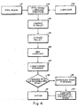
- Radially deformable, longitudinally expanded PTFE tubular graft members meeting the criteria of the present invention are made by the method 50 for making radially expandable PTFE tubes illustrated generally in Figure 4 .
- the general method steps consist of providing a polytetrafluoroethylene resin 51 preferably having an average molecular weight about 120 Million and an average particle size between 350 and 750 ⁇ , and an extrusion lubricant 52, such as ISOPAR H (Exxon Chemical), and admixing the PTFE resin and lubricant at step 53. It is preferable that the lubricant be present in the admixture at a ratio of between about 13.5% to about 18% by weight.
- an annular ram plate is engaged over the central co-axial vertical shaft and within the billet preform.
- a ram press is then engaged onto the annular ram plate and the PTFE-lubricant admixture is compressed under pressure until a compacted extrusion billet is formed at step 54.
- the extrusion billet produced at step 54 is then removed from the billet preform and the preform shaft and engaged upon an extrusion shaft and extrusion mandrel and introduced into the extrusion barrel of a ram extruder.
- tubular PTFE As the tubular PTFE is extruded, it issues from the die exit orifice as a continuous tubular PTFE extrudate and is cut using a sharp razor blade into any length desired, e.g., 30 cm lengths.
- the PTFE tubular extrudate lengths are then introduced into an oven at a temperature below the flash point of the lubricant, for example at 40° C for ISOPAR H (Exxon Chemical), for a period of time sufficient to drive off and dry, at step 56, substantially all of the lubricant present in the PTFE tubular extrudate, for example, for about 60 minutes.
- expansion plugs are secured into the tube lumen at each opposing end of the PTFE tubular extrudate length, and the plugged PTFE tubular extrudates are mounted onto an expansion rack.
- the expansion rack is designed to be mounted into an expansion oven and has a gear, screw, or rail driven moveable stage to which one end of the PTFE tubular extrudate is attached and a stationary stage to which another end of the PTFE tubular extrudate is attached.
- the PTFE tubular extrudate, mounted on the expansion rack, is introduced into an expansion oven heated to a temperature below the second crystalline melt point of PTFE, preferably between 125 and 340 °C, most preferably between 150 and 200 °C, and allowed to dwell in the expansion oven for a period of time between 5 and 10 minutes, preferably about 7-8 minutes, before longitudinally expanding the PTFE tubular extrudate.
- the unsintered PTFE extrudates may either be concentrically laminated with other larger or smaller diameter unsintered PTFE extrudates, or may be concentrically positioned about luminal and abluminal surfaces of an endoluminal stent at step 58.
- An endoluminal stent which may be a balloon expandable, self-expandable or a shape memory stent, may be introduced at step 59 by concentrically positioning an endoluminal stent around a first unsintered PTFE extrudate, then a second unsintered PTFE extrudate of a slightly larger inner diameter may be introduced concentrically around the first unsintered PTFE extrudate and the endoluminal stent, as more fully described in co-pending PCT International Application WO96/28115, published 19 September, 1996 , claiming priority from co-pending U.S. Patent Applications Serial Nos. 08/401,871 filed March 10, 1995 and 08/508,033 filed July 27, 1995 exemplifying a process for making an encapsulated stent graft.
- the PTFE tubular extrudates concentrically positioned relative to one another are then laminated by application of a helically applied tension wrap of non-porous PTFE tape which applies a circumferential pressure to the concentrically positioned laminated tubular PTFE extrudates and/or to the concentrically positioned laminated tubular PTFE extrudates and stent assembly at step 60.
- the wrapped assembly is then introduced into a sintering oven set to heat the wrapped assembly to a temperature above the second transition crystalline melt point of PTFE, i.e., above 342 °C, preferably 375 °C +10 -5, for a period of time sufficient to fully sinter the PTFE laminated assembly.
- Table 1 summarizes the preferred processing parameters used for making the inventive rePTFE tubular grafts which exhibit up to 700% radial expandability at applied pressures of less than about 6 atm, preferably less than or equal to about 4 atm., most preferably between 2-3 atm.
- ERF 1683 ERF 1687 ERF 1689 ERF encap Resin Type CD 123 CD 123 CD 123 CD 123 Resin Amt (g) 500 500 500 500 Lube Amt. (g) 87 87 100 110 Reduction Ratio 239 239 239 239 Expansion Ratio 5.3:1 5.3:1 5.3:1 6:1 Expansion Rate (%/sec) 200 10 200 200 Expansion Temp.
- a 3 mm inner diameter (ID) radially expandable ePTFE tube was fabricated by admixing 500g of CD-123 PTFE resin (ICI Americas, Inc.) with 87g of ISOPAR H (Exxon Chemicals), yielding a 17.4% lubricant level ("Lube Level") in the admixture.
- the admixture was mixed by rolling in a glass container, then incubated at 40°C for 6 to 8 hours. After incubation, the admixture was poured into a cylindrical pre-form having an inner diameter of 3.81 cm. And compressed in a vertical ram press at about 1,100 psi to form a cylindrical extrusion billet. The extrusion billet was carefully removed from the cylindrical pre-form, wrapped in aluminum foil and incubated prior to use.
- the extrusion billet was mounted onto a cylindrical stainless steel base shaft having a diameter of 0.357 cm which passed through the central longitudinal axis of the extrusion billet and projected beyond both ends of the extrusion billet.
- a tapered extrusion mandrel has a proximal end which is coupled to the base shaft and has proximal end diameter of 0.357cm and tapers to a mandrel tip at the distal end of the mandrel which has an outer diameter of 0.335 cm.
- the extrusion billet is then extruded in the ram extruder at an extrusion speed of 3000 mm/min to yield a wet tubular extrudate.
- the wet tubular extrudate is cut using a razor blade into 30 cm sections as it issues from the extrusion die.
- the 3 mm inner diameter radially expandable tubes produced in the Example 1 tube are hereinafter referred to as lot ERF 1683.
- Example 2 The same processing parameters were followed in as in Example 1, except that the expansion rate was changed to 10%/sec. 3 mm inner diameter radially expandable tubes produced in Example 2 are hereinafter referred to as lot ERF 1687.
- Example 3 The same processing parameters were followed as in Example 1, except that the lubricant amount was changed to 100g yielding a lube level of 20%.
- the 3 mm inner diameter radially expandable tubes produced in Example 3 are hereinafter referred to as lot ERF 1689.
- Example 4 The same process parameters were followed as in Example 1, except that the lubricant amount was changed to 110g, yielding a lube level of 22%, the expansion ratio was changed to 6:1, the PTFE extrudate was allowed to dwell in the expansion oven for 7 minutes prior to expansion and the expansion was conducted at 200 °C.
- the resulting 3 mm inner diameter radially expandable tubes produced in Example 4 are hereinafter referred to as lot ERF encap .
- the pre-dilated stents were then crimped down onto the mandrel and the outer surface of the 3 mm ePTFE graft.
- a 4 mm ID graft was loaded over the crimped stents.
- the 4 mm ePTFE graft was wire wrapped onto the assembly at its ends and between the crimped stents.
- the wrapped assembly was then warmed in a radiant heat oven at 340° C for 30 seconds and then removed.
- the entire assembly was then wrapped with TEFLON tape using a helical winder set to apply the winding at 1.7 psi.
- the wrapped assembly was then placed in a radiant heat sintering oven preheated to 400° C and heated at sintering temperatures of 367° C for a total of 8 minutes.
- the TEFLON taped assembly was then removed from the oven and the TEFLON tape and wire wraps were removed.
- the ePTFE grafts were then cut about one inch outside of each of the ends of the stents.
- the resulting encapsulated stents were gently removed from the mandrel one at a time and then cut to provide a 3 mm ePTFE overhang at both ends of the individual stents. Sintering in a radiant heat oven for longer periods of time than in a convection oven was found to increase the bond strength of the laminated PTFE layers in the encapsulated stent.
- RTS Radial Tensile Strength
- IND measurement is an evaluation of the node-fibril microstructure of the ePTFE graft.
- a 1 cm graft segment is cut longitudinally and the sample is flattened into a sheet.
- the surface to be studied is placed face up on a glass slide prepared with double sided tape.
- the surface is colored using a contrast dye such as aniline dye.
- Using an optical microscope with a calipered stage and reticle the average distance between 2 adjacent nodes is recorded. Three measurements are taken per sample for each side. These readings are then averaged for each of the inner surface (IND i ) and the outer surface (IND o ) of the ePTFE graft and are expressed in ⁇ or 1 x 10 -6 meters.
- Water Entry Pressure is an indirect measurement of the porosity of the graft which uses pressurized water to evaluate the graft's ability to retain fluid under pressure. Both ends of a 9cm graft sample are securely clamped with hemostats. A 22 gauge hypodermic needle is then introduced at a 45° angle through the graft wall land into the lumen. The graft is then slowly filled with distilled water until the internal water pressure reaches 0.8 to 1.8 psi. The pressure is then increased slowly until the first drop of water appears on the outside surface of the graft. The pressure, in psi, at which the water first appears is the WEP value.
- LFS Longitudinal Foreshortening
- Longitudinal foreshortening is a measurement of the amount by which the graft foreshortens upon radial expansion.
- a line is drawn along the length of every sample to be tested. The length of the line is measured both before and after radial expansion and the change in length is converted into a percentage by dividing the difference between initial and final lengths and dividing by the initial length.
- Each graft sample length (70-80 cm) was cut into 2 halves. A first was used for base graft testing and the second half was used for radial expansion. The second half for radial expansion was again cut into three 12 cm sections and each section was numbered with the graft number and an identifier indicating which test it was to be used for, e.g., 3X, 4X or 5X expansion. Each segment was then radially expanded to the maximum balloon diameter in the water bath then held for 1 minute. For the larger expansion ratios, i.e ., 5X, it was necessary to pre-expand the graft in order to permit the graft lumen to accept the larger profile balloon. After radial expansion, the balloon was deflated, and the graft removed and set aside for testing.
- Tables 3-7 set forth the averaged raw data obtained from testing a 6 mm ID standard PTFE vascular graft (Lot 34396, IMPRA, Inc., Tempe, Arizona), a 3 mm ID standard PTFE vascular graft (Lot 34391, IMPRA, Inc. Tempe Arizona), and the inventive rePTFE grafts, ERF 1683, ERF 1687, and ERF 1689.
- Figures 13A-24C are the scanning electron micrographs taken of the inner surface and the outer surface of each of the grafts for which the test data in Tables 4-7 is reflected.
- inventive rePTFE tubular graft suitable for endoluminal radial expansion at applied pressures of less than 6 atm has been described with reference to its preferred embodiments and with reference to an inventive method for making the rePTFE tubular endoluminal grafts.
- inventive rePTFE tubular grafts each consist of a longitudinally expanded polytetrafluoroethylene tubular member having a continuous substantially concentric wall surface which has no seam and which is radially deformable between about 50% to about 700% its original diameter with application of a radially directed outward pressure of less than about 6 atm without loss of structural integrity.
- Structural integrity is considered retained where the microstructure of the ePTFE after radial expansion is substantially free of broken or fractured fibrils and where the following factors are met: 1) IND remains substantially the same as the unexpanded graft; 2) water entry pressure as measured by Association for the Advancement of Medical Instrumentation (AAMI) test method 8.2.4 remains within ⁇ 60% of the water entry pressure of the unexpanded graft; 3) the wall thickness of the graft, as determined by AAMI test method 8.7.4, maintains its concentricity as determined by a substantially uniform wall thickness within ⁇ 30% about the circumference of the graft; 4) average post-radial expansion wall thickness remains within about ⁇ 70% of the average pre-radial expansion wall thickness as determined by AAMI test method 8.7.4; 5) longitudinal tensile strength as AAMI test method 8.3.2 remains within ⁇ 100% of the value of the unexpanded graft, when normalized for wall thickness; 6) radial tensile strength as measured by
- the invention previously described may be useful in providing a continuous tubular structure comprising an expanded polytetrafluoroethylene material having a microstructure characterized by a plurality of nodes interconnected by fibrils, the fibrils having an orientation substantially parallel to the longitudinal axis of the polytetrafluoroethylene tubular material and the nodes having a longitudinal axis substantially perpendicular to the longitudinal axis of the polytetrafluoroethylene material, the polytetrafluoroethylene tubular material being capable of undergoing radial deformation under the influence of a positive pressure applied through the lumen of the polytetrafluoroethylene tubular material and radially outward therefrom which causes a plurality of the nodes in the microstructure to undergo elongation along the longitudinal axis of the nodes, while substantially retaining an average internodal distance throughout the microstructure of the section of polytetrafluoroethylene tubular material which is radially deformed.
- the expanded polytetrafluoroethylene tubular material may be radially deformable between about 50% to 700% its original diameter without loss of structural integrity.
- the expanded polytetrafluoroethylene may be radially deformable to at least 50% its original diameter at applied positive pressures less than about 6 atm.
- the continuous tubular structure may further include a radially expandable stent member concentrically positioned within the lumen of the tubular structure.
- the radially expandable stent member may be selected from the group of stents consisting of balloon expandable, self expanding and memory shape stent members.
- the continuous tubular structure may further include a radially expandable stent member concentrically positioned about at least one of an outer, abluminal surface and a luminal surface of the continuous tubular structure.
- the radially expandable stent member may be selected from the group of stents consisting of balloon expandable, self expanding, and shape memory stent members.
- the invention previously described may also be useful in providing a tubular expanded polytetrafluoroethylene member comprising a material microstructure characterized by a plurality of nodes interconnected by fibrils, the fibrils having an orientation substantially parallel to the longitudinal axis of the polytetrafluoroethylene tubular material and the nodes having a longitudinal axis substantially perpendicular to the longitudinal axis of the polytetrafluoroethylene matieral, the polytetrafluoroethylene tubular material being capable of undergoing radial deformation under the influence of a positive pressure of less than or equal to about 6 atm applied through the lumen of the polytetrafluoroethylene tubular material and directed radially outward therefrom which acts to cause at least some of the nodes to elongate along their longitudinal axis while substantially retaining an average internodal distance throughout the microstructure of the section of polytetrafluoroethylene tubular material which is radially deformed substantially the same as that of the non-radially deformed expanded polytetra
Landscapes
- Health & Medical Sciences (AREA)
- Engineering & Computer Science (AREA)
- Life Sciences & Earth Sciences (AREA)
- Mechanical Engineering (AREA)
- Veterinary Medicine (AREA)
- Public Health (AREA)
- General Health & Medical Sciences (AREA)
- Animal Behavior & Ethology (AREA)
- Transplantation (AREA)
- Chemical & Material Sciences (AREA)
- Vascular Medicine (AREA)
- Oral & Maxillofacial Surgery (AREA)
- Epidemiology (AREA)
- Heart & Thoracic Surgery (AREA)
- Medicinal Chemistry (AREA)
- Gastroenterology & Hepatology (AREA)
- Pulmonology (AREA)
- Chemical Kinetics & Catalysis (AREA)
- Dermatology (AREA)
- Cardiology (AREA)
- Biomedical Technology (AREA)
- Surgery (AREA)
- Prostheses (AREA)
- Materials For Medical Uses (AREA)
- Manufacture Of Porous Articles, And Recovery And Treatment Of Waste Products (AREA)
- Shaping By String And By Release Of Stress In Plastics And The Like (AREA)
- Laminated Bodies (AREA)
- Graft Or Block Polymers (AREA)
- Treatments Of Macromolecular Shaped Articles (AREA)
Claims (19)
- Verfahren zur Herstellung eines länglichen laminierten expandierbaren Polytetrafluorethylen (PTFE) Elements, das auf zumindest 7 Mal seines unexpandierten Durchmessers durch einen Druck von weniger als 6 Atmosphären radial expandierbar ist, wobei das Verfahren die folgenden Schritte umfasst:Auswählen eines PTFE-Materials mit einem durchschnittlichen Molekulargewicht von ungefähr 120 Millionen und einer durchschnittlichen Partikelgröße in einem Bereich von ungefähr 350 bis ungefähr 750 Mikrometern (µm);Bereitstellen einer Mischung aus dem PTFE und einem Gleitmittel;Komprimieren der Mischung, um einen komprimierten Extrusionsrohling auszubilden;Extrudieren des Rohlings als extrudierte Stränge, um PTFE-Rohre auszubilden;Ausbilden der extrudierten Stränge in Rohrlängen;Trocknen der extrudierten Stränge;Expandieren jeder Rohrlänge bei einer Dehnungsgeschwindigkeit in einem Bereich von ungefähr 10%/Sek. bis 200%/Sek.;in Kontakt Bringen jeder Rohrlänge mit zumindest einem anderen ungesinterten länglichen PTFE-Extrusionserzeugnis, das einen von der Rohrlänge unterschiedlichen Durchmesser aufweist, um verschachtelte längliche Elemente auszubilden; undSintern der verschachtelten länglichen Elemente.
- Verfahren nach Anspruch 1, wobei das Auswählen ein Auswählen eines PTFE-Harzes umfasst.
- Verfahren nach Anspruch 2, wobei das Bereitstellen der Mischung ein Kühlen der Mischung über Nacht umfasst.
- Verfahren nach Anspruch 3, wobei das Bereitstellen ein Beimischen des Gleitmittels zu dem PTFE-Harz von einem Verhältnis von ungefähr 13% bis ungefähr 18% nach Gewicht umfasst.
- Verfahren nach Anspruch 3, wobei das Extrudieren ein Drängen der Mischung durch eine Öffnung umfasst.
- Verfahren nach Anspruch 5, wobei das Drängen ein Verringern eines Querschnittbereichs der Mischung um ein Verringerungsverhältnis von 239 durch die Öffnung umfasst.
- Verfahren nach Anspruch 5, wobei das Extrudieren ein Entfernen des Gleitmittels von dem extrudierten Strang umfasst.
- Verfahren nach Anspruch 7, wobei das Expandieren ein Erwärmen des extrudierten Strangs auf im Allgemeinen eine erste Temperatur unterhalb eines zweiten kristallinen Schmelzpunkts von PTFE über einen ersten Zeitraum umfasst.
- Verfahren nach Anspruch 8, wobei die Temperatur eine Temperatur von ungefähr 125 Grad Celsius bis ungefähr 340 Grad Celsius umfasst.
- Verfahren nach Anspruch 9, wobei die Temperatur eine Temperatur von ungefähr 150 Grad Celsius bis ungefähr 200 Grad Celsius umfasst.
- Verfahren nach Anspruch 9, wobei der erste Zeitraum von ungefähr 5 Minuten bis ungefähr 10 Minuten umfasst.
- Verfahren nach Anspruch 10, wobei der erste Zeitraum von ungefähr 7 Minuten bis ungefähr 8 Minuten umfasst.
- Verfahren nach Anspruch 1, wobei das in Kontakt Bringen ein Laminieren jeder Rohrlänge mit zumindest einem ungesinterten länglichen PTFE-Element umfasst.
- Verfahren nach Anspruch 12, wobei das Sintern ein Umwickeln der verschachtelten länglichen Elemente mit nicht-porösem PTFE-Band umfasst, um eine umwickelte PTFE-Anordnung bereitzustellen.
- Verfahren nach Anspruch 14, wobei das Umwickeln ein Erwärmen der umwickelten PTFE-Anordnung auf eine zweite Temperatur oberhalb eines zweiten kristallinen Übergangsschmelzpunkts von PTFE über einen zweiten Zeitraum umfasst.
- Verfahren nach Anspruch 15, wobei das Erwärmen ein Erwärmen der umwickelten PTFE-Anordnung in einem Sinterofen mit einer Strahlungswärmequelle umfasst.
- Verfahren nach Anspruch 16, wobei die zweite Temperatur ungefähr 375 Grad Celsius umfasst.
- Verfahren nach Anspruch 16, wobei der zweite Zeitraum eine Dauer von ungefähr 8 bis ungefähr 12 Minuten umfasst.
- Verfahren nach Anspruch 18, wobei das Erwärmen ein Erwärmen in einem Konvektionsofen auf eine Temperatur oberhalb von 342 Grad Celsius über einen Zeitraum von ungefähr 45 bis ungefähr 90 Sekunden umfasst.
Priority Applications (1)
| Application Number | Priority Date | Filing Date | Title |
|---|---|---|---|
| EP10183365.5A EP2295007A3 (de) | 1997-02-05 | 1998-02-02 | Radial expandierte rohrförmige Polytetrafluorethylentransplantate und Verfahren zu ihrer Herstellung |
Applications Claiming Priority (3)
| Application Number | Priority Date | Filing Date | Title |
|---|---|---|---|
| US794871 | 1997-02-05 | ||
| US08/794,871 US6039755A (en) | 1997-02-05 | 1997-02-05 | Radially expandable tubular polytetrafluoroethylene grafts and method of making same |
| EP19980906213 EP1003440B1 (de) | 1997-02-05 | 1998-02-02 | Radial expandierte rohrförmige polytetrafluorethylentransplantate |
Related Parent Applications (1)
| Application Number | Title | Priority Date | Filing Date |
|---|---|---|---|
| EP19980906213 Division EP1003440B1 (de) | 1997-02-05 | 1998-02-02 | Radial expandierte rohrförmige polytetrafluorethylentransplantate |
Related Child Applications (2)
| Application Number | Title | Priority Date | Filing Date |
|---|---|---|---|
| EP10183365.5A Division-Into EP2295007A3 (de) | 1997-02-05 | 1998-02-02 | Radial expandierte rohrförmige Polytetrafluorethylentransplantate und Verfahren zu ihrer Herstellung |
| EP10183365.5A Division EP2295007A3 (de) | 1997-02-05 | 1998-02-02 | Radial expandierte rohrförmige Polytetrafluorethylentransplantate und Verfahren zu ihrer Herstellung |
Publications (3)
| Publication Number | Publication Date |
|---|---|
| EP1557258A2 EP1557258A2 (de) | 2005-07-27 |
| EP1557258A3 EP1557258A3 (de) | 2015-01-07 |
| EP1557258B1 true EP1557258B1 (de) | 2016-10-05 |
Family
ID=25163937
Family Applications (3)
| Application Number | Title | Priority Date | Filing Date |
|---|---|---|---|
| EP10183365.5A Withdrawn EP2295007A3 (de) | 1997-02-05 | 1998-02-02 | Radial expandierte rohrförmige Polytetrafluorethylentransplantate und Verfahren zu ihrer Herstellung |
| EP05007944.1A Expired - Lifetime EP1557258B1 (de) | 1997-02-05 | 1998-02-02 | Radial expandierte rohrförmige Polytetrafluorethylentransplantate und Verfahren zu ihrer Herstellung |
| EP19980906213 Revoked EP1003440B1 (de) | 1997-02-05 | 1998-02-02 | Radial expandierte rohrförmige polytetrafluorethylentransplantate |
Family Applications Before (1)
| Application Number | Title | Priority Date | Filing Date |
|---|---|---|---|
| EP10183365.5A Withdrawn EP2295007A3 (de) | 1997-02-05 | 1998-02-02 | Radial expandierte rohrförmige Polytetrafluorethylentransplantate und Verfahren zu ihrer Herstellung |
Family Applications After (1)
| Application Number | Title | Priority Date | Filing Date |
|---|---|---|---|
| EP19980906213 Revoked EP1003440B1 (de) | 1997-02-05 | 1998-02-02 | Radial expandierte rohrförmige polytetrafluorethylentransplantate |
Country Status (8)
| Country | Link |
|---|---|
| US (1) | US6039755A (de) |
| EP (3) | EP2295007A3 (de) |
| JP (1) | JP2001510367A (de) |
| AU (1) | AU6149398A (de) |
| CA (1) | CA2279974C (de) |
| DE (1) | DE69829754T8 (de) |
| ES (2) | ES2607878T3 (de) |
| WO (1) | WO1998033453A2 (de) |
Families Citing this family (151)
| Publication number | Priority date | Publication date | Assignee | Title |
|---|---|---|---|---|
| US6264684B1 (en) * | 1995-03-10 | 2001-07-24 | Impra, Inc., A Subsidiary Of C.R. Bard, Inc. | Helically supported graft |
| US6451047B2 (en) | 1995-03-10 | 2002-09-17 | Impra, Inc. | Encapsulated intraluminal stent-graft and methods of making same |
| US6951572B1 (en) * | 1997-02-20 | 2005-10-04 | Endologix, Inc. | Bifurcated vascular graft and method and apparatus for deploying same |
| US6395019B2 (en) | 1998-02-09 | 2002-05-28 | Trivascular, Inc. | Endovascular graft |
| US6077296A (en) | 1998-03-04 | 2000-06-20 | Endologix, Inc. | Endoluminal vascular prosthesis |
| CA2335333C (en) * | 1998-06-19 | 2009-05-05 | Endologix, Inc. | Self expanding bifurcated endovascular prosthesis |
| US6461380B1 (en) | 1998-07-28 | 2002-10-08 | Advanced Cardiovascular Systems, Inc. | Stent configuration |
| US6547814B2 (en) | 1998-09-30 | 2003-04-15 | Impra, Inc. | Selective adherence of stent-graft coverings |
| US6733523B2 (en) | 1998-12-11 | 2004-05-11 | Endologix, Inc. | Implantable vascular graft |
| DE69927055T2 (de) | 1998-12-11 | 2006-06-29 | Endologix, Inc., Irvine | Endoluminale vaskuläre prothese |
| US6660030B2 (en) * | 1998-12-11 | 2003-12-09 | Endologix, Inc. | Bifurcation graft deployment catheter |
| US6187036B1 (en) | 1998-12-11 | 2001-02-13 | Endologix, Inc. | Endoluminal vascular prosthesis |
| US7637886B2 (en) * | 1999-01-25 | 2009-12-29 | Atrium Medical Corporation | Expandable fluoropolymer device and method of making |
| US7018401B1 (en) | 1999-02-01 | 2006-03-28 | Board Of Regents, The University Of Texas System | Woven intravascular devices and methods for making the same and apparatus for delivery of the same |
| US6398803B1 (en) | 1999-02-02 | 2002-06-04 | Impra, Inc., A Subsidiary Of C.R. Bard, Inc. | Partial encapsulation of stents |
| US6855159B1 (en) * | 1999-02-05 | 2005-02-15 | Eva Corporation | Surgical guide line assembly and separator assembly for use during a surgical procedure |
| US8034100B2 (en) | 1999-03-11 | 2011-10-11 | Endologix, Inc. | Graft deployment system |
| US6261316B1 (en) | 1999-03-11 | 2001-07-17 | Endologix, Inc. | Single puncture bifurcation graft deployment system |
| US6440161B1 (en) | 1999-07-07 | 2002-08-27 | Endologix, Inc. | Dual wire placement catheter |
| US6402779B1 (en) * | 1999-07-26 | 2002-06-11 | Endomed, Inc. | Balloon-assisted intraluminal stent graft |
| US6342294B1 (en) * | 1999-08-12 | 2002-01-29 | Bruce G. Ruefer | Composite PTFE article and method of manufacture |
| US10172730B2 (en) * | 1999-11-19 | 2019-01-08 | Vactronix Scientific, Llc | Stents with metallic covers and methods of making same |
| US7736687B2 (en) | 2006-01-31 | 2010-06-15 | Advance Bio Prosthetic Surfaces, Ltd. | Methods of making medical devices |
| US6537310B1 (en) * | 1999-11-19 | 2003-03-25 | Advanced Bio Prosthetic Surfaces, Ltd. | Endoluminal implantable devices and method of making same |
| US6866686B2 (en) * | 2000-01-28 | 2005-03-15 | Cryolife, Inc. | Tissue graft |
| US6616689B1 (en) | 2000-05-03 | 2003-09-09 | Advanced Cardiovascular Systems, Inc. | Intravascular stent |
| US6821295B1 (en) | 2000-06-26 | 2004-11-23 | Thoratec Corporation | Flared coronary artery bypass grafts |
| US6808533B1 (en) * | 2000-07-28 | 2004-10-26 | Atrium Medical Corporation | Covered stent and method of covering a stent |
| US6773454B2 (en) | 2000-08-02 | 2004-08-10 | Michael H. Wholey | Tapered endovascular stent graft and method of treating abdominal aortic aneurysms and distal iliac aneurysms |
| AU2002216683A1 (en) | 2000-11-22 | 2002-06-03 | Impra, Inc., A Subsidiary Of C.R. Bard, Inc. | High density microwall expanded polytetrafluoroethylene tubular structure |
| DE10061936A1 (de) * | 2000-12-13 | 2002-07-04 | Valentin Kramer | Gegenstand aus ePTFE und Verfahren zum Herstellen desselben |
| US6929660B1 (en) | 2000-12-22 | 2005-08-16 | Advanced Cardiovascular Systems, Inc. | Intravascular stent |
| US6641607B1 (en) | 2000-12-29 | 2003-11-04 | Advanced Cardiovascular Systems, Inc. | Double tube stent |
| EP1370193A2 (de) * | 2001-03-20 | 2003-12-17 | GMP Cardiac Care, Inc. | Stent mit leitschiene |
| US6756007B2 (en) | 2001-04-04 | 2004-06-29 | Bard Peripheral Vascular, Inc. | Method for preparing an implantable prosthesis for loading into a delivery apparatus |
| WO2005074367A2 (en) | 2004-02-03 | 2005-08-18 | Atria Medical Inc. | Device and method for controlling in-vivo pressure |
| US6939373B2 (en) * | 2003-08-20 | 2005-09-06 | Advanced Cardiovascular Systems, Inc. | Intravascular stent |
| US6629994B2 (en) * | 2001-06-11 | 2003-10-07 | Advanced Cardiovascular Systems, Inc. | Intravascular stent |
| US6635083B1 (en) | 2001-06-25 | 2003-10-21 | Advanced Cardiovascular Systems, Inc. | Stent with non-linear links and method of use |
| US6749629B1 (en) | 2001-06-27 | 2004-06-15 | Advanced Cardiovascular Systems, Inc. | Stent pattern with figure-eights |
| US6716239B2 (en) * | 2001-07-03 | 2004-04-06 | Scimed Life Systems, Inc. | ePTFE graft with axial elongation properties |
| US7147661B2 (en) * | 2001-12-20 | 2006-12-12 | Boston Scientific Santa Rosa Corp. | Radially expandable stent |
| AU2002360765C1 (en) * | 2001-12-20 | 2009-06-11 | Trivascular, Inc. | Advanced endovascular graft |
| US7288111B1 (en) * | 2002-03-26 | 2007-10-30 | Thoratec Corporation | Flexible stent and method of making the same |
| US6656220B1 (en) | 2002-06-17 | 2003-12-02 | Advanced Cardiovascular Systems, Inc. | Intravascular stent |
| BR0313489A (pt) * | 2002-08-15 | 2005-07-05 | Gmp Cardiac Care Inc | Dispositivo-enxerto com trilhos |
| WO2004045474A1 (en) * | 2002-11-15 | 2004-06-03 | Gmp Cardiac Care, Inc. | Rail stent |
| US6929663B2 (en) * | 2003-03-26 | 2005-08-16 | Boston Scientific Scimed, Inc. | Longitudinally expanding medical device |
| CA2525094C (en) | 2003-05-07 | 2013-04-09 | Advanced Bio Prosthetic Surfaces, Ltd. | Metallic implantable grafts and method of making same |
| US6846323B2 (en) | 2003-05-15 | 2005-01-25 | Advanced Cardiovascular Systems, Inc. | Intravascular stent |
| US7448122B1 (en) * | 2003-10-31 | 2008-11-11 | Advanced Cardiovascular Systems, Inc. | Method of compressing a polymeric layer of an expandable medical device |
| JP5132153B2 (ja) * | 2003-12-30 | 2013-01-30 | ボストン サイエンティフィック リミテッド | フッ素重合体生成物の一軸延伸法 |
| US7418464B2 (en) * | 2004-01-27 | 2008-08-26 | International Business Machines Corporation | Method, system, and program for storing data for retrieval and transfer |
| US7803178B2 (en) | 2004-01-30 | 2010-09-28 | Trivascular, Inc. | Inflatable porous implants and methods for drug delivery |
| CA2558573A1 (en) * | 2004-03-11 | 2005-09-22 | Trivascular, Inc. | Modular endovascular graft |
| US8377110B2 (en) * | 2004-04-08 | 2013-02-19 | Endologix, Inc. | Endolumenal vascular prosthesis with neointima inhibiting polymeric sleeve |
| US7309461B2 (en) * | 2004-04-12 | 2007-12-18 | Boston Scientific Scimed, Inc. | Ultrasonic crimping of a varied diameter vascular graft |
| AU2005237985B2 (en) | 2004-04-20 | 2010-10-21 | Genzyme Corporation | Surgical mesh-like implant |
| US7955373B2 (en) * | 2004-06-28 | 2011-06-07 | Boston Scientific Scimed, Inc. | Two-stage stent-graft and method of delivering same |
| US8778256B1 (en) * | 2004-09-30 | 2014-07-15 | Advanced Cardiovascular Systems, Inc. | Deformation of a polymer tube in the fabrication of a medical article |
| WO2006026725A2 (en) | 2004-08-31 | 2006-03-09 | C.R. Bard, Inc. | Self-sealing ptfe graft with kink resistance |
| US8029563B2 (en) | 2004-11-29 | 2011-10-04 | Gore Enterprise Holdings, Inc. | Implantable devices with reduced needle puncture site leakage |
| US7857843B2 (en) * | 2004-12-31 | 2010-12-28 | Boston Scientific Scimed, Inc. | Differentially expanded vascular graft |
| US7806922B2 (en) * | 2004-12-31 | 2010-10-05 | Boston Scientific Scimed, Inc. | Sintered ring supported vascular graft |
| US7524445B2 (en) * | 2004-12-31 | 2009-04-28 | Boston Scientific Scimed, Inc. | Method for making ePTFE and structure containing such ePTFE, such as a vascular graft |
| US20060224226A1 (en) * | 2005-03-31 | 2006-10-05 | Bin Huang | In-vivo radial orientation of a polymeric implantable medical device |
| US20060233990A1 (en) * | 2005-04-13 | 2006-10-19 | Trivascular, Inc. | PTFE layers and methods of manufacturing |
| US20060233991A1 (en) | 2005-04-13 | 2006-10-19 | Trivascular, Inc. | PTFE layers and methods of manufacturing |
| US20110076315A1 (en) * | 2005-06-08 | 2011-03-31 | C.R Bard, Inc. | Grafts and Stents Having Inorganic Bio-Compatible Calcium Salt |
| US8066758B2 (en) | 2005-06-17 | 2011-11-29 | C. R. Bard, Inc. | Vascular graft with kink resistance after clamping |
| ES2574780T3 (es) * | 2005-09-06 | 2016-06-22 | C.R. Bard, Inc. | Injerto de liberación de fármacos |
| US8636794B2 (en) | 2005-11-09 | 2014-01-28 | C. R. Bard, Inc. | Grafts and stent grafts having a radiopaque marker |
| US20070160672A1 (en) * | 2006-01-06 | 2007-07-12 | Vipul Bhupendra Dave | Methods of making bioabsorbable drug delivery devices comprised of solvent cast films |
| US20070158880A1 (en) * | 2006-01-06 | 2007-07-12 | Vipul Bhupendra Dave | Methods of making bioabsorbable drug delivery devices comprised of solvent cast tubes |
| US20070162110A1 (en) * | 2006-01-06 | 2007-07-12 | Vipul Bhupendra Dave | Bioabsorbable drug delivery devices |
| US9681948B2 (en) | 2006-01-23 | 2017-06-20 | V-Wave Ltd. | Heart anchor device |
| US20070191926A1 (en) * | 2006-02-14 | 2007-08-16 | Advanced Cardiovascular Systems, Inc. | Stent pattern for high stent retention |
| WO2007098937A1 (en) | 2006-02-28 | 2007-09-07 | Angiomed Gmbh & Co. Medizintechnik Kg | Flexible stretch stent-graft |
| AU2007249229B2 (en) * | 2006-05-12 | 2013-05-23 | Cardinal Health 529, Llc | Balloon expandable bioabsorbable drug eluting flexible stent |
| US20080071343A1 (en) * | 2006-09-15 | 2008-03-20 | Kevin John Mayberry | Multi-segmented graft deployment system |
| US8778009B2 (en) * | 2006-10-06 | 2014-07-15 | Abbott Cardiovascular Systems Inc. | Intravascular stent |
| EP2079575B1 (de) * | 2006-10-12 | 2021-06-02 | C.R. Bard, Inc. | Herstellungsverfahren für gefässtransplantate mit mehreren kanälen |
| MX344492B (es) | 2006-10-22 | 2016-12-16 | Idev Tech Inc * | Dispositivos y métodos para el avance de stent. |
| CA2934202A1 (en) | 2006-10-22 | 2008-05-02 | Idev Technologies, Inc. | Methods for securing strand ends and the resulting devices |
| US10188534B2 (en) * | 2006-11-17 | 2019-01-29 | Covidien Lp | Stent having reduced passage of emboli and stent delivery system |
| US8523931B2 (en) * | 2007-01-12 | 2013-09-03 | Endologix, Inc. | Dual concentric guidewire and methods of bifurcated graft deployment |
| US8814930B2 (en) | 2007-01-19 | 2014-08-26 | Elixir Medical Corporation | Biodegradable endoprosthesis and methods for their fabrication |
| US8388679B2 (en) | 2007-01-19 | 2013-03-05 | Maquet Cardiovascular Llc | Single continuous piece prosthetic tubular aortic conduit and method for manufacturing the same |
| FR2915903B1 (fr) | 2007-05-10 | 2010-06-04 | Carpentier Matra Carmat | Procede pour la realisation d'un objet hemocompatible de configuration complexe et objet ainsi obtenu. |
| US7972373B2 (en) * | 2007-12-19 | 2011-07-05 | Advanced Technologies And Regenerative Medicine, Llc | Balloon expandable bioabsorbable stent with a single stress concentration region interconnecting adjacent struts |
| US8221494B2 (en) | 2008-02-22 | 2012-07-17 | Endologix, Inc. | Apparatus and method of placement of a graft or graft system |
| US8196279B2 (en) * | 2008-02-27 | 2012-06-12 | C. R. Bard, Inc. | Stent-graft covering process |
| US8236040B2 (en) | 2008-04-11 | 2012-08-07 | Endologix, Inc. | Bifurcated graft deployment systems and methods |
| EP2520320B1 (de) | 2008-07-01 | 2016-11-02 | Endologix, Inc. | Kathetersystem |
| FR2938111B1 (fr) * | 2008-11-06 | 2012-08-03 | Axoncable | Fil electrique a gaine de ptfe a faible constante dielectrique, et ses procede et outil de fabrication |
| US11219706B2 (en) | 2009-03-11 | 2022-01-11 | Arrow International Llc | Enhanced formulations for coating medical devices |
| JP5629871B2 (ja) | 2009-04-28 | 2014-11-26 | エンドロジックス、インク | 移植片あるいは移植片システムを配置する装置および方法 |
| EP2424447A2 (de) * | 2009-05-01 | 2012-03-07 | Endologix, Inc. | Perkutanes verfahren und vorrichtung zur behandlung von dissektionen |
| US10772717B2 (en) | 2009-05-01 | 2020-09-15 | Endologix, Inc. | Percutaneous method and device to treat dissections |
| US9034034B2 (en) | 2010-12-22 | 2015-05-19 | V-Wave Ltd. | Devices for reducing left atrial pressure, and methods of making and using same |
| US12186176B2 (en) | 2009-05-04 | 2025-01-07 | V-Wave Ltd. | Shunt for redistributing atrial blood volume |
| EP2427143B1 (de) | 2009-05-04 | 2017-08-02 | V-Wave Ltd. | Vorrichtung zur druckregelung in einer herzkammer |
| US12453626B2 (en) | 2009-05-04 | 2025-10-28 | V-Wave Ltd. | Shunt for redistributing atrial blood volume |
| US10076403B1 (en) | 2009-05-04 | 2018-09-18 | V-Wave Ltd. | Shunt for redistributing atrial blood volume |
| US8491646B2 (en) | 2009-07-15 | 2013-07-23 | Endologix, Inc. | Stent graft |
| ES2549000T3 (es) | 2009-07-27 | 2015-10-22 | Endologix, Inc. | Endoprótesis |
| US20110082327A1 (en) * | 2009-10-07 | 2011-04-07 | Manning Miles Goldsmith | Saline membranous coupling mechanism for electromagnetic and piezoelectric round window direct drive systems for hearing amplification |
| US20110218617A1 (en) * | 2010-03-02 | 2011-09-08 | Endologix, Inc. | Endoluminal vascular prosthesis |
| MY169594A (en) * | 2010-04-22 | 2019-04-22 | Biovic Sdn Bhd | Expanded ptfe medical devices with spiraled ridges and process of manufacture thereof |
| US8696738B2 (en) | 2010-05-20 | 2014-04-15 | Maquet Cardiovascular Llc | Composite prosthesis with external polymeric support structure and methods of manufacturing the same |
| US9023095B2 (en) | 2010-05-27 | 2015-05-05 | Idev Technologies, Inc. | Stent delivery system with pusher assembly |
| EP2635241B1 (de) | 2010-11-02 | 2019-02-20 | Endologix, Inc. | Vorrichtung zur positionierung einer gefässprothese bzw. eines gefässprothesensystems |
| WO2012068298A1 (en) | 2010-11-17 | 2012-05-24 | Endologix, Inc. | Devices and methods to treat vascular dissections |
| US8696741B2 (en) | 2010-12-23 | 2014-04-15 | Maquet Cardiovascular Llc | Woven prosthesis and method for manufacturing the same |
| CN103561807B (zh) | 2011-03-01 | 2015-11-25 | 恩朵罗杰克斯股份有限公司 | 导管系统及其使用方法 |
| DE102011079680A1 (de) * | 2011-07-22 | 2013-01-24 | Aesculap Ag | Beschichtetes Implantat und Verfahren zu seiner Herstellung |
| US11135054B2 (en) | 2011-07-28 | 2021-10-05 | V-Wave Ltd. | Interatrial shunts having biodegradable material, and methods of making and using same |
| WO2013019756A2 (en) | 2011-07-29 | 2013-02-07 | Carnegie Mellon University | Artificial valved conduits for cardiac reconstructive procedures and methods for their production |
| CA2855218C (en) | 2011-11-09 | 2018-12-04 | Arrow International, Inc. | Enhanced formulations for coating medical devices |
| US11850331B2 (en) | 2013-03-11 | 2023-12-26 | Teleflex Medical Incorporated | Devices with anti-thrombogenic and anti-microbial treatment |
| US9713696B2 (en) | 2013-05-21 | 2017-07-25 | V-Wave Ltd. | Apparatus and methods for delivering devices for reducing left atrial pressure |
| US9814560B2 (en) | 2013-12-05 | 2017-11-14 | W. L. Gore & Associates, Inc. | Tapered implantable device and methods for making such devices |
| US9480588B2 (en) | 2014-08-15 | 2016-11-01 | Elixir Medical Corporation | Biodegradable endoprostheses and methods of their fabrication |
| US9730819B2 (en) | 2014-08-15 | 2017-08-15 | Elixir Medical Corporation | Biodegradable endoprostheses and methods of their fabrication |
| US9259339B1 (en) | 2014-08-15 | 2016-02-16 | Elixir Medical Corporation | Biodegradable endoprostheses and methods of their fabrication |
| US9855156B2 (en) * | 2014-08-15 | 2018-01-02 | Elixir Medical Corporation | Biodegradable endoprostheses and methods of their fabrication |
| US10569063B2 (en) | 2014-10-03 | 2020-02-25 | W. L. Gore & Associates, Inc. | Removable covers for drug eluting medical devices |
| US10668257B2 (en) * | 2014-10-16 | 2020-06-02 | W. L. Gore & Associates, Inc. | Blow molded composite devices and methods |
| WO2016115367A1 (en) * | 2015-01-14 | 2016-07-21 | Textiles Coated Incorporated | Systems and methods for providing shaped composites that include fluoropolymer films |
| WO2016178171A1 (en) | 2015-05-07 | 2016-11-10 | The Medical Research Infrastructure And Health Services Fund Of The Tel-Aviv Medical Center | Temporary interatrial shunts |
| JP6673942B2 (ja) | 2015-06-05 | 2020-04-01 | ダブリュ.エル.ゴア アンド アソシエイツ,インコーポレイティドW.L. Gore & Associates, Incorporated | テーパ付き低出血性植え込み型人工器官 |
| CN111529126A (zh) | 2015-06-30 | 2020-08-14 | 恩朵罗杰克斯股份有限公司 | 用于将第一细长构件固定至第二细长构件的系统及方法 |
| WO2017200956A1 (en) | 2016-05-16 | 2017-11-23 | Elixir Medical Corporation | Uncaging stent |
| US11000370B2 (en) * | 2016-03-02 | 2021-05-11 | Peca Labs, Inc. | Expandable implantable conduit |
| US11622872B2 (en) | 2016-05-16 | 2023-04-11 | Elixir Medical Corporation | Uncaging stent |
| US10835394B2 (en) | 2016-05-31 | 2020-11-17 | V-Wave, Ltd. | Systems and methods for making encapsulated hourglass shaped stents |
| US20170340460A1 (en) | 2016-05-31 | 2017-11-30 | V-Wave Ltd. | Systems and methods for making encapsulated hourglass shaped stents |
| EP3589238A1 (de) | 2017-03-03 | 2020-01-08 | V-Wave Ltd. | Shunt zur umverteilung des atrialen blutvolumens |
| US11291807B2 (en) | 2017-03-03 | 2022-04-05 | V-Wave Ltd. | Asymmetric shunt for redistributing atrial blood volume |
| US12599490B2 (en) | 2017-05-25 | 2026-04-14 | Elixir Medical Corporation | Uncaging stent |
| US10238513B2 (en) | 2017-07-19 | 2019-03-26 | Abbott Cardiovascular Systems Inc. | Intravascular stent |
| US11458287B2 (en) | 2018-01-20 | 2022-10-04 | V-Wave Ltd. | Devices with dimensions that can be reduced and increased in vivo, and methods of making and using the same |
| US10898698B1 (en) | 2020-05-04 | 2021-01-26 | V-Wave Ltd. | Devices with dimensions that can be reduced and increased in vivo, and methods of making and using the same |
| EP3740163A1 (de) | 2018-01-20 | 2020-11-25 | V-Wave Ltd. | Vorrichtungen und verfahren zur bereitstellung eines durchgangs zwischen herzkammern |
| US11612385B2 (en) | 2019-04-03 | 2023-03-28 | V-Wave Ltd. | Systems and methods for delivering implantable devices across an atrial septum |
| US12226602B2 (en) | 2019-04-03 | 2025-02-18 | V-Wave Ltd. | Systems for delivering implantable devices across an atrial septum |
| WO2020234751A1 (en) | 2019-05-20 | 2020-11-26 | V-Wave Ltd. | Systems and methods for creating an interatrial shunt |
| US12599756B2 (en) | 2020-05-04 | 2026-04-14 | V-Wave Ltd. | Devices with dimensions that can be reduced and increased In Vivo |
| US11234702B1 (en) | 2020-11-13 | 2022-02-01 | V-Wave Ltd. | Interatrial shunt having physiologic sensor |
| AU2023252664A1 (en) | 2022-04-14 | 2024-10-17 | V-Wave Ltd. | Interatrial shunt with expanded neck region |
| AU2024363044A1 (en) | 2023-10-18 | 2026-04-16 | V-Wave Ltd. | Hybrid devices with dimensions that can be adjusted in vivo and methods of manufacturing thereof |
Family Cites Families (93)
| Publication number | Priority date | Publication date | Assignee | Title |
|---|---|---|---|---|
| US612897A (en) * | 1898-10-25 | Construction of tubes and cylinders | ||
| US31341A (en) * | 1861-02-05 | Improvement in rotary harrows | ||
| US2642625A (en) * | 1950-06-23 | 1953-06-23 | Sprague Electric Co | Process for producing thin polytetrahaloethylene films |
| US3060517A (en) * | 1959-08-18 | 1962-10-30 | Du Pont | Fabrication of massive shaped articles of polytetrafluoroethylene |
| BE607748A (de) * | 1960-09-02 | |||
| US3281511A (en) * | 1964-05-15 | 1966-10-25 | Gen Plastics Corp | Method of preparing microporous tetrafluoroethylene resin sheets |
| US3196194A (en) * | 1964-06-04 | 1965-07-20 | Pennsylvania Fluorocarbon Co I | Fep-fluorocarbon tubing process |
| US3887761A (en) * | 1967-09-07 | 1975-06-03 | Gore & Ass | Tape wrapped conductor |
| CA962021A (en) * | 1970-05-21 | 1975-02-04 | Robert W. Gore | Porous products and process therefor |
| US3767500A (en) * | 1971-12-28 | 1973-10-23 | Tme Corp | Method of laminating long strips of various materials |
| US3992725A (en) * | 1973-11-16 | 1976-11-23 | Homsy Charles A | Implantable material and appliances and method of stabilizing body implants |
| US6436135B1 (en) * | 1974-10-24 | 2002-08-20 | David Goldfarb | Prosthetic vascular graft |
| US4061517A (en) * | 1975-08-27 | 1977-12-06 | Chemelec Products, Inc. | Method of making fluorocarbon resin covered gaskets |
| JPS5360979A (en) | 1976-11-11 | 1978-05-31 | Daikin Ind Ltd | Polytetrafluoroethylene fine powder and its preparation |
| US4416028A (en) * | 1981-01-22 | 1983-11-22 | Ingvar Eriksson | Blood vessel prosthesis |
| US4604762A (en) * | 1981-02-13 | 1986-08-12 | Thoratec Laboratories Corporation | Arterial graft prosthesis |
| US4596837A (en) * | 1982-02-22 | 1986-06-24 | Daikin Industries Ltd. | Semisintered polytetrafluoroethylene article and production thereof |
| JPS59109534A (ja) * | 1982-12-14 | 1984-06-25 | Nitto Electric Ind Co Ltd | ポリテトラフルオロエチレン多孔質体 |
| JPS59109506A (ja) * | 1982-12-14 | 1984-06-25 | Daikin Ind Ltd | 新規なポリテトラフルオロエチレン・フアインパウダ− |
| US4512338A (en) * | 1983-01-25 | 1985-04-23 | Balko Alexander B | Process for restoring patency to body vessels |
| US4503569A (en) * | 1983-03-03 | 1985-03-12 | Dotter Charles T | Transluminally placed expandable graft prosthesis |
| US4647416A (en) * | 1983-08-03 | 1987-03-03 | Shiley Incorporated | Method of preparing a vascular graft prosthesis |
| US4580568A (en) * | 1984-10-01 | 1986-04-08 | Cook, Incorporated | Percutaneous endovascular stent and method for insertion thereof |
| US4655769A (en) * | 1984-10-24 | 1987-04-07 | Zachariades Anagnostis E | Ultra-high-molecular-weight polyethylene products including vascular prosthesis devices and methods relating thereto and employing pseudo-gel states |
| US5102417A (en) * | 1985-11-07 | 1992-04-07 | Expandable Grafts Partnership | Expandable intraluminal graft, and method and apparatus for implanting an expandable intraluminal graft |
| US4733665C2 (en) * | 1985-11-07 | 2002-01-29 | Expandable Grafts Partnership | Expandable intraluminal graft and method and apparatus for implanting an expandable intraluminal graft |
| DE3640745A1 (de) * | 1985-11-30 | 1987-06-04 | Ernst Peter Prof Dr M Strecker | Katheter zum herstellen oder erweitern von verbindungen zu oder zwischen koerperhohlraeumen |
| JPS62279920A (ja) * | 1986-05-28 | 1987-12-04 | Daikin Ind Ltd | 多孔質熱収縮性テトラフルオロエチレン重合体管及びその製造方法 |
| US5071609A (en) * | 1986-11-26 | 1991-12-10 | Baxter International Inc. | Process of manufacturing porous multi-expanded fluoropolymers |
| US4816339A (en) * | 1987-04-28 | 1989-03-28 | Baxter International Inc. | Multi-layered poly(tetrafluoroethylene)/elastomer materials useful for in vivo implantation |
| US5061276A (en) * | 1987-04-28 | 1991-10-29 | Baxter International Inc. | Multi-layered poly(tetrafluoroethylene)/elastomer materials useful for in vivo implantation |
| US5171805A (en) * | 1987-08-05 | 1992-12-15 | Daikin Industries Ltd. | Modified polytetrafluoroethylene and process for preparing the same |
| CA1322628C (en) * | 1988-10-04 | 1993-10-05 | Richard A. Schatz | Expandable intraluminal graft |
| US5464438A (en) * | 1988-10-05 | 1995-11-07 | Menaker; Gerald J. | Gold coating means for limiting thromboses in implantable grafts |
| US4969896A (en) * | 1989-02-01 | 1990-11-13 | Interpore International | Vascular graft prosthesis and method of making the same |
| US5078726A (en) * | 1989-02-01 | 1992-01-07 | Kreamer Jeffry W | Graft stent and method of repairing blood vessels |
| US4957669A (en) * | 1989-04-06 | 1990-09-18 | Shiley, Inc. | Method for producing tubing useful as a tapered vascular graft prosthesis |
| JP2678945B2 (ja) * | 1989-04-17 | 1997-11-19 | 有限会社ナイセム | 人工血管とその製造方法及び人工血管用基質 |
| US5152782A (en) * | 1989-05-26 | 1992-10-06 | Impra, Inc. | Non-porous coated ptfe graft |
| US4955899A (en) * | 1989-05-26 | 1990-09-11 | Impra, Inc. | Longitudinally compliant vascular graft |
| DE3918736C2 (de) * | 1989-06-08 | 1998-05-14 | Christian Dr Vallbracht | Kunststoffüberzogene Metallgitterstents |
| US5084065A (en) * | 1989-07-10 | 1992-01-28 | Corvita Corporation | Reinforced graft assembly |
| US5123917A (en) * | 1990-04-27 | 1992-06-23 | Lee Peter Y | Expandable intraluminal vascular graft |
| US5360443A (en) * | 1990-06-11 | 1994-11-01 | Barone Hector D | Aortic graft for repairing an abdominal aortic aneurysm |
| EP0461791B1 (de) * | 1990-06-11 | 1997-01-02 | Hector D. Barone | Aortatransplantat sowie Apparat zum Ausbessern eines Aneurysmas der Unterleibsaorta |
| US5578071A (en) * | 1990-06-11 | 1996-11-26 | Parodi; Juan C. | Aortic graft |
| US5122154A (en) * | 1990-08-15 | 1992-06-16 | Rhodes Valentine J | Endovascular bypass graft |
| DE69114505T2 (de) * | 1990-08-28 | 1996-04-18 | Meadox Medicals, Inc., Oakland, N.J. | Selbsttragendes gewebtes gefässtransplantat. |
| AR246020A1 (es) * | 1990-10-03 | 1994-03-30 | Hector Daniel Barone Juan Carl | Un dispositivo de balon para implantar una protesis intraluminal aortica para reparar aneurismas. |
| DE69116130T2 (de) * | 1990-10-18 | 1996-05-15 | Ho Young Song | Selbstexpandierender, endovaskulärer dilatator |
| US5163951A (en) * | 1990-12-27 | 1992-11-17 | Corvita Corporation | Mesh composite graft |
| US5156620A (en) * | 1991-02-04 | 1992-10-20 | Pigott John P | Intraluminal graft/stent and balloon catheter for insertion thereof |
| WO1992014419A1 (en) * | 1991-02-14 | 1992-09-03 | Baxter International Inc. | Pliable biological graft materials and their methods of manufacture |
| CA2065634C (en) * | 1991-04-11 | 1997-06-03 | Alec A. Piplani | Endovascular graft having bifurcation and apparatus and method for deploying the same |
| CA2074349C (en) * | 1991-07-23 | 2004-04-20 | Shinji Tamaru | Polytetrafluoroethylene porous film and preparation and use thereof |
| US5354309A (en) * | 1991-10-11 | 1994-10-11 | Angiomed Ag | Apparatus for widening a stenosis in a body cavity |
| US5282860A (en) * | 1991-10-16 | 1994-02-01 | Olympus Optical Co., Ltd. | Stent tube for medical use |
| US5387235A (en) * | 1991-10-25 | 1995-02-07 | Cook Incorporated | Expandable transluminal graft prosthesis for repair of aneurysm |
| US5211658A (en) * | 1991-11-05 | 1993-05-18 | New England Deaconess Hospital Corporation | Method and device for performing endovascular repair of aneurysms |
| US5316023A (en) * | 1992-01-08 | 1994-05-31 | Expandable Grafts Partnership | Method for bilateral intra-aortic bypass |
| SE469653B (sv) * | 1992-01-13 | 1993-08-16 | Lucocer Ab | Poroest implantat |
| US5405377A (en) * | 1992-02-21 | 1995-04-11 | Endotech Ltd. | Intraluminal stent |
| US5591224A (en) * | 1992-03-19 | 1997-01-07 | Medtronic, Inc. | Bioelastomeric stent |
| US5354329A (en) * | 1992-04-17 | 1994-10-11 | Whalen Biomedical, Inc. | Vascular prosthesis having enhanced compatibility and compliance characteristics |
| US5540712A (en) * | 1992-05-01 | 1996-07-30 | Nitinol Medical Technologies, Inc. | Stent and method and apparatus for forming and delivering the same |
| US5507771A (en) * | 1992-06-15 | 1996-04-16 | Cook Incorporated | Stent assembly |
| US5429869A (en) * | 1993-02-26 | 1995-07-04 | W. L. Gore & Associates, Inc. | Composition of expanded polytetrafluoroethylene and similar polymers and method for producing same |
| US5382261A (en) * | 1992-09-01 | 1995-01-17 | Expandable Grafts Partnership | Method and apparatus for occluding vessels |
| US5383926A (en) * | 1992-11-23 | 1995-01-24 | Children's Medical Center Corporation | Re-expandable endoprosthesis |
| US5453235A (en) | 1993-01-29 | 1995-09-26 | Impra, Inc. | Method of forming dual porosity FTFE tubes by extrusion of concentric preforms |
| US5433996A (en) * | 1993-02-18 | 1995-07-18 | W. L. Gore & Associates, Inc. | Laminated patch tissue repair sheet material |
| US5334201A (en) * | 1993-03-12 | 1994-08-02 | Cowan Kevin P | Permanent stent made of a cross linkable material |
| US5464449A (en) * | 1993-07-08 | 1995-11-07 | Thomas J. Fogarty | Internal graft prosthesis and delivery system |
| DE69428282D1 (de) * | 1993-08-18 | 2001-10-18 | Gore & Ass | Dünnwandiges, fugenloses, poröses polytetrafluoroäthylenrohr |
| US6027779A (en) * | 1993-08-18 | 2000-02-22 | W. L. Gore & Associates, Inc. | Thin-wall polytetrafluoroethylene tube |
| US5735892A (en) * | 1993-08-18 | 1998-04-07 | W. L. Gore & Associates, Inc. | Intraluminal stent graft |
| JP2739420B2 (ja) * | 1993-09-03 | 1998-04-15 | 株式会社人工血管技術研究センター | 人工血管 |
| JPH07102413A (ja) * | 1993-09-16 | 1995-04-18 | Japan Gore Tex Inc | ポリテトラフルオロエチレン糸状物 |
| US5389106A (en) * | 1993-10-29 | 1995-02-14 | Numed, Inc. | Impermeable expandable intravascular stent |
| US5527353A (en) * | 1993-12-02 | 1996-06-18 | Meadox Medicals, Inc. | Implantable tubular prosthesis |
| JP2703510B2 (ja) * | 1993-12-28 | 1998-01-26 | アドヴァンスド カーディオヴァスキュラー システムズ インコーポレーテッド | 拡大可能なステント及びその製造方法 |
| US5549663A (en) * | 1994-03-09 | 1996-08-27 | Cordis Corporation | Endoprosthesis having graft member and exposed welded end junctions, method and procedure |
| US5449373A (en) * | 1994-03-17 | 1995-09-12 | Medinol Ltd. | Articulated stent |
| WO1996000103A1 (en) * | 1994-06-27 | 1996-01-04 | Endomed, Inc. | Radially expandable polytetrafluoroethylene and expandable endovascular stents formed therewith |
| US5527355A (en) * | 1994-09-02 | 1996-06-18 | Ahn; Sam S. | Apparatus and method for performing aneurysm repair |
| US5522883A (en) * | 1995-02-17 | 1996-06-04 | Meadox Medicals, Inc. | Endoprosthesis stent/graft deployment system |
| US5556414A (en) * | 1995-03-08 | 1996-09-17 | Wayne State University | Composite intraluminal graft |
| JP3507503B2 (ja) | 1995-03-10 | 2004-03-15 | インプラ・インコーポレーテッド | 体腔内用の封止型ステント及びその製造方法並びにその体腔内への導入方法 |
| US5591197A (en) * | 1995-03-14 | 1997-01-07 | Advanced Cardiovascular Systems, Inc. | Expandable stent forming projecting barbs and method for deploying |
| US5641373A (en) * | 1995-04-17 | 1997-06-24 | Baxter International Inc. | Method of manufacturing a radially-enlargeable PTFE tape-reinforced vascular graft |
| US5591228A (en) * | 1995-05-09 | 1997-01-07 | Edoga; John K. | Methods for treating abdominal aortic aneurysms |
| EP0850030B1 (de) * | 1995-08-24 | 2004-07-21 | Bard Peripheral Vascular, Inc. | Anordnungsverfahren von einem umhüllten, endoluminalen stent |
| US9713795B2 (en) * | 2012-05-08 | 2017-07-25 | Nitto Denko Corporation | Porous polytetrafluoroethylene membrane and waterproof air-permeable member |
-
1997
- 1997-02-05 US US08/794,871 patent/US6039755A/en not_active Expired - Lifetime
-
1998
- 1998-02-02 DE DE1998629754 patent/DE69829754T8/de active Active
- 1998-02-02 EP EP10183365.5A patent/EP2295007A3/de not_active Withdrawn
- 1998-02-02 ES ES05007944.1T patent/ES2607878T3/es not_active Expired - Lifetime
- 1998-02-02 JP JP53325798A patent/JP2001510367A/ja active Pending
- 1998-02-02 WO PCT/US1998/002361 patent/WO1998033453A2/en not_active Ceased
- 1998-02-02 EP EP05007944.1A patent/EP1557258B1/de not_active Expired - Lifetime
- 1998-02-02 AU AU61493/98A patent/AU6149398A/en not_active Abandoned
- 1998-02-02 ES ES98906213T patent/ES2241119T3/es not_active Expired - Lifetime
- 1998-02-02 EP EP19980906213 patent/EP1003440B1/de not_active Revoked
- 1998-02-02 CA CA002279974A patent/CA2279974C/en not_active Expired - Lifetime
Non-Patent Citations (1)
| Title |
|---|
| None * |
Also Published As
| Publication number | Publication date |
|---|---|
| ES2607878T3 (es) | 2017-04-04 |
| EP1003440B1 (de) | 2005-04-13 |
| CA2279974A1 (en) | 1998-08-06 |
| EP1557258A3 (de) | 2015-01-07 |
| DE69829754T2 (de) | 2006-03-02 |
| EP1003440A2 (de) | 2000-05-31 |
| DE69829754T8 (de) | 2006-06-08 |
| AU6149398A (en) | 1998-08-25 |
| WO1998033453A2 (en) | 1998-08-06 |
| EP2295007A3 (de) | 2015-08-12 |
| JP2001510367A (ja) | 2001-07-31 |
| WO1998033453A3 (en) | 1998-09-17 |
| US6039755A (en) | 2000-03-21 |
| DE69829754D1 (en) | 2005-05-19 |
| CA2279974C (en) | 2007-05-01 |
| ES2241119T3 (es) | 2005-10-16 |
| EP2295007A2 (de) | 2011-03-16 |
| EP1557258A2 (de) | 2005-07-27 |
Similar Documents
| Publication | Publication Date | Title |
|---|---|---|
| EP1557258B1 (de) | Radial expandierte rohrförmige Polytetrafluorethylentransplantate und Verfahren zu ihrer Herstellung | |
| EP1148838B1 (de) | Herstellungsverfahren für vaskulärprothese mit grossem durchmesser sowie durch dieses verfahren hergestellte vaskulärprothese | |
| US7354449B2 (en) | Covered stent and method of covering a stent | |
| EP0877582B1 (de) | Radial verstärktes gefässtransplantat aus polytetrafluorethylen | |
| CA2193983C (en) | Radially expandable polytetrafluoroethylene and expandable endovascular stents formed therewith | |
| US6053943A (en) | Endoluminal graft with integral structural support and method for making same | |
| US6797217B2 (en) | Methods for making encapsulated stent-grafts | |
| EP2010098B1 (de) | Expandierbarer beschichteter stent mit verschiedenen faltenfreien expandierten durchmessern | |
| CA2318829C (en) | Encapsulated intraluminal stent-graft and methods of making same | |
| JP2001526080A (ja) | 支持された移植片及びその製造方法 | |
| MXPA01003281A (es) | Adherencia selectiva de cuabietas de dispositivo de stent-injerto, mandril y metodo para fabricar el dispositivo de stent-injerto. | |
| JPH10505266A (ja) | 非対称の多孔質ポリテトラフルオロエチレン成形体とその製造方法 | |
| WO1997021401A1 (en) | Endoluminal graft with integral structural support and method for making same | |
| JP2018110870A (ja) | 原繊維性微細構造及び破砕性コーティングを有する多孔質材料 |
Legal Events
| Date | Code | Title | Description |
|---|---|---|---|
| PUAI | Public reference made under article 153(3) epc to a published international application that has entered the european phase |
Free format text: ORIGINAL CODE: 0009012 |
|
| AC | Divisional application: reference to earlier application |
Ref document number: 1003440 Country of ref document: EP Kind code of ref document: P |
|
| AK | Designated contracting states |
Kind code of ref document: A2 Designated state(s): BE DE ES FR GB IE IT NL |
|
| RIN1 | Information on inventor provided before grant (corrected) |
Inventor name: BANAS, CHRISTOPHER E. Inventor name: EDWIN, TARUN J. Inventor name: HURRY, FARIBA |
|
| REG | Reference to a national code |
Ref country code: DE Ref legal event code: R079 Ref document number: 69843568 Country of ref document: DE Free format text: PREVIOUS MAIN CLASS: B29C0055220000 Ipc: A61F0002060000 |
|
| PUAL | Search report despatched |
Free format text: ORIGINAL CODE: 0009013 |
|
| AK | Designated contracting states |
Kind code of ref document: A3 Designated state(s): BE DE ES FR GB IE IT NL |
|
| RIC1 | Information provided on ipc code assigned before grant |
Ipc: A61F 2/06 20130101AFI20141204BHEP Ipc: B32B 27/32 20060101ALI20141204BHEP |
|
| 17P | Request for examination filed |
Effective date: 20150511 |
|
| RBV | Designated contracting states (corrected) |
Designated state(s): BE DE ES FR GB IE IT NL |
|
| 17Q | First examination report despatched |
Effective date: 20150619 |
|
| AKX | Designation fees paid |
Designated state(s): DE ES FR GB IT NL |
|
| GRAP | Despatch of communication of intention to grant a patent |
Free format text: ORIGINAL CODE: EPIDOSNIGR1 |
|
| INTG | Intention to grant announced |
Effective date: 20160307 |
|
| GRAS | Grant fee paid |
Free format text: ORIGINAL CODE: EPIDOSNIGR3 |
|
| GRAJ | Information related to disapproval of communication of intention to grant by the applicant or resumption of examination proceedings by the epo deleted |
Free format text: ORIGINAL CODE: EPIDOSDIGR1 |
|
| GRAL | Information related to payment of fee for publishing/printing deleted |
Free format text: ORIGINAL CODE: EPIDOSDIGR3 |
|
| INTC | Intention to grant announced (deleted) | ||
| GRAR | Information related to intention to grant a patent recorded |
Free format text: ORIGINAL CODE: EPIDOSNIGR71 |
|
| GRAA | (expected) grant |
Free format text: ORIGINAL CODE: 0009210 |
|
| AC | Divisional application: reference to earlier application |
Ref document number: 1003440 Country of ref document: EP Kind code of ref document: P |
|
| AK | Designated contracting states |
Kind code of ref document: B1 Designated state(s): DE ES FR GB IT NL |
|
| INTG | Intention to grant announced |
Effective date: 20160826 |
|
| REG | Reference to a national code |
Ref country code: GB Ref legal event code: FG4D |
|
| REG | Reference to a national code |
Ref country code: DE Ref legal event code: R096 Ref document number: 69843568 Country of ref document: DE |
|
| REG | Reference to a national code |
Ref country code: FR Ref legal event code: PLFP Year of fee payment: 20 |
|
| REG | Reference to a national code |
Ref country code: NL Ref legal event code: MP Effective date: 20161005 |
|
| PGFP | Annual fee paid to national office [announced via postgrant information from national office to epo] |
Ref country code: FR Payment date: 20170112 Year of fee payment: 20 Ref country code: DE Payment date: 20170125 Year of fee payment: 20 |
|
| PG25 | Lapsed in a contracting state [announced via postgrant information from national office to epo] |
Ref country code: NL Free format text: LAPSE BECAUSE OF FAILURE TO SUBMIT A TRANSLATION OF THE DESCRIPTION OR TO PAY THE FEE WITHIN THE PRESCRIBED TIME-LIMIT Effective date: 20161005 |
|
| PGFP | Annual fee paid to national office [announced via postgrant information from national office to epo] |
Ref country code: GB Payment date: 20170201 Year of fee payment: 20 |
|
| PGFP | Annual fee paid to national office [announced via postgrant information from national office to epo] |
Ref country code: ES Payment date: 20170112 Year of fee payment: 20 Ref country code: IT Payment date: 20170221 Year of fee payment: 20 |
|
| REG | Reference to a national code |
Ref country code: DE Ref legal event code: R097 Ref document number: 69843568 Country of ref document: DE |
|
| PLBE | No opposition filed within time limit |
Free format text: ORIGINAL CODE: 0009261 |
|
| STAA | Information on the status of an ep patent application or granted ep patent |
Free format text: STATUS: NO OPPOSITION FILED WITHIN TIME LIMIT |
|
| 26N | No opposition filed |
Effective date: 20170706 |
|
| REG | Reference to a national code |
Ref country code: DE Ref legal event code: R071 Ref document number: 69843568 Country of ref document: DE |
|
| REG | Reference to a national code |
Ref country code: GB Ref legal event code: PE20 Expiry date: 20180201 |
|
| PG25 | Lapsed in a contracting state [announced via postgrant information from national office to epo] |
Ref country code: GB Free format text: LAPSE BECAUSE OF EXPIRATION OF PROTECTION Effective date: 20180201 |
|
| REG | Reference to a national code |
Ref country code: ES Ref legal event code: FD2A Effective date: 20180525 |
|
| PG25 | Lapsed in a contracting state [announced via postgrant information from national office to epo] |
Ref country code: ES Free format text: LAPSE BECAUSE OF EXPIRATION OF PROTECTION Effective date: 20180203 |