EP1557219A1 - Denitrierungskatalysatorverwaltungsverfahren und denitrierungskatalysatorverwaltungsvorrichtung - Google Patents
Denitrierungskatalysatorverwaltungsverfahren und denitrierungskatalysatorverwaltungsvorrichtung Download PDFInfo
- Publication number
- EP1557219A1 EP1557219A1 EP03770045A EP03770045A EP1557219A1 EP 1557219 A1 EP1557219 A1 EP 1557219A1 EP 03770045 A EP03770045 A EP 03770045A EP 03770045 A EP03770045 A EP 03770045A EP 1557219 A1 EP1557219 A1 EP 1557219A1
- Authority
- EP
- European Patent Office
- Prior art keywords
- denitration
- catalysts
- processing
- catalyst
- performance
- Prior art date
- Legal status (The legal status is an assumption and is not a legal conclusion. Google has not performed a legal analysis and makes no representation as to the accuracy of the status listed.)
- Granted
Links
Images


Classifications
-
- B—PERFORMING OPERATIONS; TRANSPORTING
- B01—PHYSICAL OR CHEMICAL PROCESSES OR APPARATUS IN GENERAL
- B01D—SEPARATION
- B01D53/00—Separation of gases or vapours; Recovering vapours of volatile solvents from gases; Chemical or biological purification of waste gases, e.g. engine exhaust gases, smoke, fumes, flue gases, aerosols
- B01D53/34—Chemical or biological purification of waste gases
- B01D53/92—Chemical or biological purification of waste gases of engine exhaust gases
- B01D53/94—Chemical or biological purification of waste gases of engine exhaust gases by catalytic processes
-
- B—PERFORMING OPERATIONS; TRANSPORTING
- B01—PHYSICAL OR CHEMICAL PROCESSES OR APPARATUS IN GENERAL
- B01D—SEPARATION
- B01D53/00—Separation of gases or vapours; Recovering vapours of volatile solvents from gases; Chemical or biological purification of waste gases, e.g. engine exhaust gases, smoke, fumes, flue gases, aerosols
- B01D53/34—Chemical or biological purification of waste gases
- B01D53/74—General processes for purification of waste gases; Apparatus or devices specially adapted therefor
- B01D53/86—Catalytic processes
- B01D53/8621—Removing nitrogen compounds
- B01D53/8625—Nitrogen oxides
- B01D53/8631—Processes characterised by a specific device
-
- B—PERFORMING OPERATIONS; TRANSPORTING
- B01—PHYSICAL OR CHEMICAL PROCESSES OR APPARATUS IN GENERAL
- B01D—SEPARATION
- B01D53/00—Separation of gases or vapours; Recovering vapours of volatile solvents from gases; Chemical or biological purification of waste gases, e.g. engine exhaust gases, smoke, fumes, flue gases, aerosols
- B01D53/34—Chemical or biological purification of waste gases
- B01D53/46—Removing components of defined structure
- B01D53/54—Nitrogen compounds
- B01D53/56—Nitrogen oxides
-
- B—PERFORMING OPERATIONS; TRANSPORTING
- B01—PHYSICAL OR CHEMICAL PROCESSES OR APPARATUS IN GENERAL
- B01D—SEPARATION
- B01D53/00—Separation of gases or vapours; Recovering vapours of volatile solvents from gases; Chemical or biological purification of waste gases, e.g. engine exhaust gases, smoke, fumes, flue gases, aerosols
- B01D53/34—Chemical or biological purification of waste gases
- B01D53/74—General processes for purification of waste gases; Apparatus or devices specially adapted therefor
- B01D53/86—Catalytic processes
- B01D53/8696—Controlling the catalytic process
-
- B—PERFORMING OPERATIONS; TRANSPORTING
- B01—PHYSICAL OR CHEMICAL PROCESSES OR APPARATUS IN GENERAL
- B01J—CHEMICAL OR PHYSICAL PROCESSES, e.g. CATALYSIS OR COLLOID CHEMISTRY; THEIR RELEVANT APPARATUS
- B01J38/00—Regeneration or reactivation of catalysts, in general
-
- B—PERFORMING OPERATIONS; TRANSPORTING
- B01—PHYSICAL OR CHEMICAL PROCESSES OR APPARATUS IN GENERAL
- B01D—SEPARATION
- B01D2257/00—Components to be removed
- B01D2257/40—Nitrogen compounds
- B01D2257/404—Nitrogen oxides other than dinitrogen oxide
-
- B—PERFORMING OPERATIONS; TRANSPORTING
- B01—PHYSICAL OR CHEMICAL PROCESSES OR APPARATUS IN GENERAL
- B01D—SEPARATION
- B01D53/00—Separation of gases or vapours; Recovering vapours of volatile solvents from gases; Chemical or biological purification of waste gases, e.g. engine exhaust gases, smoke, fumes, flue gases, aerosols
- B01D53/34—Chemical or biological purification of waste gases
- B01D53/74—General processes for purification of waste gases; Apparatus or devices specially adapted therefor
- B01D53/86—Catalytic processes
-
- B—PERFORMING OPERATIONS; TRANSPORTING
- B01—PHYSICAL OR CHEMICAL PROCESSES OR APPARATUS IN GENERAL
- B01D—SEPARATION
- B01D53/00—Separation of gases or vapours; Recovering vapours of volatile solvents from gases; Chemical or biological purification of waste gases, e.g. engine exhaust gases, smoke, fumes, flue gases, aerosols
- B01D53/34—Chemical or biological purification of waste gases
- B01D53/92—Chemical or biological purification of waste gases of engine exhaust gases
- B01D53/94—Chemical or biological purification of waste gases of engine exhaust gases by catalytic processes
- B01D53/9459—Removing one or more of nitrogen oxides, carbon monoxide, or hydrocarbons by multiple successive catalytic functions; systems with more than one different function, e.g. zone coated catalysts
- B01D53/9477—Removing one or more of nitrogen oxides, carbon monoxide, or hydrocarbons by multiple successive catalytic functions; systems with more than one different function, e.g. zone coated catalysts with catalysts positioned on separate bricks, e.g. exhaust systems
-
- Y—GENERAL TAGGING OF NEW TECHNOLOGICAL DEVELOPMENTS; GENERAL TAGGING OF CROSS-SECTIONAL TECHNOLOGIES SPANNING OVER SEVERAL SECTIONS OF THE IPC; TECHNICAL SUBJECTS COVERED BY FORMER USPC CROSS-REFERENCE ART COLLECTIONS [XRACs] AND DIGESTS
- Y10—TECHNICAL SUBJECTS COVERED BY FORMER USPC
- Y10T—TECHNICAL SUBJECTS COVERED BY FORMER US CLASSIFICATION
- Y10T436/00—Chemistry: analytical and immunological testing
- Y10T436/12—Condition responsive control
-
- Y—GENERAL TAGGING OF NEW TECHNOLOGICAL DEVELOPMENTS; GENERAL TAGGING OF CROSS-SECTIONAL TECHNOLOGIES SPANNING OVER SEVERAL SECTIONS OF THE IPC; TECHNICAL SUBJECTS COVERED BY FORMER USPC CROSS-REFERENCE ART COLLECTIONS [XRACs] AND DIGESTS
- Y10—TECHNICAL SUBJECTS COVERED BY FORMER USPC
- Y10T—TECHNICAL SUBJECTS COVERED BY FORMER US CLASSIFICATION
- Y10T436/00—Chemistry: analytical and immunological testing
- Y10T436/17—Nitrogen containing
- Y10T436/173845—Amine and quaternary ammonium
- Y10T436/175383—Ammonia
-
- Y—GENERAL TAGGING OF NEW TECHNOLOGICAL DEVELOPMENTS; GENERAL TAGGING OF CROSS-SECTIONAL TECHNOLOGIES SPANNING OVER SEVERAL SECTIONS OF THE IPC; TECHNICAL SUBJECTS COVERED BY FORMER USPC CROSS-REFERENCE ART COLLECTIONS [XRACs] AND DIGESTS
- Y10—TECHNICAL SUBJECTS COVERED BY FORMER USPC
- Y10T—TECHNICAL SUBJECTS COVERED BY FORMER US CLASSIFICATION
- Y10T436/00—Chemistry: analytical and immunological testing
- Y10T436/17—Nitrogen containing
- Y10T436/177692—Oxides of nitrogen
- Y10T436/178459—Only nitrogen dioxide
-
- Y—GENERAL TAGGING OF NEW TECHNOLOGICAL DEVELOPMENTS; GENERAL TAGGING OF CROSS-SECTIONAL TECHNOLOGIES SPANNING OVER SEVERAL SECTIONS OF THE IPC; TECHNICAL SUBJECTS COVERED BY FORMER USPC CROSS-REFERENCE ART COLLECTIONS [XRACs] AND DIGESTS
- Y10—TECHNICAL SUBJECTS COVERED BY FORMER USPC
- Y10T—TECHNICAL SUBJECTS COVERED BY FORMER US CLASSIFICATION
- Y10T436/00—Chemistry: analytical and immunological testing
- Y10T436/17—Nitrogen containing
- Y10T436/177692—Oxides of nitrogen
- Y10T436/179228—Both nitrogen oxide and dioxide
Definitions
- the present invention relates to a method and an apparatus for managing a denitration catalyst, which is provided in an exhaust-gas denitration system in a thermal power station or the like, by grasping performance of the denitration catalyst, and by performing maintenance for the denitration catalyst depending on the performance.
- a nitrogen oxide (NO x ) contained in exhaust gas in a thermal power station or the like using petroleum, coal, gas, or the like as a fuel is a typical air pollutant besides a sulfur oxide (SO x ) and particles of soot. Emission of NO x is regulated by laws.
- an exhaust-gas denitration system is conventionally provided in a boiler in a thermal power station, a large-sized boiler of various types, other waste incinerators, or the like.
- the exhaust-gas denitration system includes a plurality of denitration catalyst layers.
- the denitration catalyst As the denitration catalyst, a honeycomb type and or plate type denitration catalyst is used. If the denitration catalyst is continuously used, a matter that deteriorates a performance of the denitration catalyst adheres or melts out on a surface or inside of the denitration catalyst. This disadvantageously results in a deterioration of the performance of the denitration catalyst.
- the performance of the denitration catalyst is managed by measuring an NO x concentration and an unreacted NH 3 concentration at an inlet and an outlet. If overall performance is deteriorated, the catalysts are sequentially replaced with new catalysts in a descending order of service life on a periodic basis.
- the conventional technique has, however, a disadvantage of an increased replacement cost since a denitration catalyst is very expensive.
- a degree of performance deterioration of the denitration catalyst depends on a manner of use of the exhaust-gas denitration system or a position at which the catalyst is used in the system. Due to this, replacement of even a usable denitration catalyst is sometimes conducted which is an inefficient replacement.
- the performance of the denitration catalyst is sometimes recovered by regeneration, which can eliminate the need for replacement.
- the present invention has been achieved in view of above disadvantages (problems). It is an object of the present invention to provide a method and apparatus for managing a denitration catalyst that ensure efficient and cost-effective management of a denitration catalyst including regeneration and replacement thereof by comprehensively and intensively managing the denitration catalyst.
- a method for managing a denitration catalyst is a method for managing a plurality of denitration catalysts in an exhaust-gas denitration system, and includes measuring a performance of the denitration catalysts separately for each of the denitration catalysts; and determining which process is to be performed, regeneration of the denitration catalysts or replacement of the denitration catalysts, or neither of the regeneration nor the replacement is performed, for each of the denitration catalysts based on the performance measured.
- the determining when it is determined to perform the regeneration, includes selecting an optimum type of regeneration from among a plurality of types of regeneration processes.
- the method further includes replacing, when it is determined to perform the replacement, one of the denitration catalysts with a denitration catalyst that has been used in another exhaust-gas denitration system and that that has undergone regeneration.
- the method further includes determining a charge amount to be collected, when it is determined to perform the regeneration, by acquiring an amount of money at a predetermined ratio to an amount of a difference between a cost required for the replacement and a cost required for the regeneration.
- the method further includes determining a charge amount to be collected from a user of the exhaust-gas denitration system based on a cost required for installation and management of the denitration catalysts.
- the measuring includes measuring the performance of the denitration catalysts by checking an exhaust gas at an inlet and an outlet of each of the denitration catalysts in a daily management for the denitration catalysts.
- the measuring includes, in a periodic maintenance for the denitration catalysts, extracting a sample of each of the denitration catalysts, and measuring performance of the sample.
- the method further includes altering, when it is determined to perform the replacement, a shape of a denitration catalyst to be replacement.
- the method further includes altering, when it is determined to perform the regeneration, a shape of a denitration catalyst to be regenerated.
- the determining includes determining whether at least one of the regeneration, the replacement, and an addition of a new denitration catalyst is performed or none of the regeneration, the replacement, and the addition is performed, for each of the denitration catalysts based on the performance.
- the method further includes adding, when it is determined to perform the addition, a denitration catalyst that has been used in another exhaust-gas denitration system, and that has undergone regeneration.
- the method further includes altering, when it is determined to perform the addition, a shape of a denitration catalyst to be added.
- a method for managing a denitration catalyst according to another invention is a method for managing a plurality of denitration catalysts in an exhaust-gas denitration system, and includes measuring performance of the denitration catalysts separately for each of the denitration catalysts; and determining execution timing for regeneration of the denitration catalysts and for replacement of the denitration catalysts, for each of the denitration catalysts based on the performance measured by the measuring unit.
- the determining includes determining execution timing for addition of a new denitration catalyst for each of the denitration catalysts in addition to the execution timing for the regeneration and for the replacement.
- the performance is measured by checking an exhaust gas at an inlet and an outlet of each of the denitration catalysts in a daily management for the denitration catalysts.
- the measuring includes, in a periodic maintenance for the denitration catalysts, extracting a sample of each of the denitration catalysts, and measuring performance of the sample.
- a method for managing a denitration catalyst is a method for managing a plurality of denitration catalysts in an exhaust-gas denitration system, and includes predicting performance of each of the denitration catalysts based on information on a scale and a n operation time of the exhaust-gas denitration system; and determining execution timing for regeneration of the denitration catalysts, for replacement of the denitration catalysts, and for addition of a new denitration catalyst based on the performance predicted at the predicting.
- an apparatus for managing a denitration catalyst manages a plurality of denitration catalysts in an exhaust-gas denitration system, and includes a receiving unit that receives information on performance of each of the denitration catalysts that is measured by a measuring device provided in the exhaust-gas denitration system, through a network; a storage unit that stores the information on the performance of denitration catalysts received by the receiving unit; and a determining unit that determines which process is to be performed, regeneration of the denitration catalysts or replacement of the denitration catalysts, or neither of the regeneration nor the replacement is performed, for each of the denitration catalysts based on the information in the storage unit.
- the determining unit determines whether at least one of the regeneration, the replacement, and an addition of a new denitration catalyst is performed, or none of the regeneration, the replacement, and the addition is performed, for each of the denitration catalysts based on the information in the storage unit.
- the determining unit determines execution timing for an addition of a new denitration catalyst for each of the denitration catalysts based on the information in the storage unit in addition to the execution timing for the regeneration and for the replacement.
- an apparatus for managing a denitration catalyst manages a plurality of denitration catalysts in an exhaust-gas denitration system, and includes a storage unit that stores information on performance of a plurality of denitration catalysts of other exhaust-gas denitration system and information on execution timing for regeneration of the denitration catalysts, for replacement of the denitration catalysts, and for addition of a new denitration catalyst that are determined based on the information on the performance of the denitration catalysts in the other exhaust-gas denitration system; a input unit that accepts input of information on a scale and an operation time of the exhaust-gas denitration system; a predicting unit that predicts performance of each of the denitration catalysts in the exhaust-gas denitration system based on the information accepted by the input unit and the information stored in the storage unit; and a determining unit that determines execution timing for the regeneration, for the replacement, and for the addition for each of the denitration catalysts based on the performance predicted by the predicting unit.
- the performance of the denitration catalysts are grasped for each denitration catalyst, and one of appropriate processings can be performed for each denitration catalyst depending on the performance grasped. It is, therefore, possible to efficiently and cost-effectively manage the denitration catalysts.
- the appropriate processings include the regeneration processing which is less expensive than the replacement of the catalyst with a new catalyst. Therefore, the performance of each denitration catalyst can be recovered to a performance substantially the same as a performance obtained by replacing the denitration catalyst with the new catalyst.
- the execution timing of the replacement processing for the denitration catalysts is determined for each denitration catalyst. Therefore, by notifying the regeneration or replacement timing in advance, efficient measures for the processing can be taken.
- a plurality of denitration catalysts including those in the exhaust-gas denitration systems in the suspended or discontinued power stations are managed comprehensively and intensively using a network. It is, therefore, possible to facilitate management for more appropriate replacement of the denitration catalyst, and suppress total cost.
- the denitration catalysts are rented out to facilities including the denitration systems such as the thermal power station or the waste incinerator.
- the periodic maintenance management and the daily management for rental denitration catalysts are executed to carry out the NO x treatment for the power station.
- a rental fee calculated from the catalyst installation cost and the management cost can be collected.
- a long-term rental contract enables the user to take environmental measures at lower cost than that required to purchase the denitration catalysts.
- Fig. 1 is a schematic diagram for explaining an outline of a method for managing a denitration catalyst according to an embodiment of the present invention
- Fig. 2 is a schematic diagram for explaining a system configuration of a denitration catalyst management system including an apparatus for managing a denitration catalyst according to the embodiment of the present invention
- Fig. 3 is a schematic diagram of a configuration of an exhaust-gas denitration system and a measuring device
- Fig. 4 is a schematic diagram of a functional configuration of the apparatus for managing a denitration catalyst according to the embodiment of the present invention
- Fig. 1 is a schematic diagram for explaining an outline of a method for managing a denitration catalyst according to an embodiment of the present invention
- Fig. 2 is a schematic diagram for explaining a system configuration of a denitration catalyst management system including an apparatus for managing a denitration catalyst according to the embodiment of the present invention
- Fig. 3 is a schematic diagram of a configuration of an exhaust-gas denitration system and a measuring device
- FIG. 5 is a schematic diagram for explaining details of determination for a denitration catalyst layer, which is deteriorated, in the method for managing a denitration catalyst according to the embodiment of the present invention
- Fig. 6 is a schematic diagram (graph) for explaining a change in a design denitration ratio to an operating time and a change in unreacted (leak) NH 3
- Fig. 7 is a schematic diagram (graph) for explaining secular change management and performance variation prediction
- Fig. 8 is a schematic diagram for explaining a merit of regeneration of the denitration catalyst
- Fig. 9 is a schematic diagram of another configuration of the exhaust-gas denitration system
- Fig. 6 is a schematic diagram (graph) for explaining a change in a design denitration ratio to an operating time and a change in unreacted (leak) NH 3
- Fig. 7 is a schematic diagram (graph) for explaining secular change management and performance variation prediction
- Fig. 8 is a schematic diagram for explaining a merit of regeneration of the den
- FIG. 10 is a schematic diagram for explaining a simulation example of an addition (increase) of a denitration catalyst
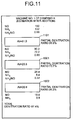
- Fig. 11 is a schematic diagram for explaining another simulation example of the addition (increase) of a denitration catalyst
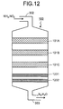
- Fig. 12 is a schematic diagram of still another configuration of the exhaust-gas denitration system
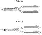
- Fig. 13 is a schematic diagram for explaining an alteration processing for the denitration catalyst
- Fig. 14 is a schematic diagram for explaining another alteration processing for the denitration catalyst
- Fig. 15 is a schematic diagram for explaining another functional configuration of the apparatus for managing a denitration catalyst according to the embodiment of the present invention.
- Fig. 1 is a schematic diagram for explaining an outline of a method for managing a denitration catalyst according to the embodiment of the present invention.
- a periodic maintenance management for a plurality of denitration catalysts 101 in an exhaust-gas denitration system 100 is performed.
- a daily management of the denitration catalysts 101 based on measurement values obtained by a measuring device 102 that measures performance of the respective denitration catalysts 101 is performed.
- step S130 Based on data obtained by the periodic maintenance management (step S110) and the daily management (step S120), secular change data on the denitration catalysts 101 in each unit is managed. Thus, the secular change is managed and a performance variation prediction until a next periodic check is executed (step S130).
- step S140 It is then determined whether a deterioration of each of the denitration catalysts 101 reaches a level at which the performance of the exhaust-gas denitration system 100 cannot be maintained (step S140). If it is determined that the denitration catalyst 101 is deteriorated ("deteriorated" at step S140), the denitration catalyst 101 is regenerated (step S150). Alternatively, the denitration catalyst 101 is exchanged (replaced) with a new one (step S160).
- step S170 a new denitration catalyst is added besides the denitration catalysts 101 (step S170).
- the denitration catalyst may be altered (step S 180). Details of the denitration catalyst addition processing (step S170) and the denitration catalyst alteration processing (step S180) will be explained later.
- step S140 If it is determined that the denitration catalyst 101 is usable ("usable" at step S140), the performance of the exhaust-gas denitration system 100 can be maintained without the need for the replacement or the regeneration of the denitration catalyst 101. No replacement or regeneration is performed, accordingly (step S190).
- a sample catalyst is extracted from each denitration catalyst layer in the exhaust-gas denitration system 100 in each power station.
- a catalyst performance test and a deterioration factor identification are carried out to the sample catalyst. More specifically, a performance test and a surface analysis are performed and evaluated for each sample catalyst.
- An execution target is each power station unit in which the exhaust-gas denitration system 100 is disposed. A measurement is made at each periodic check or during each long-term suspension of operation. It is thereby possible to accurately grasp a greatly deteriorated catalyst.
- a denitration ratio, an SO 2 oxidization ratio, and the like are detected by the test.
- Examples of a method for a catalyst analysis include a catalyst surface analysis (using an X-ray microanalyzer) for measuring a deteriorated matter on the catalyst surface and grasping the performance deterioration, and a catalyst component analysis (an X-ray fluorescent analysis) for measuring the deteriorated matter accumulated in catalyst components and grasping the performance deterioration.
- a catalyst surface analysis using an X-ray microanalyzer
- a catalyst component analysis an X-ray fluorescent analysis
- a performance test for the exhaust-gas denitration system 100 is performed (step S121) at each power station.
- An execution target is each power station unit in which the exhaust-gas denitration system 100 is disposed, and an exhaust gas of each of the catalyst layers is measured.
- the measurement frequency is about once or twice per year.
- the regeneration of the denitration catalyst 101 specifically is regeneration of the deteriorated catalyst based on a secular performance variation prediction.
- regeneration timing and a target catalyst (layer) are selected, and an optimum regeneration work is selected, prepared, and executed. Further, a regenerated catalyst activation test is performed thereby managing a performance recovery ratio.
- the denitration catalysts 101 can be efficiently managed.
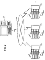
- FIG. 2 is a schematic diagram for explaining a system configuration of the denitration catalyst management system including the apparatus for managing a denitration catalyst according to the embodiment of the present invention.
- measuring devices 102a, 102b, 102c... respectively connected to exhaust-gas denitration systems 100a, 100b, 100c, ... disposed in each of a plurality of power station units are connected to an apparatus for managing a denitration catalyst 201 serving as a centralized management center through a network 200 such as the Internet.
- the apparatus for managing a denitration catalyst 201 can, therefore, mutually communicate data with each of the measuring devices 102 through the network 200.
- the apparatus for managing a denitration catalyst 201 can receive information on the performance of the denitration catalysts 101 measured by each of the measuring devices 102 when necessary.
- the apparatus for managing a denitration catalyst 201 can transmit, to each of the measuring devices 102 or to an administrator of each of the exhaust-gas denitration systems 100, information on a timing of processings (a regeneration processing and a replacement processing) for each of the denitration catalysts 101 or the like, information on a charge amount required for management to be explained later, and the like.
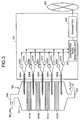
- Fig. 3 is a schematic diagram of a configuration of the exhaust-gas denitration system and the configuration of the measuring device. While the exhaust-gas denitration system 100 is provided in the thermal power station, an installation location of the exhaust-gas denitration system 100 according to this embodiment is not limited to the thermal power station.
- the exhaust-gas denitration system 100 includes an exhaust duct 302 connected to an upstream side of a system main body 301 and communicating with a boiler device of the thermal power station and a processing gas duct 303 connected to a downstream side of the system main body 301.
- denitration catalysts 101A to 101D in a plurality of layers (four layers) are arranged at predetermined intervals. Each of the denitration catalysts 101A to 101D is provided in such a manner that an exhaust gas introduced from the exhaust duct 302 can be sequentially passed through the denitration catalysts 101A to 101D.
- each of the denitration catalyst 101 contacts with the exhaust gas having passed therethrough, and a nitrogen oxide (NO x ) contained in the exhaust gas can be reduced.
- NO x nitrogen oxide
- NH 3 is injected depending on an amount of the exhaust gas from a boiler main body.
- Types, shapes, and the like of each of the denitration catalysts 101A to 101D are not limited. Generally, TiO 2 is used as a carrier, V 2 O 5 is used as an active component, and a honeycomb type, a plate type, or the like is used as a catalyst type. Alternatively, the denitration catalyst that contains WO 3 or M 0 O 3 as a co-catalyst component may be used or the denitration catalyst that does not contain the co-catalyst component may be used. In this embodiment, honeycomb denitration catalysts are used and a plurality of columnar honeycomb type catalysts are arranged, thereby constituting each of the denitration catalysts 101A to 101D.
- the measuring device 102 is provided with gas extracting units 305A to 305E at inlets and outlets for each of the denitration catalysts 101A to 101D.
- the gas extracting units 305A to 305E are connected to NO x concentration measuring units 306A to 306E and NH 3 concentration measuring units 307A to 307E respectively.
- Information on measurement results obtained by the NO x concentration measuring units 306A to 306E and the NH 3 concentration measuring units 307A to 307E is transmitted to a denitration ratio measuring unit 308 that calculates a denitration ratio and a denitration burden ratio of each of the denitration catalysts 101A to 101D.
- the gas extracting units 305A to 305E extract sampling gases in desired amounts through sampling tubes at a desired timing, and supply the sampling gases extracted to the NO x concentration measuring units 306A to 306E and the NH 3 concentration measuring units 307A to 307E, respectively.
- the gas extracting units 305A to 305E are configured to supply the extracted gases to the NO x concentration measuring units 306A to 306E and the NH 3 concentration measuring units 307A to 307E, respectively.
- the gas extracting units may be independently provided in the NO x concentration measuring units 306A to 306E and the NH 3 concentration measuring units 307A to 307E, respectively.
- the sampling gas extraction timing at which the gas extracting units 305A to 305E extract the sampling gases is not specifically limited. However, the extraction is performed preferably during a normal operation of the corresponding power station, more preferably during a rated load time at which the amount of gas reaches a maximum.
- each NH 3 concentration is reduced and a fluctuation width of the NH 3 concentration increases. In order to improve a management evaluation, therefore, it is preferable to increase the number of times of measuring the NH 3 concentration and to calculate the denitration ratio from an average concentration. Alternatively, the number of times of measuring the NH 3 concentration may be changed for each denitration catalyst.
- the NO x concentration measuring units 306A to 306E and the NH 3 concentration measuring units 307A to 307E are not specifically limited as long as they measure the NO x concentrations and the NH 3 concentrations in the sampling gases, respectively. Sensors that measure the NO x concentrations and the NH 3 concentrations may be used, and each sampling gas may be extracted either by an automatic measuring device or manually, and the extracted sampling gas may be analyzed. As for the sampling gas, concentrations of oxygen and other components may be measured besides the NO x concentration and the NH3 concentration when necessary.
- one unit of the NO x concentration measuring unit and one unit of the NH 3 concentration measuring unit may be provided to sequentially analyze concentrations at the inlets and the outlets of the denitration catalysts 101A to 101D.
- the denitration ratio measuring unit 308 acquires measurement results from the NO x concentration measuring units 306A to 306E and the NH 3 concentration measuring units 307A to 307E, and calculates denitration ratios and denitration burden ratios of the respective denitration catalysts 101A to 101D from these measurement results.
- Functions of the denitration ratio measuring unit 308 are realized by, for example, making a CPU execute programs stored in a ROM, a RAM, a hard disk or the like, not shown.
- the reason for considering the inlet mole ratio is as follows. Since NH 3 is injected just before injection of the denitration catalyst in proportion to an amount of gas and absorption of NH 3 to the catalyst is a rate-determining reaction of a denitration reaction itself, it is necessary to grasp and consider the NH 3 concentration of each of the denitration catalysts 101A to 101D at the inlet and the outlet therefor.
- the ratio may be calculated based on either NO x or NH 3 . However, if the denitration ratio is calculated based on NH 3 , the denitration ratio can be managed more accurately.
- the evaluation mole ratio is set to evaluate the denitration catalyst and can be set at an appropriate mole ratio, for example, at about an operational mole ratio of the power station, e.g., 0.8.
- the denitration ratio ⁇ obtained from the equation (1) is calculated based on the NO x concentration. Since the inlet mole ratio is considered in the equation (1), the catalyst can be evaluated based on the practical denitration ratio.
- the denitration ratio ⁇ obtained from the equation (2) is calculated based on the NH 3 concentration, and a more stable numeric value of the denitration ratio can be advantageously obtained than that calculated based on the NO x . Therefore, the evaluation of the catalyst can be more stably performed.
- a transmitter 309 transmits measurement data obtained by the denitration ratio measuring unit 308 to the apparatus for managing a denitration catalyst 201 through the network 200.
- Functions of the transmitter 309 are realized with, for example, an interface such as a modem, not shown.
- the operational information can be appropriately provided to a catalyst user.
- the NO x measurement results obtained by an already disposed online chemiluminescent analyzer or the like can be transmitted through the network shown in Fig. 2.
- NH 3 measurement data obtained by a device that oxidizes NH 3 (ammonia) into NO and that measures the converted NO by chemiluminescence or the like using an indirect measuring method, a device using an infrared or ultraviolet absorption method that is a direct measuring method for directly measuring gaseous ammonia, a device using a measurement method in conformity to JIS for directly measuring gaseous ammonia or ammonia adhering to dust, an automatic analyzer in conformity to JIS, or the like can be transmitted.
- the transmitted measurement data is centralized and managed by the apparatus for managing a denitration catalyst 201 serving as a data management center.
- the performance of the respective layers can be grasped and managed by calculating the denitration ratios in consideration of ammonia/NO x concentrations since a reaction ratio changes according to a ratio of ammonia to NO x concentrations in the management.
- the measurement may be made once or more per day.
- Fig. 4 is a schematic diagram of a functional configuration of the apparatus for managing a denitration catalyst according to the embodiment of the present invention.
- the apparatus for managing a denitration catalyst 201 includes a receiver 401, a performance information database 402, a determining unit 403, an output unit 404, a denitration catalyst management information database 405, a cost information database 406, and a charge amount determining unit 407.
- the receiver 401 receives measurement data (i.e., information on the performance of the denitration catalyst 101) transmitted from the measuring device 102, more specifically, from the transmitter 309 of the measuring device 102 shown in Fig. 3, through the network 200. Functions of the receiver 401 are realized by the interface such as the modem, not shown.
- the performance information database 402 stores the measurement data received by the receiver 401 for each of the denitration catalysts 101 in each of the exhaust-gas denitration system 100.
- the data stored in the performance information database 402 includes not only the measurement data received by the receiver 401 but also data on a utilization status of each of the denitration catalysts 101 (a history as to which layer of the exhaust-gas denitration system 100 the denitration catalyst 101 is used as, when, how often, and by what method the denitration catalyst 101 is regenerated, and the like).
- Functions of the performance information database 402 are realized with, for example, a recording medium such as a hard disk, not shown.
- the determining unit 403 determines which processing is performed for the denitration catalyst 101, the regeneration processing or the replacement processing, or whether none of the regeneration processing and the replacement processing are performed for each denitration catalyst 101 based on the information relating on the performance of the denitration catalyst 101 stored in the performance information database 402. Further, the determining unit 403 selects an optimum regeneration processing from among a plurality of types of regeneration processings if determining that the regeneration processing for the denitration catalyst 101 is performed. Detailed procedures in relation to the determination and the selection of the optimum regeneration processing will be explained later.
- the determining unit 403 can determine whether the denitration catalyst 101 is replaced with a denitration catalyst that has been used in an exhaust-gas denitration system other than the determination target exhaust-gas denitration system 100 and that has been subjected to the regeneration processing.
- a denitration catalyst that has been used in an exhaust-gas denitration system other than the determination target exhaust-gas denitration system 100 and that has been subjected to the regeneration processing.
- the determining unit 403 can also determine whether to alter the shape of the replacement target denitration catalyst.
- the determining unit 403 can also determine whether to alter the shape of the regeneration target denitration catalyst 101.
- the determining unit 403 further determines whether at least one of the regeneration processing for the denitration catalyst 101, the replacement processing for the denitration catalyst 101, or the addition processing for adding a new denitration catalyst is performed or whether none of the processings are performed, based on the information on the performance of the denitration catalyst 101 stored in the performance information database 402.
- the determining unit 403 can also determine whether to add the denitration catalyst that has been used in another exhaust-gas denitration system and that has been subjected to the regeneration processing.
- the determining unit 403 may determine whether to alter the shape of the addition target denitration catalyst.
- the determining unit 403 determines the execution timing of the regeneration processing for each denitration catalyst 101 or the replacement processing therefor based on the information on the performance of the denitration catalyst 101 stored in the performance information database 402 for each denitration catalyst. Alternatively, the determining unit 403 may determine the execution timing of the regeneration processing for the denitration catalyst 101, the replacement processing therefor, or the addition processing for the new denitration catalyst based on the information on the performance of the denitration catalyst 101 stored in the performance information database 402 for each denitration catalyst.
- Functions of the determining unit 403 are realized by making the CPU execute programs stored in, for example, the ROM, the RAM, or the hard disk, not shown.
- the output unit 404 registers results obtained by the determining unit 403 in the denitration catalyst management information database 405 or transmits them to a predetermined transmission destination through the network 200.
- the charge amount determining unit 407 registers and transmits information on a determined charge amount. Functions of the output unit 404 are realized by making the CPU execute programs stored in, for example, the ROM, the RAM, or the hard disk, not shown, or by the interface such as the modem, not shown.
- the denitration catalyst management information database 405 registers and manages, as denitration catalyst management information, the results obtained by the determining unit 403 for each denitration catalyst 101. Functions of the denitration catalyst management information database 405 are realized with, for example, the recording medium such as the hard disk, not shown.
- the cost information database 406 stores information on costs required for the regeneration processing and the replacement processing. Functions of the cost information database 406 are realized with, for example, the recording medium such as the hard disk, not shown.
- the charge amount determining unit 407 determines, as a charge amount, an amount of money at a predetermined ratio to a difference between the cost required for the replacement processing and the cost required for the regeneration processing, if the determining unit 403 determines that the regeneration processing is performed.
- a new accounting system that checks for a deterioration status of the denitration catalyst and that charges a client that desires performance assurance with a cost according to a deterioration factor, a deterioration degree, or the like can be constituted.
- the charge amount determining unit 407 may determine the charge amount from a user of the exhaust-gas denitration system based on costs required for an installation processing for the denitration catalysts and the management thereof. Specifically, the charge amount determining unit 407 determines the charge amount by, for example, multiplying the costs by a predetermined coefficient. It is thereby possible to rent out denitration catalysts to facilities such as a thermal power station or a waste incinerator having denitration systems, execute the periodic maintenance management and the daily management to perform an NO x treatment for the power station, and collect a rental fee calculated from the catalyst installation cost and the management cost for the processing.
- Functions of the charge amount determining unit 407 are realized by, for example, making the CPU execute programs stored in the ROM, the RAM, or the hard disk, not shown.
- the "periodic maintenance” refers to a periodic check or a long-term suspension of operation.
- Real denitration catalysts are extracted from those within the exhaust-gas denitration system 100 during the periodic maintenance, and the performance of each denitration catalyst 101 is checked.
- the performance of the denitration catalyst is the denitration ratio, or an SO 2 oxidization ratio or an SO 3 conversion ratio (hereinafter, "SO 2 oxidation ratio").
- SO 2 oxidation ratio By thus checking the performance of the denitration catalyst 101, a deterioration factor for the denitration catalyst 101 is grasped. In addition, a deteriorated region within one unit of the denitration catalyst 101 is also grasped.
- a purpose of grasping the performance of the denitration catalyst 101 is to grasp the denitration ratio or the SO 2 oxidation ratio under ideal or standard conditions. If it is grasped, a performance deterioration caused by the catalyst itself can be determined. In the actual exhaust-gas denitration system 100, the performance quality sometimes depends on various factors. Examples of the various factors include gas properties of dust, an injection state of NH 3 serving as a reducer, and a gas flow.
- the measured performance of the denitration catalyst 101 enables estimating the catalyst performance in the actual system by adjusting an AV (area velocity), an LV (linear velocity), or the like to the actual system.
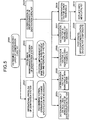
- Fig. 5 is a schematic diagram for explaining details of determination for a denitration catalyst layer, which is deteriorated, in the method for managing a denitration catalyst according to the embodiment of the present invention.
- deterioration level of the system 100 or the most deteriorated layer is determined based on the performance of the catalyst of each layer extracted at the previous periodic maintenance and the performance of each layer obtained by gas measurement (daily management) using a graph shown in Fig. 6 or the like (step S500).
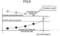
- Fig. 6 is a schematic diagram (graph) for explaining a change in a design denitration ratio to an operating time and a change in an unreacted (leak) NH 3 .
- a normal operation is recommended or a specification change is recommended if necessary.
- the operational problem is, for example, a use of the exhaust-gas denitration system 100 under conditions exceeding a design specification thereof, a use of the exhaust-gas denitration system 100 at a mole ratio exceeding a design NH 3 /NO x (mole ratio), and a use of the exhaust-gas denitration system 100 without modifying operation to be suitable for a fuel changed (change from low sulfur fuel oil to high sulfur fuel oil).
- step S502 When the determination result at step S500 indicates that the deterioration is due to a problem in maintenance and design of the denitration system (step S502), for example, insufficient maintenance for the exhaust-gas denitration system 100, deficiency in the specification or design of the catalyst components of the denitration catalyst 101, then improvement of maintenance in a part at which maintenance is insufficient, and removal of such factor are proposed.
- the insufficient maintenance for the exhaust-gas denitration system 101 is, for example, insufficient injection of NH 3 (because of nozzle clogging or the like), a reduction in a reactive area due to accumulation of dust caused by a gas flow rate flow change, and erosion.
- the deficiency in the specification or design of the catalyst components of the denitration catalyst 101 is for example, a failure to select the catalyst components suitable for the processing exhaust gas, and the dust clogging due to arrangement of the catalysts (pileup of the honeycomb type catalysts).
- One of the proposals for the improvement of the insufficient maintenance part and the removal of the factor may be made for of an optimum catalyst length (about 300 to 500 mm for a honeycomb catalyst at a pitch of 7 mm), in view of the fact that the current SV-base design often results in an over-specification.
- step S503 When the determination result at step S500 indicates that the deterioration is caused by deterioration in the performance of the denitration catalyst (step S503), the regeneration processing is performed (steps S504 to S508) with a view of removing the deterioration factor.
- the regeneration processing if only the inlet side is deteriorated irrespectively of the deterioration factor (step S504), the deteriorated catalyst layer is reset by reversing a gas flow direction, whereby the deteriorated catalyst layer can be removed. Alternatively, a deteriorated region may be removed (cut off or separated) and the catalyst layer may be then reset.
- the deteriorated denitration catalyst layer is washed and regenerated, and then reset. If the denitration catalyst 101 is physically fragile, the denitration catalyst layer may be washed and regenerated while the denitration catalyst layer is set within the exhaust-gas denitration system 100.
- the deterioration factor is removable with chemicals (step S506), that is, if the deterioration factor (for example, vanadium) is not removable with water, the deterioration factor is cleaned and regenerated using chemicals such as oxalic acid. Further, after the cleaning with the chemicals, the deterioration factor may be dried or heated so as to recover the performance of the catalyst. In addition, treatments for generated waste liquid and waste matter are executed.
- the deterioration factor for example, vanadium
- step S507 If the deterioration factor is removable by abrasion (step S507), that is, the deterioration factor is not removable with the washing or chemical treatment, the catalyst surface is abraded and regenerated using an abrasive or abrasive grains.
- this method entails a physical wear by scraping the catalyst itself, is not suitable for repeated regeneration.
- step S508 If the deterioration factor is not removable (step S508), the catalyst components are subjected to re-impregnation (re-coating) (step S509). That is, the deteriorated catalyst is not disposed of but is kept as it is or crushed down, and the catalyst components are re-adjusted, thereby regenerating and reusing them.
- the deteriorated catalyst is replaced with a new catalyst (step S510).
- the deteriorated catalyst is disposed of and is replaced with a new catalyst. It is noted, however, that the length of the catalyst is adjusted to be optimum and a replacing catalyst is provided to the user at a low price.
- Fig. 7 is a schematic diagram (graph) for explaining secular change management and performance variation prediction.
- the apparatus for managing a denitration catalyst 201 manages the secular change in the information on the performance of each of the denitration catalysts 101 including information on the leak NH 3 , whereby the device 201 can make a future performance prediction.
- the device 201 can determine execution timing for the regeneration processing for the denitration catalysts 101 or execution timing for the replacement processing for each of the denitration catalyst 101.
- Fig. 8 is a schematic diagram for explaining a merit of regeneration of the denitration catalyst 101.
- a predicted merit when the denitration catalysts are replaced with regenerated catalysts instead of a new catalyst is shown in Fig. 8.
- a power station output is 500 megawatts.
- a catalyst amount is about 724 cubic meters (181 m 3 /layer).
- the number of catalyst layers is 4.
- the number of catalysts is 37,440 (9,360 catalysts/layer), and a catalyst unit price is 3 million to 4 million yen.
- a merit of about 100 million yen/year per unit is predicted for a ten-year balance. Even if costs of the daily management (5 million yen/year per unit) and the cost for catalyst performance check (10 million yen/2 years per unit) during the periodic maintenances are subtracted from the merit, a merit of about 90 million yen/year per unit is predicted.
- Fig. 9 is a schematic diagram of another configuration of the exhaust-gas denitration system.
- the exhaust-gas denitration system 100 shown in Fig. 9 is provided with a new denitration catalyst 901 above the denitration catalyst 101A.
- a processing performance of the exhaust-gas denitration system 100 can be improved without performing the replacement processing or the regeneration processing for the denitration catalysts 101A to 101D.
- the addition processing may be performed together with the replacement processing or the regeneration processing for the denitration catalysts 101A to 101D.
- the added denitration catalyst 901 is installed above the denitration catalyst 101A.
- an installation location is not limited thereto.
- the added denitration catalyst 901 may be, therefore, provided below the denitration catalyst 101D or between the denitration catalysts, for example.
- the number of the denitration catalyst 901 to be added is just one.
- the number of the denitration catalysts 901 is not limited to one and may be two or more.
- Figs. 10 and 11 are schematic diagrams for explaining a simulation example of an addition (increase) of the denitration catalyst.
- Figs. 10 and 11 an example of adding a denitration catalyst 1101 above denitration catalysts 1001 and 1002 is shown.
- “NO” is reduced from '20.3' to '18.9'
- "NH 3 " is reduced from '2.3' to '0.9'
- “total denitration ratio” is improved from '86.5%' to '87.4%'.
- an effect of the denitration catalyst addition processing can be clearly displayed.
- Fig. 12 is a schematic diagram of still configuration of the exhaust-gas denitration system.
- the exhaust-gas denitration system 100 shown in Fig. 12 differs from the exhaust-gas denitration system 100 shown in Fig. 3 in that the shape of the denitration catalyst 101D is altered when the regeneration processing for the denitration catalyst 101D is performed.
- Figs. 13 and 14 are schematic diagrams for explaining the alteration processing for the denitration catalyst 101D.
- the alteration processing is specifically cutting of the denitration catalyst 101D in parallel to a plane surface into two denitration catalysts 1201 and 1202.
- the denitration catalysts 1201 and 1202 are installed in the exhaust-gas denitration system 100 while a predetermined distance is kept therebetween.
- the denitration catalysts 1201 and 1202 are substantially equal in width ("w" for both the denitration catalysts 1201 and 1202).
- the denitration catalyst 101D may be cut and separated so that a width of the denitration catalyst 1201 (the width "w 1 ") and a width of the denitration catalyst 1202 (the width "w 2 ") differ ("w 1 ">"w 2 ").
- the respective widths are changed according to the position or the like of the denitration catalyst to be altered, the alteration processing can be performed more efficiently.
- the alteration processing may include not only cutting in parallel to the plane surface but also cutting and separation of the denitration catalyst perpendicularly to the plane surface, or at an arbitrary angle.
- the denitration catalyst may be cut into not two but three or more. While the alteration processing is performed during the regeneration processing in the above explanation, only the alteration processing may be performed without performing the regeneration processing. Alternatively, the same alteration processing may be performed during not the regeneration processing but the replacement processing.
- Fig. 15 is a schematic diagram for explaining another functional configuration of the apparatus for managing a denitration catalyst according to an embodiment of the present invention.
- like reference numerals designate like constituent elements as those shown in Fig. 4, and they will not be explained herein.
- the determination is made based on the measurement result of the denitration catalysts in the management target exhaust-gas denitration system.
- the denitration catalysts in the management target exhaust-gas denitration system are not measured. Instead, the performance of the management target denitration catalysts in the exhaust-gas denitration system are predicted from information on management of the other exhaust-gas denitration systems, and management is performed based on the prediction.
- the apparatus for managing a denitration catalyst 201 includes the receiver 401, the performance information database 402, the determining unit 403, the output unit 404, the denitration catalyst management information database 405, the cost information database 406, the charge amount determining unit 407, and an input unit 1501.
- the input unit 1501 accepts input of information on an equipment scale and an operating time of exhaust-gas denitration system, of which the performance is to be predicted. Specifically, functions of the input unit 1501 are realized with a pointing device such as a keyboard or a mouse, not shown. Alternatively, the information may be input to the receiver 401 through the network 200.
- the determining unit 403 predicts the performance of the denitration catalysts in the exhaust-gas denitration system for each denitration catalyst based on the input information on the equipment scale and the operating time of the exhaust-gas denitration system. During the prediction, information on performance of a plurality of denitration catalysts in the other exhaust-gas denitration systems stored in the performance information database 402, and information on the execution timing of the denitration catalyst regeneration processing, the denitration catalyst replacement processing, or the new denitration catalyst addition processing determined based on the performance information and stored in the denitration catalyst management information database 405 are used.
- the execution timing of the denitration catalyst regeneration processing, the denitration catalyst replacement processing, or the new denitration catalyst addition processing is determined for each denitration catalyst.
- a result of the determination is output by the output unit 404, or stored in the denitration catalyst management information database.
- the performance of the denitration catalysts 101 are measured for each of the denitration catalyst 101. Based on the measured performance, determination is made as to which of the processings is to be performed, the regeneration processing for the denitration catalysts 101 or the replacement processing therefor, or determination is made on whether neither of the processings is performed, for each denitration catalyst 101.
- the performance of the denitration catalysts 101 can be grasped for each denitration catalyst 101, and an appropriate processing can be carried out for each denitration catalyst 101 based on the grasped performance. It is, therefore, possible to efficiently and cost-effectively manage the denitration catalysts 101.
- the optimum regeneration processing is selected from among a plurality of regeneration processings when the regeneration processing for the denitration catalysts 101 is performed based on the measured performance. It is, therefore, possible to more efficiently and more cost-effectively manage the denitration catalysts.
- a plurality of denitration catalysts 101 including those in the exhaust-gas denitration systems in the power stations suspended or discontinued are managed comprehensively and intensively using the network.
- the denitration catalyst 101 is replaced by the denitration catalyst that has been used in the other exhaust-gas denitration system and that has been subjected to the regeneration processing. It is, therefore, possible to facilitate management for more appropriate replacement of the denitration catalyst 101, and suppress total cost.
- the present invention if it is determined to perform the regeneration processing, it is possible to charge the user the amount of money at the predetermined ratio to the difference between the cost required for the replacement processing and the cost required for the regeneration processing.
- denitration catalysts are owned, and the owned denitration catalysts are rented out to facilities including the denitration systems such as the thermal power station or the waste incinerator.
- the periodic maintenance management and the daily management for the rented denitration catalysts are executed to carry out the NO x treatment for the power station.
- the used denitration catalyst may be a new or a regenerated catalyst. All the managements and the checks are executed to ensure a hedge (to avoid risk) against the NO x treatment.
- a rental fee calculated from the denitration catalyst installation cost and the management cost can be collected. As a result, a long-term rental contract enables the user to take environmental measures at lower cost than that required to purchase the denitration catalysts.
- the execution timing of the regeneration processing for the denitration catalysts 101 or the replacement processing therefor is determined for each denitration catalyst 101 based on the measured performance. By notifying the regeneration or replacement timing in advance, efficient measures for the processing can be taken.
- the exhaust gas is measured for each denitration catalyst 101 at the inlet and the outlet therefor.
- the sample of each denitration catalyst 101 is extracted and the performance of the extracted sample is measured. Therefore, it is possible to acquire more accurate information on the performance of the denitration catalysts 101.
- the performance of the management target denitration catalysts in the exhaust-gas denitration system are predicted based on the already measured data on the denitration catalysts in the other exhaust-gas denitration systems. It is, therefore, unnecessary to measure the performance of the management target exhaust-gas denitration system. Accordingly, it is unnecessary to separately provide facilities for the measurement and take labor and time for the measurement.
- the present invention advantageously provides the method and the apparatus for managing a denitration catalyst that can comprehensively and intensively manage a denitration catalyst, and ensure efficient and cost-effective management for the denitration catalyst including regeneration and replacement therefor.
- the present invention is suitable for a method and an apparatus for managing a denitration catalyst that perform maintenance for denitration catalysts including regeneration, replacement, addition, and alteration by managing the denitration catalysts in an exhaust-gas denitration system.
Landscapes
- Engineering & Computer Science (AREA)
- Chemical & Material Sciences (AREA)
- Environmental & Geological Engineering (AREA)
- Chemical Kinetics & Catalysis (AREA)
- Biomedical Technology (AREA)
- Analytical Chemistry (AREA)
- General Chemical & Material Sciences (AREA)
- Oil, Petroleum & Natural Gas (AREA)
- Health & Medical Sciences (AREA)
- Materials Engineering (AREA)
- Organic Chemistry (AREA)
- Combustion & Propulsion (AREA)
- Exhaust Gas Treatment By Means Of Catalyst (AREA)
- Treating Waste Gases (AREA)
- Exhaust Gas After Treatment (AREA)
- Catalysts (AREA)
Applications Claiming Priority (3)
| Application Number | Priority Date | Filing Date | Title |
|---|---|---|---|
| JP2002320390A JP3935417B2 (ja) | 2002-11-01 | 2002-11-01 | 脱硝触媒管理方法および脱硝触媒管理装置 |
| JP2002320390 | 2002-11-01 | ||
| PCT/JP2003/013952 WO2004043575A1 (ja) | 2002-11-01 | 2003-10-30 | 脱硝触媒管理方法および脱硝触媒管理装置 |
Publications (3)
| Publication Number | Publication Date |
|---|---|
| EP1557219A1 true EP1557219A1 (de) | 2005-07-27 |
| EP1557219A4 EP1557219A4 (de) | 2005-11-16 |
| EP1557219B1 EP1557219B1 (de) | 2016-01-06 |
Family
ID=32310349
Family Applications (1)
| Application Number | Title | Priority Date | Filing Date |
|---|---|---|---|
| EP03770045.7A Expired - Lifetime EP1557219B1 (de) | 2002-11-01 | 2003-10-30 | Denitrierungskatalysatorverwaltungsverfahren |
Country Status (11)
| Country | Link |
|---|---|
| US (2) | US7875459B2 (de) |
| EP (1) | EP1557219B1 (de) |
| JP (2) | JP3935417B2 (de) |
| KR (1) | KR100695972B1 (de) |
| CN (1) | CN1708346B (de) |
| AU (1) | AU2003280652A1 (de) |
| CA (1) | CA2502482C (de) |
| DK (1) | DK1557219T3 (de) |
| HU (1) | HUE027194T2 (de) |
| TW (1) | TWI229616B (de) |
| WO (1) | WO2004043575A1 (de) |
Cited By (2)
| Publication number | Priority date | Publication date | Assignee | Title |
|---|---|---|---|---|
| EP1579913A4 (de) * | 2002-12-27 | 2009-06-10 | Chugoku Electric Power | Wabenkatalysator, denitrierungskatalysator einer denitrierungsvorrichtung und abgasdenitrierungsvorrichtung |
| FR2949353A1 (fr) * | 2009-08-28 | 2011-03-04 | Lab Sa | Procede de determination et de suivi de l'activite d'un catalyseur de denitrification |
Families Citing this family (14)
| Publication number | Priority date | Publication date | Assignee | Title |
|---|---|---|---|---|
| DK1762844T3 (en) | 2004-06-28 | 2014-12-15 | Chugoku Electric Power | A method of testing a denitreringskatalysator |
| KR101123543B1 (ko) * | 2009-08-28 | 2012-03-13 | (주)이엠엔씨코리아 | 활성탄 샘플 채취장치가 구비된 활성탄 흡착탑 |
| JP5289364B2 (ja) * | 2010-03-17 | 2013-09-11 | 中国電力株式会社 | ハニカム触媒の研磨評価装置 |
| JP5701185B2 (ja) | 2011-09-09 | 2015-04-15 | 三菱重工業株式会社 | 脱硝触媒のso2酸化率上昇低減方法 |
| US9297286B2 (en) * | 2011-11-01 | 2016-03-29 | Cummins Emission Solutions Inc. | Aftertreatment system for an engine |
| JP6000083B2 (ja) * | 2012-11-16 | 2016-09-28 | 三菱重工業株式会社 | 排ガス脱硝システム |
| JP6245405B2 (ja) * | 2015-07-31 | 2017-12-13 | 中国電力株式会社 | 脱硝触媒の劣化評価方法 |
| WO2018100368A1 (en) * | 2016-12-01 | 2018-06-07 | Johnson Matthey Public Limited Company | METHOD OF EXTENDING THE USEFUL LIFE OF AN AGED SCR CATALYST BED IN AN EXHAUST SYSTEM OF A STATIONARY SOURCE OF NOx |
| JP6848598B2 (ja) * | 2017-03-29 | 2021-03-24 | 中国電力株式会社 | 脱硝触媒の再利用方法 |
| CN109426144B (zh) * | 2017-08-22 | 2021-07-16 | 邢台国泰发电有限责任公司 | 基于随机森林模型的电站锅炉烟气脱硝方法 |
| JP7657071B2 (ja) * | 2021-02-26 | 2025-04-04 | 三菱重工業株式会社 | 脱硝装置の触媒配置決定方法及び脱硝装置のメンテナンス方法並びに脱硝装置、ボイラ、及び発電プラント |
| US11846971B2 (en) * | 2021-10-27 | 2023-12-19 | International Business Machines Corporation | Unexpected device usage detection and adaptation |
| CN115957603A (zh) * | 2022-12-07 | 2023-04-14 | 国电环境保护研究院有限公司 | 脱硝系统监控装置及脱硝系统监控系统 |
| JP2024103993A (ja) * | 2023-01-23 | 2024-08-02 | トヨタ自動車株式会社 | 性能予測装置 |
Family Cites Families (17)
| Publication number | Priority date | Publication date | Assignee | Title |
|---|---|---|---|---|
| JPS5912115A (ja) * | 1982-07-13 | 1984-01-21 | Samukomu Electron Kk | 自動車排ガス浄化用触媒 |
| JPH0615015B2 (ja) * | 1984-11-12 | 1994-03-02 | バブコツク日立株式会社 | 触媒サンプリング装置 |
| JPS61227846A (ja) | 1985-04-01 | 1986-10-09 | Mitsubishi Heavy Ind Ltd | 脱硝触媒の再生方法 |
| EP0262558A1 (de) * | 1986-09-30 | 1988-04-06 | Siemens Aktiengesellschaft | Katalysatoranordnung zur Minderung der Sickoxide in Rauchgasen |
| JPH01139146A (ja) * | 1987-08-14 | 1989-05-31 | Mitsubishi Heavy Ind Ltd | 砒素分による劣化脱硝触媒の再生方法及び同装置 |
| JPS6480429A (en) | 1987-09-21 | 1989-03-27 | Mitsubishi Heavy Ind Ltd | Maintenance assisting device of flue-gas denitration equipment |
| JPH01242127A (ja) | 1988-03-18 | 1989-09-27 | Mitsubishi Heavy Ind Ltd | 排煙脱硝プリントの性能管理装置 |
| JPH0747108B2 (ja) | 1991-05-14 | 1995-05-24 | 九州電力株式会社 | 火力発電所排煙脱硝装置の触媒管理法 |
| US6199372B1 (en) * | 1996-04-26 | 2001-03-13 | Komatsu Ltd. | Apparatus and method for regenerating NOx catalyst for diesel engine |
| JPH10109018A (ja) | 1996-10-04 | 1998-04-28 | Babcock Hitachi Kk | 排ガス脱硝方法と装置 |
| US5896743A (en) * | 1997-06-24 | 1999-04-27 | Heraeus Electro-Nite International N.V. | Catalyst monitor utilizing a lifetime temperature profile for determining efficiency |
| US6258981B1 (en) * | 1999-02-17 | 2001-07-10 | University Of Florida | Catalytic oxidation of hydrocarbons |
| JP3680727B2 (ja) * | 2000-11-24 | 2005-08-10 | トヨタ自動車株式会社 | 内燃機関の排気浄化装置 |
| JP3750523B2 (ja) | 2000-12-12 | 2006-03-01 | トヨタ自動車株式会社 | 車両用無段変速機の変速制御装置 |
| US6803236B2 (en) * | 2001-08-10 | 2004-10-12 | Delphi Technologies, Inc. | Diagnostic system for monitoring catalyst performance |
| EP1514590A4 (de) * | 2002-06-14 | 2006-03-08 | Chugoku Electric Power | VORRICHTUNG ZUR ÜBERWACHUNG EINES DENITRIERVORRICHTUNGSKATALYSATORS ZUR ENTFERNUNG VON NOx UND VERFAHREN ZUR ÜBERWACHUNG EINES KATALYSATORS ZUR ENTFERNUNG VON NOx |
| JP4578048B2 (ja) | 2002-06-21 | 2010-11-10 | 中国電力株式会社 | 脱硝触媒再生方法 |
-
2002
- 2002-11-01 JP JP2002320390A patent/JP3935417B2/ja not_active Expired - Lifetime
-
2003
- 2003-10-30 EP EP03770045.7A patent/EP1557219B1/de not_active Expired - Lifetime
- 2003-10-30 CN CN2003801022012A patent/CN1708346B/zh not_active Expired - Fee Related
- 2003-10-30 CA CA002502482A patent/CA2502482C/en not_active Expired - Fee Related
- 2003-10-30 US US10/532,830 patent/US7875459B2/en not_active Expired - Fee Related
- 2003-10-30 HU HUE03770045A patent/HUE027194T2/en unknown
- 2003-10-30 TW TW092130207A patent/TWI229616B/zh not_active IP Right Cessation
- 2003-10-30 JP JP2004551197A patent/JP4429171B2/ja not_active Expired - Lifetime
- 2003-10-30 KR KR1020057007370A patent/KR100695972B1/ko not_active Expired - Fee Related
- 2003-10-30 DK DK03770045.7T patent/DK1557219T3/en active
- 2003-10-30 WO PCT/JP2003/013952 patent/WO2004043575A1/ja not_active Ceased
- 2003-10-30 AU AU2003280652A patent/AU2003280652A1/en not_active Abandoned
-
2009
- 2009-03-26 US US12/411,867 patent/US7871823B2/en not_active Expired - Fee Related
Cited By (3)
| Publication number | Priority date | Publication date | Assignee | Title |
|---|---|---|---|---|
| EP1579913A4 (de) * | 2002-12-27 | 2009-06-10 | Chugoku Electric Power | Wabenkatalysator, denitrierungskatalysator einer denitrierungsvorrichtung und abgasdenitrierungsvorrichtung |
| FR2949353A1 (fr) * | 2009-08-28 | 2011-03-04 | Lab Sa | Procede de determination et de suivi de l'activite d'un catalyseur de denitrification |
| EP2301649A1 (de) * | 2009-08-28 | 2011-03-30 | Lab Sa | Verfahren zur Bestimmung und zur Verfolgung der Aktivität eines Denitrierungskatalysators |
Also Published As
| Publication number | Publication date |
|---|---|
| JP3935417B2 (ja) | 2007-06-20 |
| US7875459B2 (en) | 2011-01-25 |
| KR100695972B1 (ko) | 2007-03-16 |
| TWI229616B (en) | 2005-03-21 |
| CA2502482A1 (en) | 2004-05-27 |
| US20060040397A1 (en) | 2006-02-23 |
| CN1708346B (zh) | 2010-05-05 |
| US7871823B2 (en) | 2011-01-18 |
| US20090187352A1 (en) | 2009-07-23 |
| EP1557219B1 (de) | 2016-01-06 |
| HUE027194T2 (en) | 2016-10-28 |
| JP4429171B2 (ja) | 2010-03-10 |
| TW200413081A (en) | 2004-08-01 |
| EP1557219A4 (de) | 2005-11-16 |
| CN1708346A (zh) | 2005-12-14 |
| DK1557219T3 (en) | 2016-04-11 |
| CA2502482C (en) | 2009-06-23 |
| JPWO2004043575A1 (ja) | 2006-09-21 |
| JP2004154622A (ja) | 2004-06-03 |
| KR20050055791A (ko) | 2005-06-13 |
| AU2003280652A1 (en) | 2004-06-03 |
| WO2004043575A1 (ja) | 2004-05-27 |
Similar Documents
| Publication | Publication Date | Title |
|---|---|---|
| US7871823B2 (en) | Method and apparatus for managing denitration catalyst | |
| EP2543840B1 (de) | Verfahren zur Schätzung des aktuellen Wirkungsgrads von Katalysatoren im Abgasstrang einer Brennkraftmaschine während der Betriebszeit | |
| CN110045054A (zh) | 一种scr脱硝催化剂寿命评估与预测的方法 | |
| CN110580936B (zh) | 中低温scr脱硝催化剂的寿命预测方法及系统 | |
| CN109709260A (zh) | 一种scr脱硝催化剂的全寿命管理方法 | |
| US8980779B2 (en) | Method of regenerating NOx removal catalyst | |
| CN106770890A (zh) | 一种火电厂脱硝催化剂使用寿命的在线评估方法 | |
| US20250232390A1 (en) | METHODS AND SYSTEMS OF ENVIRONMENTAL MONITORING BASED ON INTELLIGENT GAS REGULATORY INTERNET OF THINGS (IoTs) | |
| US7704456B2 (en) | NOx removal catalyst management unit for NOx removal apparatus and method for managing NOx removal catalyst | |
| CA2571044C (en) | Method of testing denitration catalyst | |
| Laudal et al. | Pilot-scale evaluation of the impact of selective catalytic reduction for NOx on mercury speciation | |
| CN110554135B (zh) | 一种基于检测活性的scr脱硝催化剂更换体积量核算方法 | |
| JPH10109018A (ja) | 排ガス脱硝方法と装置 | |
| CN118761887A (zh) | 一种高效自动化医疗垃圾处理系统 | |
| JP3855754B2 (ja) | 触媒の性能予測方法及び性能予測システム | |
| US12071876B1 (en) | Estimating deterioration trends of an exhaust catalyst | |
| CN120521226A (zh) | 一种智能预防空预器堵塞的方法 | |
| CN121808194A (zh) | 一种排污在线检测与排污负荷计算方法及系统 |
Legal Events
| Date | Code | Title | Description |
|---|---|---|---|
| PUAI | Public reference made under article 153(3) epc to a published international application that has entered the european phase |
Free format text: ORIGINAL CODE: 0009012 |
|
| 17P | Request for examination filed |
Effective date: 20050419 |
|
| AK | Designated contracting states |
Kind code of ref document: A1 Designated state(s): AT BE BG CH CY CZ DE DK EE ES FI FR GB GR HU IE IT LI LU MC NL PT RO SE SI SK TR |
|
| AX | Request for extension of the european patent |
Extension state: AL LT LV MK |
|
| A4 | Supplementary search report drawn up and despatched |
Effective date: 20051004 |
|
| DAX | Request for extension of the european patent (deleted) | ||
| 17Q | First examination report despatched |
Effective date: 20110426 |
|
| REG | Reference to a national code |
Ref country code: DE Ref legal event code: R079 Ref document number: 60348432 Country of ref document: DE Free format text: PREVIOUS MAIN CLASS: B01D0053940000 Ipc: B01D0053860000 |
|
| GRAP | Despatch of communication of intention to grant a patent |
Free format text: ORIGINAL CODE: EPIDOSNIGR1 |
|
| RIC1 | Information provided on ipc code assigned before grant |
Ipc: B01D 53/86 20060101AFI20150624BHEP |
|
| INTG | Intention to grant announced |
Effective date: 20150713 |
|
| RIN1 | Information on inventor provided before grant (corrected) |
Inventor name: OKA, Y. Inventor name: SHIMADA, H. |
|
| GRAS | Grant fee paid |
Free format text: ORIGINAL CODE: EPIDOSNIGR3 |
|
| GRAA | (expected) grant |
Free format text: ORIGINAL CODE: 0009210 |
|
| AK | Designated contracting states |
Kind code of ref document: B1 Designated state(s): AT BE BG CH CY CZ DE DK EE ES FI FR GB GR HU IE IT LI LU MC NL PT RO SE SI SK TR |
|
| REG | Reference to a national code |
Ref country code: GB Ref legal event code: FG4D |
|
| REG | Reference to a national code |
Ref country code: CH Ref legal event code: EP |
|
| REG | Reference to a national code |
Ref country code: IE Ref legal event code: FG4D |
|
| REG | Reference to a national code |
Ref country code: AT Ref legal event code: REF Ref document number: 768384 Country of ref document: AT Kind code of ref document: T Effective date: 20160215 |
|
| REG | Reference to a national code |
Ref country code: DE Ref legal event code: R096 Ref document number: 60348432 Country of ref document: DE |
|
| REG | Reference to a national code |
Ref country code: DK Ref legal event code: T3 Effective date: 20160404 |
|
| REG | Reference to a national code |
Ref country code: SE Ref legal event code: TRGR |
|
| REG | Reference to a national code |
Ref country code: NL Ref legal event code: FP |
|
| PG25 | Lapsed in a contracting state [announced via postgrant information from national office to epo] |
Ref country code: FI Free format text: LAPSE BECAUSE OF FAILURE TO SUBMIT A TRANSLATION OF THE DESCRIPTION OR TO PAY THE FEE WITHIN THE PRESCRIBED TIME-LIMIT Effective date: 20160106 Ref country code: ES Free format text: LAPSE BECAUSE OF FAILURE TO SUBMIT A TRANSLATION OF THE DESCRIPTION OR TO PAY THE FEE WITHIN THE PRESCRIBED TIME-LIMIT Effective date: 20160106 Ref country code: GR Free format text: LAPSE BECAUSE OF FAILURE TO SUBMIT A TRANSLATION OF THE DESCRIPTION OR TO PAY THE FEE WITHIN THE PRESCRIBED TIME-LIMIT Effective date: 20160407 |
|
| PG25 | Lapsed in a contracting state [announced via postgrant information from national office to epo] |
Ref country code: PT Free format text: LAPSE BECAUSE OF FAILURE TO SUBMIT A TRANSLATION OF THE DESCRIPTION OR TO PAY THE FEE WITHIN THE PRESCRIBED TIME-LIMIT Effective date: 20160506 |
|
| REG | Reference to a national code |
Ref country code: FR Ref legal event code: PLFP Year of fee payment: 14 |
|
| REG | Reference to a national code |
Ref country code: DE Ref legal event code: R097 Ref document number: 60348432 Country of ref document: DE |
|
| REG | Reference to a national code |
Ref country code: HU Ref legal event code: AG4A Ref document number: E027194 Country of ref document: HU |
|
| PG25 | Lapsed in a contracting state [announced via postgrant information from national office to epo] |
Ref country code: EE Free format text: LAPSE BECAUSE OF FAILURE TO SUBMIT A TRANSLATION OF THE DESCRIPTION OR TO PAY THE FEE WITHIN THE PRESCRIBED TIME-LIMIT Effective date: 20160106 |
|
| PGFP | Annual fee paid to national office [announced via postgrant information from national office to epo] |
Ref country code: NL Payment date: 20160913 Year of fee payment: 14 Ref country code: MC Payment date: 20160912 Year of fee payment: 14 |
|
| PLBE | No opposition filed within time limit |
Free format text: ORIGINAL CODE: 0009261 |
|
| STAA | Information on the status of an ep patent application or granted ep patent |
Free format text: STATUS: NO OPPOSITION FILED WITHIN TIME LIMIT |
|
| PG25 | Lapsed in a contracting state [announced via postgrant information from national office to epo] |
Ref country code: RO Free format text: LAPSE BECAUSE OF FAILURE TO SUBMIT A TRANSLATION OF THE DESCRIPTION OR TO PAY THE FEE WITHIN THE PRESCRIBED TIME-LIMIT Effective date: 20160106 Ref country code: SK Free format text: LAPSE BECAUSE OF FAILURE TO SUBMIT A TRANSLATION OF THE DESCRIPTION OR TO PAY THE FEE WITHIN THE PRESCRIBED TIME-LIMIT Effective date: 20160106 |
|
| PGFP | Annual fee paid to national office [announced via postgrant information from national office to epo] |
Ref country code: FR Payment date: 20160919 Year of fee payment: 14 |
|
| 26N | No opposition filed |
Effective date: 20161007 |
|
| PGFP | Annual fee paid to national office [announced via postgrant information from national office to epo] |
Ref country code: BE Payment date: 20160913 Year of fee payment: 14 |
|
| PGFP | Annual fee paid to national office [announced via postgrant information from national office to epo] |
Ref country code: DK Payment date: 20161012 Year of fee payment: 14 Ref country code: DE Payment date: 20161025 Year of fee payment: 14 Ref country code: IE Payment date: 20161010 Year of fee payment: 14 Ref country code: GB Payment date: 20161026 Year of fee payment: 14 Ref country code: CZ Payment date: 20161012 Year of fee payment: 14 Ref country code: HU Payment date: 20161006 Year of fee payment: 14 Ref country code: CH Payment date: 20161013 Year of fee payment: 14 |
|
| PG25 | Lapsed in a contracting state [announced via postgrant information from national office to epo] |
Ref country code: BG Free format text: LAPSE BECAUSE OF FAILURE TO SUBMIT A TRANSLATION OF THE DESCRIPTION OR TO PAY THE FEE WITHIN THE PRESCRIBED TIME-LIMIT Effective date: 20160406 Ref country code: SI Free format text: LAPSE BECAUSE OF FAILURE TO SUBMIT A TRANSLATION OF THE DESCRIPTION OR TO PAY THE FEE WITHIN THE PRESCRIBED TIME-LIMIT Effective date: 20160106 |
|
| PGFP | Annual fee paid to national office [announced via postgrant information from national office to epo] |
Ref country code: AT Payment date: 20160928 Year of fee payment: 14 Ref country code: SE Payment date: 20161011 Year of fee payment: 14 Ref country code: IT Payment date: 20161024 Year of fee payment: 14 |
|
| PG25 | Lapsed in a contracting state [announced via postgrant information from national office to epo] |
Ref country code: LU Free format text: LAPSE BECAUSE OF NON-PAYMENT OF DUE FEES Effective date: 20161030 |
|
| REG | Reference to a national code |
Ref country code: DE Ref legal event code: R119 Ref document number: 60348432 Country of ref document: DE |
|
| REG | Reference to a national code |
Ref country code: DK Ref legal event code: EBP Effective date: 20171031 |
|
| REG | Reference to a national code |
Ref country code: SE Ref legal event code: EUG |
|
| PG25 | Lapsed in a contracting state [announced via postgrant information from national office to epo] |
Ref country code: CY Free format text: LAPSE BECAUSE OF FAILURE TO SUBMIT A TRANSLATION OF THE DESCRIPTION OR TO PAY THE FEE WITHIN THE PRESCRIBED TIME-LIMIT Effective date: 20160106 Ref country code: MC Free format text: LAPSE BECAUSE OF NON-PAYMENT OF DUE FEES Effective date: 20171031 |
|
| REG | Reference to a national code |
Ref country code: CH Ref legal event code: PL |
|
| REG | Reference to a national code |
Ref country code: NL Ref legal event code: MM Effective date: 20171101 |
|
| REG | Reference to a national code |
Ref country code: AT Ref legal event code: MM01 Ref document number: 768384 Country of ref document: AT Kind code of ref document: T Effective date: 20171030 |
|
| GBPC | Gb: european patent ceased through non-payment of renewal fee |
Effective date: 20171030 |
|
| PG25 | Lapsed in a contracting state [announced via postgrant information from national office to epo] |
Ref country code: TR Free format text: LAPSE BECAUSE OF FAILURE TO SUBMIT A TRANSLATION OF THE DESCRIPTION OR TO PAY THE FEE WITHIN THE PRESCRIBED TIME-LIMIT Effective date: 20160106 |
|
| REG | Reference to a national code |
Ref country code: IE Ref legal event code: MM4A |
|
| REG | Reference to a national code |
Ref country code: FR Ref legal event code: ST Effective date: 20180629 |
|
| PG25 | Lapsed in a contracting state [announced via postgrant information from national office to epo] |
Ref country code: CH Free format text: LAPSE BECAUSE OF NON-PAYMENT OF DUE FEES Effective date: 20171031 Ref country code: DE Free format text: LAPSE BECAUSE OF NON-PAYMENT OF DUE FEES Effective date: 20180501 Ref country code: LI Free format text: LAPSE BECAUSE OF NON-PAYMENT OF DUE FEES Effective date: 20171031 Ref country code: GB Free format text: LAPSE BECAUSE OF NON-PAYMENT OF DUE FEES Effective date: 20171030 Ref country code: NL Free format text: LAPSE BECAUSE OF NON-PAYMENT OF DUE FEES Effective date: 20171101 Ref country code: CZ Free format text: LAPSE BECAUSE OF NON-PAYMENT OF DUE FEES Effective date: 20171030 |
|
| REG | Reference to a national code |
Ref country code: BE Ref legal event code: FP Effective date: 20160404 Ref country code: BE Ref legal event code: MM Effective date: 20171031 |
|
| PG25 | Lapsed in a contracting state [announced via postgrant information from national office to epo] |
Ref country code: SE Free format text: LAPSE BECAUSE OF NON-PAYMENT OF DUE FEES Effective date: 20171031 Ref country code: AT Free format text: LAPSE BECAUSE OF NON-PAYMENT OF DUE FEES Effective date: 20171030 Ref country code: BE Free format text: LAPSE BECAUSE OF NON-PAYMENT OF DUE FEES Effective date: 20171031 Ref country code: HU Free format text: LAPSE BECAUSE OF NON-PAYMENT OF DUE FEES Effective date: 20171031 Ref country code: FR Free format text: LAPSE BECAUSE OF NON-PAYMENT OF DUE FEES Effective date: 20171031 |
|
| PG25 | Lapsed in a contracting state [announced via postgrant information from national office to epo] |
Ref country code: IE Free format text: LAPSE BECAUSE OF NON-PAYMENT OF DUE FEES Effective date: 20171030 Ref country code: IT Free format text: LAPSE BECAUSE OF NON-PAYMENT OF DUE FEES Effective date: 20171030 |
|
| PG25 | Lapsed in a contracting state [announced via postgrant information from national office to epo] |
Ref country code: DK Free format text: LAPSE BECAUSE OF NON-PAYMENT OF DUE FEES Effective date: 20171031 |
|
| REG | Reference to a national code |
Ref country code: AT Ref legal event code: UEP Ref document number: 768384 Country of ref document: AT Kind code of ref document: T Effective date: 20160106 |