EP1555916B1 - Cintre, procede de production correspondant et crochet de suspension approprie - Google Patents
Cintre, procede de production correspondant et crochet de suspension approprie Download PDFInfo
- Publication number
- EP1555916B1 EP1555916B1 EP03798117A EP03798117A EP1555916B1 EP 1555916 B1 EP1555916 B1 EP 1555916B1 EP 03798117 A EP03798117 A EP 03798117A EP 03798117 A EP03798117 A EP 03798117A EP 1555916 B1 EP1555916 B1 EP 1555916B1
- Authority
- EP
- European Patent Office
- Prior art keywords
- clothes hanger
- hanging hook
- bearing area
- shaft section
- hanger according
- Prior art date
- Legal status (The legal status is an assumption and is not a legal conclusion. Google has not performed a legal analysis and makes no representation as to the accuracy of the status listed.)
- Expired - Lifetime
Links
- 238000004519 manufacturing process Methods 0.000 title claims description 7
- 238000000034 method Methods 0.000 title claims description 5
- 239000004033 plastic Substances 0.000 claims abstract description 39
- 229920003023 plastic Polymers 0.000 claims abstract description 39
- 238000003780 insertion Methods 0.000 claims description 23
- 230000037431 insertion Effects 0.000 claims description 23
- 239000011248 coating agent Substances 0.000 claims description 11
- 238000000576 coating method Methods 0.000 claims description 11
- 239000004417 polycarbonate Substances 0.000 claims description 7
- 229920000515 polycarbonate Polymers 0.000 claims description 7
- 239000007788 liquid Substances 0.000 claims description 4
- 238000003825 pressing Methods 0.000 claims description 4
- 230000004323 axial length Effects 0.000 claims description 3
- 239000004793 Polystyrene Substances 0.000 claims description 2
- 230000000149 penetrating effect Effects 0.000 claims description 2
- 229920002223 polystyrene Polymers 0.000 claims description 2
- 239000012815 thermoplastic material Substances 0.000 claims description 2
- 239000004743 Polypropylene Substances 0.000 claims 1
- 230000015572 biosynthetic process Effects 0.000 claims 1
- 229920000379 polypropylene carbonate Polymers 0.000 claims 1
- 230000000717 retained effect Effects 0.000 abstract 1
- 239000000725 suspension Substances 0.000 description 110
- 239000000463 material Substances 0.000 description 54
- 238000003860 storage Methods 0.000 description 36
- 239000002184 metal Substances 0.000 description 5
- 230000008707 rearrangement Effects 0.000 description 5
- 210000005069 ears Anatomy 0.000 description 4
- 238000011161 development Methods 0.000 description 3
- 230000018109 developmental process Effects 0.000 description 3
- 230000001771 impaired effect Effects 0.000 description 3
- 230000006378 damage Effects 0.000 description 2
- 230000001419 dependent effect Effects 0.000 description 2
- 238000013461 design Methods 0.000 description 2
- 238000006073 displacement reaction Methods 0.000 description 2
- 238000012986 modification Methods 0.000 description 2
- 230000004048 modification Effects 0.000 description 2
- 229910000831 Steel Inorganic materials 0.000 description 1
- 230000002411 adverse Effects 0.000 description 1
- 239000006185 dispersion Substances 0.000 description 1
- 239000003292 glue Substances 0.000 description 1
- 238000009776 industrial production Methods 0.000 description 1
- 238000010409 ironing Methods 0.000 description 1
- 230000002035 prolonged effect Effects 0.000 description 1
- 238000005096 rolling process Methods 0.000 description 1
- 238000007790 scraping Methods 0.000 description 1
- 239000010959 steel Substances 0.000 description 1
- 230000008719 thickening Effects 0.000 description 1
- 238000009736 wetting Methods 0.000 description 1
Images


Classifications
-
- A—HUMAN NECESSITIES
- A47—FURNITURE; DOMESTIC ARTICLES OR APPLIANCES; COFFEE MILLS; SPICE MILLS; SUCTION CLEANERS IN GENERAL
- A47G—HOUSEHOLD OR TABLE EQUIPMENT
- A47G25/00—Household implements used in connection with wearing apparel; Dress, hat or umbrella holders
- A47G25/14—Clothing hangers, e.g. suit hangers
- A47G25/28—Hangers characterised by their shape
- A47G25/32—Hangers characterised by their shape involving details of the hook
Definitions
- the invention relates to a hanger according to the preamble of claim 1.
- the invention relates to a method for producing a corresponding hanger.
- the invention relates to a suspension hook for a hanger according to the preamble of claim 19.
- the suspension hook is usually bent from a metal round wire and has an upper hook portion with which can be hung on a wall hook or a clothes rail.
- the hook portion is followed by a vertically downwardly extending shaft section, with which the suspension hook is held directly or indirectly in a hanger body.
- the suspension hook is fixed to the hanger body by either overmoulded with the plastic material of the hanger body or by pressing the hanger hook with its lower end in the hanger body or taken, with a material rearrangement takes place on the hanger body.
- Over on the lateral surface The shaft portion of the suspension hook trained ribs or barb-like projections of the suspension hook is thereby secured against pulling out and possibly against rotation (DE 90 15 241 U1, DE 35 38 344 A1).
- the suspension hook is either rotatably held on the hanger body or at least has such a large rotational resistance that it withstands the stresses during transport and accidental rotation of the suspension hook relative to the hanger body is excluded.
- the suspension hook in its lower shaft portion with radially projecting ears.
- the radially projecting ears prevent the rotatability of the suspension hook relative to the hanger body.
- the portions of the ears that protrude beyond the normal circumference of the shaft portion of the suspension hook are relatively small, only a small amount of rotation is provided.
- the suspension hook can rotate relative to the hanger body upon application of a correspondingly high torque, wherein the plastic material of the hanger body is usually destroyed by the protruding ears, then the suspension hook is relative to the hanger body but easily and freely rotatable.
- the invention is based on a hanger as shown in FR 2 548 884.
- a hanger has a plastic hanger body in which a metal suspension hook is set.
- the suspension hook has a lower shaft portion, with which it is mounted in the middle part of the hanger body.
- a plurality of annular grooves are provided, in which engages the plastic material of the hanger body in the assembled state of the suspension hook, so that the suspension hook is sure, but rotatably held in the hanger body.
- a cylindrical portion of reduced diameter is provided, which engages in a corresponding receptacle of the hanger body after the knocking of Auf4,000gehakens. Through this lower bearing point of the suspension hook its tilt stability is increased.
- the hanger shown in FR 2 548 884 has the disadvantage that there is no defined rotational resistance for the suspension hook.
- the system between the plastic material of the hanger body and the suspension hook in the region of the annular grooves depends on the material rearrangement of the hanger body which occurs when the hanger hook is turned in, but which is not exactly predictable or reproducible. If the suspension hook is rotated several times, the circumferential ribs of the suspension hook delimiting the annular grooves scrape off the plastic material, as a result of which the suspension hook becomes freely rotatable after only a short time.
- the shaft portion of the suspension hook located above the annular grooves enters with the plastic material of the hanger body also not in a defined manner in Appendix, since the bore of the hanger body is expanded when driving the Auf Weghakens by the circumferential ribs of the annular grooves, otherwise no material rearrangement takes place.
- the lower cylindrical projection of the suspension hook serves only the tilt stability and can also not lead to a defined rotational resistance due to its design.
- the invention has for its object to provide a hanger of the type mentioned, the suspension hook still has a defined resistance to rotation even after prolonged use.
- a simple method for producing a corresponding hanger is to be created.
- a suspension hook for a hanger to be created with which a defined rotation can be achieved in a structurally simple manner.
- the shaft portion has at least in a storage area a circular cylindrical shape with a smooth, non-profiled lateral surface and that the storage area of the preferably metal suspension hook is held with slip-free interference fit in the middle part of the hanger body or a holding member attached thereto.
- the suspension hook is loosened in conventional hangers after only a few turns of the suspension hook, since the plastic material of the hanger body already mechanically impaired during assembly of the suspension hook or during rotation of the suspension hook and in particular scraped or abraded.
- the rotational resistance of the suspension hook is provided solely by way of a large-area frictional connection, ie via frictional forces, without having to use the spring forces or the elastic deformability of the plastic material of the stirrup body or of the holding part.
- the shank portion has a rotationally symmetrical, circular cross section in its bearing area, without protrusions or depressions being provided on its lateral surface.
- the plastic material of the hanger body or of the holding part rests on the lateral surface of the bearing area under pretension over the entire circumference in a similar manner, so that between the lateral surface of the bearing portion of the shaft portion and the plastic material of the hanger body or the holding part an increased frictional force occurs, the Rotational resistance defined.
- the suspension hook is held in the direction of rotation solely on these frictional forces in its respective actual position without a more effective in the direction of rotation positive engagement between the suspension hook and the hanger body is given.
- the frictional forces that occur between the smooth, unprofiled lateral surface of the storage area of the suspension hook and the plastic material of the hanger body or the holding part by appropriate choice of geometrical relationships and / or by the selection of the material of the hanger body or of the holding part to a desired level.
- the frictional forces are particularly dependent on the contact surface between the lateral surface of the bearing area of the suspension hook and the hanger body or the holding part and thus on the height of the storage area and the diameter of the storage area.
- the self-adjusting rotational resistance is also largely determined by the size of the generated compressive stress, which will be discussed later becomes. The rotational resistance generated does not decrease or even to a very small extent even after frequent rotation of the suspension hook, as a scraping or mechanical destruction of the plastic material and an associated change in the geometric conditions does not occur.
- the hanging hook is mounted in the industrial production of a hanger at a relatively high speed on the hanger body.
- the insertion end formed at the lower end of the shaft portion is conical tapered, wherein a cone angle ⁇ is preferably in the range of 5 ° to 45 ° and in particular in the range of 20 ° to 30 °.
- the lower bearing region has an axial length 1 of at least 0.5 cm and in particular of at least 1.0 cm.
- the frictional forces prevailing there can also Auszugs rejoin the suspension hook, ie securing against movement of the Auf Weghakens in the axial direction of its shaft portion relative to the hanger body serve.
- the suspension hook can also be secured against being pressed in by an upper cross-sectional widening being formed on the shank portion of the suspension hook above the bearing area.
- the axial securing of the suspension hook is achieved in that at least one annular groove is formed in the shaft portion of the suspension hook above and / or below the storage area.
- the annular groove which rotates about this perpendicular to the longitudinal axis of the shaft portion and has a constant cross-section over its entire length, serves only to secure the shaft portion against axial displacement, without hindering the rotatability of the suspension hook.
- the material of the hanger body or the plastic part is rearranged so that it penetrates into the annular groove and thereby engages behind the hanger hook and axially secures.
- annular groove Preferably, only a single annular groove is provided, since this is usually sufficient to secure the suspension hook axially.
- the plastic material when pushing or hitting the suspension hook at least in that area which cooperates with its storage area when inserted suspension hook , not or as little as possible damaged and impaired.
- the annular groove provision should be made for the annular groove to be arranged on the side of the bearing area facing away from an end-side insertion end of the shaft section. If the suspension hook is prefabricated, it is pressed with the lower end of its vertical shaft portion from above into the hanger body or the holding part.
- the annular groove is above the storage area, ie the rearrangement of the plastic material due to the annular groove takes place only after the storage area has already passed this section during insertion, and those areas of the plastic material which come into contact with the bearing area of the shank portion are not affected by the annular groove.
- the suspension hook it is also possible to pierce the still-round wire from below through the hanger body and subsequently mold the hook portion of the suspension hook.
- the annular groove is arranged below the storage area, with which the aforementioned consequences are connected.
- the material transferred during rolling of the annular groove is formed into a continuous annular collar, which is formed directly above and / or below the annular groove and has a circular cylindrical shape with a smooth, non-profiled lateral surface.
- the existing by forming the annular groove material leads in the region of the annular collar to a slightly larger outer diameter d 1 of the annular collar compared with the initial or nominal outer diameter d of the shaft portion.
- the diameter enlargement is relatively small.
- the outer diameter d 1 of the annular collar is usually greater than the nominal outer diameter d of the shaft section by approximately 0.05 mm to 0.15 mm and in particular by approximately 0.1 mm. Also in the area of the annular collar of the suspension hook has a circular cross-section, so that the rotation of the suspension hook is not hindered and no destruction of the plastic material occurs upon rotation of the suspension hook.
- the suspension hook can be done directly on a prefabricated bracket body, ie without the interposition of a separate holding part.
- a bead-shaped or sleeve-shaped collar is formed on the bracket body in a known manner with a receptacle whose inner diameter is slightly smaller than the nominal outer diameter of the storage area of the suspension hook.
- the plastic material of the collar is widened to a lesser extent and subsequently spans radially from the outside to the storage area of the suspension hook.
- the difference between the inner diameter of the receptacle and the nominal outer diameter of the bearing area determines, among other things, the self-adjusting frictional forces or the compressive stress.
- the inner diameter of the receptacle before insertion of the suspension hook is 2% to 15% and in particular approximately 10% less than the nominal outside diameter of the storage area of the suspension hook.
- Usual nominal outer diameters of the bearing portion or the shank portion of the suspension hook are in the range of 3 mm to 4 mm, so that the inner diameter of the receptacle should then be in the range of 2.7 mm to 3.5 mm before insertion of the suspension hook.
- the duration over which a predetermined rotational resistance is maintained at the hanger is also substantially dependent on the material of the hanger body.
- the stirrup body should consist of an elastic, thermoplastic material, in particular polystyrene or polycarbonate.
- polystyrene or polycarbonate has proven to be advantageous.
- this has the disadvantage that the material is relatively expensive and thus makes the production of the hanger overall more expensive.
- the bracket body is formed from a per se for achieving a defined rotational resistance less suitable, cheaper material, and that the receptacle into which the storage area of the suspension hook is used to generate radial compressive stresses, at least is formed in sections on a holding part, which consists in particular of polycarbonate.
- the holding part can be a bush inserted into the collar of the temple body, which is preferably firmly connected to the collar. In this way, the consumption of high-quality plastic material, in particular polycarbonate, can be kept low without this having adverse consequences for maintaining a predetermined rotational resistance of the suspension hook.
- the holding part is a held within the hanger body receiving part having the receptacle into which the Bügelsammlungwandung penetrating shaft portion of the suspension hook is at least partially inserted with its storage area.
- the hanger body which has a downwardly open C-profile in its middle part, stored within a middle part made of high-quality plastic, such as polycarbonate, holding part, which is aligned with a blind hole-like receptacle that protrudes down from the collar of the hanger body Storage area of the shaft portion penetrates into the receptacle and is held there in a defined manner. Even when using a holding part should be provided that the inner diameter of the receptacle before insertion of the suspension hook is by 2% to 15% and in particular by about 10% less than the nominal outer diameter of the storage area of the suspension hook.
- the rotational resistance between the suspension hook and the hanger body is determined substantially by the friction between the lateral surface of the bearing area and the surface of the adjacent plastic material of the hanger body or the holding part.
- the occurring during rotation of the suspension hook and to be overcome frictional forces can be influenced if in a further development of the invention, at least on the storage area of the shaft portion, a coating is applied.
- the coating is preferably sprayed or painted in liquid form onto the storage area of the suspension hook prior to assembly and wets the storage area. It has been found that the wetting of the storage area with the liquid coating facilitates the insertion of the storage area into the temple body or the holding part.
- the applied coating material may either cure and / or at least partially evaporate or vaporize.
- the remaining coating residues determine the resulting upon rotation of the suspension hook friction forces and thus the rotational resistance significantly.
- the coating causes an increase in the frictional forces, which is given in particular when an aqueous glue dispersion is used as the liquid coating material.
- the shank portion of the suspension hook in a lower storage area has a circular cylindrical shape with a smooth, unprofiled lateral surface and that in the shank portion of the suspension hook above and / or below the storage area at least one annular groove is formed.
- the above-mentioned object is achieved by the features of claim 24. It is provided that the hanger body prefabricated and the metal suspension hook is pressed or taken in a recording of the hanger body or a holding part under the radial expansion, wherein at least on the storage area of the shank portion before pressing or hitting a coating is applied. Further features of the method will become apparent from the above description of the hanger.
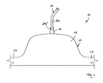
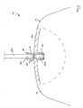
- a hanger 10 has a hanger body 11 made of plastic, which has a central part 12 from which two hanger arms 13 extend to opposite sides.
- a sleeve-shaped collar 14 is formed, which is a bead-like material thickening and has a bore-like receptacle 14 a (FIG. 4) which extends vertically and has a constant circular inner cross section over its height.
- suspension hook 20 at the central part 12 of the hanger body 11 rotatably mounted.
- the hanging hook 20 which consists of metal, has in its lower region in a known manner a vertically extending shank portion 20c on which at a distance from the lower end of the shank portion 20d, an upper cross-sectional widening 20f shown only in Fig. 1 may be formed, for example, by pinching .
- the shank portion 20c has a bearing area 20d, which has a circular cylindrical shape with a smooth, unprofiled lateral surface.
- the nominal outer diameter of the bearing portion 20d is slightly larger than the inner diameter of the receptacle 14a of the collar 14.
- the shaft portion 20c is pushed from above into the receptacle 14a with its radial expansion until the upper cross-sectional widening 20f on the upper side of the Collar 14 is arranged.
- the plastic material of the hanger body 11 or the collar 14 spans radially from the outside on the lateral surface of the bearing portion 20 d, whereby an increased frictional force is generated, which must be overcome for a rotation of the suspension hook 20 within the collar 14.
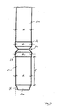
- FIGS. 2 and 3 show a detailed view of the suspension hook 20.
- This is bent in a known manner from a metallic round wire and has in its upper portion a conventionally formed, curved hook portion 20a, formed at the front free end of a spherical head 20b is.
- the vertically downwardly extending shaft portion 20c adjoins.
- the lower end of the vertical shaft portion 20c forms an insertion end 20e, which tapers downwardly at a cone angle ⁇ (see FIG. 3).
- the cone angle ⁇ is preferably less than 30 ° and is in the illustrated embodiment at about 20 °.
- the shank portion 20c has over its entire height a circular cross-section with an initial or nominal outer diameter d. Directly above the conical insertion end 20e, the storage area 20d connects over a length 1 of at least 1 cm.
- the storage area 20d has a smooth, non-profiled lateral surface.
- annular groove 21 is formed in the shank portion 20c, which extends at right angles to the longitudinal extent of the shank portion 20c and has a V-shaped cross section.
- the annular groove 21 is rolled into the shaft portion 20c under material displacement.
- the displaced material is arranged directly above and below the annular groove 21 and converted into a circular-cylindrical annular collar 22 or 23.
- the annular collar 22 and 23 have a circular cross-section, wherein the outer diameter d 1 of the annular collar 22 and 23 is slightly larger than the nominal outer diameter d of the shaft portion 20c and the bearing portion 20d.
- annular groove 21 and the annular collars 22, 23 are arranged on the side of the storage area 20d facing away from the insertion end 20e, the plastic material which is in contact with the lateral surface of the storage area 20d in the assembled state of the suspension hook shown in FIG the annular collar 22 and 23 or the annular groove 21 is not impaired, whereby defined press-fit between the plastic material and the storage area 20d can be achieved.
- the annular groove is in the mounted state of the suspension hook in the region or just above the upper wall 12a of the central part 12 of the hanger body 11th
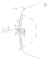
- Fig. 5 shows a development of the embodiment of FIG. 4 and differs from this only in that the collar 14 in its upper, from the middle part 12 of the hanger body 11 upwardly projecting portion of an outer clamping element in the form of a top-mounted clamping cap 15th is surrounded, which preferably consists of steel or plastic and the plastic material of the collar 14 is applied in the upper region with a radially inwardly directed bias and thereby stabilized.
- the hanger body comes into contact directly with the lateral surface of the bearing area 20d.
- a holding part which is inserted into the receptacle 14a of the collar 14, is provided in the form of a bush 16.
- the bushing 16 has projections 16 b on the outside, which engage with the surrounding material of the collar 14 in a form-fitting manner, whereby the bushing 16 is fixed in the collar 14 of the hanger body 11.
- the bushing 16 in turn has a receptacle 16 a formed by a vertical bore into which the lower end of the suspension hook 20 in is pressed manner mentioned.
- the rotational resistance of the suspension hook 20 is essentially determined by the interference fit between the lateral surface of the bearing area 20d of the suspension hook 20 and the material of the bush 16 in abutment therewith.
- the bushing 16 it is possible to manufacture these from a high-grade plastic, for example polycarbonate, while the ironing body 11 can be made from a cheaper plastic, for example a recycled material.
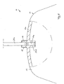
- the hanger body 11 has at least in its middle part 12 a downwardly open C-profile.
- a holding part in the form of a receiving part 17 is provided, which is adapted in its dimensions to the shape of the C-profile of the hanger body 11, so that it is substantially free of play in the interior of the C-profile of the hanger body 11 can be used, as shown in Fig. 9.
- the collar 14 side facing the receiving part 17 has a receptacle formed by a blind hole 17 a.
- the suspension hook To mount the suspension hook it is pressed with its lower insertion end 20e from above through the receptacle 14a of the collar 14 and pushed so far through this that the storage area 20d at least partially on the underside of the collar 14 protrudes from this and into the interior of the central portion 12 of the Hanger body 11 protrudes.
- the receiving part 17 On the protruding lower end of the suspension hook 20, the receiving part 17 is then pressed with its receptacle 17 a, whereby the wall of the receptacle 17 a is widened.
- the assembled state is shown in Fig. 8.
- the axial securing of the suspension hook is essentially determined by the annular groove 21 of the suspension hook 20 lying in the region of the collar 14, while the rotational resistance of the suspension hook is determined substantially by the friction between the bearing portion 20 d and the inner wall of the receptacle 17 a of the receiving part 17, which is held against rotation in the middle part 12 of the hanger body 11.
- the rotational resistance of the suspension hook can be changed and adjusted with relatively little use of material, without the entire bracket body must consist of a high quality and therefore expensive plastic material.
Landscapes
- Holders For Apparel And Elements Relating To Apparel (AREA)
Claims (25)
- Cintre comprenant un corps (11) en matière plastique, dans la partie médiane (12) duquel est fixé, côté partie supérieure, un crochet (20), le crochet (20) à section de tige (20c) verticale inférieure, montée pivotante dans la partie médiane (12) du corps (11) du cintre et présentant au moins dans une zone de logement (20d) une forme cylindrique circulaire de surface extérieure lisse non profilée, la zone de logement (20d) présentant une longueur axiale (1) d'au moins 0,5 cm, plus particulièrement d'au moins 1,0 cm, et la zone de logement (20d) du crochet (20) étant maintenue à ajustage serré sans glissement dans la partie médiane (12) du corps (11) du cintre ou dans un élément de maintien (16; 17) monté sur celui-ci, caractérisé en ce que la zone de logement (20d) est adjacente directement au-dessus d'une extrémité d'introduction (20e) conformée à l'extrémité inférieure de la section de tige (20c).
- Cintre selon la revendication 1, caractérisé en ce qu'au moins une rainure annulaire (21) est conformée dans la section de tige (20c) du crochet (20), au-dessus et/ou au-dessous de la zone de logement (20d).
- Cintre selon la revendication 2, caractérisé en ce que l'on prévoit une seule rainure annulaire (21).
- Cintre selon la revendication 2 ou 3, caractérisé en ce que la rainure annulaire (21) est formée dans la face de la zone de logement (20d) opposée à l'extrémité d'introduction (20e) de la partie terminale du crochet (20).
- Cintre selon l'une quelconque des revendications 2 à 4, caractérisé en ce que la rainure annulaire (21) est située dans la zone ou très légèrement au-dessus d'une paroi supérieure (12a) de la partie médiane (12) du corps (11) du cintre.
- Cintre selon l'une quelconque des revendications 2 à 5, caractérisé en ce qu'immédiatement au-dessus et/ou en-dessous de la rainure annulaire (21) est conformé un rebord (22, 23) annulaire cylindrique circulaire, présentant une surface extérieure lisse, non profilée, et dont le diamètre extérieur (d1) est légèrement supérieur au diamètre extérieur nominal (d) de la section de tige (20c).
- Cintre selon la revendication 6, caractérisé en ce que le diamètre extérieur (d1) du rebord annulaire (22, 23) est supérieur de 0,05 mm à 0,15 mm, plus particulièrement d'environ 0,1 mm, au diamètre extérieur nominal (d) de la section de tige (20c).
- Cintre selon l'une quelconque des revendications 1 à 7, caractérisé en ce que la valeur de l'angle d'entrée (α) de l'extrémité d'introduction (20e) est située dans la plage de 5° à 45°, plus particulièrement dans la plage de 20° à 30°.
- Cintre selon l'une quelconque des revendications 1 à 8, caractérisé en ce qu'un rebord (14) en forme de manchon est formé sur le corps (11) du cintre présentant un logement vertical (14a), dans lequel la zone de logement (20d) du crochet (20) est insérée en générant des forces d'ajustement serré radiales.
- Cintre selon la revendication 9, caractérisé en ce que l'on monte sur une section du rebord (14) en saillie sur la partie supérieure du corps (11) du cintre un élément de tension (15) exerçant sur le rebord (14) une précontrainte dirigée radialement vers l'intérieur.
- Cintre selon la revendication 10, caractérisé en ce que l'élément de tension est un capuchon (15) placé sur le rebord (14).
- Cintre selon l'une quelconque des revendications 1 à 11, caractérisé en ce qu'un logement (16a, 17a) est formé au moins sur certaines sections de l'élément de maintien (16; 17), logement dans lequel la zone de logement (20d) du crochet (20) est insérée en générant des forces d'ajustement serré radiales.
- Cintre selon l'une quelconque des revendications 1 à 12, caractérisé en ce que l'élément de maintien est un coussinet (16) logé dans le rebord (14) et combiné au rebord (14).
- Cintre selon la revendication 12, caractérisé en ce que l'élément de maintien est un élément de réception (17) maintenu à l'intérieur du corps (11) du cintre, qui présente le logement (17a) dans lequel la section de tige (20c) du crochet (20) qui traverse la paroi du cintre est au moins partiellement insérée avec sa zone de logement (20d).
- Cintre selon l'une quelconque des revendications 9 à 14, caractérisé en ce qu'avant l'introduction du crochet (20), le diamètre intérieur du logement (14a, 16a, 17a) est inférieur de 2 à 15%, et plus particulièrement d'environ 10% au diamètre extérieur nominal de la zone de logement (20d) du crochet (20).
- Cintre selon l'une quelconque des revendications 9 à 15, caractérisé en ce que sur la section de tige (20c) du crochet (20) est formé en amont du logement (14a) un élargissement supérieur de diamètre (20f).
- Cintre selon l'une quelconque des revendications 1 à 16, caractérisé en ce que le corps (11) du cintre et/ou l'élément de maintien sont en matière plastique élastique, thermoplastique, plus particulièrement en polystyrène ou en polypropylène ou en polycarbonate.
- Cintre selon l'une quelconque des revendications 1 à 17, caractérisé en ce qu'un revêtement est appliqué au moins sur la zone de logement (20d) de la section de tige (20c).
- Crochet pour un cintre, comprenant une partie supérieure (20a) de crochet et une section inférieure verticale de tige (20c), la section de tige (20c) présentant dans une zone inférieure de logement (20d) une forme cylindrique circulaire de surface extérieure lisse, non profilée, et une rainure annulaire (21) au moins étant formée dans la section de tige (20c) du crochet (20), la zone de logement (20d) présentant une longueur axiale (1) d'au moins 0,5 cm, plus particulièrement d'au moins 1,0 cm, caractérisé en ce que la zone de logement (20d) est directement adjacente au-dessus d'une extrémité d'introduction (20e) formée à l'extrémité inférieure de la section de tige (20c), qui s'effile en cône, et en ce que la rainure annulaire (21) est formée sur la face de la zone de logement (20d) opposée à l'extrémité d'introduction (20e) de la partie terminale de la section de tige (20c).
- Crochet selon la revendication 19, caractérisé en ce que l'on ne prévoit qu'une seule rainure annulaire (21).
- Crochet selon la revendication 19 ou 20, caractérisé en ce qu'immédiatement au-dessus et/ou en-dessous de la rainure annulaire (21) est conformé un rebord (22, 23) annulaire cylindrique circulaire, présentant une surface extérieure lisse, non profilée, et dont le diamètre extérieur (d1) est légèrement supérieur au diamètre extérieur nominal (d) de la section de tige (20c).
- Crochet selon la revendication 21, caractérisé en ce que le diamètre extérieur (d1) du rebord annulaire (22, 23) est supérieur de 0,05 mm à 0,15 mm, plus particulièrement d'environ 0,1 mm, au diamètre extérieur nominal (d) de la section de tige (20c).
- Crochet selon l'une quelconque des revendications 19 à 22, caractérisé en ce que l'extrémité d'introduction (20e) conformée à l'extrémité inférieure de la section de tige (20c) s'effile coniquement selon un angle d'entrée (α) situé dans la plage de 5° à 45°, plus particulièrement dans la plage de 20° à 30°.
- Procédé de fabrication d'un cintre selon l'une quelconque des revendications 1 à 18, dans lequel le corps (11) du cintre est préfabriqué et l'on introduit par pression ou à force le crochet dans un logement (14a; 16a; 17a) du corps (11) du cintre ou un élément de maintien (16, 17) en provoquant l'ouverture radiale de ceux-ci, caractérisé en ce que l'on applique un revêtement au moins sur la zone de logement (20d) de la section de tige (20c) avant l'enfoncement par pression ou à force.
- Procédé selon la revendication 24, caractérisé en ce que le revêtement est appliqué sous forme liquide, plus particulièrement par pulvérisation ou peinture.
Applications Claiming Priority (5)
| Application Number | Priority Date | Filing Date | Title |
|---|---|---|---|
| DE10244276 | 2002-09-23 | ||
| DE2002144276 DE10244276A1 (de) | 2002-09-23 | 2002-09-23 | Kleiderbügel und Verfahren zu seiner Herstellung |
| DE10316596 | 2003-04-11 | ||
| DE2003116596 DE10316596A1 (de) | 2003-04-11 | 2003-04-11 | Kleiderbügel, Verfahren zu seiner Herstellung und Aufhängehaken für einen Kleiderbügel |
| PCT/EP2003/009277 WO2004028316A1 (fr) | 2002-09-23 | 2003-08-21 | Cintre, procede de production correspondant et crochet de suspension approprie |
Publications (2)
| Publication Number | Publication Date |
|---|---|
| EP1555916A1 EP1555916A1 (fr) | 2005-07-27 |
| EP1555916B1 true EP1555916B1 (fr) | 2006-10-11 |
Family
ID=32043956
Family Applications (1)
| Application Number | Title | Priority Date | Filing Date |
|---|---|---|---|
| EP03798117A Expired - Lifetime EP1555916B1 (fr) | 2002-09-23 | 2003-08-21 | Cintre, procede de production correspondant et crochet de suspension approprie |
Country Status (5)
| Country | Link |
|---|---|
| EP (1) | EP1555916B1 (fr) |
| AT (1) | ATE341980T1 (fr) |
| AU (1) | AU2003255471A1 (fr) |
| DE (1) | DE50305380D1 (fr) |
| WO (1) | WO2004028316A1 (fr) |
Cited By (2)
| Publication number | Priority date | Publication date | Assignee | Title |
|---|---|---|---|---|
| DE102008029768A1 (de) | 2008-06-25 | 2009-12-31 | CORONET Kleiderbügel & Logistik GmbH | Kleiderbügel |
| DE202009001779U1 (de) | 2009-02-10 | 2010-07-01 | Cortec Gmbh | Kleiderbügel |
Families Citing this family (3)
| Publication number | Priority date | Publication date | Assignee | Title |
|---|---|---|---|---|
| SI1576909T1 (sl) * | 2004-03-17 | 2006-10-31 | Tfs Global Hanger Man Gmbh | Postopek in naprava za ucvrstitev kljuke v obesalnik za obleke |
| EP1745725A1 (fr) | 2005-07-20 | 2007-01-24 | TFS-Global Hanger Management GmbH | Procédé de protection des cintres pour vêtements ainsi que cintre obtenu par ce procédé |
| GB2536540A (en) * | 2013-11-18 | 2016-09-21 | Mainetti (Uk) Ltd | A hook for a garment hanger |
Family Cites Families (8)
| Publication number | Priority date | Publication date | Assignee | Title |
|---|---|---|---|---|
| GB256380A (en) * | 1925-07-07 | 1926-08-12 | Robert Pollock Boyd | Improvements relating to hangers for coats and like garments |
| CH404914A (de) * | 1962-12-05 | 1965-12-31 | Samuelsson Stig | Vorrichtung an Kleiderbügeln |
| FR2548884B3 (fr) * | 1983-07-12 | 1985-12-20 | Fouassier Jean Pierre | Nouveaux cintres pour vetements, et leur procede de fabrication |
| DE9401642U1 (de) * | 1994-02-01 | 1995-06-01 | Mawa - Metallwarenfabrik Wagner Gmbh, 85276 Pfaffenhofen | Metallkleiderbügel |
| JPH0889386A (ja) * | 1994-09-27 | 1996-04-09 | Hirao Kasei:Kk | 衣類用ハンガーのフック取付構造 |
| JP3177588B2 (ja) * | 1997-03-31 | 2001-06-18 | 株式会社エヌケープロダクツ | 吊掛具におけるフックの高さ調節機構 |
| NL1014216C2 (nl) * | 2000-01-28 | 2001-07-31 | Cleem Beheer B V | Hanginrichting. |
| JP4510223B2 (ja) * | 2000-04-26 | 2010-07-21 | サカエ株式会社 | ハンガーのフック取り付け構造 |
-
2003
- 2003-08-21 EP EP03798117A patent/EP1555916B1/fr not_active Expired - Lifetime
- 2003-08-21 AU AU2003255471A patent/AU2003255471A1/en not_active Abandoned
- 2003-08-21 WO PCT/EP2003/009277 patent/WO2004028316A1/fr not_active Ceased
- 2003-08-21 AT AT03798117T patent/ATE341980T1/de active
- 2003-08-21 DE DE50305380T patent/DE50305380D1/de not_active Expired - Lifetime
Cited By (3)
| Publication number | Priority date | Publication date | Assignee | Title |
|---|---|---|---|---|
| DE102008029768A1 (de) | 2008-06-25 | 2009-12-31 | CORONET Kleiderbügel & Logistik GmbH | Kleiderbügel |
| DE102008029768B4 (de) * | 2008-06-25 | 2018-01-11 | CORONET Kleiderbügel & Logistik GmbH | Kleiderbügel |
| DE202009001779U1 (de) | 2009-02-10 | 2010-07-01 | Cortec Gmbh | Kleiderbügel |
Also Published As
| Publication number | Publication date |
|---|---|
| DE50305380D1 (de) | 2006-11-23 |
| EP1555916A1 (fr) | 2005-07-27 |
| WO2004028316A1 (fr) | 2004-04-08 |
| AU2003255471A1 (en) | 2004-04-19 |
| ATE341980T1 (de) | 2006-11-15 |
Similar Documents
| Publication | Publication Date | Title |
|---|---|---|
| DE69721173T2 (de) | Ankerbolzen | |
| DE69513897T2 (de) | Spreizelement für zahnimplantate | |
| DE2932538A1 (de) | Befestigungseinheit | |
| DE8531404U1 (de) | Drahtspannklemme | |
| DE4224575A1 (de) | Vorrichtung zum verspannenden verbinden von mit abstand zueinanderliegenden bauteilen | |
| CH631521A5 (de) | Verankerungsbuchse. | |
| DE19607972C1 (de) | Vorrichtung zur befestigenden Aufnahme eines stabförmigen Gegenstandes, z. B. eines Pfostens | |
| DE3420804C2 (fr) | ||
| WO1996011343A1 (fr) | Dispositif d'ancrage extensible | |
| EP1555916B1 (fr) | Cintre, procede de production correspondant et crochet de suspension approprie | |
| EP1853135A1 (fr) | Systeme d'etagere | |
| DD153624A5 (de) | Spreizbarer duebel | |
| WO1999002869A1 (fr) | Cheville a expansion | |
| EP2277742A2 (fr) | Dispositif de fixation d'une pièce, par exemple d'une rambarde, sur une carrosserie de véhicule | |
| DE2000971C3 (de) | Spreizdübel, insbesondere für kleine Lasten | |
| DE7016008U (de) | Sicherungsmutter. | |
| DE102008029768B4 (de) | Kleiderbügel | |
| EP0626522B1 (fr) | Cheville à bascule | |
| EP0655300B1 (fr) | Dispositif pour la mise en place d'un tube dans un douille | |
| DE10316596A1 (de) | Kleiderbügel, Verfahren zu seiner Herstellung und Aufhängehaken für einen Kleiderbügel | |
| EP1086639B1 (fr) | Porte-articles, en particulier cintre pour vêtements | |
| DE3426288C2 (de) | Spreizdübel aus Metallblech | |
| DE9015241U1 (de) | Kleiderbügel | |
| EP3962325A1 (fr) | Crochet mural, dispositif de fixation avec le crochet mural et procédé de fixation du crochet mural | |
| DE10244276A1 (de) | Kleiderbügel und Verfahren zu seiner Herstellung |
Legal Events
| Date | Code | Title | Description |
|---|---|---|---|
| PUAI | Public reference made under article 153(3) epc to a published international application that has entered the european phase |
Free format text: ORIGINAL CODE: 0009012 |
|
| 17P | Request for examination filed |
Effective date: 20050406 |
|
| AK | Designated contracting states |
Kind code of ref document: A1 Designated state(s): AT BE BG CH CY CZ DE DK EE ES FI FR GB GR HU IE IT LI LU MC NL PT RO SE SI SK TR |
|
| AX | Request for extension of the european patent |
Extension state: AL LT LV MK |
|
| DAX | Request for extension of the european patent (deleted) | ||
| GRAP | Despatch of communication of intention to grant a patent |
Free format text: ORIGINAL CODE: EPIDOSNIGR1 |
|
| RAP1 | Party data changed (applicant data changed or rights of an application transferred) |
Owner name: CORONET KLEIDERBUEGEL & LOGISTIK GMBH |
|
| GRAS | Grant fee paid |
Free format text: ORIGINAL CODE: EPIDOSNIGR3 |
|
| GRAA | (expected) grant |
Free format text: ORIGINAL CODE: 0009210 |
|
| AK | Designated contracting states |
Kind code of ref document: B1 Designated state(s): AT BE BG CH CY CZ DE DK EE ES FI FR GB GR HU IE IT LI LU MC NL PT RO SE SI SK TR |
|
| PG25 | Lapsed in a contracting state [announced via postgrant information from national office to epo] |
Ref country code: FI Free format text: LAPSE BECAUSE OF FAILURE TO SUBMIT A TRANSLATION OF THE DESCRIPTION OR TO PAY THE FEE WITHIN THE PRESCRIBED TIME-LIMIT Effective date: 20061011 Ref country code: IT Free format text: LAPSE BECAUSE OF FAILURE TO SUBMIT A TRANSLATION OF THE DESCRIPTION OR TO PAY THE FEE WITHIN THE PRESCRIBED TIME-LIMIT;WARNING: LAPSES OF ITALIAN PATENTS WITH EFFECTIVE DATE BEFORE 2007 MAY HAVE OCCURRED AT ANY TIME BEFORE 2007. THE CORRECT EFFECTIVE DATE MAY BE DIFFERENT FROM THE ONE RECORDED. Effective date: 20061011 Ref country code: SI Free format text: LAPSE BECAUSE OF FAILURE TO SUBMIT A TRANSLATION OF THE DESCRIPTION OR TO PAY THE FEE WITHIN THE PRESCRIBED TIME-LIMIT Effective date: 20061011 Ref country code: IE Free format text: LAPSE BECAUSE OF FAILURE TO SUBMIT A TRANSLATION OF THE DESCRIPTION OR TO PAY THE FEE WITHIN THE PRESCRIBED TIME-LIMIT Effective date: 20061011 Ref country code: RO Free format text: LAPSE BECAUSE OF FAILURE TO SUBMIT A TRANSLATION OF THE DESCRIPTION OR TO PAY THE FEE WITHIN THE PRESCRIBED TIME-LIMIT Effective date: 20061011 Ref country code: CZ Free format text: LAPSE BECAUSE OF FAILURE TO SUBMIT A TRANSLATION OF THE DESCRIPTION OR TO PAY THE FEE WITHIN THE PRESCRIBED TIME-LIMIT Effective date: 20061011 Ref country code: SK Free format text: LAPSE BECAUSE OF FAILURE TO SUBMIT A TRANSLATION OF THE DESCRIPTION OR TO PAY THE FEE WITHIN THE PRESCRIBED TIME-LIMIT Effective date: 20061011 |
|
| REG | Reference to a national code |
Ref country code: GB Ref legal event code: FG4D Free format text: NOT ENGLISH |
|
| REG | Reference to a national code |
Ref country code: CH Ref legal event code: EP |
|
| REG | Reference to a national code |
Ref country code: IE Ref legal event code: FG4D Free format text: LANGUAGE OF EP DOCUMENT: GERMAN |
|
| REF | Corresponds to: |
Ref document number: 50305380 Country of ref document: DE Date of ref document: 20061123 Kind code of ref document: P |
|
| REG | Reference to a national code |
Ref country code: CH Ref legal event code: NV Representative=s name: TROESCH SCHEIDEGGER WERNER AG |
|
| PG25 | Lapsed in a contracting state [announced via postgrant information from national office to epo] |
Ref country code: SE Free format text: LAPSE BECAUSE OF FAILURE TO SUBMIT A TRANSLATION OF THE DESCRIPTION OR TO PAY THE FEE WITHIN THE PRESCRIBED TIME-LIMIT Effective date: 20070111 Ref country code: BG Free format text: LAPSE BECAUSE OF FAILURE TO SUBMIT A TRANSLATION OF THE DESCRIPTION OR TO PAY THE FEE WITHIN THE PRESCRIBED TIME-LIMIT Effective date: 20070111 Ref country code: DK Free format text: LAPSE BECAUSE OF FAILURE TO SUBMIT A TRANSLATION OF THE DESCRIPTION OR TO PAY THE FEE WITHIN THE PRESCRIBED TIME-LIMIT Effective date: 20070111 |
|
| PG25 | Lapsed in a contracting state [announced via postgrant information from national office to epo] |
Ref country code: ES Free format text: LAPSE BECAUSE OF FAILURE TO SUBMIT A TRANSLATION OF THE DESCRIPTION OR TO PAY THE FEE WITHIN THE PRESCRIBED TIME-LIMIT Effective date: 20070122 |
|
| PG25 | Lapsed in a contracting state [announced via postgrant information from national office to epo] |
Ref country code: PT Free format text: LAPSE BECAUSE OF FAILURE TO SUBMIT A TRANSLATION OF THE DESCRIPTION OR TO PAY THE FEE WITHIN THE PRESCRIBED TIME-LIMIT Effective date: 20070319 |
|
| ET | Fr: translation filed | ||
| GBV | Gb: ep patent (uk) treated as always having been void in accordance with gb section 77(7)/1977 [no translation filed] |
Effective date: 20061011 |
|
| REG | Reference to a national code |
Ref country code: IE Ref legal event code: FD4D |
|
| PLBE | No opposition filed within time limit |
Free format text: ORIGINAL CODE: 0009261 |
|
| STAA | Information on the status of an ep patent application or granted ep patent |
Free format text: STATUS: NO OPPOSITION FILED WITHIN TIME LIMIT |
|
| 26N | No opposition filed |
Effective date: 20070712 |
|
| PG25 | Lapsed in a contracting state [announced via postgrant information from national office to epo] |
Ref country code: GB Free format text: LAPSE BECAUSE OF FAILURE TO SUBMIT A TRANSLATION OF THE DESCRIPTION OR TO PAY THE FEE WITHIN THE PRESCRIBED TIME-LIMIT Effective date: 20061011 |
|
| BERE | Be: lapsed |
Owner name: CORONET KLEIDERBUGEL & LOGISTIK G.M.B.H. Effective date: 20070831 |
|
| PG25 | Lapsed in a contracting state [announced via postgrant information from national office to epo] |
Ref country code: MC Free format text: LAPSE BECAUSE OF NON-PAYMENT OF DUE FEES Effective date: 20070831 Ref country code: GR Free format text: LAPSE BECAUSE OF FAILURE TO SUBMIT A TRANSLATION OF THE DESCRIPTION OR TO PAY THE FEE WITHIN THE PRESCRIBED TIME-LIMIT Effective date: 20070112 |
|
| PG25 | Lapsed in a contracting state [announced via postgrant information from national office to epo] |
Ref country code: BE Free format text: LAPSE BECAUSE OF NON-PAYMENT OF DUE FEES Effective date: 20070831 |
|
| PG25 | Lapsed in a contracting state [announced via postgrant information from national office to epo] |
Ref country code: EE Free format text: LAPSE BECAUSE OF FAILURE TO SUBMIT A TRANSLATION OF THE DESCRIPTION OR TO PAY THE FEE WITHIN THE PRESCRIBED TIME-LIMIT Effective date: 20061011 |
|
| PG25 | Lapsed in a contracting state [announced via postgrant information from national office to epo] |
Ref country code: CY Free format text: LAPSE BECAUSE OF FAILURE TO SUBMIT A TRANSLATION OF THE DESCRIPTION OR TO PAY THE FEE WITHIN THE PRESCRIBED TIME-LIMIT Effective date: 20061011 Ref country code: LU Free format text: LAPSE BECAUSE OF NON-PAYMENT OF DUE FEES Effective date: 20070821 |
|
| PG25 | Lapsed in a contracting state [announced via postgrant information from national office to epo] |
Ref country code: TR Free format text: LAPSE BECAUSE OF FAILURE TO SUBMIT A TRANSLATION OF THE DESCRIPTION OR TO PAY THE FEE WITHIN THE PRESCRIBED TIME-LIMIT Effective date: 20061011 Ref country code: HU Free format text: LAPSE BECAUSE OF FAILURE TO SUBMIT A TRANSLATION OF THE DESCRIPTION OR TO PAY THE FEE WITHIN THE PRESCRIBED TIME-LIMIT Effective date: 20070412 |
|
| REG | Reference to a national code |
Ref country code: FR Ref legal event code: PLFP Year of fee payment: 14 |
|
| REG | Reference to a national code |
Ref country code: FR Ref legal event code: PLFP Year of fee payment: 15 |
|
| REG | Reference to a national code |
Ref country code: FR Ref legal event code: PLFP Year of fee payment: 16 |
|
| PGFP | Annual fee paid to national office [announced via postgrant information from national office to epo] |
Ref country code: FR Payment date: 20180828 Year of fee payment: 16 Ref country code: NL Payment date: 20180822 Year of fee payment: 16 Ref country code: DE Payment date: 20180816 Year of fee payment: 16 |
|
| PGFP | Annual fee paid to national office [announced via postgrant information from national office to epo] |
Ref country code: CH Payment date: 20180827 Year of fee payment: 16 Ref country code: AT Payment date: 20180821 Year of fee payment: 16 |
|
| REG | Reference to a national code |
Ref country code: DE Ref legal event code: R119 Ref document number: 50305380 Country of ref document: DE |
|
| REG | Reference to a national code |
Ref country code: NL Ref legal event code: MM Effective date: 20190901 |
|
| REG | Reference to a national code |
Ref country code: AT Ref legal event code: MM01 Ref document number: 341980 Country of ref document: AT Kind code of ref document: T Effective date: 20190821 |
|
| PG25 | Lapsed in a contracting state [announced via postgrant information from national office to epo] |
Ref country code: AT Free format text: LAPSE BECAUSE OF NON-PAYMENT OF DUE FEES Effective date: 20190821 |
|
| PG25 | Lapsed in a contracting state [announced via postgrant information from national office to epo] |
Ref country code: LI Free format text: LAPSE BECAUSE OF NON-PAYMENT OF DUE FEES Effective date: 20190831 Ref country code: CH Free format text: LAPSE BECAUSE OF NON-PAYMENT OF DUE FEES Effective date: 20190831 |
|
| PG25 | Lapsed in a contracting state [announced via postgrant information from national office to epo] |
Ref country code: FR Free format text: LAPSE BECAUSE OF NON-PAYMENT OF DUE FEES Effective date: 20190831 Ref country code: DE Free format text: LAPSE BECAUSE OF NON-PAYMENT OF DUE FEES Effective date: 20200303 Ref country code: NL Free format text: LAPSE BECAUSE OF NON-PAYMENT OF DUE FEES Effective date: 20190901 |