EP1555684A1 - Mehrfunktionschalter mit Anzeigevorrichtung - Google Patents
Mehrfunktionschalter mit Anzeigevorrichtung Download PDFInfo
- Publication number
- EP1555684A1 EP1555684A1 EP05001016A EP05001016A EP1555684A1 EP 1555684 A1 EP1555684 A1 EP 1555684A1 EP 05001016 A EP05001016 A EP 05001016A EP 05001016 A EP05001016 A EP 05001016A EP 1555684 A1 EP1555684 A1 EP 1555684A1
- Authority
- EP
- European Patent Office
- Prior art keywords
- indicator
- dial knob
- support
- multifunctional switch
- switch
- Prior art date
- Legal status (The legal status is an assumption and is not a legal conclusion. Google has not performed a legal analysis and makes no representation as to the accuracy of the status listed.)
- Withdrawn
Links
- 239000000758 substrate Substances 0.000 description 7
- 230000005540 biological transmission Effects 0.000 description 6
- 238000003780 insertion Methods 0.000 description 2
- 230000037431 insertion Effects 0.000 description 2
- 239000000853 adhesive Substances 0.000 description 1
- 230000001070 adhesive effect Effects 0.000 description 1
- 238000006073 displacement reaction Methods 0.000 description 1
- 239000004973 liquid crystal related substance Substances 0.000 description 1
- 238000012986 modification Methods 0.000 description 1
- 230000004048 modification Effects 0.000 description 1
Images



Classifications
-
- H—ELECTRICITY
- H01—ELECTRIC ELEMENTS
- H01H—ELECTRIC SWITCHES; RELAYS; SELECTORS; EMERGENCY PROTECTIVE DEVICES
- H01H9/00—Details of switching devices, not covered by groups H01H1/00 - H01H7/00
- H01H9/18—Distinguishing marks on switches, e.g. for indicating switch location in the dark; Adaptation of switches to receive distinguishing marks
- H01H9/181—Distinguishing marks on switches, e.g. for indicating switch location in the dark; Adaptation of switches to receive distinguishing marks using a programmable display, e.g. LED or LCD
-
- H—ELECTRICITY
- H01—ELECTRIC ELEMENTS
- H01H—ELECTRIC SWITCHES; RELAYS; SELECTORS; EMERGENCY PROTECTIVE DEVICES
- H01H25/00—Switches with compound movement of handle or other operating part
- H01H25/06—Operating part movable both angularly and rectilinearly, the rectilinear movement being along the axis of angular movement
-
- H—ELECTRICITY
- H01—ELECTRIC ELEMENTS
- H01H—ELECTRIC SWITCHES; RELAYS; SELECTORS; EMERGENCY PROTECTIVE DEVICES
- H01H2300/00—Orthogonal indexing scheme relating to electric switches, relays, selectors or emergency protective devices covered by H01H
- H01H2300/038—Preselection, i.e. the output of a switch depends on a particular preselection, e.g. a particular position of another switch
Definitions
- the present invention relates to a multifunctional switch with an Indicator, in which a plurality of functions can be selected by a combination of rotation of a dial knob and an operation of switches.
- Japanese Patent Application Laid-open No. 2003-054290 discloses a related art of a multifunctional switch with an indicator.
- the multifunctional switch is provided with a dial knob and a rotary encoder linked with a plurality of switches. Functions can be selected by rotating the dial knob.
- the dial knob is provided with a translucent window at a center thereof so that an operator can see an indicator (LCD) installed therein.
- LCD indicator
- the translucent window moves with the dial knob in a case where the dial knob is rotated and hence a relative distance between the translucent window and the indicator is necessarily changeable. Therefore it is necessary to give enough distance therebetween for operation of the dial knob.
- the present invention is intended for providing a multifunctional switch with an indicator, in which a distance between the translucent window and the indicator can be unchangeable and set short so as to give clear view of the indicator.
- a multifunctional switch is provided with a dial knob capable of being pushed in an axial direction and rotated; a window formed at a center of the dial knob; an indicator configured to indicate a selected function; an indicator support configured to support the indicator and disposed at a rear of the dial knob, the dial knob being rotatably fitted on the indicator support and movable with the indicator support in the axial direction; and means for anti-rotation of the indicator support.
- the multifunctional switch is further provided with a first tact switch including repulsive means so as to support and urge the indicator support toward the dial knob.
- the multifunctional switch is further provided with one or more second tact switches disposed around the dial knob and an indicia plate indicating the functions of the second tact switches, the indicia plate being interposed between the indicator and the dial knob.
- the means for anti-rotation of the indicator support is a combination of one or more rails and one or more slots.
- a multifunctional switch 1 is applied to an automobile and preferably installed on an instrument panel of the automobile.
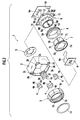
- the multifunctional switch 1 is provided with a casing 2, which has a rectangular cross section, a dial knob 3 disposed in front of the casing 2 and push buttons 4 respectively disposed on four corners of the casing 2 as shown in Fig. 1.
- the multifunctional switch 1 is installed in the automobile so that the front faces rearward with respect to a direction where the automobile moves.
- the dial knob 3 is capable of being rotated and pushed with respect to the casing 2. Switches can be selected by a combination of such rotation and pushing operations.
- the push buttons 4 are also capable of being pushed with respect to the casing 2.
- the multifunctional switch 1 is further provided with an indicia plate 5, on which black ink and some signs are printed, a liquid crystal display (LCD) plate 6 for an indicator, an indicator support 7, a transmission ring 8, a rotary encoder 9 and a back substrate 10 housed in the casing 2 as shown in Fig. 2.
- LCD liquid crystal display
- the dial knob 3 is providedwith a short cylindrical portion 3a and a tapered portion in front of the cylindrical portion 3a.
- a window 3b is coaxially formed in front of the tapered portion and at a center of the dial knob 3.
- a lens 11 is engaged in the window 3b.
- a serration 3c is formed on an inner periphery of the cylindrical portion 3a so as to engage with an outer periphery of the transmission ring 8.
- the casing 3 is provided with fitting portions 2a, with which the outer surface of the cylindrical portion 3a of the dial knob 3 rotatably fits.
- the fitting portions 2a constitute a hypothetical cylindrical surface but four portions thereof, correspondingly to four corners of the casing 3, are cut-off so as to form cut-off sections 2b.
- Four corners of the casing 3 are respectively provided with insertion portions 2c, to which the push buttons 4 are respectively movably inserted.
- Each of the push buttons 4 is provided with a button top 4a, which fits any of the cut-off sections 2b, and a proximal portion 4b, which is movably inserted into any of the insertion portions 2c.
- the operator utilizes the button top 4a for operation by his or her finger.
- the indicator support 7 is disposed at a rear of the dial knob 3.
- the indicator support 7 is provided with a disk-like flange 7a, with which the dial knob 3 rotatably fits, and a cylindrical portion 7b projecting rearward (forward with respect to the direction where the automobile moves).
- the cylindrical portion 7b has a plurality of rails 7c (four rails are drawn in Fig. 2) running fore and aft on an outer circumference thereof.
- the indicator support 7 is further provided with a rectangular recess 7d, in which the LCD plate 6 fits.
- the LCD plate 6 has a rectangular shape so as to fit with the rectangular recess 7d.
- the transmission ring 8 has a ring-like shape so as to fit in the interior of the dial knob 3 and has a serration 8a for engaging with the serration 3c of the dial knob 3.
- the serrations 3c and 8a are engaged with each other so that rotation of the dial knob 3 is transmitted to the transmission ring 8.
- the dial knob 3 is prevented from dropping off from the transmission ring 8 by means of anti-droppingmeans (not shown).
- the rotary encoder 9 is provided with an inner fixed cylinder 9a and an outer rotary cylinder 9b.
- the inner fixed cylinder 9a is fixed with a main substrate 9c which is formed in a rectangular plate shape fitting with the interior of the casing 2.
- the outer rotary cylinder 9b is rotatably fitted with the inner fixed cylinder 9a and further prevented from axially displacing with respect to the inner fixed cylinder 9a.
- the rotary encoder 9 is configured to detect a rotation angle of the outer rotary cylinder 9b with respect to the inner fixed cylinder 9a so as to select switches.
- the inner fixed cylinder 9a has a plurality of slots 9d (four slots drawn in Fig . 2) on an inner surface thereof.
- the rails 7c of the indicator support 7 slidably engage with the slots 9d so as to allow axial displacement of the dial knob 3 via the indicator support 7.
- the combination of the rails 7c and the slots 9d, as well, functions as means for anti-rotation of the LCD plate 6.
- the main substrate 9c is provided with a first tact switch 12 and a plurality of second tact switches 13 in a manner that the first tact switch 12 faces to an end of the indicator support 7 and the second tact switches 13 respectively face to ends of the push buttons 4.
- the tact switches 12 and 13 respectively have return springs built therein. In a state that multifunctional switch 1 is integrated, the tact switches 12 and 13 touch the ends of the indicator support 7 and the push buttons 4 and repulsive forces of the return springs act on the indicator support 7 and the push buttons 4 via the tact switches 12 and 13.
- the main substrate 9c 1s further provided with a back-light 14, to which a LED is applied, for illuminating the LCD plate 6.
- the back-light 14 is disposed at a center of the rotary encoder 9.
- the back substrate 10 is fitted in and closes a substantially rearmost (foremost with respect to the direction where the automobile moves) end of the casing 2.
- the back substrate 10 is provided with a support projection 15 projecting from a rear surface thereof as shown in Fig. 3.
- a wiring harness 6a linking with the LCD plate 6 such as FPC and a wiring harness 14a linking with the back-light 14 are led rearward out of the back substrate 10.
- the dial knob 3 fits with the disk-like flange 7a of the indicator support 7 with the LCD plate 6 put therebetween.
- the indicator support 7 is interposed between the dial knob 3 and the first tact switch 12 and hence urged toward the dial knob 3 by the repulsive force of the first tact switch 12.
- the indicia plate 5 is interposed between the LCD plate 6 and the dial knob 3 and covers the periphery of the LCD plate 6.
- the indicia plate 5 is adhered to the LCD plate 6 by an adhesive for anti-rotation.
- the indicia plate 5 indicates signs of respective functions of the push buttons 4 disposed around the dial knob 3. For example, as shown in Fig. 4, the indicia plate 5 indicates "AUTO" at a position P1, "OFF” at a position P2, a pictorial symbol of a defroster at a position P3 and a pictorial symbol of air recirculation at a position P4 with a white ink on a black background.
- the indicia plate 5 further indicates black triangles for pointing the respective push buttons 4.
- the rotary encoder 9 reads the rotation angle and lets the LCD plate 6 indicate the function corresponding to the rotation angle.
- the first tact switch 12 can be operated by pushing the dial knob 3 via the indicator support 7 and the rotary encoder 9 can be operated by rotating the dial knob 3 via the transmission ring 8.
- the functions of the switches can be selected by the rotary encoder 9 by means of rotating the dial knob 3.
- a relative distance between the dial knob 3 and the LCD plate 6 is kept constant since the LCD plate 6 is supported between the dial knob 3 and the indicator support 7. Therefore the LCD plate 6 can be disposed close to the window 3b of the dial knob 3 and hence a relatively wide area of the LCD plate 6 is present to view through the window 3b. The operator can see the indication of the LCD plate 6 clearly.
- the constancy of the relative distance provides a freedom of selection of the lens 11. Since the relative distance is constant, any lens having a short focal length can be applied to the lens 11. Thereby the indication of the LCD plate 6 can be more clearly magnified.
- the LCD plate 6 is kept in an upright position since the indicator support 7 is anti-rotated with respect to the rotary encoder 9 by means of the combination of the rails 7c and the slots 9d and hence the operator can constantly see the indication in an upright state.
- the LCD indicator 6 can be disposed further close to the window 3b of the dial knob 3 since the LCD indicator 6 is urged by the repulsive force of the first tact switch 12.
- An operation feeling of the dial knob 3 can be controlled by properly controlling the coefficient of friction of the indicia plate 5.
Landscapes
- Switches With Compound Operations (AREA)
- Instrument Panels (AREA)
Applications Claiming Priority (2)
| Application Number | Priority Date | Filing Date | Title |
|---|---|---|---|
| JP2004010251A JP2005203297A (ja) | 2004-01-19 | 2004-01-19 | 表示式多機能スイッチ |
| JP2004010251 | 2004-01-19 |
Publications (1)
| Publication Number | Publication Date |
|---|---|
| EP1555684A1 true EP1555684A1 (de) | 2005-07-20 |
Family
ID=34616933
Family Applications (1)
| Application Number | Title | Priority Date | Filing Date |
|---|---|---|---|
| EP05001016A Withdrawn EP1555684A1 (de) | 2004-01-19 | 2005-01-19 | Mehrfunktionschalter mit Anzeigevorrichtung |
Country Status (3)
| Country | Link |
|---|---|
| US (1) | US7141748B2 (de) |
| EP (1) | EP1555684A1 (de) |
| JP (1) | JP2005203297A (de) |
Cited By (11)
| Publication number | Priority date | Publication date | Assignee | Title |
|---|---|---|---|---|
| WO2007028732A1 (de) * | 2005-09-09 | 2007-03-15 | Siemens Vdo Automotive Ag | Anzeige mit einem elektrooptischen display |
| DE102006011276B3 (de) * | 2006-03-10 | 2007-09-06 | Silcos Gmbh | Mehrfachschalter |
| WO2011113714A1 (fr) * | 2010-03-19 | 2011-09-22 | Delphi Technologies, Inc. | Agencement pour le montage d'un afficheur électronique |
| EP2490240A1 (de) | 2011-02-15 | 2012-08-22 | Delphi Technologies, Inc. | Drehschalter mit Drückfunktion |
| GB2494420A (en) * | 2011-09-07 | 2013-03-13 | Jaguar Cars | Rotary control knob with display |
| WO2014161841A3 (de) * | 2013-04-05 | 2015-01-15 | Valeo Schalter Und Sensoren Gmbh | Bedienvorrichtung für ein kraftfahrzeug und lenkrad mit einer bedienvorrichtung |
| EP3168357A1 (de) * | 2015-11-16 | 2017-05-17 | Electrolux Appliances Aktiebolag | Wäschebehandlungsvorrichtung |
| EP3503146A1 (de) * | 2017-12-20 | 2019-06-26 | Bartscher GmbH | Haushaltsgerät mit bedienelement und anzeige |
| US10358761B2 (en) | 2015-11-16 | 2019-07-23 | Electrolux Appliances Aktiebolag | Household appliance with a rotational user interface element |
| US10503286B2 (en) | 2015-11-16 | 2019-12-10 | Electrolux Appliances Aktiebolag | Household appliance with a user interface element |
| WO2020182224A1 (zh) * | 2019-03-14 | 2020-09-17 | 广东美的厨房电器制造有限公司 | 交互组件和家用电器 |
Families Citing this family (56)
| Publication number | Priority date | Publication date | Assignee | Title |
|---|---|---|---|---|
| ATE448108T1 (de) * | 2003-10-20 | 2009-11-15 | Volkswagen Ag | Drehknopf für ein kraftfahrzeug |
| US7339128B2 (en) * | 2004-12-29 | 2008-03-04 | George Yen | All-color light control switch |
| TWI273618B (en) * | 2005-05-24 | 2007-02-11 | Behavior Tech Computer Corp | Framework suited for a slim key and the slim key containing the framework |
| US7342186B2 (en) * | 2006-07-11 | 2008-03-11 | Delphi Technologies, Inc. | Knob force transfer module |
| US7784704B2 (en) | 2007-02-09 | 2010-08-31 | Harter Robert J | Self-programmable thermostat |
| JP4930719B2 (ja) * | 2007-09-20 | 2012-05-16 | 株式会社デンソー | 車載用電子機器操作装置 |
| JP5323364B2 (ja) * | 2008-02-15 | 2013-10-23 | 株式会社マキタ | 電動工具 |
| JP2010048106A (ja) * | 2008-08-19 | 2010-03-04 | Tokai Rika Co Ltd | 電源状態切換装置 |
| US8727611B2 (en) | 2010-11-19 | 2014-05-20 | Nest Labs, Inc. | System and method for integrating sensors in thermostats |
| US9104211B2 (en) | 2010-11-19 | 2015-08-11 | Google Inc. | Temperature controller with model-based time to target calculation and display |
| US8843239B2 (en) | 2010-11-19 | 2014-09-23 | Nest Labs, Inc. | Methods, systems, and related architectures for managing network connected thermostats |
| US8918219B2 (en) | 2010-11-19 | 2014-12-23 | Google Inc. | User friendly interface for control unit |
| US9552002B2 (en) | 2010-11-19 | 2017-01-24 | Google Inc. | Graphical user interface for setpoint creation and modification |
| US9459018B2 (en) | 2010-11-19 | 2016-10-04 | Google Inc. | Systems and methods for energy-efficient control of an energy-consuming system |
| US10346275B2 (en) | 2010-11-19 | 2019-07-09 | Google Llc | Attributing causation for energy usage and setpoint changes with a network-connected thermostat |
| US8850348B2 (en) | 2010-12-31 | 2014-09-30 | Google Inc. | Dynamic device-associated feedback indicative of responsible device usage |
| US9256230B2 (en) | 2010-11-19 | 2016-02-09 | Google Inc. | HVAC schedule establishment in an intelligent, network-connected thermostat |
| US8195313B1 (en) | 2010-11-19 | 2012-06-05 | Nest Labs, Inc. | Thermostat user interface |
| US9453655B2 (en) | 2011-10-07 | 2016-09-27 | Google Inc. | Methods and graphical user interfaces for reporting performance information for an HVAC system controlled by a self-programming network-connected thermostat |
| US10241527B2 (en) | 2010-11-19 | 2019-03-26 | Google Llc | Thermostat graphical user interface |
| US9075419B2 (en) | 2010-11-19 | 2015-07-07 | Google Inc. | Systems and methods for a graphical user interface of a controller for an energy-consuming system having spatially related discrete display elements |
| US11334034B2 (en) | 2010-11-19 | 2022-05-17 | Google Llc | Energy efficiency promoting schedule learning algorithms for intelligent thermostat |
| US9092039B2 (en) | 2010-11-19 | 2015-07-28 | Google Inc. | HVAC controller with user-friendly installation features with wire insertion detection |
| JP5635936B2 (ja) * | 2011-03-31 | 2014-12-03 | 株式会社東海理化電機製作所 | 操作装置 |
| US9115908B2 (en) | 2011-07-27 | 2015-08-25 | Honeywell International Inc. | Systems and methods for managing a programmable thermostat |
| KR20130027255A (ko) * | 2011-09-07 | 2013-03-15 | 삼성전자주식회사 | 키 조립체 및 이를 구비한 회전식 입력 장치 |
| US8893032B2 (en) | 2012-03-29 | 2014-11-18 | Google Inc. | User interfaces for HVAC schedule display and modification on smartphone or other space-limited touchscreen device |
| US9222693B2 (en) | 2013-04-26 | 2015-12-29 | Google Inc. | Touchscreen device user interface for remote control of a thermostat |
| JP2014534405A (ja) | 2011-10-21 | 2014-12-18 | ネスト・ラブズ・インコーポレイテッド | ユーザフレンドリーな、ネットワーク接続された学習サーモスタットならびに関連するシステムおよび方法 |
| CN106440187A (zh) | 2011-10-21 | 2017-02-22 | 谷歌公司 | 用于智能恒温器的能效促进时间表学习算法 |
| CN106444471B (zh) | 2011-10-21 | 2019-04-16 | 谷歌有限责任公司 | 智能控制器和用于自动学习控制时间表的方法 |
| CN106288191B (zh) | 2012-03-29 | 2020-08-25 | 谷歌有限责任公司 | 处理并报告用于网络连接恒温器控制的hvac系统的使用信息 |
| US10054964B2 (en) * | 2012-05-07 | 2018-08-21 | Google Llc | Building control unit method and controls |
| US8708242B2 (en) | 2012-09-21 | 2014-04-29 | Nest Labs, Inc. | Thermostat system with software-repurposable wiring terminals adaptable for HVAC systems of different ranges of complexity |
| US9607787B2 (en) | 2012-09-21 | 2017-03-28 | Google Inc. | Tactile feedback button for a hazard detector and fabrication method thereof |
| US9046414B2 (en) | 2012-09-21 | 2015-06-02 | Google Inc. | Selectable lens button for a hazard detector and method therefor |
| ITMO20120235A1 (it) * | 2012-09-27 | 2014-03-28 | Datalogic IP Tech Srl | Sensore optoelettronico per la rilevazione di una o più caratteristiche di un oggetto |
| DE102012110633A1 (de) * | 2012-11-07 | 2014-05-08 | Shanpu Co., Ltd. | Mehrfunktionsschalter mit Anzeige |
| JP2014103987A (ja) * | 2012-11-22 | 2014-06-09 | Omron Corp | 操作ユニット |
| DE102013215104A1 (de) * | 2013-08-01 | 2015-02-05 | Ford Global Technologies, Llc | Lichtschaltereinheit, sowie Verfahren zur Steuerung der Außenbeleuchtung eines Kraftfahrzeuges |
| JP6349224B2 (ja) * | 2014-10-07 | 2018-06-27 | ジェコー株式会社 | 操作装置 |
| JP2016087472A (ja) * | 2014-11-04 | 2016-05-23 | 株式会社大一商会 | 遊技機 |
| US9702582B2 (en) | 2015-10-12 | 2017-07-11 | Ikorongo Technology, LLC | Connected thermostat for controlling a climate system based on a desired usage profile in comparison to other connected thermostats controlling other climate systems |
| JP6607573B2 (ja) * | 2016-08-10 | 2019-11-20 | オムロンオートモーティブエレクトロニクス株式会社 | スイッチ装置 |
| US10649556B2 (en) * | 2016-12-09 | 2020-05-12 | Dongguan Chen Da Appliance Co. Ltd. | Control knob for controlling operation of a machine |
| DE102017211383A1 (de) * | 2017-07-04 | 2019-01-10 | Bayerische Motoren Werke Aktiengesellschaft | Lenkrad-Bedieneinrichtung sowie Kraftfahrzeug mit einer Lenkrad-Bedieneinrichtung |
| CN207529869U (zh) * | 2017-12-18 | 2018-06-22 | 东莞辰达电器有限公司 | 一种带显示功能的旋钮 |
| US10777370B1 (en) * | 2018-01-03 | 2020-09-15 | David Worsham | Pushbutton switch with light-transmitting indicia on the pushbutton |
| CN110631167B (zh) * | 2019-09-23 | 2024-03-01 | 珠海格力电器股份有限公司 | 控制器、电控设备及控制器的控制方法 |
| TWI701692B (zh) * | 2019-11-22 | 2020-08-11 | 褚錦雄 | 多功能按壓式旋鈕 |
| CN110989764A (zh) * | 2019-12-11 | 2020-04-10 | 广东美的厨房电器制造有限公司 | 旋钮、面板组件及家用电器 |
| CN110953730A (zh) * | 2019-12-19 | 2020-04-03 | 广东威博电器有限公司 | 一种具有新颖控温结构的电热水器 |
| WO2021132772A1 (ko) * | 2019-12-27 | 2021-07-01 | 주식회사 휴롬 | 조그 다이얼 장치 |
| US11113933B1 (en) * | 2020-02-28 | 2021-09-07 | Therm-Omega-Tech, Inc. | Visual indication system for feedback controller |
| KR102733274B1 (ko) * | 2022-12-06 | 2024-11-25 | 현대모비스 주식회사 | 디스플레이 표시형 제어기기 |
| CN220958819U (zh) * | 2023-10-19 | 2024-05-14 | 深圳市普瑞美泰环保科技有限公司 | 空气净化器 |
Citations (3)
| Publication number | Priority date | Publication date | Assignee | Title |
|---|---|---|---|---|
| FR2828761A1 (fr) * | 2001-08-14 | 2003-02-21 | Lcd Solution | Commutateur programmable a affichage actionnable par pression et/ou par rotation |
| JP2003054290A (ja) | 2001-08-20 | 2003-02-26 | Denso Corp | 車両用スイッチ装置 |
| JP2004010251A (ja) | 2002-06-06 | 2004-01-15 | Canon Inc | 画像形成方法及び装置 |
Family Cites Families (13)
| Publication number | Priority date | Publication date | Assignee | Title |
|---|---|---|---|---|
| GB9111811D0 (en) * | 1991-06-01 | 1991-07-24 | Ford New Holland Limited | Power take-off devices |
| US5916288A (en) * | 1996-09-03 | 1999-06-29 | Ut Automotive Dearborn, Inc. | Multi-functional control switch arrangement |
| US6274835B1 (en) * | 1999-11-15 | 2001-08-14 | Siemens Energy & Automation | Selector switch operator |
| US6340800B1 (en) * | 2000-05-27 | 2002-01-22 | International Business Machines Corporation | Multiplexing control device and method for electronic systems |
| US6968510B2 (en) * | 2001-02-05 | 2005-11-22 | Alpine Electronics, Inc. | Function executing apparatus and menu item displaying method therefor |
| US6987233B2 (en) * | 2001-03-12 | 2006-01-17 | Magtech Usa, Inc. | Push-button type electrical switch having secondary conductive pathway to ground |
| JP3592258B2 (ja) * | 2001-06-13 | 2004-11-24 | 株式会社スタッフ | スプリングによって付勢されるブラシを用いた綿菓子製造装置 |
| SE520222C2 (sv) * | 2001-10-15 | 2003-06-10 | Volvo Lastvagnar Ab | Ljusströmställare för fordon och metod |
| TW588812U (en) * | 2001-12-14 | 2004-05-21 | Lite On Technology Corp | Knob structure |
| US6660947B1 (en) * | 2002-11-26 | 2003-12-09 | General Motors Corporation | Method and apparatus for push-button control |
| US6906270B2 (en) * | 2003-05-16 | 2005-06-14 | Whirlpool Corporation | Rotary switch |
| US7105754B2 (en) * | 2003-06-03 | 2006-09-12 | Fender Musical Instruments Corporation | Multi-functional control assembly for use in electric guitars |
| JP2005115822A (ja) * | 2003-10-10 | 2005-04-28 | Matsushita Electric Ind Co Ltd | 入力装置およびそれを用いた自動車 |
-
2004
- 2004-01-19 JP JP2004010251A patent/JP2005203297A/ja active Pending
-
2005
- 2005-01-19 EP EP05001016A patent/EP1555684A1/de not_active Withdrawn
- 2005-01-19 US US11/037,466 patent/US7141748B2/en not_active Expired - Fee Related
Patent Citations (3)
| Publication number | Priority date | Publication date | Assignee | Title |
|---|---|---|---|---|
| FR2828761A1 (fr) * | 2001-08-14 | 2003-02-21 | Lcd Solution | Commutateur programmable a affichage actionnable par pression et/ou par rotation |
| JP2003054290A (ja) | 2001-08-20 | 2003-02-26 | Denso Corp | 車両用スイッチ装置 |
| JP2004010251A (ja) | 2002-06-06 | 2004-01-15 | Canon Inc | 画像形成方法及び装置 |
Non-Patent Citations (1)
| Title |
|---|
| PATENT ABSTRACTS OF JAPAN vol. 2003, no. 06 3 June 2003 (2003-06-03) * |
Cited By (22)
| Publication number | Priority date | Publication date | Assignee | Title |
|---|---|---|---|---|
| WO2007028732A1 (de) * | 2005-09-09 | 2007-03-15 | Siemens Vdo Automotive Ag | Anzeige mit einem elektrooptischen display |
| DE102006011276B3 (de) * | 2006-03-10 | 2007-09-06 | Silcos Gmbh | Mehrfachschalter |
| CN103097975A (zh) * | 2010-03-19 | 2013-05-08 | 德尔菲技术公司 | 用于安装电子显示器的设施 |
| WO2011113714A1 (fr) * | 2010-03-19 | 2011-09-22 | Delphi Technologies, Inc. | Agencement pour le montage d'un afficheur électronique |
| FR2957693A1 (fr) * | 2010-03-19 | 2011-09-23 | Delphi Tech Inc | Agencement pour le montage d'un afficheur electronique |
| CN103097975B (zh) * | 2010-03-19 | 2015-06-24 | 德尔菲技术公司 | 用于安装电子显示器的设施 |
| US9063560B2 (en) | 2010-03-19 | 2015-06-23 | Delphi Technologies, Inc. | Arrangement for mounting an electronic display |
| WO2012110297A1 (en) | 2011-02-15 | 2012-08-23 | Delphi Technologies, Inc. | Rotary switch with push function |
| EP2490240A1 (de) | 2011-02-15 | 2012-08-22 | Delphi Technologies, Inc. | Drehschalter mit Drückfunktion |
| US9190224B2 (en) | 2011-02-15 | 2015-11-17 | Delphi Technologies, Inc. | Rotary switch with push function |
| GB2494420A (en) * | 2011-09-07 | 2013-03-13 | Jaguar Cars | Rotary control knob with display |
| GB2494420B (en) * | 2011-09-07 | 2016-02-03 | Jaguar Land Rover Ltd | Rotary control and method |
| US10059204B2 (en) | 2013-04-05 | 2018-08-28 | Valeo Schalter Und Sensoren Gmbh | Operating device for a motor vehicle and a steering wheel having an operating device |
| CN105263737A (zh) * | 2013-04-05 | 2016-01-20 | 法雷奥开关和传感器有限责任公司 | 用于机动车辆的控制装置和具有控制装置的转向轮 |
| WO2014161841A3 (de) * | 2013-04-05 | 2015-01-15 | Valeo Schalter Und Sensoren Gmbh | Bedienvorrichtung für ein kraftfahrzeug und lenkrad mit einer bedienvorrichtung |
| CN105263737B (zh) * | 2013-04-05 | 2018-04-17 | 法雷奥开关和传感器有限责任公司 | 用于机动车辆的控制装置和具有控制装置的转向轮 |
| EP3168357A1 (de) * | 2015-11-16 | 2017-05-17 | Electrolux Appliances Aktiebolag | Wäschebehandlungsvorrichtung |
| US10358761B2 (en) | 2015-11-16 | 2019-07-23 | Electrolux Appliances Aktiebolag | Household appliance with a rotational user interface element |
| US10465331B2 (en) | 2015-11-16 | 2019-11-05 | Electrolux Appliances Aktiebolag | Laundry treatment appliance |
| US10503286B2 (en) | 2015-11-16 | 2019-12-10 | Electrolux Appliances Aktiebolag | Household appliance with a user interface element |
| EP3503146A1 (de) * | 2017-12-20 | 2019-06-26 | Bartscher GmbH | Haushaltsgerät mit bedienelement und anzeige |
| WO2020182224A1 (zh) * | 2019-03-14 | 2020-09-17 | 广东美的厨房电器制造有限公司 | 交互组件和家用电器 |
Also Published As
| Publication number | Publication date |
|---|---|
| US7141748B2 (en) | 2006-11-28 |
| JP2005203297A (ja) | 2005-07-28 |
| US20050224322A1 (en) | 2005-10-13 |
Similar Documents
| Publication | Publication Date | Title |
|---|---|---|
| US7141748B2 (en) | Multifunctional switch with indicator | |
| EP1518726B1 (de) | Betätigungsvorrichtung einer Kraftfahrzeugklimaanlage | |
| US7812274B2 (en) | Rotary knob for a motor vehicle | |
| CN101326603B (zh) | 旋转式按压控制器 | |
| US6667446B1 (en) | Rotary knob device with a key function | |
| EP1569073B1 (de) | Mehrfunktionssteuergerät mit einem Knopf und einer Anzeigeeinheit | |
| JP4843609B2 (ja) | 自動車のための操作エレメント | |
| US6529125B1 (en) | Automotive control panel | |
| US7579559B2 (en) | Control knob having integrated functionality | |
| US20070159452A1 (en) | Operating element for a multi-media system in a motor vehicle | |
| JP3731739B2 (ja) | 車両用メータ | |
| US10927950B2 (en) | Shift-by-wire shift unit for shifting a transmission of a vehicle | |
| JP2011503755A (ja) | 主として自動車用のタッチ制御面を有する制御モジュール | |
| WO2012026402A1 (ja) | 車両用操作装置 | |
| EP1518728A2 (de) | Betätigungsvorrichtung einer Kraftfahrzeugklimaanlage | |
| US9241390B2 (en) | Switch image control system and method | |
| JP2009076306A (ja) | 車載用電子機器操作装置 | |
| EP1414055A1 (de) | Multifunktionsbedieneinrichtung | |
| JP2002531931A (ja) | 接触感知スイッチ | |
| JP2000016058A (ja) | 複合スイッチ装置 | |
| US9734967B2 (en) | Operating panel device | |
| JP2008538439A (ja) | 自動車制御装置 | |
| JP4883304B2 (ja) | 車載用ダイアル式操作装置 | |
| JP3620721B2 (ja) | 表示装置 | |
| WO2018146722A1 (ja) | 車載情報装置 |
Legal Events
| Date | Code | Title | Description |
|---|---|---|---|
| PUAI | Public reference made under article 153(3) epc to a published international application that has entered the european phase |
Free format text: ORIGINAL CODE: 0009012 |
|
| AK | Designated contracting states |
Kind code of ref document: A1 Designated state(s): AT BE BG CH CY CZ DE DK EE ES FI FR GB GR HU IE IS IT LI LT LU MC NL PL PT RO SE SI SK TR |
|
| AX | Request for extension of the european patent |
Extension state: AL BA HR LV MK YU |
|
| 17P | Request for examination filed |
Effective date: 20050922 |
|
| AKX | Designation fees paid |
Designated state(s): DE FR GB |
|
| STAA | Information on the status of an ep patent application or granted ep patent |
Free format text: STATUS: THE APPLICATION HAS BEEN WITHDRAWN |
|
| 18W | Application withdrawn |
Effective date: 20090616 |