EP1555682A1 - Schlüsseleinheit, verfahren zur markierung einer schlüsseloberseite und verfahren zur herstellung einer schlüsseleinheit damit - Google Patents
Schlüsseleinheit, verfahren zur markierung einer schlüsseloberseite und verfahren zur herstellung einer schlüsseleinheit damit Download PDFInfo
- Publication number
- EP1555682A1 EP1555682A1 EP03756733A EP03756733A EP1555682A1 EP 1555682 A1 EP1555682 A1 EP 1555682A1 EP 03756733 A EP03756733 A EP 03756733A EP 03756733 A EP03756733 A EP 03756733A EP 1555682 A1 EP1555682 A1 EP 1555682A1
- Authority
- EP
- European Patent Office
- Prior art keywords
- key
- metallic film
- laser light
- character
- symbol
- Prior art date
- Legal status (The legal status is an assumption and is not a legal conclusion. Google has not performed a legal analysis and makes no representation as to the accuracy of the status listed.)
- Withdrawn
Links
Images


Classifications
-
- H—ELECTRICITY
- H01—ELECTRIC ELEMENTS
- H01H—ELECTRIC SWITCHES; RELAYS; SELECTORS; EMERGENCY PROTECTIVE DEVICES
- H01H13/00—Switches having rectilinearly-movable operating part or parts adapted for pushing or pulling in one direction only, e.g. push-button switch
- H01H13/70—Switches having rectilinearly-movable operating part or parts adapted for pushing or pulling in one direction only, e.g. push-button switch having a plurality of operating members associated with different sets of contacts, e.g. keyboard
- H01H13/702—Switches having rectilinearly-movable operating part or parts adapted for pushing or pulling in one direction only, e.g. push-button switch having a plurality of operating members associated with different sets of contacts, e.g. keyboard with contacts carried by or formed from layers in a multilayer structure, e.g. membrane switches
- H01H13/705—Switches having rectilinearly-movable operating part or parts adapted for pushing or pulling in one direction only, e.g. push-button switch having a plurality of operating members associated with different sets of contacts, e.g. keyboard with contacts carried by or formed from layers in a multilayer structure, e.g. membrane switches characterised by construction, mounting or arrangement of operating parts, e.g. push-buttons or keys
-
- H—ELECTRICITY
- H01—ELECTRIC ELEMENTS
- H01H—ELECTRIC SWITCHES; RELAYS; SELECTORS; EMERGENCY PROTECTIVE DEVICES
- H01H13/00—Switches having rectilinearly-movable operating part or parts adapted for pushing or pulling in one direction only, e.g. push-button switch
- H01H13/70—Switches having rectilinearly-movable operating part or parts adapted for pushing or pulling in one direction only, e.g. push-button switch having a plurality of operating members associated with different sets of contacts, e.g. keyboard
- H01H13/88—Processes specially adapted for manufacture of rectilinearly movable switches having a plurality of operating members associated with different sets of contacts, e.g. keyboards
-
- H—ELECTRICITY
- H01—ELECTRIC ELEMENTS
- H01H—ELECTRIC SWITCHES; RELAYS; SELECTORS; EMERGENCY PROTECTIVE DEVICES
- H01H11/00—Apparatus or processes specially adapted for the manufacture of electric switches
- H01H11/04—Apparatus or processes specially adapted for the manufacture of electric switches of switch contacts
- H01H11/041—Apparatus or processes specially adapted for the manufacture of electric switches of switch contacts by bonding of a contact marking face to a contact body portion
-
- H—ELECTRICITY
- H01—ELECTRIC ELEMENTS
- H01H—ELECTRIC SWITCHES; RELAYS; SELECTORS; EMERGENCY PROTECTIVE DEVICES
- H01H13/00—Switches having rectilinearly-movable operating part or parts adapted for pushing or pulling in one direction only, e.g. push-button switch
- H01H13/70—Switches having rectilinearly-movable operating part or parts adapted for pushing or pulling in one direction only, e.g. push-button switch having a plurality of operating members associated with different sets of contacts, e.g. keyboard
-
- H—ELECTRICITY
- H01—ELECTRIC ELEMENTS
- H01H—ELECTRIC SWITCHES; RELAYS; SELECTORS; EMERGENCY PROTECTIVE DEVICES
- H01H9/00—Details of switching devices, not covered by groups H01H1/00 - H01H7/00
- H01H9/18—Distinguishing marks on switches, e.g. for indicating switch location in the dark; Adaptation of switches to receive distinguishing marks
- H01H9/182—Illumination of the symbols or distinguishing marks
-
- H—ELECTRICITY
- H01—ELECTRIC ELEMENTS
- H01H—ELECTRIC SWITCHES; RELAYS; SELECTORS; EMERGENCY PROTECTIVE DEVICES
- H01H9/00—Details of switching devices, not covered by groups H01H1/00 - H01H7/00
- H01H9/18—Distinguishing marks on switches, e.g. for indicating switch location in the dark; Adaptation of switches to receive distinguishing marks
- H01H2009/187—Distinguishing marks on switches, e.g. for indicating switch location in the dark; Adaptation of switches to receive distinguishing marks having symbols engraved or printed by laser
Definitions
- the present invention relates to a key unit provided with a key top having a metallic film on a surface of the key unit for a mobile device such as a portable telephone or a portable digital assistant (PDA), a marking method to a key top for forming a predetermined pattern such as a character or a symbol on the key top having the metallic film, and a manufacturing method of a key unit by utilization of the marking method.
- a mobile device such as a portable telephone or a portable digital assistant (PDA)
- PDA portable digital assistant
- a key unit is one kind of part constituting a mobile device such as a portable telephone in which a large number of switch operation keys (push buttons) are aggregated and arranged on one sheet face.
- One key is made up of a key top made of a hard resin or the like attached to a surface of a key pad made of a soft material such as a silicone rubber or a thermoplastic elastomer; and the key pad having a switch pressing projection (so-called " pressing member”) on its back face.
- the keys are interconnected by the key pad.
- a circuit board provided with switch elements on the lower face of the key unit constituted as described above, a key switch is formed at a position corresponding to each key.
- An illumination type key unit as one kind of key unit as described above has a construction in which the character, the symbol, or the like, of each key is irradiated by a light from a light source.
- a key top in which a metallic film is formed on the whole surface of the key top or the bottom face, which is a face facing the key pad, and the top face, by plating or the like, (hereinafter referred to as " metallic key") is welcome because it has both of durability and high-grade feeling.
- a character, a symbol, or the like indicating the function of the key is formed.
- marking processing by a laser is thinkable.
- laser marking which completely removes the metallic film at the irradiated portion, there is a difficult point in comparison with simply marking or cutting a metallic plate or the like by laser.
- a processing procedure is performed as " molding a plastic key top ⁇ surface roughness/activation ⁇ electroless plating with copper ⁇ electroless plating with tin on copper ⁇ laser marking processing on a tin plating layer (exposure of a copper plating layer) ⁇ removing the copper plating layer at a character portion by etching ⁇ electroless plating with nickel (other than the character portion) ⁇ electro plating with gold on nickel" .
- Shibo process is a method in which a plane aggregation of a large number of very small recessed points (recesses having its diameter and depth of 10 to 30 ⁇ m) is formed on the metallic film on the metallic key surface.
- an electroformed mold is used in general. The electroformed mold is used by being incorporated in a mold for key top molding, and has a portion on which the plane aggregation of very small recessed points for forming a character or the like on the key top surface has been reversely transferred.
- An example of an electroformed mold making process is as follows. First, a matrix for a key top having a non-marked surface is prepared with a synthetic resin, a copper alloy, or the like, and a desired pattern such as a character or a symbol is formed on the matrix by adequate surface roughness means. And, a film of a mold release agent is adhered to the matrix, and further, electro conductivity is given by applying silver mirror processing in case of the matrix of a synthetic resin, and then metallic plating is applied till the thickness reaches several millimeters. This plating process requires several tens days, and this process is called " electroforming" . After completion of electroforming, by peeling the portion formed by plating off the matrix, an electroformed mold can be obtained.
- a resin capable of plating such as ABS (acrylonitrile-butadiene-styrene copolymer)
- ABS acrylonitrile-butadiene-styrene copolymer
- a metallic key on which a pattern such as a character or a symbol has been formed by a Shibo process can be obtained.
- the electroformed mold has a defect that it can not rapidly cope with a change in pattern such as a character or a symbol.
- the problem that the present invention is to solve is to provide a method of marking a predetermined pattern such as a character or a symbol directly in a simple process on a metallic film by irradiating, with a laser light, the metallic film applied on a surface of a key top made of a synthetic resin used in a mobile device such as a portable telephone, and removing completely the metallic film at the irradiated portion or only a surface layer portion of the metallic film at the irradiated portion to form a plane aggregation of a large number of very small recessed points.
- the above problem is solved by using, as a laser light, a YAG laser having a wavelength of 1064 nm and a convergence diameter of 30 ⁇ m or less to the irradiated portion, a YAG laser having a wavelength of 532 nm obtained by taking out the second harmonics, or an excimer laser having a wavelength of 180 nm and a convergence diameter at molecular level to the irradiated portion.
- a principal reason for adopting the above laser light is as follows. First, in case of the same amplitude, the energy of a laser light relatively increases as the wavelength is shortened. Secondly, as shown in the graph of FIG. 8 (quoted from Yu Kanaoka " Laser Processing" , May, 1995/THE NIKKAN KOGYO SHIMBUN, LTD.), although the reflectance on a plated surface is near one on the long wavelength side, it decreases (the absorptance increases) on the short wavelength side with respect to the border near 500 nm.
- a spot diameter of 10 to 30 ⁇ m can easily be obtained by lens condensation.
- a spot diameter at molecular level can be obtained.
- the beam spot (focus) is moved in plane to scan a character, a symbol, or the like, to be drawn.
- the metallic film is completely removed, it is moved also in a depth direction of the metallic film.
- the spot diameter is controlled into about 30 ⁇ m at the maximum.
- the movement must be controlled to be within the range of the thickness of the metallic film in order that the laser light attacks directly the underlayer plastic layer.
- Such control can be precisely performed by using a laser irradiation apparatus in which the optical system for forming the beam spot is strictly controlled by a computer.
- the wavelength of the laser light used in the above laser irradiation apparatus is preferably shorter from the viewpoint that the energy of the laser light increases as the wavelength is shortened.
- the energy density can be improved also by decreasing the spot diameter.
- the metallic film can be rapidly removed or only a surface portion of the metallic film at the irradiated portion can be rapidly removed to form a plane aggregation of a large number of very small recessed points and mark a predetermined pattern such as a character or a symbol.
- the laser irradiation type may be any of a continuous type and a pulse type as far as the necessary optical power is supplied.
- the pattern such as a character or a symbol is marked by the laser light on the metallic film on the key top surface, the key unit rich in ornamentation and having superior wear resistance in which the pattern is never peeled off and vanished due to wear or the like, can be obtained.
- the colored layer is provided on the key top bottom face to correspond to the formation position of the pattern such as a character or a symbol on the key top top face, the character, the symbol, or the like, can be illuminated in an arbitrary color.
- various metallic film formation means such as plating, vapor deposition, sputtering, and CVD can be used for formation of the metallic film on the key top surface.
- plating vapor deposition, sputtering, and CVD
- CVD chemical vapor deposition, sputtering, and CVD
- the character, the symbol, or the like is marked by a Shibo process by a laser light on the metallic film on the key top surface formed by plating, the key unit rich in ornamentation and having superior wear resistance in which the pattern is never peeled off and vanished due to wear or the like, can be obtained.
- the absorptance of the optical energy at the irradiated point can be increased and the beam spot diameter can be throttled when marking is performed on the key top, the energy absorption density at the irradiated point is improved and marking can be rapidly performed on the metallic plating layer while the temperature of the portion other than the irradiated point is kept the permissible temperature or less, and thus the key unit free from thermal deformation and rich in ornamentation, can be obtained.
- the absorptance of the optical energy at the irradiated point can be increased and the beam spot diameter can be throttled when laser marking of the pattern such as a character or a symbol is performed on the key top in which the metallic film is formed on the surface of the key top made of plastic used in the mobile device such as a portable telephone, the energy absorption density at the irradiated point is improved and the metallic film can be rapidly removed to perform marking while the temperature of the portion other than the irradiated point is kept the permissible temperature or less.
- the absorptance of the optical energy at the irradiated point can be increased and the beam spot diameter can be throttled when laser marking of the character, the symbol, or the like, is performed on the key top in which the metallic film is formed by plating on the surface of the key top made of plastic used in the mobile device such as a portable telephone, the energy absorption density at the irradiated point is improved and only the surface portion of the metallic film at the irradiated portion can be rapidly removed to perform marking in which the plane aggregation of a large number of very small recessed points, while the temperature of the portion other than the irradiated point is kept the permissible temperature or less.
- the absorptance of the optical energy at the irradiated point can be increased and the beam spot diameter can be throttled when marking is performed on the key top, the energy absorption density at the irradiated point is improved and marking is rapidly performed on the metallic plating layer while the temperature of the portion other than the irradiated point is kept the permissible temperature or less.
- the key unit can be completed in the shortest time after the destination is determined and a wasteful stock caused by market production can be eliminated.
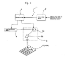
- FIGS. 1 and 2 are conceptional views for explaining a constitution of the laser irradiation apparatus 1 used in the present invention.
- the laser irradiation apparatus 1 is made up of data input means 2, control means 3, laser oscillating means 4, an optical system 5 including a plurality of mirrors and a lens, and so on.
- the data input means 2 performs input of data concerning a pattern such as a character or a symbol (solid data), and storage of input data.
- the input data is input, for example, in a form of CAD data prepared by a computer.
- the control means 3 controls operations of the laser oscillating means 4 and the optical system 5 by data input through the above data input means 2 to generate processing data for use in actual process.
- the laser oscillating means 4 oscillates a light of a wavelength of 532 nm as a laser light, which is obtained by half-wavelength conversion of the fundamental wave of a wavelength of 1064 nm of an Nd:YAG laser. This half-wavelength conversion is realized by taking out the second harmonics of the Nd:YAG laser.
- the laser thus constituted is called “second harmonics YAG laser” .
- the laser light of a wavelength of 532 nm is also called “green laser” because it exhibits green color.
- FIG. 2 is a conceptional view showing an example of a constitution of the laser oscillating means 4 in the second harmonics YAG laser (quoted from Haruhiro Kobayashi " Lecture of Laser” , January, 1992/THE NIKKAN KOGYO SHIMBUN, LTD.).
- a near ultraviolet light of a wavelength of 355 nm obtained by taking out the third harmonics of the Nd:YAG laser can be also used.
- This Nd:YAG laser taking out the third harmonics is called "third harmonics YAG laser".
- the constitution of the laser oscillating means 4 in this case is also fundamentally substantially the same as that shown in FIG. 2.
- one of the second to fourth harmonics of a solid laser such as a glass laser doped with Nd (neodymium) ions or a YVO 4 laser, can be also used.
- the optical system 5 is made up of two mirrors (galvano scanners) 5a and 5b rotating in different directions from each other for controlling the irradiation direction of the laser light; a lens (F0 lens) 5c for converging the laser light; and so on.
- the laser irradiation apparatus 1 having the constitution as described above controls operations of the optical system and so on by processing data generated on the basis of input data, controls the three-dimensional position (positions of the respective axes of XYZ) of a beam spot of the laser light and timings of ON/OFF of laser light irradiation with making a relation to each other, and fully automatically performs marking a character, a symbol, or the like, on a metallic film 15 on a top face 12a of a key top 12.
- this laser irradiation apparatus 1 the top face of each key top of a key unit as will be described later is irradiated with a laser light.
- the beam spot (focus) is moved in plane to scan a character, a symbol, or the like, to be drawn.
- the beam spot is moved also in a depth direction of the metallic film.
- the metallic film at the irradiated portion is completely removed or only a surface layer portion of the metallic film at the irradiated portion is removed, and processing for forming a plane aggregation of a large number of very small recessed points (hereinafter simply referred to as " Shibo process" ) is performed to mark a pattern such as a character or a symbol.
- Shibo process processing for forming a plane aggregation of a large number of very small recessed points
- any key top has a metallic film and marking by a laser light is performed to the metallic film in the first example 10 of the key unit and a second example 10A of a key unit as will be described later
- the present invention is not limited to this.
- a key top having at least one or more metallic films and in which marking by a laser light is performed to those may be used.
- a key top is desirably used that has a layer by printing or painting laminated on a surface, and in which marking of a character, a symbol, or the like, is performed to the layer by printing or painting, using a laser light.
- the key unit 10 is made up of a key pad 11 having transparency made of a soft elastomer such as a silicone rubber or a thermoplastic elastomer; and a large number of key tops 12 disposed on the key pad 11.
- FIG. 3 shows the key unit 10 before marking patterns such as characters and symbols.
- FIG. 4 shows the key unit 10 after marking patterns (as an example, those by Arabic characters are shown) 13 such as characters and symbols.
- the key top 12A disposed at the upper center and having the largest profile is used as so-called multidirection key.
- FIG. 6 shows, in vertical section, part of the key unit 10 after marking the patterns 13 such as characters and symbols by the laser irradiation apparatus 1.
- a 0.1 to 30 ⁇ m-thick metallic film 15 has been formed on a top face 12a and side faces 12b of a main body 14 made of a proper transparent synthetic resin by various metallic film formation means such as plating, vapor deposition, sputtering, and CVD (chemical vapor deposition method).
- metal for generating the metallic film 15 is not particularly limited if those metallic film formation means can cope with it. In short, if various conditions such as wear resistance, corrosion resistance, and chemical resistance required for a key top for a mobile device such as a portable telephone are satisfied, then it is balance with requirement on design such as a color tone and texture.
- the material of the main body 14 of the key top 12 is limited to a resin capable of plating (plating grade resin), such as ABS resin, if the metallic film 15 is formed by plating.
- a resin capable of plating such as ABS resin
- various metallic film formation means such as vapor deposition, sputtering, and CVD, except plating
- various transparent resins such as PC (polycarbonate) resin and PET (polyethylene terephthalate) resin, can be widely used.
- a not-shown overcoat by a UV (ultraviolet) setting resin paint or the like is applied on the metallic film 15. Because this overcoat is removed together with the metallic film 15 at the irradiated portion by irradiation with the laser light 16, it is desirable to be applied on the surface of the key top 12 after processing by the laser light 16.
- a pattern 13 such as a character or a symbol has been formed by completely removing the metallic film 15 at the irradiated portion by irradiation with the laser light 16 by the above laser irradiation apparatus 1 so that the surface of the main body 14 made of a synthetic resin below the metallic film 15 can be exposed and seen when the key top 13 is viewed from above.
- a colored layer 17 of a proper color has been formed by a printing method or a painting method, such as screen printing, pad printing (padding), impregnation printing, or spray painting.
- the above colored layer 17 may be formed on the top face of the key top 12 immediately below the metallic film 15 (the surface of the main body 14) before formation of the metallic film 15, other than the formation on the bottom face 12c of the key top 12.
- the above colored layer 17 is unnecessary when the illuminated character is not colored.
- the metallic film 15 has a thickness within a range of about 1 to 30 ⁇ m though the thickness varies in accordance with the formation method. That is, in case of formation by vapor deposition, sputtering, CVD, or the like, the thickness of the metallic film 15 is relatively thin and a layer made of one kind of metal of 1 ⁇ m or less.
- the metallic film 15 has a multilayer structure in which plating layers of, for example, a 0.2 to 1 ⁇ m-thick electroless nickel plating layer at the lowermost layer, an about 7 to 15 ⁇ m-thick electro copper plating layer at the lower layer, a 4 to 8 ⁇ m-thick nickel electro plating layer at the upper layer, and a 0.1 to 2 ⁇ m-thick plating layer of chromium, gold, or the like, at the uppermost layer.
- the above lower layer of electroless plating has a pinholeless structure for preventing leakage of light.
- there are many kinds in the structure of the plating layer and the present invention is not limited to the above structure.
- a layer formed on the main body 14 of the key top 12 made of an adequate synthetic resin has a multilayer structure as follows. That is, the above multilayer structure is made up of, for example, a 10 to 20 ⁇ m-thick base (under) coat layer as the lowermost layer applied on the main body 14, the metallic film 15 of 1 ⁇ m or less formed by vapor deposition on the base coat layer, and a 10 to 20 ⁇ m-thick transparent overcoat layer applied on the metallic film 15.
- the metallic film 15 is formed by sputtering or CVD, like the above, a layer formed on the main body 14 of the key top 12 made of an adequate synthetic resin has a multilayer structure as follows. That is, the above multilayer structure is made up of, for example, the metallic film 15 of 1 ⁇ m or less formed by sputtering or CVD directly on the resin constituting the main body 14, and a 10 to 20 ⁇ m-thick transparent overcoat layer applied on the metallic film 15.
- the metallic film 15 is formed by metallic film formation means in which the film thickness is relatively thin, such as vapor deposition, sputtering, CVD, or the like, by applying an overcoat by a UV setting resin paint or the like on the metallic film 15, the wear resistance, corrosion resistance, and so on, of the metallic film 15 can be improved.
- a colored transparent paint for the overcoat the metallic film 15 can also be colored into an arbitrary color.
- the key tops 12 each having the above-described structure are fixed to the top face of the key pad 11 with a transparent adhesive 18.
- pressing projections (pressing members )11a (only one is shown) for pressing dome switches 19 (only one is shown) provided to correspond to the respective key tops 12 are integrally formed.
- the above dome switches 19 are disposed on a substrate 20 having an adequate circuit pattern including not-shown fixed contacts.
- a formation process of the pattern 13 such as a character or a symbol in case of the key unit 10 shown in FIG. 6 will be generally described as follows. That is, as shown in FIG. 1, the top face 12a of each key top 12 of the key unit 10 is irradiated using the above green laser as the laser light 16 applied from the laser irradiation apparatus 1. And, as shown in FIG. 5, the beam spot diameter is throttled into 10 to 30 ⁇ m on the surface of the metallic film 15, and the metallic film 15 is scanned along the plane shape of the pattern 13 such as a character or a symbol to be formed.
- the metallic film 15 at the irradiated portion is completely removed into the shape of the pattern 13 such as a character or a symbol to expose the main body portion 14.
- a YAG laser having a wavelength of 1064 nm and the convergence diameter of 30 ⁇ m or less to the irradiated portion a YAG laser having a wavelength of 355 nm obtained by taking out the third harmonics, or an excimer laser having a wavelength of 180 nm and the convergence diameter at molecular level to the irradiated portion, can be also used.
- a light from a not-shown light source permeates the key pad 11 having transparency, enters the bottom face of a key top 12 through the colored layer 17, and outgoes from the pattern 13 such as a character or a symbol to the outside.
- the pattern 13 such as a character or a symbol to the outside.
- Shibo process is a process of removing only a surface layer portion of the metallic film 15, in case that the metallic film 15 is formed by metallic film formation means in which the film thickness is relatively thin (the thickness is about 1 ⁇ m or less), such as vapor deposition, sputtering, or CVD, the Shibo process can not cope with it because the thickness is too thin. Therefore, as the metallic film 15 in this case, a metallic layer whose thickness is relatively thick (the thickness is 3 to 30 ⁇ m) by plating or the like is objective.
- FIG. 6 shows, in vertical section, part of a second example 10A of a key unit on which marking has been applied by a Shibo process with a laser light.
- each part structurally the same as that of the key unit 10 in the above first example 1 is denoted by the same reference numeral as that used in the first example, and thereby the description thereof is omitted.
- a formation process of a pattern 21 such as a character or a symbol in case of the key unit 10A will be generally described as follows.
- the top face 12a of each key top 12 of the key unit 10A is irradiated using the above green laser as the laser light 16 applied from the laser irradiation apparatus 1.
- the beam spot diameter is throttled into 10 to 30 ⁇ m on the surface of the metallic film 15, and the metallic film 15 is scanned along the plane shape of the pattern 13 such as a character or a symbol to be formed.
- each very small recess point constituting the pattern 21 such as a character or a symbol is desirably 20 ⁇ m or less at the maximum.
- the above pattern 20 such as a character or a symbol
- a method in which the outline of the character, the symbol, or the like, is subjected to the Shibo process without any change and a method in which a recess is formed by the Shibo process outside the outline of the character, the symbol, or the like, to surround the outline of the character, the symbol, or the like.
- the thickness of the metallic film 15 on the bottom face of the pattern 21 such as a character or a symbol is processed thinly to the degree of having a metallic feeling without losing the transparency, the light from the light source having entered from the bottom face 12c of the key top 12 can outgo from the pattern 21 such as a character or a symbol, and the character, the symbol, or the like, can be a illumination type.
- the character, the symbol, or the like can also be illuminated in an arbitrary color.
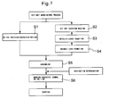
- the key pad 11 and the key tops 12 are formed separately by an adequate molding method such as injection molding (Step S1 and Step S2); further, the metallic film 15 is formed on the top faces 12a and the side faces 12b of the key tops 12 by various metallic film formation means such as plating, vapor deposition, sputtering, and CVD (formation only by plating in case of the key unit 10A) (Step S3); and further, if need, the colored layer 17 is formed on the bottom face 12c of the key top 12 (Step S4). And, finally, the key tops 12 are bonded using the transparent adhesive 18 or the like (Step S5).
- an adequate molding method such as injection molding
- the metallic film 15 is formed on the top faces 12a and the side faces 12b of the key tops 12 by various metallic film formation means such as plating, vapor deposition, sputtering, and CVD (formation only by plating in case of the key unit 10A) (Step S3); and further, if need, the colored layer 17 is
- Step S4 In case that the key top 12 having the metallic film 15 and key tops in each of which a pattern such as a character and a symbol is to be marked on a layer on the surface by printing or painting are mixed in the key unit 10 or 10A, those key tops not having the metallic films 15 do not pass through the above Step S3 and printing or painting on the surface is performed in Step S4.
- Step S6 marking a character, a symbol, or the like, to each key top of the key unit 10 or 10A is performed using the laser irradiation apparatus 1 (Step S6). After completion of this marking step to the key tops 12, the key unit 10 or 10A is shipped solely or with being incorporated in a predetermined mobile device.
- any of the key tops 12 has the metallic film 15, and all characters, symbols, and the like, on those key tops 12 are formed by marking the metallic films 15 with the laser light.
- the present invention is not limited to that.
- the pattern 13 or 20 such as a character or a symbol may be formed on at least one key top 12 by the above marking method.
- the above pattern 13 or 20 such as a character or a symbol differ only in control method of the position of the beam spot in a depth direction of the metallic film 15 on the key top 12 upon irradiation with the laser light, both can be properly mixed on one key unit.
- not all the key tops 12 have the metallic films 15 but the key top 12 having the metallic film 15 and a key top not having the metallic film 15 may be mixed. In case that the key tops different in structure are thus mixed, marking all the patterns such as characters and symbols is desirably unified into one by the laser light using the laser irradiation apparatus 1.
Landscapes
- Engineering & Computer Science (AREA)
- Manufacturing & Machinery (AREA)
- Laser Beam Processing (AREA)
- Push-Button Switches (AREA)
- Manufacture Of Switches (AREA)
- Input From Keyboards Or The Like (AREA)
- Telephone Set Structure (AREA)
Applications Claiming Priority (5)
| Application Number | Priority Date | Filing Date | Title |
|---|---|---|---|
| JP2002307914 | 2002-10-23 | ||
| JP2002307914A JP2005346926A (ja) | 2002-10-23 | 2002-10-23 | 金属メッキ・キーへのマーキング方法及びこれを利用するキーユニットの製造方法 |
| JP2003021271A JP2005342722A (ja) | 2003-01-30 | 2003-01-30 | 金属メッキ・キーへのマーキング方法及びこれを利用するキーユニットの製造方法 |
| JP2003021271 | 2003-01-30 | ||
| PCT/JP2003/013438 WO2004038746A1 (ja) | 2002-10-23 | 2003-10-21 | キーユニット、キートップへのマーキング方法及びこれを利用するキーユニットの製造方法 |
Publications (2)
| Publication Number | Publication Date |
|---|---|
| EP1555682A1 true EP1555682A1 (de) | 2005-07-20 |
| EP1555682A4 EP1555682A4 (de) | 2008-12-24 |
Family
ID=32179081
Family Applications (1)
| Application Number | Title | Priority Date | Filing Date |
|---|---|---|---|
| EP03756733A Withdrawn EP1555682A4 (de) | 2002-10-23 | 2003-10-21 | Schlüsseleinheit, verfahren zur markierung einer schlüsseloberseite und verfahren zur herstellung einer schlüsseleinheit damit |
Country Status (8)
| Country | Link |
|---|---|
| US (1) | US7512229B2 (de) |
| EP (1) | EP1555682A4 (de) |
| JP (1) | JPWO2004038746A1 (de) |
| KR (1) | KR100702886B1 (de) |
| AU (1) | AU2003301628A1 (de) |
| BR (1) | BR0312639A (de) |
| MX (1) | MXPA05000714A (de) |
| WO (1) | WO2004038746A1 (de) |
Cited By (1)
| Publication number | Priority date | Publication date | Assignee | Title |
|---|---|---|---|---|
| KR100761069B1 (ko) | 2006-05-11 | 2007-09-28 | 주식회사 삼영테크놀로지 | 휴대용 단말기의 합성수지 전면 커버 및 그 제조방법 |
Families Citing this family (6)
| Publication number | Priority date | Publication date | Assignee | Title |
|---|---|---|---|---|
| KR100708780B1 (ko) | 2004-03-23 | 2007-04-20 | 주식회사 투엔테크 | 휴대폰의 네비게이션 키패드 금형 제작방법 및 그 금형 |
| JP2006216473A (ja) | 2005-02-07 | 2006-08-17 | Sunarrow Ltd | 薄型キーシート |
| JP4961959B2 (ja) * | 2006-11-13 | 2012-06-27 | パナソニック株式会社 | スイッチの製造方法 |
| JP6520315B2 (ja) * | 2015-03-31 | 2019-05-29 | ブラザー工業株式会社 | キー入力ユニット、その製造方法、及び画像記録装置 |
| DE102017111211B4 (de) | 2017-05-23 | 2023-10-12 | Automotive Lighting Reutlingen Gmbh | Verfahren zur Material abtragenden Laserbearbeitung eines Werkstücks |
| CN119734021B (zh) * | 2025-01-24 | 2025-10-21 | 博众精工科技股份有限公司 | 手机按键装配定位装置、焊接设备及焊接方法 |
Family Cites Families (15)
| Publication number | Priority date | Publication date | Assignee | Title |
|---|---|---|---|---|
| JPH0729209B2 (ja) | 1990-05-31 | 1995-04-05 | 信越ポリマー株式会社 | 透光性表示体 |
| JPH05282956A (ja) * | 1992-03-31 | 1993-10-29 | Shinano Polymer Kk | ゴム製スイッチ用カバー部材の製造方法 |
| DE4212423C2 (de) * | 1992-04-14 | 2001-08-30 | Bayer Ag | Verfahren zur Herstellung von Bedienelementen mit hinterleuchtbaren Symbolen |
| JPH07288054A (ja) | 1994-04-19 | 1995-10-31 | San Aroo Kk | ラバ−キ−のメタル接点及びその製造方法 |
| JP2893445B2 (ja) * | 1997-02-18 | 1999-05-24 | サンアロー株式会社 | 照光式キー及びその製造方法 |
| JPH1127362A (ja) * | 1997-06-30 | 1999-01-29 | San Arrow Kk | 照光式キー及びその製造方法 |
| JP3975516B2 (ja) * | 1997-08-19 | 2007-09-12 | サンアロー株式会社 | 照光式キー及びその製造方法 |
| JPH11110103A (ja) * | 1997-09-10 | 1999-04-23 | Xuli Co Ltd | 透光性金属めっき膜キーキャップ |
| MY121337A (en) * | 1997-10-14 | 2006-01-28 | Shinetsu Polymer Co | Method for forming pad character in push button switch and method for manufacturing cover member for push button switch |
| JP4329136B2 (ja) * | 1998-08-27 | 2009-09-09 | 凸版印刷株式会社 | マーキング方法 |
| JP2001053356A (ja) | 1999-08-09 | 2001-02-23 | Ushio Sogo Gijutsu Kenkyusho:Kk | 加工用レーザ装置に用いられる結晶保持装置 |
| JP2001073154A (ja) | 1999-09-06 | 2001-03-21 | Hitachi Cable Ltd | 部分めっきプラスチック成形体の製造方法 |
| JP4318835B2 (ja) * | 2000-03-31 | 2009-08-26 | 昭和電工株式会社 | 磁気記録媒体、および磁気記録再生装置 |
| JP2002117741A (ja) | 2000-10-10 | 2002-04-19 | Shin Etsu Polymer Co Ltd | レーザー刻印付きキートップ部材 |
| JP2002270059A (ja) | 2001-03-09 | 2002-09-20 | Shin Etsu Polymer Co Ltd | 押釦スイッチ用カバー部材及びその製造方法 |
-
2003
- 2003-10-21 US US10/524,161 patent/US7512229B2/en not_active Expired - Fee Related
- 2003-10-21 BR BR0312639-0A patent/BR0312639A/pt not_active IP Right Cessation
- 2003-10-21 WO PCT/JP2003/013438 patent/WO2004038746A1/ja not_active Ceased
- 2003-10-21 MX MXPA05000714A patent/MXPA05000714A/es unknown
- 2003-10-21 AU AU2003301628A patent/AU2003301628A1/en not_active Abandoned
- 2003-10-21 KR KR1020057001532A patent/KR100702886B1/ko not_active Expired - Fee Related
- 2003-10-21 JP JP2005501571A patent/JPWO2004038746A1/ja active Pending
- 2003-10-21 EP EP03756733A patent/EP1555682A4/de not_active Withdrawn
Cited By (1)
| Publication number | Priority date | Publication date | Assignee | Title |
|---|---|---|---|---|
| KR100761069B1 (ko) | 2006-05-11 | 2007-09-28 | 주식회사 삼영테크놀로지 | 휴대용 단말기의 합성수지 전면 커버 및 그 제조방법 |
Also Published As
| Publication number | Publication date |
|---|---|
| WO2004038746A1 (ja) | 2004-05-06 |
| US7512229B2 (en) | 2009-03-31 |
| US20080013713A1 (en) | 2008-01-17 |
| KR100702886B1 (ko) | 2007-04-04 |
| JPWO2004038746A1 (ja) | 2006-02-23 |
| EP1555682A4 (de) | 2008-12-24 |
| MXPA05000714A (es) | 2005-10-05 |
| BR0312639A (pt) | 2005-04-19 |
| KR20050050638A (ko) | 2005-05-31 |
| AU2003301628A1 (en) | 2004-05-13 |
Similar Documents
| Publication | Publication Date | Title |
|---|---|---|
| KR20070046179A (ko) | 하프미러 가식을 시행한 키 시트 및 키 톱 | |
| AU677299B2 (en) | Seal manufacturing apparatus | |
| US7512229B2 (en) | Key unit, method for marking key top, and method for manufacturing key unit using the same | |
| US7531765B2 (en) | Glass key top, key top marking method, and method for manufacturing key unit using the same | |
| US7616224B2 (en) | Process of producing key units wherein marking on their tops made of light-transmitting material can be completed later on | |
| CN1329934C (zh) | 键单元,在键帽上打标的方法,和用该打标方法制作键单元的方法 | |
| KR20090030932A (ko) | 미세 패턴 데코레이션 시트 구조 | |
| US20120222947A1 (en) | Keypad structure and method of fabricating the same | |
| KR101683642B1 (ko) | 미세패턴이 형성된 카드 | |
| CN101203928B (zh) | 制造便携式终端的键盘的方法 | |
| JP2005342722A (ja) | 金属メッキ・キーへのマーキング方法及びこれを利用するキーユニットの製造方法 | |
| KR200388966Y1 (ko) | 무선단말기의 키패드 | |
| TWI845054B (zh) | 用於觸控顯示面板之塑料面板的製造方法及結構 | |
| JP2004202916A (ja) | 文字や模様等の表示部を有する加飾成形体 | |
| JP2014168927A (ja) | 平板状セキュリティカード用転写原版、平板状セキュリティカード用転写原版の製造方法およびセキュリティカードの製造方法 | |
| JP3108634B2 (ja) | 点字標示シートとその製造方法 | |
| JPH11144551A (ja) | キートップ部材の製造方法および押釦スイッチ用カバー部材の製造方法 | |
| CN114981749B (zh) | 用于电子设备的三维无缝有色盖板 | |
| JP2009274455A (ja) | フィルム付着体およびそのフィルム付着体の製造方法 | |
| US20110156295A1 (en) | Embossing assembly, manufacturing method thereof, and embossing method using the same | |
| WO2003060613A1 (fr) | Montre photovoltaique et procede de production d'une plaque reflechissante utilisee dans une montre photovoltaique | |
| KR20060114480A (ko) | 금속키 및 금속 키패드의 제조 방법 | |
| CN121536100A (zh) | 渐变智能移动终端背壳饰面件的制作方法及智能移动终端 | |
| CN1953113A (zh) | 按键片的制造方法 | |
| JP2000215748A (ja) | 照光式シ―ト状キ―トップ |
Legal Events
| Date | Code | Title | Description |
|---|---|---|---|
| PUAI | Public reference made under article 153(3) epc to a published international application that has entered the european phase |
Free format text: ORIGINAL CODE: 0009012 |
|
| 17P | Request for examination filed |
Effective date: 20050413 |
|
| AK | Designated contracting states |
Kind code of ref document: A1 Designated state(s): AT BE BG CH CY CZ DE DK EE ES FI FR GB GR HU IE IT LI LU MC NL PT RO SE SI SK TR |
|
| AX | Request for extension of the european patent |
Extension state: AL LT LV MK |
|
| DAX | Request for extension of the european patent (deleted) | ||
| A4 | Supplementary search report drawn up and despatched |
Effective date: 20081124 |
|
| 18D | Application deemed to be withdrawn |
Effective date: 20110501 |
|
| STAA | Information on the status of an ep patent application or granted ep patent |
Free format text: STATUS: THE APPLICATION IS DEEMED TO BE WITHDRAWN |
|
| R18D | Application deemed to be withdrawn (corrected) |
Effective date: 20110503 |