EP1555434A1 - Membranpumpe - Google Patents
Membranpumpe Download PDFInfo
- Publication number
- EP1555434A1 EP1555434A1 EP04025738A EP04025738A EP1555434A1 EP 1555434 A1 EP1555434 A1 EP 1555434A1 EP 04025738 A EP04025738 A EP 04025738A EP 04025738 A EP04025738 A EP 04025738A EP 1555434 A1 EP1555434 A1 EP 1555434A1
- Authority
- EP
- European Patent Office
- Prior art keywords
- membrane
- annular
- drive element
- diaphragm pump
- pump according
- Prior art date
- Legal status (The legal status is an assumption and is not a legal conclusion. Google has not performed a legal analysis and makes no representation as to the accuracy of the status listed.)
- Granted
Links
- 239000012528 membrane Substances 0.000 claims abstract description 110
- 230000002093 peripheral effect Effects 0.000 claims abstract description 5
- 230000005540 biological transmission Effects 0.000 claims description 13
- 239000011324 bead Substances 0.000 claims description 8
- 238000004073 vulcanization Methods 0.000 claims description 8
- 230000033001 locomotion Effects 0.000 claims description 5
- 239000000463 material Substances 0.000 claims description 5
- 230000000087 stabilizing effect Effects 0.000 claims description 4
- 229910000831 Steel Inorganic materials 0.000 claims description 3
- 230000008878 coupling Effects 0.000 claims description 3
- 238000010168 coupling process Methods 0.000 claims description 3
- 238000005859 coupling reaction Methods 0.000 claims description 3
- 239000002184 metal Substances 0.000 claims description 3
- 239000004033 plastic Substances 0.000 claims description 3
- 230000002787 reinforcement Effects 0.000 claims description 3
- 239000010959 steel Substances 0.000 claims description 3
- 239000011248 coating agent Substances 0.000 claims description 2
- 238000000576 coating method Methods 0.000 claims description 2
- 239000004810 polytetrafluoroethylene Substances 0.000 claims description 2
- 229920001343 polytetrafluoroethylene Polymers 0.000 claims description 2
- 238000010276 construction Methods 0.000 description 3
- 238000004519 manufacturing process Methods 0.000 description 3
- 239000013013 elastic material Substances 0.000 description 2
- 230000007246 mechanism Effects 0.000 description 2
- 238000007493 shaping process Methods 0.000 description 2
- 239000000853 adhesive Substances 0.000 description 1
- 230000001070 adhesive effect Effects 0.000 description 1
- 230000008859 change Effects 0.000 description 1
- 230000001427 coherent effect Effects 0.000 description 1
- 230000006835 compression Effects 0.000 description 1
- 238000007906 compression Methods 0.000 description 1
- 238000006073 displacement reaction Methods 0.000 description 1
- 238000005516 engineering process Methods 0.000 description 1
- 239000012530 fluid Substances 0.000 description 1
- 239000000446 fuel Substances 0.000 description 1
- 239000007789 gas Substances 0.000 description 1
- 238000009434 installation Methods 0.000 description 1
- 239000007788 liquid Substances 0.000 description 1
- 230000007774 longterm Effects 0.000 description 1
- 230000014759 maintenance of location Effects 0.000 description 1
- 238000005086 pumping Methods 0.000 description 1
- 230000009467 reduction Effects 0.000 description 1
- 230000006641 stabilisation Effects 0.000 description 1
- 238000011105 stabilization Methods 0.000 description 1
- 230000007704 transition Effects 0.000 description 1
Images

Classifications
-
- F—MECHANICAL ENGINEERING; LIGHTING; HEATING; WEAPONS; BLASTING
- F04—POSITIVE - DISPLACEMENT MACHINES FOR LIQUIDS; PUMPS FOR LIQUIDS OR ELASTIC FLUIDS
- F04B—POSITIVE-DISPLACEMENT MACHINES FOR LIQUIDS; PUMPS
- F04B43/00—Machines, pumps, or pumping installations having flexible working members
- F04B43/0009—Special features
- F04B43/0054—Special features particularities of the flexible members
-
- F—MECHANICAL ENGINEERING; LIGHTING; HEATING; WEAPONS; BLASTING
- F04—POSITIVE - DISPLACEMENT MACHINES FOR LIQUIDS; PUMPS FOR LIQUIDS OR ELASTIC FLUIDS
- F04B—POSITIVE-DISPLACEMENT MACHINES FOR LIQUIDS; PUMPS
- F04B43/00—Machines, pumps, or pumping installations having flexible working members
- F04B43/02—Machines, pumps, or pumping installations having flexible working members having plate-like flexible members, e.g. diaphragms
Definitions
- the invention relates to a diaphragm pump with an annular working space and a annular membrane attached to its outer Peripheral area and at its inner edge area is clamped, with the inner and the outer Membrane clamping point relative to each other are stationary and being between the outer and internal clamping point with a pump drive connected drive element for the deflection of annular membrane attacks.
- the diameter of the membrane very small is a vulcanization of Stahlpleuels, which thereby under Circumstances have a diameter of less than 1 mm, very difficult. Besides, it's one of those Miniaturization also difficult, the hydraulic or pneumatic connections to the intake and exhaust valves of the work space. Despite the very small Dimensions of the diaphragm with a diameter of Example 5 mm would work at a working speed of 3000 Revolutions per minute and a stroke of 0.8 mm already one Delivered amount of about 25 ml per minute. In many In some cases, it would be desirable to have acceptable, still easily manageable size of the pump these or even to realize lower flow rates.
- the invention proposes in particular that in a diaphragm pump with an annular working space and an annular membrane, the drive element of the ring membrane facing the membrane, sleeve or ring is formed with an approximately the annular working space corresponding diameter and with one of its annular End faces transversely to the membrane plane on the side facing the pump drive side of the ring diaphragm for deflection and for transmitting a reciprocating motion on the ring membrane attacks.
- the annular volume of the annular membrane per delivery stroke can be kept small by the annular geometry of the annular membrane and on the other hand, the sleeve-shaped drive element of the annular membrane forms a stable force transmission element, which also allows a secure connection to the annular membrane and also to the pump drive.
- the annular surface of the membrane is smaller than a circular area with the same diameter, so that even with very small pumps for small flow rates, the diameter of the ring membrane can still have a manageable size.
- Such a ring diaphragm pump with a larger diameter of the annular membrane and the likewise annular working space can be made easier and adjusted, because the manufacturing problems are not present due to the otherwise extreme, extreme miniaturization of the components.
- connection of the sleeve-shaped drive element with the annular membrane can be made by the larger diameter of this element with particular repeatable, good accuracy and much less complicated than known diaphragm pumps comparable pump power, the pumping power in particular less than 100ml per minute, for example, less than 50ml can be per minute.
- the drive transmission is so simplified and performed almost directly by the shortest route from the linear actuator to the membrane that they can be accommodated even with very small pumps and can be made stable and reliable despite the cramped space.
- the at least partially sleeve-shaped or annular drive element is attached only on one side of the annular membrane on the side remote from the pump chamber. It is thus the working space facing, continuous dense membrane surface available. This is advantageous in conveying aggressive media because virtually no points of attack are present due to the smooth surface and the side of the membrane facing the working space can be protected continuously by an uninterrupted coating, in particular made of PTFE.
- the sleeve or annular drive element is preferably connected by vulcanization with the annular membrane. This creates a durable connection.
- a positive and / or non-positive connection comes into question.
- the annular diaphragm is expediently clamped in a force-fitting manner at the inner membrane clamping point between a pump head part having the annular working space and a clamping part connectable therewith and / or held in a form-fitting manner.
- the arranged at the inner membrane clamping point clamping member may be connected by a preferably central screw with the pump head part. This central attachment of the ring diaphragm allows easy and quick installation and a good seal in this area.
- the positive retention of the membrane optionally in combination with a non-positive support avoids undesirable deformation of the membrane.
- the clamping member at the inner membrane Einspanstelle is conveniently located within the annular space formed substantially by the sleeve-shaped drive element.
- the existing annulus is utilized to accommodate the clamping part to save space.
- the clamping part may be connected to the annular membrane by vulcanization.
- the ring diaphragm and the clamping part form a coherent component in this embodiment.
- the sleeve-shaped drive element is connected by vulcanization with the annular membrane, all three components form a unit, so that a simplified assembly is favored. Due to the vulcanized inner clamping part, a tight and stable connection of both components can be achieved without additional structural means.
- the drive element may be integrally connected to the diaphragm and have a connection for coupling with the pump drive.
- This embodiment of the membrane has no separate part, which is provided as a connecting element between the actual membrane and the pump drive, but the membrane continues on the underside or drive side in one piece with an initially sleeve-like part to the eccentric drive, where a corresponding shaping to form a Connection for coupling with the drive is present.
- the direct connection in the region of the eccentric or a crank mechanism can preferably take place via a plastic or metal part integrated (vulcanised in) in this area.
- This embodiment of the membrane with integrally molded connecting element is particularly simple and by the sleeve-like, one-piece continuation following the membrane sufficient compressive and tensile forces can be transmitted. At least for the transport of gases, the transferable forces are sufficient.
- reinforcements made of rigid material may be integrated into the drive element consisting of the material of the diaphragm at least in some areas. As a result, higher compressive and tensile forces can be transmitted.
- a sleeve-shaped or annular, consisting of metal drive element as a reinforcement can be substantially completely embedded in the elastomeric membrane material, with either a continuation of rubber-elastic material to the eccentric connects to the drive-side end of the sleeve or annular drive element or as an additional continuation Transmission element is provided.
- the ring membrane is also on its outer edge between the annular workspace having pump head part and a connectable housing part frictionally clamped and / or held form-fitting. This is also true in the outer peripheral region of the ring membrane a dense and at a positive mount a virtually stress-free Bracket available.
- Ring membrane a preferably annular circumferential, rib-like connection and Stabilisierwulst on, with the sleeve or annular end of the drive element is connected and that the drive element in Connection area preferably in the connection and Stabilizing bulge intervenes or there vulcanised.
- the pump drive is an eccentric drive formed, the one with the sleeve-shaped drive element connected to the end facing away from the annular membrane Has transmission element.
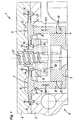
- diaphragm pump 1 has within a pump head 2 a ring diaphragm 3, which is clamped at its outer peripheral region between housing parts 4.5 and at its inner edge region between the housing part 4 and a clamping part 9.
- the annular diaphragm 3 defines an annular working space 6.
- a pump drive not shown here, is provided, which may preferably be designed as an eccentric drive or crank drive. It has a transmission element 7, which is connected to a sleeve-shaped drive element 8. This is connected at its other end to the ring diaphragm 3.
- the working chamber 6 is connected via inlet and outlet channels, not shown here, to an inlet valve and an outlet valve.
- the valves are preferably designed as plate valves.
- the ring diaphragm 3 and the drive element 8 connected thereto are shown in FIGS. 2 to 4.
- the ring diaphragm 3 is preferably connected to an end face of the sleeve-shaped drive element 8 by vulcanization.
- the annular diaphragm 3 consists of a rubber-elastic material, while the drive element 8 is formed for example by a steel sleeve.
- the drive element 8 is vulcanized into the annular membrane 3 and engages with a front end something in a groove 10 at the diaphragm bottom.
- an annular circumferential, rib-like connection and Stabilisierwulst 11 is provided, in particular in order to bring the pressure and train transmission from the drive element 8 better in the membrane.
- the connecting and stabilizing bead 11 is arranged approximately in a concentric region in the middle between outer edge 12 and inner edge 13 of the annular width of the annular membrane 3.
- Fig. 1 is also clearly visible that the annular membrane 3 is arranged to the working space 6 so that an approximately central orientation of the drive element 8 and the connecting and stabilizing bead 11 is present to the working space 6.
- the annular membrane is at least partially deformed into the working space 6, so that therein located conveying medium is displaced.
- the shaping of the working space 6 and the annular membrane 3 may be provided so that in top dead center, the membrane fills the working space virtually dead space.
- the annular diaphragm 3 is sealed relative to the housing parts 4 and 5 or also the clamping part 9 by an inner bead 14 and by an outer bead 15.
- the beads 14,15 engage in grooves 20,21 of the housing part 5 a.
- the clamping part 9 is located within the formed by the sleeve-shaped drive element 8 annulus 18, so that this space exploited is. Overall, by the direct drive transmission of an eccentric drive on the membrane and also by the space-saving arrangement of the clamping part 9 within the Annular space 18 realized a pump with low height become.
- the adjoining the drive element 8 transmission element 7 may be a plastic part, which at its end facing the drive element 8 has a lug 19 on which the sleeve-like drive element 8 can be plugged and optionally connected by press fit or adhesive bond.
- the clamping part 9 can also be connected to the ring membrane by vulcanization, so that a component consisting of three parts is formed together with the drive element 8. There are then only a few assembly parts that can be assembled in a short time.
- the diaphragm pump 1 is preferably as a feed pump for low flow rates at comparatively high stroke frequency educated. For example, this allows flow rates of 25 ml per minute, with 3000 strokes per minute can be provided. The high number of strokes is required so that the valves work exactly and the tolerances of Valve sections must not be set too tight.
- a miniature pump can in Figs. 3 and 4 in perspective together with the drive element 8 shown annular membrane 3, for example, have an outer diameter of 10 mm, so that the illustrations in Fig. 3 and 4 about a scale of 5: 1.
- the sleeve-shaped drive element 8 preferably has a continuous wall, but optionally also may have a wall provided with recesses or formed by at least partially by rods or fingers wall, so that a corresponding mass reduction or access to the inner annulus exist is. It should also be mentioned that although the annular membrane 3 preferably has a circular shape, it may also have a different shape.
- the attacking drive element 8 and the leading to the drive continuation of the membrane or the at least in the terminal region in the membrane preferably the same shapes as the membrane and thereby in particular as the working space 6 facing area or may be designed differently ,
- the annular membrane may have an elliptical shape as a whole or in some regions, which results in advantages in conjunction with a crank mechanism and the associated pendulum movement of the drive element.
- the pendulum movement preferably runs in the direction of the minor axis of the ellipse.
- the diaphragm pump 1 according to the invention is in particular created a high-speed membrane-liquid pump, in which a combination of high number of strokes at the same time low flow rate is present and still structurally simple and stable in construction.
- Such Diaphragm pumps 1 are mainly in laboratories or for Microsystem technology applications can be used.
- the Membranes 2 according to the invention are even smaller Embodiments of the membrane 2 as in the in Figures 2 to 4 possible on a scale of 5: 1.
Landscapes
- Engineering & Computer Science (AREA)
- Mechanical Engineering (AREA)
- General Engineering & Computer Science (AREA)
- Reciprocating Pumps (AREA)
Abstract
Description
Einerseits kann durch die ringförmige Geometrie der Ringmembrane das Fördervolumen bei akzeptablem Durchmesser der Ringmembrane pro Förderhub klein gehalten werden und andererseits bildet das hülsenförmige Antriebselement der Ringmembrane ein stabiles Kraftübertragungselement, welches darüber hinaus eine sichere Anbindung an die Ringmembrane ermöglicht und auch an den Pumpenantrieb.
Die ringförmige Fläche der Membrane ist bei gleichem Durchmesser kleiner als eine Kreisfläche, so dass auch bei Kleinstpumpen für geringe Fördermengen der Durchmesser der Ringmembrane eine noch gut handhabbare Größe aufweisen kann.
Eine solche Ringmembranpumpe mit größerem Durchmesser der Ringmembrane und des ebenfalls ringförmigen Arbeitsraumes kann dadurch leichter hergestellt und justiert werden, weil die Herstellungsprobleme durch die sonst notwendige, extreme Miniaturisierung der Bauelemente nicht vorhanden sind. Vor allem die Verbindung des hülsenförmigen Antriebselements mit der ringförmigen Membrane kann durch den größeren Durchmesser dieses Elements mit insbesondere wiederholbarer, guter Genauigkeit und wesentlich unkomplizierter erfolgen als bei bekannten Membranpumpen vergleichbarer Pumpleistung, wobei die Pumpleistung insbesondere weniger als 100ml pro Minute, zum Beispiel weniger als 50ml pro Minute betragen kann.
Eine solche Konstruktion ist insbesondere für Kleinstpumpen ungeeignet, weil für die Antriebsübertragungselemente nur sehr wenig Platz vorhanden ist und deshalb nur filigrane Dimensionierungen mit entsprechenden Nachteilen bezüglich der Belastbarkeit und Lebensdauer möglich wären. Nachteilig ist weiterhin, dass die Durchbrüche in der Membrane für die sie durchsetzenden Befestigungselemente Schwachstellen bezüglich einer langfristigen Dichtigkeit bilden. Außerdem müsste beim Fördern aggressiver Medien dafür Sorge getragen werden, dass alle im Arbeitsraum befindlichen Teile, also Membrane beziehungsweise Membranoberfläche, Klemmring und dessen Befestigungsmittel und dergleichen diesen aggressiven Medien widerstehen. Durch den in den Arbeitsraum ragenden Klemmring kann die Strömung des Fördermediums gestört werden. Schließlich weist diese Pumpe in nachteiliger Weise ein vergleichsweise großes Totraumvolumen auf.
Bevorzugt ist vorgesehen, dass das zumindest bereichsweise hülsen- oder ringförmige Antriebselement nur an einer Seite der Ringmembrane an der dem Pumpenraum abgewandten Seite befestigt ist.
Es steht somit die dem Arbeitsraum zugewandte, durchgehend dichte Membranoberfläche zur Verfügung. Dies ist beim Fördern aggressiver Medien vorteilhaft, weil durch die glatte Oberfläche praktisch keine Angriffsstellen vorhanden sind und die dem Arbeitsraum zugewandte Seite der Membrane durchgehend durch eine ununterbrochene Beschichtung insbesondere aus PTFE geschützt werden kann.
Das hülsen- oder ringförmige Antriebselement ist vorzugsweise durch Vulkanisieren mit der Ringmembrane verbunden. Dadurch ist eine haltbare Verbindung gebildet. Gegebenenfalls kommt auch eine form- und/oder kraftschlüssig Verbindung in Frage.
Dabei kann das bei der inneren Membran-Einspanstelle angeordnete Klemmteil durch eine vorzugsweise zentrale Schraubverbindung mit dem Pumpenkopfteil verbunden sein.
Diese zentrale Befestigung der Ringmembrane ermöglicht eine einfache und schnelle Montage und eine gute Abdichtung in diesem Bereich. Die formschlüssige Halterung der Membrane gegebenenfalls in Kombination mit einer kraftschlüssigen Halterung vermeidet unerwünschte Verformungen der Membrane.
Das Klemmteil bei der inneren Membran-Einspanstelle befindet sich zweckmäßigerweise innerhalb des im wesentlichen durch das hülsenförmige Antriebselement gebildeten Ringraums. Somit wird der vorhandene Ringraum ausgenutzt um das Klemmteil platzsparend unterzubringen.
Nach einer Weiterbildung der Erfindung kann das Klemmteil mit der Ringmembrane durch Vulkanisieren verbunden sein. Die Ringmembrane und das Klemmteil bilden bei dieser Ausführung ein zusammenhängendes Bauteil. Wenn auch das hülsenförmige Antriebselement durch Vulkanisieren mit der Ringmembrane verbunden ist, bilden alle drei Bauelemente eine Einheit, so dass eine vereinfachte Montage begünstigt ist.
Durch das anvulkanisierte innere Klemmteil kann ohne zusätzliche konstruktive Mittel eine dichte und stabile Verbindung beider Bauteile erreicht werden.
Diese Ausführungsform der Membrane weist kein separates Teil auf, das als Verbindungselement zwischen der eigentlichen Membrane und dem Pumpenantrieb vorgesehen ist, sondern die Membrane setzt sich unterseitig beziehungsweise antriebsseitig einstückig mit einem zunächst hülsenartigen Teil bis zu dem Exzenterantrieb fort, wo eine entsprechende Formung zur Bildung eines Anschlusses zum Koppeln mit dem Antrieb vorhanden ist. Die direkte Verbindung im Bereich des Exzenters oder eines Kurbeltriebs kann vorzugsweise über ein in diesem Bereich integriertes (einvulkanisiertes) Kunststoff- oder Metallteil erfolgen.
Diese Ausführungsform der Membrane mit einstückig angeformtem Verbindungselement ist besonders einfach und durch die hülsenartige, einstückige Fortsetzung im Anschluss an die Membrane können ausreichende Druck- und Zugkräfte übertragen werden. Zumindest zum Fördern von Gasen reichen die übertragbaren Kräfte aus.
Zur Stabilisierung kann in das aus dem Material der Membrane bestehende Antriebselement zumindest bereichsweise Armierungen aus biegesteifem Material integriert sein.
Dadurch können auch höhere Druck- und Zugkräfte übertragen werden. Dabei kann ein hülsen- oder ringförmiges, aus Metall bestehendes Antriebselement als Armierung weitgehend vollständig in das gummielastische Membranmaterial eingebettet sein, wobei sich an das antriebsseitige Ende des hülsen- oder ringförmigen Antriebselementes entweder eine Fortsetzung aus gummielastischem Material bis zum Exzenter anschließt oder als Fortsetzung ein zusätzliches Übertragungselement vorgesehen ist.
Nachstehend ist die Erfindung anhand der Zeichnungen noch näher beschrieben.
Es zeigt in zum Teil schematisierter Darstellung:
- Fig. 1
- eine stark vergrößerte Teildarstellung einer erfindungsgemäßen Membranpumpe im Querschnitt,
- Fig. 2
- eine vergrößerte Darstellung einer erfindungsgemäßen Ringmembrane im Querschnitt mit einem verbundenen hülsenförmigen Antriebselement,
- Fig. 3
- eine perspektivische Unteransicht der in Fig 2 gezeigten Ringmembrane und
- Fig. 4
- eine perspektivische Oberseitenansicht der in Fig 2 gezeigten Ringmembrane.
Die Ringmembrane 3 und das damit verbundene Antriebselement 8 sind in den Figuren 2 bis 4 dargestellt.
Bei einer Hubbewegung des hülsenförmigen Übertragungselementes 8 entsprechend dem Pfeil Pf1 wird die Ringmembrane zumindest teilweise in den Arbeitsraum 6 verformt, so dass darin befindliches Fördermedium verdrängt wird. Bedarfsweise kann die Formung des Arbeitsraums 6 und der Ringmembrane 3 so vorgesehen sein, dass in oberer Totpunktlage die Membrane den Arbeitsraum praktisch totraumfrei ausfüllt.
Die Ringmembrane 3 wird gegenüber den Gehäuseteilen 4 und 5 beziehungsweise auch dem Klemmteil 9 durch einen inneren Wulst 14 und durch einen äußeren Wulst 15 abgedichtet. Die Wülste 14,15 greifen in Nuten 20,21 des Gehäuseteils 5 ein.
Das Klemmteil 9 kann gegebenenfalls auch durch Vulkanisieren mit der Ringmembrane verbunden sein, so dass zusammen mit dem Antriebselement 8 ein aus drei Teilen bestehendes Bauelement gebildet ist. Es ergeben sich dann nur wenige Montageteile, die in kurzer Zeit zusammengebaut werden können.
Weiterhin sei erwähnt, dass die ringförmige Membrane 3 zwar bevorzugt eine kreisrunde Form hat, jedoch auch eine davon abweichende Form haben kann. Gleiches gilt für das daran angreifende Antriebselement 8 beziehungsweise die zum Antrieb führende Fortsetzung der Membrane, das beziehungsweise die zumindest im Anschlussbereich bei der Membrane vorzugsweise jeweils gleiche Formen wie die Membrane und dabei insbesondere wie deren dem Arbeitsraum 6 zugewandter Bereich oder auch davon abweichend ausgebildet sein können. Beispielsweise kann die ringförmige Membrane insgesamt oder bereichsweise eine elliptische Form aufweisen, was Vorteile in Verbindung mit einem Kurbeltrieb und der damit verbundenen Pendelbewegung des Antriebselementes ergibt. Die Pendelbewegung verläuft dabei vorzugsweise in Richtung der kleinen Achse der Ellipse.
Auch besteht die Möglichkeit, den den Arbeitsraum 6 begrenzenden Ringbereich der Membrane 3 und den Außenrandbereich 12 unterschiedlich zu gestalten.
Claims (18)
- Membranpumpe (1) mit einem ringförmigen Arbeitsraum (6) und einer ringförmigen Membrane (3), die an ihrem äußeren Umfangsbereich (12) und an ihrem inneren Randbereich (13) eingespannt ist, wobei die innere und die äußere Membran-Einspannstelle relativ zueinander feststehend sind und wobei zwischen der äußeren und inneren Einspannstelle ein mit einem Pumpenantrieb verbundenes Antriebselement (8) zur Auslenkung der ringförmigen Membrane (3) angreift, wobei das Antriebselement (8) der Membrane zugewandt hülsen- oder ringförmig mit einem etwa dem ringförmigen Arbeitsraum (6) entsprechenden Durchmesser ausgebildet ist und mit einer seiner ringförmigen Stirnseiten quer zur Membranebene an der dem Pumpenantrieb zugewandten Seite der Ringmembrane (3) zur Auslenkung und zur Übertragung einer Hin- und Herbewegung an der Ringmembrane (3) angreift.
- Membranpumpe nach Anspruch 1, dadurch gekennzeichnet, dass das zumindest bereichsweise hülsenförmige Antriebselement (8) nur an einer Seite der Ringmembrane (3) an der dem Arbeitsraum (6) abgewandten Seite befestigt ist.
- Membranpumpe nach Anspruch 1 oder 2, dadurch gekennzeichnet, dass das hülsenförmige Antriebselement (8) als Zylinderhülse mit durchgehender Wandung oder mit Aussparungen aufweisender Wandung oder mit einer wenigstens bereichsweise durch Stäbe oder Finger gebildeten Wandung ausgebildet ist.
- Membranpumpe nach einem der Ansprüche 1 bis 3, dadurch gekennzeichnet, dass der Pumpenantrieb vorzugsweise als Exzenterantrieb ausgebildet ist, der ein mit dem hülsenförmigen Antriebselement (8) an dessen der Ringmembrane (3) abgewandten Ende verbundenes Übertragungselement (7) aufweist.
- Membranpumpe nach einem der Ansprüche 1 bis 4, dadurch gekennzeichnet, dass die Ringmembrane (3) bei der inneren Membran-Einspanstelle zwischen einem den ringförmigen Arbeitsraum (6) aufweisenden Pumpenkopfteil (4) und einem damit verbindbaren Klemmteil (9) kraftschlüssig eingespannt und/oder formschlüssig gehalten ist.
- Membranpumpe nach Anspruch 5, dadurch gekennzeichnet, dass das bei der inneren Membran-Einspanstelle angeordnete Klemmteil (9) durch eine vorzugsweise zentrale Schraubverbindung mit dem Pumpenkopfteil (4) verbunden ist.
- Membranpumpe nach Anspruch 5 oder 6, dadurch gekennzeichnet, dass das Klemmteil (9) mit der Ringmembrane (3) durch Vulkanisieren verbunden ist.
- Membranpumpe nach einem der Ansprüche 5 bis 7, dadurch gekennzeichnet, dass sich das Klemmteil (9) bei der inneren Membran-Einspanstelle innerhalb des im wesentlichen durch das zumindest bereichsweise hülsenförmige Antriebselement (8) gebildeten Ringraums (18) befindet.
- Membranpumpe nach einem der Ansprüche 1 bis 8, dadurch gekennzeichnet, dass die Ringmembrane (3) an ihrem Außenrand (12) zwischen dem den ringförmigen Arbeitsraum (3) aufweisenden Pumpenkopfteil und einem damit verbindbaren Gehäuseteil kraftschlüssig eingespannt und/oder formschlüssig gehalten ist.
- Membranpumpe nach einem der Ansprüche 1 bis 9, dadurch gekennzeichnet, dass das zumindest membranseitig hülsenoder ringförmige Antriebselement (8) mit seiner der Ringmembrane (3) zugewandten, ringförmigen Stirnseite etwa in Verlängerung einer den ringförmigen Arbeitsraum (6) etwa mittig schneidenden, konzentrischen Ringfläche an der Ringmembrane angreift.
- Membranpumpe nach einem der Ansprüche 1 bis 10, dadurch gekennzeichnet, dass die Ringmembrane (3) eine vorzugsweise ringförmig umlaufende, rippenartige Anschluss- und Stabilisierwulst (11) aufweist, die mit dem hülsen- oder ringförmigen Ende des Antriebselementes (8) verbunden ist und dass das Antriebselement im Verbindungsbereich vorzugsweise in den Anschluss- und Stabilisierwulst eingreift.
- Membranpumpe nach einem der Ansprüche 1 bis 11, dadurch gekennzeichnet, dass die dem Arbeitsraum (6) zugewandte Seite der Ringmembrane (3) eine vorzugsweise durchgehende Beschichtung insbesondere aus PTFE aufweist.
- Membranpumpe nach einem der Ansprüche 1 bis 12, dadurch gekennzeichnet, dass das hülsenförmige Antriebselement (8) vorzugsweise durch Vulkanisieren und/oder formund/oder kraftschlüssig mit der Ringmembrane (3) verbunden ist.
- Membranpumpe nach einem der Ansprüche 1 bis 13, dadurch gekennzeichnet, dass das hülsenförmige Antriebselement (8) aus Metall, vorzugsweise Stahl und das damit verbindbare Übertragungselement (7) vorzugsweise aus Kunststoff bestehen.
- Membranpumpe nach einem der Ansprüche 1 bis 14, dadurch gekennzeichnet, dass die Ringmembrane (3) an ihrem Außenrand (12) eine Außenwulst (15) und am inneren Rand eine Innenwulst (14) aufweist.
- Membranpumpe nach einem der Ansprüche 1 bis 15, dadurch gekennzeichnet, dass sie als Förderpumpe für geringe Fördermengen im Bereich von vorzugsweise unter 100 ml pro Minute und einer hohen Hubfrequenz von etwa 50 Hz ausgebildet ist.
- Membranpumpe nach einem der Ansprüche 1,2,5 bis 12,15 oder 16, dadurch gekennzeichnet, dass das Antriebselement (8) einstückig mit der Membrane (3) verbunden ist und einen Anschluss zum Koppeln mit dem Pumpenantrieb aufweist.
- Membranpumpe nach Anspruch 17, dadurch gekennzeichnet, dass in das aus dem Material der Membrane (3) bestehende Antriebselement (8) zumindest bereichsweise Armierungen aus biegesteifem Material integriert sind.
Applications Claiming Priority (2)
| Application Number | Priority Date | Filing Date | Title |
|---|---|---|---|
| DE102004002079A DE102004002079A1 (de) | 2004-01-15 | 2004-01-15 | Membranpumpe |
| DE102004002079 | 2004-01-15 |
Publications (2)
| Publication Number | Publication Date |
|---|---|
| EP1555434A1 true EP1555434A1 (de) | 2005-07-20 |
| EP1555434B1 EP1555434B1 (de) | 2006-10-25 |
Family
ID=34609560
Family Applications (1)
| Application Number | Title | Priority Date | Filing Date |
|---|---|---|---|
| EP04025738A Expired - Lifetime EP1555434B1 (de) | 2004-01-15 | 2004-10-29 | Membranpumpe |
Country Status (4)
| Country | Link |
|---|---|
| US (1) | US7373872B2 (de) |
| EP (1) | EP1555434B1 (de) |
| JP (1) | JP5371171B2 (de) |
| DE (2) | DE102004002079A1 (de) |
Families Citing this family (2)
| Publication number | Priority date | Publication date | Assignee | Title |
|---|---|---|---|---|
| US9377017B2 (en) * | 2012-11-15 | 2016-06-28 | Shenzhen Mindray Bio-Medical Electronics Co., Ltd. | Extended elasticity of pump membrane with conserved pump force |
| CN108757409B (zh) * | 2018-07-06 | 2023-08-25 | 珠海格力电器股份有限公司 | 隔膜组件、稳压泵及净水机 |
Citations (4)
| Publication number | Priority date | Publication date | Assignee | Title |
|---|---|---|---|---|
| GB734294A (en) * | 1952-11-05 | 1955-07-27 | George William Webb | Improvements in or relating to pumping apparatus for use with boats |
| US3223045A (en) * | 1959-05-04 | 1965-12-14 | Chrysler Corp | Fuel pump |
| US3241494A (en) * | 1960-01-15 | 1966-03-22 | Acf Ind Inc | Fuel systems |
| US3291064A (en) * | 1963-01-25 | 1966-12-13 | Gen Motors Corp | Diaphragm pump with annular pumping chamber |
Family Cites Families (10)
| Publication number | Priority date | Publication date | Assignee | Title |
|---|---|---|---|---|
| US2731534A (en) * | 1948-02-26 | 1956-01-17 | Taylor Winfield Corp | Fluid pressure actuator for machine components |
| US3008427A (en) * | 1959-02-11 | 1961-11-14 | Gen Motors Corp | Fuel pump |
| US3252424A (en) * | 1960-01-15 | 1966-05-24 | Acf Ind Inc | Fuel systems |
| JPS61160666A (ja) * | 1984-12-29 | 1986-07-21 | Nippon Valqua Ind Ltd | ダイアフラムおよびその製造方法 |
| US5291822A (en) * | 1992-11-16 | 1994-03-08 | Orbital Walbro Corporation | Diaphragm for pressure regulators and method of making |
| DE4244619A1 (de) * | 1992-12-31 | 1994-07-07 | Knf Neuberger Gmbh | Verfahren zum Betreiben einer Membranpumpe sowie Membranpumpe zum Durchführen des Verfahrens |
| US5634391A (en) * | 1996-07-09 | 1997-06-03 | Westinghouse Air Brake Co. | Inert plastic coated flexible type diaphragm for application in a sanitary type pump |
| DE19802443C1 (de) * | 1998-01-23 | 1999-05-12 | Luk Fahrzeug Hydraulik | Pumpe |
| DE19819408A1 (de) | 1998-04-30 | 1999-11-11 | Freudenberg Carl Fa | Membranpumpe zur Förderung von gasförmigen oder flüssigen Medien |
| DE10233561B4 (de) * | 2002-07-24 | 2008-02-21 | Prominent Dosiertechnik Gmbh | Sicherheitsmembran für eine Membranpumpe |
-
2004
- 2004-01-15 DE DE102004002079A patent/DE102004002079A1/de not_active Withdrawn
- 2004-10-29 EP EP04025738A patent/EP1555434B1/de not_active Expired - Lifetime
- 2004-10-29 DE DE502004001846T patent/DE502004001846D1/de not_active Expired - Lifetime
-
2005
- 2005-01-11 US US11/033,425 patent/US7373872B2/en active Active
- 2005-01-13 JP JP2005006629A patent/JP5371171B2/ja not_active Expired - Lifetime
Patent Citations (4)
| Publication number | Priority date | Publication date | Assignee | Title |
|---|---|---|---|---|
| GB734294A (en) * | 1952-11-05 | 1955-07-27 | George William Webb | Improvements in or relating to pumping apparatus for use with boats |
| US3223045A (en) * | 1959-05-04 | 1965-12-14 | Chrysler Corp | Fuel pump |
| US3241494A (en) * | 1960-01-15 | 1966-03-22 | Acf Ind Inc | Fuel systems |
| US3291064A (en) * | 1963-01-25 | 1966-12-13 | Gen Motors Corp | Diaphragm pump with annular pumping chamber |
Also Published As
| Publication number | Publication date |
|---|---|
| US7373872B2 (en) | 2008-05-20 |
| JP5371171B2 (ja) | 2013-12-18 |
| DE502004001846D1 (de) | 2006-12-07 |
| DE102004002079A1 (de) | 2005-08-11 |
| JP2005201278A (ja) | 2005-07-28 |
| EP1555434B1 (de) | 2006-10-25 |
| US20050158190A1 (en) | 2005-07-21 |
Similar Documents
| Publication | Publication Date | Title |
|---|---|---|
| DE2713599C2 (de) | ||
| DE102007030311B4 (de) | Membranpumpe | |
| DE102004011123A1 (de) | Pumpe zur Förderung eines Abgasnachbehandlungsmediums, insbesondere einer Harnstoff-Wasser-Lösung, für Dieselmotoren | |
| EP0367988B1 (de) | Membranpumpe | |
| DE3545200A1 (de) | Taumelscheibenkompressor mit variablem hub | |
| EP0057288A1 (de) | Zweizylinder-Dickstoffpumpe, vorzugsweise Betonpumpe mit einem von einer zylinderseitigen Brillenplatte abwechselnd schwenkenden Schaltorgan | |
| DE102020126241B4 (de) | Membrananordnung mit um den Membrankörper umlaufendem Ring sowie Sitzanordnung und Pumpenanordnung | |
| DE10190608B4 (de) | Schmiermittelversorgungsvorrichtung eines Kolbenverdichters | |
| EP3447290A1 (de) | Austauschbarer pumpenkopf für eine membranpumpe | |
| EP3851674A1 (de) | Doppelmembranpumpe | |
| EP0226070B1 (de) | Pumpenanordnung zur dosierten Abgabe von mindestens zwei Komponenten | |
| DE4213798A1 (de) | Radialkolbenpumpe, insbesondere Kraftstoffpumpe für Verbrennungsmotoren | |
| DE102006044248B3 (de) | Membranpumpe | |
| EP1555434B1 (de) | Membranpumpe | |
| DE19844518A1 (de) | Hydraulischer Wegverstärker für Mikrosysteme | |
| DE69723144T2 (de) | Doppelmembranpumpe | |
| DE112009000777B4 (de) | Handpumpe zum Pumpen von Kraftstoff | |
| DE202005002471U1 (de) | Membranpumpe | |
| DE3882949T2 (de) | Hin- und herbewegende schaltungsstrukttur für pumpe. | |
| DE112020000261T5 (de) | Metalldämpfer mit Metallmembran und damit versehene Kraftstoffpumpe | |
| DE102007005019A1 (de) | Membranpumpe | |
| DE102006044255B3 (de) | Membranpumpe zur Förderung und Dosierung eines Fluids | |
| EP1520988A1 (de) | Schlauchmembran-kolbenpumpe | |
| DE102006055556B4 (de) | Membranpumpe | |
| DE102006044252B3 (de) | Membranpumpe zur Förderung und Dosierung eines Fluids |
Legal Events
| Date | Code | Title | Description |
|---|---|---|---|
| PUAI | Public reference made under article 153(3) epc to a published international application that has entered the european phase |
Free format text: ORIGINAL CODE: 0009012 |
|
| AK | Designated contracting states |
Kind code of ref document: A1 Designated state(s): AT BE BG CH CY CZ DE DK EE ES FI FR GB GR HU IE IT LI LU MC NL PL PT RO SE SI SK TR |
|
| AX | Request for extension of the european patent |
Extension state: AL HR LT LV MK |
|
| 17P | Request for examination filed |
Effective date: 20050924 |
|
| GRAP | Despatch of communication of intention to grant a patent |
Free format text: ORIGINAL CODE: EPIDOSNIGR1 |
|
| GRAS | Grant fee paid |
Free format text: ORIGINAL CODE: EPIDOSNIGR3 |
|
| AKX | Designation fees paid |
Designated state(s): CH DE FR GB LI |
|
| GRAA | (expected) grant |
Free format text: ORIGINAL CODE: 0009210 |
|
| AK | Designated contracting states |
Kind code of ref document: B1 Designated state(s): CH DE FR GB LI |
|
| REG | Reference to a national code |
Ref country code: GB Ref legal event code: FG4D Free format text: NOT ENGLISH |
|
| REG | Reference to a national code |
Ref country code: CH Ref legal event code: EP |
|
| REG | Reference to a national code |
Ref country code: CH Ref legal event code: NV Representative=s name: HANS RUDOLF GACHNANG PATENTANWALT |
|
| REF | Corresponds to: |
Ref document number: 502004001846 Country of ref document: DE Date of ref document: 20061207 Kind code of ref document: P |
|
| GBT | Gb: translation of ep patent filed (gb section 77(6)(a)/1977) |
Effective date: 20070126 |
|
| ET | Fr: translation filed | ||
| PLBE | No opposition filed within time limit |
Free format text: ORIGINAL CODE: 0009261 |
|
| STAA | Information on the status of an ep patent application or granted ep patent |
Free format text: STATUS: NO OPPOSITION FILED WITHIN TIME LIMIT |
|
| 26N | No opposition filed |
Effective date: 20070726 |
|
| REG | Reference to a national code |
Ref country code: CH Ref legal event code: NV Representative=s name: GACHNANG AG PATENTANWAELTE, CH |
|
| REG | Reference to a national code |
Ref country code: FR Ref legal event code: PLFP Year of fee payment: 12 |
|
| REG | Reference to a national code |
Ref country code: FR Ref legal event code: PLFP Year of fee payment: 13 |
|
| REG | Reference to a national code |
Ref country code: FR Ref legal event code: PLFP Year of fee payment: 14 |
|
| REG | Reference to a national code |
Ref country code: FR Ref legal event code: PLFP Year of fee payment: 15 |
|
| PGFP | Annual fee paid to national office [announced via postgrant information from national office to epo] |
Ref country code: GB Payment date: 20231025 Year of fee payment: 20 |
|
| PGFP | Annual fee paid to national office [announced via postgrant information from national office to epo] |
Ref country code: FR Payment date: 20231023 Year of fee payment: 20 Ref country code: DE Payment date: 20231002 Year of fee payment: 20 Ref country code: CH Payment date: 20231102 Year of fee payment: 20 |
|
| REG | Reference to a national code |
Ref country code: CH Ref legal event code: PK Free format text: BERICHTIGUNGEN |
|
| REG | Reference to a national code |
Ref country code: DE Ref legal event code: R071 Ref document number: 502004001846 Country of ref document: DE |
|
| REG | Reference to a national code |
Ref country code: CH Ref legal event code: PL |
|
| REG | Reference to a national code |
Ref country code: GB Ref legal event code: PE20 Expiry date: 20241028 |
|
| PG25 | Lapsed in a contracting state [announced via postgrant information from national office to epo] |
Ref country code: GB Free format text: LAPSE BECAUSE OF EXPIRATION OF PROTECTION Effective date: 20241028 |
|
| PG25 | Lapsed in a contracting state [announced via postgrant information from national office to epo] |
Ref country code: GB Free format text: LAPSE BECAUSE OF EXPIRATION OF PROTECTION Effective date: 20241028 |