EP1555199A1 - Motorradvorderradgabel - Google Patents
Motorradvorderradgabel Download PDFInfo
- Publication number
- EP1555199A1 EP1555199A1 EP04019089A EP04019089A EP1555199A1 EP 1555199 A1 EP1555199 A1 EP 1555199A1 EP 04019089 A EP04019089 A EP 04019089A EP 04019089 A EP04019089 A EP 04019089A EP 1555199 A1 EP1555199 A1 EP 1555199A1
- Authority
- EP
- European Patent Office
- Prior art keywords
- hollow pipe
- partition wall
- wall member
- front fork
- oil reservoir
- Prior art date
- Legal status (The legal status is an assumption and is not a legal conclusion. Google has not performed a legal analysis and makes no representation as to the accuracy of the status listed.)
- Granted
Links
Images


Classifications
-
- B—PERFORMING OPERATIONS; TRANSPORTING
- B62—LAND VEHICLES FOR TRAVELLING OTHERWISE THAN ON RAILS
- B62K—CYCLES; CYCLE FRAMES; CYCLE STEERING DEVICES; RIDER-OPERATED TERMINAL CONTROLS SPECIALLY ADAPTED FOR CYCLES; CYCLE AXLE SUSPENSIONS; CYCLE SIDE-CARS, FORECARS, OR THE LIKE
- B62K25/00—Axle suspensions
- B62K25/04—Axle suspensions for mounting axles resiliently on cycle frame or fork
- B62K25/06—Axle suspensions for mounting axles resiliently on cycle frame or fork with telescopic fork, e.g. including auxiliary rocking arms
- B62K25/08—Axle suspensions for mounting axles resiliently on cycle frame or fork with telescopic fork, e.g. including auxiliary rocking arms for front wheel
-
- F—MECHANICAL ENGINEERING; LIGHTING; HEATING; WEAPONS; BLASTING
- F16—ENGINEERING ELEMENTS AND UNITS; GENERAL MEASURES FOR PRODUCING AND MAINTAINING EFFECTIVE FUNCTIONING OF MACHINES OR INSTALLATIONS; THERMAL INSULATION IN GENERAL
- F16F—SPRINGS; SHOCK-ABSORBERS; MEANS FOR DAMPING VIBRATION
- F16F9/00—Springs, vibration-dampers, shock-absorbers, or similarly-constructed movement-dampers using a fluid or the equivalent as damping medium
- F16F9/32—Details
- F16F9/50—Special means providing automatic damping adjustment, i.e. self-adjustment of damping by particular sliding movements of a valve element, other than flexions or displacement of valve discs; Special means providing self-adjustment of spring characteristics
- F16F9/512—Means responsive to load action, i.e. static load on the damper or dynamic fluid pressure changes in the damper, e.g. due to changes in velocity
Definitions
- the present invention relates to a front fork of a motor cycle or the like.
- a vehicle body side tube is slidably inserted into an axle side tube.
- a hollow pipe is provided in a standing manner in a bottom portion of the axle side tube.
- An oil chamber provided in an outer side of the hollow pipe is divided into upper and lower sides by a piston provided in a leading end portion of the vehicle body side tube.
- An oil reservoir chamber communicating with the oil chamber is provided in an inner side of the hollow pipe.
- a partition wall member for dividing the oil reservoir chamber into upper and lower sides is provided in an upper portion of the hollow pipe.
- a flow path communicating the upper and lower oil reservoir chambers is formed in the partition wall member.
- a compression side damping valve is provided in the flow path, and a gas chamber in an upper portion of the oil reservoir chamber is provided in an inner portion of the vehicle body side tube, as described in Japanese Patent Application Laid-open No. 2003-232395 (patent document 1) and Japanese Patent Utility Model Application Laid-open No. 60-157496 (patent document 2).
- the partition wall member is mounted on an upper portion of the hollow pipe, and the partition wall member is held in the upper portion of the hollow pipe by being pressed by a suspension spring installed in the vehicle body side tube.
- the partition wall member (a valve case 11) provided in the upper portion of the hollow pipe (a seat pipe 4) comprises a main body portion provided with the compression side damping valve.
- a mounting portion connected to the main body portion, and a small-diameter protruding portion provided in the mounting portion is fitted and fixedly provided in the upper portion of the hollow pipe.
- the partition wall member since the partition wall member is only mounted to the upper portion of the hollow pipe, the oil moving from the oil chamber in an outer side of the hollow pipe to the lower oil reservoir chamber in an inner side of the hollow pipe during a compression stroke leaks into the upper oil reservoir chamber through a contact surface between the partition wall member and the upper portion of the hollow pipe, and further through an annular gap between an outer periphery of the partition wall member and an inner periphery of the vehicle body side tube. Further, the partition wall member is shifted in a diametrical direction in the upper portion of the hollow pipe. The shape of the annular gap between the outer periphery of the partition wall member and the inner periphery of the vehicle body side tube fluctuates, so that a flow path coefficient is changed. Accordingly, a compression side damping force property is not stable.
- An object of the present invention is to achieve a stable compression side damping force property on the basis of a simple structure in a front fork of a motor vehicle or the like.
- a front fork of a motor cycle or the like there is provided a front fork of a motor cycle or the like.
- a vehicle body side tube is slidably inserted into an axle side tube.
- a hollow pipe is provided in a standing manner in a bottom portion of the axle side tube.
- An oil chamber provided is in an outer side of the hollow pipe being vertically divided into upper and lower sides by a piston arranged in a leading end portion of the vehicle body side tube.
- An oil reservoir chamber communicates with said oil chamber being provided in an inner side of the hollow pipe.
- a partition member dividing said oil reservoir chamber into upper and lower sides is provided in an upper portion of the hollow pipe.
- a flow path communicates the upper and lower oil reservoir chambers being formed in said partition wall member.
- a compression side damping valve is provided in said flow path.
- a gas chamber in an upper portion of said oil reservoir chamber is provided in an inner portion of the vehicle body side tube.
- a front fork 10 is used in a two wheeled motor vehicle or the like, and comprises, as shown in FIGS. 1 to 3, an inner tube 12 (vehicle body side tube) in a vehicle body side slidably inserted to an outer tube 11 (axle side tube) in which one end is closed and another end is opened.
- the outer tube 11 is provided in an axle side.
- a -guide bush 13, a seal spacer 14, an oil seal 15 and a stopper ring 16 are provided in an opening end of the outer tube 11 to which the inner tube 12 is inserted.
- a guide bush 19 is provided in an outer peripheral portion of a lower end of the inner tube 12 inserted to the outer tube 11.
- a bolt 21 is inserted to a bottom portion of the outer tube 11 via a copper packing 21A, and a hollow pipe 22 fixed by the bolt 21 is erected.
- a cap bolt 23 is screwed with an upper end portion of the inner tube 12 via an O-ring 23A.
- a suspension spring 26 is interposed between a partition wall member 50 provided in an upper end portion of the hollow pipe 22 in such a manner mentioned below, and the cap bolt 23.
- a plug bolt 24 is screwed into or onto the cap bolt 23.
- the hollow pipe 22 is provided with an expanded portion 31 having an annular gap with respect to an inner periphery of the inner tube 12, in an upper end portion, and is provided with an oil chamber 27 in an outer side of a lower side portion of the expanded portion 31.
- a piston 41 is provided in a lower end inner peripheral portion (a leading end portion) of the inner tube 12.
- the piston 41 comprises an annular upper piece 42 (a passage 42A) engaged with an inner diameter step portion of the inner tube 12, and a tubular lower piece 43 fixed to the upper piece 42 by a lower end caulking portion 44 of the inner tube 12.
- a check valve 46 is arranged in an inner periphery of an upper taper portion 45A of the lower piece 43.
- the check valve 46 is energized by a disc like spring 47, which may also be a coil spring, which is supported in a back surface by the upper piece 42.
- a taper surface of the check valve 46 is seated on a taper surface of the upper taper portion 45A, and an annular gap 48 is formed between an inner periphery thereof and an outer periphery of the hollow pipe 22.
- the piston 41 sections the oil chamber 27 provided in an outer side of the hollow pipe 22 into upper and lower sides.
- an upper oil chamber 27A is formed by the inner tube 1.2, the hollow pipe 22, the expanded portion 31 and the piston 41.
- a lower oil chamber 27B is formed by the outer tube 11 in the lower portion of the piston 41 and the hollow pipe 22.
- An oil reservoir chamber 28 is provided in an inner side of the hollow pipe 22.
- the hollow pipe 22 is provided with a plurality of through holes 34 communicating the oil chamber 27 with the oil reservoir chamber 28 in a lower end side of the hollow pipe 22.
- the hollow pipe 22 is also provided with an orifice 35 communicating the oil chamber 27 with the oil reservoir chamber 28 in an upper end side of the hollow pipe 22.
- a working fluid is charged in the oil reservoir chamber 28, and a gas chamber 29 is provided in the interior of the inner tube 12 and in an upper portion of the oil reservoir chamber 28.
- a rebound spring 36 during maximum expansion is provided between the upper piece 42 of the piston 41 provided in the inner tube 12, and the expanded portion 31 provided in the hollow pipe 22. Thereby controlling the maximum expansion stroke.
- An oil lock piece 37 is held between a lower end portion of the hollow pipe 22 and a bottom portion of the outer tube 11. The maximum compression stroke is controlled by pressurizing the working fluid in a periphery of the oil lock piece 37 by a lower taper portion 45B of the lower piece 43 in the piston 41 during maximum compression.
- a hole 43A is provided in a lower piece 43 of the piston 41.
- a hole 12A is provided in a portion of the inner tube 12 provided with the piston 41.
- the working fluid in the oil chamber 27 is supplied to the guide bush 13 of the outer tube 11, the guide bush 19 of the inner tube 12, and a space between the tubes held by the guide bushes 13 and 19. Thereby lubricating the guide bushes 13 and 19 and compensating a volume of the space between the tubes.
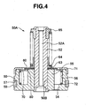
- the front fork 10 is provided with a partition wall member 50 (FIGS. 5A and 5B) constituting a compression side valve unit 50A (FIG. 4) in an upper portion of the hollow pipe 22.
- the partition wall member 50 is mounted to an upper end surface of the expanded portion 31 in the hollow pipe 22, and is held while being pinched with respect to the upper end surface of the expanded portion 31 by the suspension spring 26 mentioned above.
- the partition wall member 50 sections the oil reservoir chamber 28 mentioned above into upper and lower sides.
- a valve guide 52 is provided having a center hole 52A communicating an upper oil reservoir chamber 28A with a lower oil reservoir chamber 28B so as to be fixed to an inserting and attaching hole 50B.
- the partition wall member 50 is provided with an expansion and compression common flow passage 54 communicating the upper and lower oil reservoir chambers 28A and 28B in a periphery of the center hole 52A.
- the expansion and compression common flow passage 54 formed in the partition wall member 50 is provided with an annular deflection valve 60 corresponding to a compression side damper valve, when being supported in an inner periphery, and an annular check valve 70 when supported in an outer periphery.
- An outer periphery of the deflection valve 60 and an inner periphery of the check valve 70 are partially overlapped so as to position the deflection valve 60 in a side of the upper oil reservoir chamber 28A.
- the deflection valve 60 corresponding to a laminated body of a plurality of sheet valves is mounted on an upper end surface of a deflection valve front surface side supporting portion 55 around the inserting and attaching hole 50B of the valve guide 52 in the partition wall member 50 via a thin shim 62 (not shown) having an outer diameter larger than an inner peripheral diameter of the expansion and compression common flow passage 54.
- a first spring 64 is provided in a back surface of the deflection valve 60, in a side of the upper oil reservoir chamber 28A, via a spring receiver 63 having a diameter smaller than the deflection valve 60. In this case, the first spring 64 is supported by a back surface to a spring receiver 65 fixed to an upper end portion of the valve guide 52 in accordance with a caulking process.
- An inner periphery of the deflection valve 60 is provided in an outer periphery of the valve guide 52 in such a manner as to freely move in an axial direction.
- the first spring 64 holds the inner peripheral portion of the deflection valve 60 with respect to the partition wall member 50 so as to support in a back surface.
- the deflection valve 60 is opened when the working fluid in the lower oil reservoir chamber 28B reaches a fixed flow speed.
- a guide hole 56 which can receive the check valve 70 is provided in an upper end portion in an outer peripheral side of the expansion and compression common flow passage 54 in the partition wall member 50.
- An outer periphery of the check valve 70 is slidably fitted to the guide hole 56 so as to freely slide in an axial -direction.
- a valve stopper 71 is fixed to an opening portion of the guide hole 56.
- a second spring 72 is provided on a back surface of the check valve 70, in a side of the lower oil reservoir chamber 28B. The second spring 72 is received in the interior of the guide hole 56 of the partition wall member 50, and holds an outer peripheral portion of the check valve 70 with respect to the valve stopper 71 so as to support a back surface.
- a small gap 80 is provided in the overlapping portion between the deflection valve 60 and the check valve 70.
- the small gap 80 is provided owing to an existence of the shim 62 mentioned above.
- the size of the small gap 80 can be changed by adjusting a thickness of the shim 62.
- annular groove 57 is provided in an outer periphery of the partition wall member 50, and a seal member 58 (FIGS. 6A and 6B) is fitted to the annular groove 57.
- the seal member 58 comprises a C-shaped piston ring having a skewed slit at one position in a peripheral direction, as shown in FIGS. 6A and 6B, and is slidably contacted with an inner periphery of the inner tube 12.
- an upper end surface of the expanded portion 31 of the hollow pipe 22 and a lower end surface of the partition wall member 50 which are in contact with each other both form a flat surface.
- the seal member 58 of the partition wall member 50 is assembled and held in a state of being press inserted to the inner periphery of the inner tube 12 with a fixed fastening margin.
- the partition wall member 50 is prevented from being pushed up from the expanded portion 31 of the hollow pipe 22 so as to be offset therefrom, when the pressure of the upper oil chamber 27A in the outer-side of the hollow pipe 22 ascends during the expansion stroke in the manner mentioned below.
- the fastening margin of the seal member 58 is set such that the sum of the spring force of the suspension spring 26 and the friction force of the seal member 58 with respect to the inner periphery of the inner tube 12 is more than the pushing up force obtained by the maximum hydraulic pressure of the upper oil chamber 27A during the expansion stroke applied to the pressure receiving surface of the seal member 58 through the annular gap between the inner periphery of the inner tube 12 and the outer periphery of the expanded portion 31 of the hollow pipe 22.
- the inner tube 12 descends from an expanded state in FIG. 1 so as to increase pressure in the lower oil chamber 27B.
- the check valve 46 of the piston 41 moves in an upper direction so as to be opened, whereby the oil in the lower oil chamber 27B is replaced by oil from the upper oil chamber 27A.
- the oil in an amount determined by multiplying cross sectional area of the inner tube 12 by a stroke, moves from the lower oil chamber 27B to the lower oil reservoir chamber 28B through the through hole 34.
- a damping force is generated caused by a passage resistance of the center hole 52A and the small gap 80 when the oil in the lower oil reservoir chamber 28B moves to the upper oil reservoir chamber 28A via the center hole 52A of the partition wall member 50, and the small gap 80 of the expansion and compression flow passage 54.
- the magnitude of the damping force can be changed based on a diameter of the center hole 52A and the size of the small gap 80.
- the deflection valve 60 When the piston speed of the front fork 10 is moderate, the deflection valve 60 is opened in accordance with a deflecting deformation based on a deflection property. A damping force is generated caused by the passage resistance of the oil which moves from the lower oil reservoir chamber 28B to the upper oil reservoir chamber 28A through the opening flow passage of the deflection valve 60. The magnitude of the damping force can be changed in accordance with a thickness and a diameter of the deflection valve 60.
- the deflection valve 60 When the piston speed of the front fork 10 is high, the deflection valve 60 is slid in accordance with the deflection of the first spring 64 supporting the deflection valve 60 in the back surface so as to open to a relatively large extent.
- the passage resistance applied to the oil which moves from the lower oil reservoir chamber 28B to the upper oil reservoir chamber 28A is reduced.
- the magnitude of the damping force can be changed based on the spring constant and the set load of the first spring 64. Accordingly, the front fork 10 undergoes a large stroke, and a vibration absorbing property is improved.
- the inner tube 12 ascends from a compressed state so as to increase pressure in the upper oil chamber 27A.
- a damping force is generated caused by a passage resistance generated in the annular gap 48 when the oil in the upper oil chamber 27A moves from the annular gap 48 of the check valve 46 seated on the upper taper portion 45A of the piston 41 to the lower oil chamber 27B.
- a passage resistance is generated in the orifice 35 when the oil in the upper oil chamber 27A comes out of the orifice 35 in the hollow pipe 22 and moves to the lower oil chamber 27B via the lower oil reservoir chamber 28A and the through hole 34 of the hollow pipe 22.
- An embodiment 2 is substantially different from the embodiment 1 in that an annular groove 31A is provided in an outer periphery of the expanded portion 31 in the upper portion of the hollow pipe 22.
- the seal member 32 is fitted to the annular groove 31A.
- the seal member 32 comprises a piston ring, and is slidably contacted with the inner periphery of the inner tube 12.
- the following operations and effects can be achieved in addition to the operations and effects (a), (b) and (d) in the embodiment 1.
- the seal member 32 provided in the upper portion of the hollow pipe 22 block off the increased pressure oil being applied to the side of the partition wall member 50. Accordingly, the partition wall member 50 can be -stably arranged in the upper portion of the hollow pipe 22 without setting the fastening margin of the seal member 58 provided in the partition wall member 50 with respect to the inner periphery of the inner tube 12 too tight.
- the partition wall member 50 and the seal member 58 can be easily assembled in the inner periphery of the inner tube 12.
Landscapes
- Engineering & Computer Science (AREA)
- General Engineering & Computer Science (AREA)
- Mechanical Engineering (AREA)
- Physics & Mathematics (AREA)
- Fluid Mechanics (AREA)
- Fluid-Damping Devices (AREA)
- Axle Suspensions And Sidecars For Cycles (AREA)
Applications Claiming Priority (2)
| Application Number | Priority Date | Filing Date | Title |
|---|---|---|---|
| JP2004007300 | 2004-01-14 | ||
| JP2004007300A JP2005201345A (ja) | 2004-01-14 | 2004-01-14 | 自動二輪車等のフロントフォーク |
Publications (2)
| Publication Number | Publication Date |
|---|---|
| EP1555199A1 true EP1555199A1 (de) | 2005-07-20 |
| EP1555199B1 EP1555199B1 (de) | 2006-12-27 |
Family
ID=34616874
Family Applications (1)
| Application Number | Title | Priority Date | Filing Date |
|---|---|---|---|
| EP04019089A Expired - Fee Related EP1555199B1 (de) | 2004-01-14 | 2004-08-11 | Motorradvorderradgabel |
Country Status (4)
| Country | Link |
|---|---|
| US (1) | US7296812B2 (de) |
| EP (1) | EP1555199B1 (de) |
| JP (1) | JP2005201345A (de) |
| DE (1) | DE602004003893T2 (de) |
Cited By (1)
| Publication number | Priority date | Publication date | Assignee | Title |
|---|---|---|---|---|
| EP2233777A1 (de) * | 2009-03-23 | 2010-09-29 | Honda Motor Co., Ltd. | Hydraulischer Stoßdämpfer |
Families Citing this family (9)
| Publication number | Priority date | Publication date | Assignee | Title |
|---|---|---|---|---|
| TWM274311U (en) * | 2005-03-15 | 2005-09-01 | Spinner Industry Co Ltd | Damper for front fork of bicycle |
| US7516969B2 (en) * | 2005-10-25 | 2009-04-14 | Hui-Hsiung Chen | Travel adjustable front suspension fork |
| JP4898386B2 (ja) * | 2006-10-27 | 2012-03-14 | カヤバ工業株式会社 | フロントフォーク |
| JP2009008152A (ja) * | 2007-06-27 | 2009-01-15 | Showa Corp | 油圧緩衝器 |
| IT1394086B1 (it) * | 2009-04-16 | 2012-05-25 | Casa Dell Ammortizzatore Bitubo Di Mardollo Scipione & C S N C Con Sigla C D A Bitubo Di Mardollo Sc | Dispositivo di smorzamento di vibrazioni, particolarmente per ammortizzatori idraulici per veicoli |
| US8701846B2 (en) * | 2009-08-26 | 2014-04-22 | Tenneco Automotive Operating Company Inc | Inverted strut comprising an air damper combined with a hydraulic stop |
| US8800973B2 (en) | 2011-02-25 | 2014-08-12 | Fox Factory, Incorporated | Compression sensitive suspension dampening |
| JP5873666B2 (ja) * | 2011-08-30 | 2016-03-01 | 株式会社ショーワ | フロントフォーク |
| JP6357067B2 (ja) * | 2014-10-01 | 2018-07-11 | Kybモーターサイクルサスペンション株式会社 | フロントフォーク |
Citations (3)
| Publication number | Priority date | Publication date | Assignee | Title |
|---|---|---|---|---|
| JPS62125971A (ja) * | 1985-11-28 | 1987-06-08 | ヤマハ発動機株式会社 | 自動二輪車のフロントフオ−ク |
| JPH1061704A (ja) * | 1996-08-26 | 1998-03-06 | Kayaba Ind Co Ltd | フロントフォーク |
| JP2003232395A (ja) * | 2002-02-07 | 2003-08-22 | Showa Corp | 自動二輪車等のフロントフォーク |
Family Cites Families (12)
| Publication number | Priority date | Publication date | Assignee | Title |
|---|---|---|---|---|
| AU553238B2 (en) * | 1983-09-26 | 1986-07-10 | Nhk Spring Co. Ltd. | Vehicle hydropneumatic suspension |
| JPS60157496A (ja) * | 1983-12-27 | 1985-08-17 | 日本トング株式会社 | ロ−ルリフタ− |
| US5009451A (en) * | 1988-07-19 | 1991-04-23 | Kabushiki Kaisha Showa Seisakusho | Shock absorber for use in a vehicle |
| IT1234608B (it) * | 1989-03-13 | 1992-05-25 | Lifter Srl | Colonna di supporto oleopneumatica regolabile, ammortizzata. |
| US5494302A (en) * | 1991-06-11 | 1996-02-27 | Cannondale Corporation | Suspension assembly for a vehicle |
| JP3370130B2 (ja) * | 1993-03-18 | 2003-01-27 | 株式会社ショーワ | 自転車用前輪懸架装置 |
| ES1029231Y (es) * | 1994-10-18 | 1995-11-01 | Pariente Antonio Cabrerizo | Horquilla de bicicleta amortiguada. |
| US6568664B2 (en) * | 1998-11-11 | 2003-05-27 | Kayaba Kogyo Kabushiki Kaisha | Front fork for motorcycle |
| JP2002139089A (ja) * | 2000-11-06 | 2002-05-17 | Kayaba Ind Co Ltd | フロントフォーク |
| JP4637409B2 (ja) * | 2001-06-28 | 2011-02-23 | カヤバ工業株式会社 | フロントフォーク |
| JP4341830B2 (ja) * | 2003-12-16 | 2009-10-14 | 株式会社ショーワ | 自動二輪車等のフロントフォーク |
| US7290643B2 (en) * | 2003-12-17 | 2007-11-06 | Nobuaki Fujita | Front fork in two-wheeled motor vehicle or the like |
-
2004
- 2004-01-14 JP JP2004007300A patent/JP2005201345A/ja active Pending
- 2004-08-11 DE DE602004003893T patent/DE602004003893T2/de active Active
- 2004-08-11 EP EP04019089A patent/EP1555199B1/de not_active Expired - Fee Related
- 2004-08-25 US US10/925,706 patent/US7296812B2/en not_active Expired - Fee Related
Patent Citations (3)
| Publication number | Priority date | Publication date | Assignee | Title |
|---|---|---|---|---|
| JPS62125971A (ja) * | 1985-11-28 | 1987-06-08 | ヤマハ発動機株式会社 | 自動二輪車のフロントフオ−ク |
| JPH1061704A (ja) * | 1996-08-26 | 1998-03-06 | Kayaba Ind Co Ltd | フロントフォーク |
| JP2003232395A (ja) * | 2002-02-07 | 2003-08-22 | Showa Corp | 自動二輪車等のフロントフォーク |
Non-Patent Citations (2)
| Title |
|---|
| PATENT ABSTRACTS OF JAPAN vol. 1998, no. 08 30 June 1998 (1998-06-30) * |
| PATENT ABSTRACTS OF JAPAN vol. 2003, no. 12 5 December 2003 (2003-12-05) * |
Cited By (1)
| Publication number | Priority date | Publication date | Assignee | Title |
|---|---|---|---|---|
| EP2233777A1 (de) * | 2009-03-23 | 2010-09-29 | Honda Motor Co., Ltd. | Hydraulischer Stoßdämpfer |
Also Published As
| Publication number | Publication date |
|---|---|
| JP2005201345A (ja) | 2005-07-28 |
| DE602004003893T2 (de) | 2007-04-12 |
| EP1555199B1 (de) | 2006-12-27 |
| DE602004003893D1 (de) | 2007-02-08 |
| US20050151343A1 (en) | 2005-07-14 |
| US7296812B2 (en) | 2007-11-20 |
Similar Documents
| Publication | Publication Date | Title |
|---|---|---|
| EP1947362B1 (de) | Hydraulischer einzelzylinder-stossdämpfer für ein fahrzeug | |
| JP2517808Y2 (ja) | 複筒式液圧緩衝器のロッドガイド | |
| EP1826453A1 (de) | Einrichtung für Vorderradgabel zur Regelung der Dämpfkraft | |
| EP2009319A2 (de) | Stoßdämpfer | |
| US20070051574A1 (en) | Rod guide seal | |
| US11181161B2 (en) | Shock absorber base valve assembly | |
| WO2015178285A1 (ja) | 緩衝器 | |
| US7290643B2 (en) | Front fork in two-wheeled motor vehicle or the like | |
| EP1555199B1 (de) | Motorradvorderradgabel | |
| WO2015178287A1 (ja) | 緩衝器 | |
| WO2018163868A1 (ja) | 緩衝器 | |
| US20080053764A1 (en) | Front fork | |
| CN104603495A (zh) | 多级可调谐递减阀 | |
| GB2417541A (en) | Base cup connection for shock absorber | |
| JP4902497B2 (ja) | 油圧緩衝器 | |
| JPH1182590A (ja) | 油圧緩衝器 | |
| JPH07238973A (ja) | 油圧緩衝器 | |
| US20030178268A1 (en) | Suspension damper mounting ring casting with steel insert | |
| CN109983250B (zh) | 减震器 | |
| JP4107850B2 (ja) | 自動二輪車のフロントフォーク | |
| US20240102530A1 (en) | Shock absorber | |
| CN220726961U (zh) | 一种双向筒式减振器下限位缓冲结构 | |
| JPH031536B2 (de) | ||
| US20240102528A1 (en) | Shock absorber and manufacturing method of shock absorber | |
| JP6916757B2 (ja) | フロントフォーク |
Legal Events
| Date | Code | Title | Description |
|---|---|---|---|
| PUAI | Public reference made under article 153(3) epc to a published international application that has entered the european phase |
Free format text: ORIGINAL CODE: 0009012 |
|
| AK | Designated contracting states |
Kind code of ref document: A1 Designated state(s): AT BE BG CH CY CZ DE DK EE ES FI FR GB GR HU IE IT LI LU MC NL PL PT RO SE SI SK TR |
|
| AX | Request for extension of the european patent |
Extension state: AL HR LT LV MK |
|
| 17P | Request for examination filed |
Effective date: 20051108 |
|
| AKX | Designation fees paid |
Designated state(s): DE GB IT |
|
| GRAP | Despatch of communication of intention to grant a patent |
Free format text: ORIGINAL CODE: EPIDOSNIGR1 |
|
| GRAS | Grant fee paid |
Free format text: ORIGINAL CODE: EPIDOSNIGR3 |
|
| GRAA | (expected) grant |
Free format text: ORIGINAL CODE: 0009210 |
|
| AK | Designated contracting states |
Kind code of ref document: B1 Designated state(s): DE GB IT |
|
| REG | Reference to a national code |
Ref country code: GB Ref legal event code: FG4D |
|
| REF | Corresponds to: |
Ref document number: 602004003893 Country of ref document: DE Date of ref document: 20070208 Kind code of ref document: P |
|
| PLBE | No opposition filed within time limit |
Free format text: ORIGINAL CODE: 0009261 |
|
| STAA | Information on the status of an ep patent application or granted ep patent |
Free format text: STATUS: NO OPPOSITION FILED WITHIN TIME LIMIT |
|
| 26N | No opposition filed |
Effective date: 20070928 |
|
| PGFP | Annual fee paid to national office [announced via postgrant information from national office to epo] |
Ref country code: DE Payment date: 20100812 Year of fee payment: 7 Ref country code: IT Payment date: 20100817 Year of fee payment: 7 |
|
| PGFP | Annual fee paid to national office [announced via postgrant information from national office to epo] |
Ref country code: GB Payment date: 20100811 Year of fee payment: 7 |
|
| GBPC | Gb: european patent ceased through non-payment of renewal fee |
Effective date: 20110811 |
|
| PG25 | Lapsed in a contracting state [announced via postgrant information from national office to epo] |
Ref country code: IT Free format text: LAPSE BECAUSE OF NON-PAYMENT OF DUE FEES Effective date: 20110811 |
|
| REG | Reference to a national code |
Ref country code: DE Ref legal event code: R119 Ref document number: 602004003893 Country of ref document: DE Effective date: 20120301 |
|
| PG25 | Lapsed in a contracting state [announced via postgrant information from national office to epo] |
Ref country code: GB Free format text: LAPSE BECAUSE OF NON-PAYMENT OF DUE FEES Effective date: 20110811 |
|
| PG25 | Lapsed in a contracting state [announced via postgrant information from national office to epo] |
Ref country code: DE Free format text: LAPSE BECAUSE OF NON-PAYMENT OF DUE FEES Effective date: 20120301 |