EP1555003A1 - Sesselartige Massagevorrichtung - Google Patents
Sesselartige Massagevorrichtung Download PDFInfo
- Publication number
- EP1555003A1 EP1555003A1 EP04030737A EP04030737A EP1555003A1 EP 1555003 A1 EP1555003 A1 EP 1555003A1 EP 04030737 A EP04030737 A EP 04030737A EP 04030737 A EP04030737 A EP 04030737A EP 1555003 A1 EP1555003 A1 EP 1555003A1
- Authority
- EP
- European Patent Office
- Prior art keywords
- chair
- leg
- leg massage
- parts
- massaging machine
- Prior art date
- Legal status (The legal status is an assumption and is not a legal conclusion. Google has not performed a legal analysis and makes no representation as to the accuracy of the status listed.)
- Withdrawn
Links
- 210000001699 lower leg Anatomy 0.000 claims abstract description 220
- 238000000034 method Methods 0.000 description 3
- 210000003127 knee Anatomy 0.000 description 2
- 208000004067 Flatfoot Diseases 0.000 description 1
- 230000005489 elastic deformation Effects 0.000 description 1
- 230000005764 inhibitory process Effects 0.000 description 1
- 210000002414 leg Anatomy 0.000 description 1
- 238000003825 pressing Methods 0.000 description 1
- 210000000689 upper leg Anatomy 0.000 description 1
Images






Classifications
-
- H—ELECTRICITY
- H05—ELECTRIC TECHNIQUES NOT OTHERWISE PROVIDED FOR
- H05B—ELECTRIC HEATING; ELECTRIC LIGHT SOURCES NOT OTHERWISE PROVIDED FOR; CIRCUIT ARRANGEMENTS FOR ELECTRIC LIGHT SOURCES, IN GENERAL
- H05B41/00—Circuit arrangements or apparatus for igniting or operating discharge lamps
- H05B41/14—Circuit arrangements
- H05B41/26—Circuit arrangements in which the lamp is fed by power derived from DC by means of a converter, e.g. by high-voltage DC
- H05B41/28—Circuit arrangements in which the lamp is fed by power derived from DC by means of a converter, e.g. by high-voltage DC using static converters
- H05B41/282—Circuit arrangements in which the lamp is fed by power derived from DC by means of a converter, e.g. by high-voltage DC using static converters with semiconductor devices
-
- A—HUMAN NECESSITIES
- A61—MEDICAL OR VETERINARY SCIENCE; HYGIENE
- A61H—PHYSICAL THERAPY APPARATUS, e.g. DEVICES FOR LOCATING OR STIMULATING REFLEX POINTS IN THE BODY; ARTIFICIAL RESPIRATION; MASSAGE; BATHING DEVICES FOR SPECIAL THERAPEUTIC OR HYGIENIC PURPOSES OR SPECIFIC PARTS OF THE BODY
- A61H37/00—Accessories for massage
-
- A—HUMAN NECESSITIES
- A61—MEDICAL OR VETERINARY SCIENCE; HYGIENE
- A61H—PHYSICAL THERAPY APPARATUS, e.g. DEVICES FOR LOCATING OR STIMULATING REFLEX POINTS IN THE BODY; ARTIFICIAL RESPIRATION; MASSAGE; BATHING DEVICES FOR SPECIAL THERAPEUTIC OR HYGIENIC PURPOSES OR SPECIFIC PARTS OF THE BODY
- A61H9/00—Pneumatic or hydraulic massage
- A61H9/005—Pneumatic massage
-
- G—PHYSICS
- G02—OPTICS
- G02F—OPTICAL DEVICES OR ARRANGEMENTS FOR THE CONTROL OF LIGHT BY MODIFICATION OF THE OPTICAL PROPERTIES OF THE MEDIA OF THE ELEMENTS INVOLVED THEREIN; NON-LINEAR OPTICS; FREQUENCY-CHANGING OF LIGHT; OPTICAL LOGIC ELEMENTS; OPTICAL ANALOGUE/DIGITAL CONVERTERS
- G02F1/00—Devices or arrangements for the control of the intensity, colour, phase, polarisation or direction of light arriving from an independent light source, e.g. switching, gating or modulating; Non-linear optics
- G02F1/01—Devices or arrangements for the control of the intensity, colour, phase, polarisation or direction of light arriving from an independent light source, e.g. switching, gating or modulating; Non-linear optics for the control of the intensity, phase, polarisation or colour
- G02F1/13—Devices or arrangements for the control of the intensity, colour, phase, polarisation or direction of light arriving from an independent light source, e.g. switching, gating or modulating; Non-linear optics for the control of the intensity, phase, polarisation or colour based on liquid crystals, e.g. single liquid crystal display cells
- G02F1/133—Constructional arrangements; Operation of liquid crystal cells; Circuit arrangements
- G02F1/1333—Constructional arrangements; Manufacturing methods
- G02F1/1335—Structural association of cells with optical devices, e.g. polarisers or reflectors
- G02F1/1336—Illuminating devices
-
- H—ELECTRICITY
- H05—ELECTRIC TECHNIQUES NOT OTHERWISE PROVIDED FOR
- H05B—ELECTRIC HEATING; ELECTRIC LIGHT SOURCES NOT OTHERWISE PROVIDED FOR; CIRCUIT ARRANGEMENTS FOR ELECTRIC LIGHT SOURCES, IN GENERAL
- H05B41/00—Circuit arrangements or apparatus for igniting or operating discharge lamps
- H05B41/14—Circuit arrangements
- H05B41/26—Circuit arrangements in which the lamp is fed by power derived from DC by means of a converter, e.g. by high-voltage DC
- H05B41/28—Circuit arrangements in which the lamp is fed by power derived from DC by means of a converter, e.g. by high-voltage DC using static converters
- H05B41/288—Circuit arrangements in which the lamp is fed by power derived from DC by means of a converter, e.g. by high-voltage DC using static converters with semiconductor devices and specially adapted for lamps without preheating electrodes, e.g. for high-intensity discharge lamps, high-pressure mercury or sodium lamps or low-pressure sodium lamps
-
- A—HUMAN NECESSITIES
- A61—MEDICAL OR VETERINARY SCIENCE; HYGIENE
- A61H—PHYSICAL THERAPY APPARATUS, e.g. DEVICES FOR LOCATING OR STIMULATING REFLEX POINTS IN THE BODY; ARTIFICIAL RESPIRATION; MASSAGE; BATHING DEVICES FOR SPECIAL THERAPEUTIC OR HYGIENIC PURPOSES OR SPECIFIC PARTS OF THE BODY
- A61H2201/00—Characteristics of apparatus not provided for in the preceding codes
- A61H2201/01—Constructive details
- A61H2201/0119—Support for the device
- A61H2201/0138—Support for the device incorporated in furniture
- A61H2201/0149—Seat or chair
-
- A—HUMAN NECESSITIES
- A61—MEDICAL OR VETERINARY SCIENCE; HYGIENE
- A61H—PHYSICAL THERAPY APPARATUS, e.g. DEVICES FOR LOCATING OR STIMULATING REFLEX POINTS IN THE BODY; ARTIFICIAL RESPIRATION; MASSAGE; BATHING DEVICES FOR SPECIAL THERAPEUTIC OR HYGIENIC PURPOSES OR SPECIFIC PARTS OF THE BODY
- A61H2201/00—Characteristics of apparatus not provided for in the preceding codes
- A61H2201/12—Driving means
- A61H2201/1207—Driving means with electric or magnetic drive
- A61H2201/1215—Rotary drive
-
- A—HUMAN NECESSITIES
- A61—MEDICAL OR VETERINARY SCIENCE; HYGIENE
- A61H—PHYSICAL THERAPY APPARATUS, e.g. DEVICES FOR LOCATING OR STIMULATING REFLEX POINTS IN THE BODY; ARTIFICIAL RESPIRATION; MASSAGE; BATHING DEVICES FOR SPECIAL THERAPEUTIC OR HYGIENIC PURPOSES OR SPECIFIC PARTS OF THE BODY
- A61H2201/00—Characteristics of apparatus not provided for in the preceding codes
- A61H2201/14—Special force transmission means, i.e. between the driving means and the interface with the user
-
- A—HUMAN NECESSITIES
- A61—MEDICAL OR VETERINARY SCIENCE; HYGIENE
- A61H—PHYSICAL THERAPY APPARATUS, e.g. DEVICES FOR LOCATING OR STIMULATING REFLEX POINTS IN THE BODY; ARTIFICIAL RESPIRATION; MASSAGE; BATHING DEVICES FOR SPECIAL THERAPEUTIC OR HYGIENIC PURPOSES OR SPECIFIC PARTS OF THE BODY
- A61H2201/00—Characteristics of apparatus not provided for in the preceding codes
- A61H2201/16—Physical interface with patient
- A61H2201/1602—Physical interface with patient kind of interface, e.g. head rest, knee support or lumbar support
- A61H2201/164—Feet or leg, e.g. pedal
-
- A—HUMAN NECESSITIES
- A61—MEDICAL OR VETERINARY SCIENCE; HYGIENE
- A61H—PHYSICAL THERAPY APPARATUS, e.g. DEVICES FOR LOCATING OR STIMULATING REFLEX POINTS IN THE BODY; ARTIFICIAL RESPIRATION; MASSAGE; BATHING DEVICES FOR SPECIAL THERAPEUTIC OR HYGIENIC PURPOSES OR SPECIFIC PARTS OF THE BODY
- A61H2201/00—Characteristics of apparatus not provided for in the preceding codes
- A61H2201/16—Physical interface with patient
- A61H2201/1657—Movement of interface, i.e. force application means
- A61H2201/1671—Movement of interface, i.e. force application means rotational
-
- A—HUMAN NECESSITIES
- A61—MEDICAL OR VETERINARY SCIENCE; HYGIENE
- A61H—PHYSICAL THERAPY APPARATUS, e.g. DEVICES FOR LOCATING OR STIMULATING REFLEX POINTS IN THE BODY; ARTIFICIAL RESPIRATION; MASSAGE; BATHING DEVICES FOR SPECIAL THERAPEUTIC OR HYGIENIC PURPOSES OR SPECIFIC PARTS OF THE BODY
- A61H2203/00—Additional characteristics concerning the patient
- A61H2203/04—Position of the patient
- A61H2203/0425—Sitting on the buttocks
- A61H2203/0431—Sitting on the buttocks in 90°/90°-position, like on a chair
-
- A—HUMAN NECESSITIES
- A61—MEDICAL OR VETERINARY SCIENCE; HYGIENE
- A61H—PHYSICAL THERAPY APPARATUS, e.g. DEVICES FOR LOCATING OR STIMULATING REFLEX POINTS IN THE BODY; ARTIFICIAL RESPIRATION; MASSAGE; BATHING DEVICES FOR SPECIAL THERAPEUTIC OR HYGIENIC PURPOSES OR SPECIFIC PARTS OF THE BODY
- A61H2203/00—Additional characteristics concerning the patient
- A61H2203/04—Position of the patient
- A61H2203/0425—Sitting on the buttocks
- A61H2203/0437—Sitting on the buttocks with stretched legs, like in a bed
-
- A—HUMAN NECESSITIES
- A61—MEDICAL OR VETERINARY SCIENCE; HYGIENE
- A61H—PHYSICAL THERAPY APPARATUS, e.g. DEVICES FOR LOCATING OR STIMULATING REFLEX POINTS IN THE BODY; ARTIFICIAL RESPIRATION; MASSAGE; BATHING DEVICES FOR SPECIAL THERAPEUTIC OR HYGIENIC PURPOSES OR SPECIFIC PARTS OF THE BODY
- A61H2205/00—Devices for specific parts of the body
- A61H2205/10—Leg
-
- A—HUMAN NECESSITIES
- A61—MEDICAL OR VETERINARY SCIENCE; HYGIENE
- A61H—PHYSICAL THERAPY APPARATUS, e.g. DEVICES FOR LOCATING OR STIMULATING REFLEX POINTS IN THE BODY; ARTIFICIAL RESPIRATION; MASSAGE; BATHING DEVICES FOR SPECIAL THERAPEUTIC OR HYGIENIC PURPOSES OR SPECIFIC PARTS OF THE BODY
- A61H2205/00—Devices for specific parts of the body
- A61H2205/10—Leg
- A61H2205/106—Leg for the lower legs
Definitions
- the present invention relates to a Chair-type massaging machine having a lower-leg massage function.
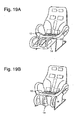
- Fig. 19 shows an external view of a first conventional massage chair.
- the massage chair is equipped with a lower-leg supporting part 14 in concavo-convex form having a massage function, rotatably around a pivot 16 as a Rotational axis, being mounted on the front end of a seat part 12.
- the lower-leg supporting part 14 is forwardly rotated and the user then places his or her lower-legs on the concave parts of the lower-leg supporting part 14, as shown in Fig. 19A.
- the lower-leg supporting part 14 is rotated downward, as shown in Fig. 19B.
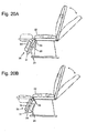
- chair-type massaging machines in which the rear surface of the lower-leg supporting part for supporting lower-legs has been formed flat, and when the lower-leg massage function is not in use, the lower-leg supporting part can be inverted in a forward/backward direction around a horizontal axis 26 as a primary axis (e.g. Japanese Patent Laid-Open No. 2003-62024).
- Fig. 20 is one example of the chair-type massaging machine as thus described; A shows a state where the lower-leg massage function is usable, and B shows a case where the lower-leg massage function is not in use. Further, Fig. 21 is one example of the switching of a footrest 25 for supporting lower-legs; A shows a state where a massaging surface 24 for applying massage to lower-legs is usable, and B shows a state where a flat foot placing surface 35 is usable when lower-leg massage is not applied.
- the conventional chair-type massaging machine having the lower-leg massage function since the provided footrest 25 is invertible in the forward/backward direction against the horizontal primary axis 26, it has been necessary to form a frame outside the footrest 25 for supporting the rotational axis. Therefore, the conventional chair-type massaging machine having the lower-leg massage function has a problem of the increased total weight thereof. Further, in this chair-type massaging machine, the mobile part of the footrest 25 and the frame supporting the footrest 25 are exposed to the outside, thus creating the possibility that the user's toe could be caught between the lower-leg massager part and the frame. Moreover, in this chair-type massaging machine, the shape of the lower-leg massager part is not accommodated with good appearance in the overall shape of the chair-type massaging machine, thereby setting a limit on the design of the chair-type massaging machine.
- the present invention was made in light of the above actual situations, and has an object to provide a technique to be used in a massaging machine having a lower-leg massage function, for simplifying components of the lower-leg massage function while improving the user's comfort when the lower-leg massage function is not in use.
- the present invention was configured as follows in order to achieve the above object.
- the present invention can be specified as a chair-type massaging machine comprising: a seat part on which a user is seated; a rotational axis, extended out forward from said front end of said seat part; and a lower-leg massage part which has first surfaces in concavo-convex form including concave parts and convex parts, and a second surface in almost flat form, and in which the first surfaces and the second surface are engaged with each other invertibly around the rotational axis.
- the Lower-leg massage part rotates around the rotational axis extended out forward from the front end of the seat part, in the switching between the first surfaces for applying lower-leg massage and the second surface formed in almost flat for supporting lower-legs.
- the present invention it is possible to provide a technique to be used in a massaging machine having a lower-leg massage function, for simplifying components of the lower-leg massage function while improving the user's comfort when the lower-leg massage function is not in use.
- first surfaces and the second surface may be formed on the rear surface sides of each other.
- the present invention can also be specified as a chair-type massaging machine comprising: a seat part on which a user is seated; a pair of rotational axes, each extended out forward from the front end of said seat part; and a pair of lower-leg massage parts, each of which has a first surface in concavo-convex form including a concave part and convex parts, and a second surface in almost flat form, and in which the first surface and the second surface are engaged with each other rotatably around said rotational axis.
- the lower-leg massage parts each formed to enable switching between the first surface for applying lower-leg massage and the second surface formed in almost flat for supporting lower-legs, were provided so as to respectively accommodate a pair of lower-legs. Further, in the present invention, the pair of lower-leg massage parts was rotated by respectively corresponding axes. With this configuration, the lower-leg massage parts rotate with a small rotation radius in the present invention.
- said concave part may be formed of a bottom wall for supporting a lower-leg, and a pair of sidewalls erected on both sides of said bottom wall along a lower-leg to be messaged, to constitute the convex part, said rotational axis may be positioned close to the outside surface of said bottom wall in the central vertical section of the bottom wall, and said first surfaces and the second surface may be formed on the rear surface sides of each other.
- said concave part may be formed of a bottom wall for supporting a lower-leg, and an outside wall in contact with said lower-leg from the outside and an inside wall in contact with said lower-leg from the inside, which are erected on each side of said bottom wall along the lower-leg to be messaged, to constitute said convex part, said rotational axis may be positioned in the vicinity of a ridge constructed of the rear surface of said bottom wall and the rear surface of said outside wall, said inside wall is formed lower than said outside wall, and said second surface may be formed on the outside of said outside wall.
- said concave part may be formed of a bottom wall for supporting a lower-leg, and an outer sidewall in contact with said lower-leg from the outside and an inner sidewall in contact with said lower-leg from the inside, which are erected on each side of said bottom wall along the lower-leg to be messaged, to constitute said convex part, and said rotational axis may be positioned in the vicinity of a ridge constructed of the rear surface of said bottom wall and the rear surface of said inner sidewall.
- Figs. 1 and 2 are views of a chair-type massaging machine 100 having a lower-leg massage function according to Embodiment 1 of the present invention; Fig. 1 shows a state where a lower-leg massage part is usable, and Fig. 2 shows a state where the lower-leg massage part is not in use.
- the chair-type massaging machine 100 has a chair body 110 provided with a seat part 111 on which a user is seated, and a backrest part 112 for supporting the user's upper-body when the user is seated.
- the chair-type massaging machine 100 further has a lower-leg massage part 120 that is provided with concave parts 121 and 122 and applies massage to lower-legs supported by those concave parts 121 and 122.
- the lower-leg massage part 120 is mounted on the front end of the seat part 111.
- the lower-leg massage part 120 is engaged with the chair body 110 at the rotation center T1 provided at the approximate center of the cross section of the lower-leg massage part 120, by a rotational axis 138 extended out forward from the front end of the seat part 111.
- This rotational axis 138 serves for rotating the lower-leg massage part 120 around the rotation center T1.
- the concave parts 121 and 122 are formed of a center wall 124A, positioned in the approximate middle in the cross section of the lower-leg massage part 120, and sidewalls 124B and 124C which are both sides of the lower-leg massage part 120.
- the upward-facing top of each of the center wall 124A and the sidewalls 124B and 124C is formed almost flat.
- the bottom walls 121a and 122a of the concave parts 121 and 122 are held wide enough to accommodate the lower-legs (e.g. the lower part than the knee) of the user.
- the insides of the bottom walls 121a and 122a, the center wall 124A, and the inside of the sidewalls 124B and 124C are provided, as appropriate, with massage means (can be considered as a pneumatic or mechanical pressing means, for example), not shown in the figure, for applying massage to the lower-legs accommodated in the concave parts 121 and 122.
- massage means can be considered as a pneumatic or mechanical pressing means, for example
- the concave parts 121 and 122 are facing upward (the position where the concave parts 121 and 122 are in a state of being capable of accommodating the lower-legs of the user seated on the seat part 111)
- massage can be applied to the user's lower-legs by the massage means.
- the surfaces provided with the concave parts 121 and 122 correspond to the first surfaces of the present invention.
- a drive 130 for rotating the lower-leg massage part 120 comprises a motor 131, a drive pulley 132, a drive belt 133, a driven pulley 134, a worm shaft 135, a worm 136, a worm wheel 137 and the rotational axis 138.
- the drive pulley 132 is attached to the top of an output shaft 131a of the motor 131.
- the drive belt 133 running between the drive pulley 132 and the driven pulley 134, the power of the motor 131 is transmitted from the drive pulley 132 to the driven pulley 134.
- the worm 136 is mounted on the worm shaft 135 with the driven pulley 134 attached thereto. This worm 136 transmits the power of the motor 131 to the worm wheel 137 in engagement with the worm 136.
- the rotational axis 138 for rotating the lower-leg massage part 120 is incorporated into the worm wheel 137. By rotation of the rotational axis 138, the lower-leg massage part 120 is rotated around the rotation center T1, for example in the direction of the arrow A.
- the lower-leg massage part 120 is rotated by the drive 130 around the rotation center T1, for example in the direction of the arrow A. With this rotational movement, a foot placing part 125 of the lower-leg massage part 120, formed in almost flat, faces upward (the position where the user, seated on the seat part 111, can place his or her lower-legs). Namely, in the lower-leg massage part 120, the foot placing part 125 and the first surfaces including the concave parts 121 and 122 are provided on the rear surface sides of each other. It should be noted that in the chair-type massaging machine 100 according to the present embodiment, the surface provided with the foot placing part 125 corresponds to the second surface of the present invention.
- the foot placing part 125 Since the foot placing part 125 is facing upward, the user can have his or her lower-legs comfortably supported thereon without a feeling of restraint even when the lower-leg massage part 120 applies no massage to the lower-legs.
- the chair-type massaging machine 100 having the lower-leg massage function according to Embodiment 1 includes the lower-leg massage part 120 that comprises the first surfaces having the massage means for applying massage to the user's lower-legs, and the second surface including the foot placing part 125 in almost flat form capable of supporting the user's lower-legs when no massage is applied to the user's lower-legs. Further, the chair-type massaging machine 100 is formed such that the first surfaces are placed on the opposite side of the second surface (the first surfaces and the second surface are formed on the rear surface sides of each other).
- the rotational axis 138 extended out forward from the front end of the seat part 111 of the chair body 110, supports the lower-leg massage part 120. That is, the chair body 110 is equipped with the lower-leg massage part 120 by the rotational axis 138.
- the lower-leg massage part 120 rotates around the rotational axis 138 as the rotation center T1, to switch between the above first surfaces and second surface.
- the chair-type massaging machine having the lower-leg massage function of Embodiment 1 it is possible to provide, with the simplified configuration, the function of comfortably supporting the user's lower-legs while the user has no feeling of restraint when the lower-leg massage function is not in use.
- Embodiment 2 a chair-type massaging machine having a lower-leg massage function according to Embodiment 2 is described with reference to the drawings. It is to be noted that, when the same component as that used in Embodiment 1 is present in Embodiment 2, the common numeral for that component is used and explanation of the component is not described.
- Figs. 3 and 4 are views of a chair-type massaging machine 200 having a lower-leg massage function according to Embodiment 2; Fig. 3 shows a state where lower-leg massage parts are usable, and Fig. 4 shows a state where the lower-leg massage parts are not in use.
- lower-leg massage parts 220A and 220B are formed so as to be capable of respectively accommodating each one of the user's lower-legs.
- the lower-leg massage parts 220A and 220B respectively have the concave parts 221 and 222, each being capable of accommodating each one of the user's pair lower-legs.
- bottom walls 221a and 222a are held wide enough to respectively accommodate the user's pair of lower-legs (e.g. the part from around the thigh to around the knee), and the concave parts 221 and 222, including on both sides thereof a pair of Sidewalls 224A and 224B with almost flat tops, are formed on the upper surface side in Fig. 3.
- massage means for applying massage to the lower-legs accommodated in the concave parts 221 and 222 which is not shown in the figure, is provided, as appropriate, on the sidewalls 224A and 224B, and the insides of the bottom walls 221a and 222a in the concave parts 221 and 222.
- the concave parts 221 and 222 are facing upward, massage can be applied to the user's lower-legs by the massage means.
- rotation centers T2 and T3 are provided between the middle part of the bottom walls 221a and 222a on the bottoms of the lower-leg massage parts 220A and 220B, and foot placing parts 225A and 225B positioned on the rear surfaces of the bottom walls 221a and 222a.
- the lower-leg massage parts 220A and 220B are engaged with the chair body 110 by a pair of rotational axes 238A and 238B, which are extended out forward from the front end of the seat part 111.
- the rotational axes 238A and 238B serve for rotating the lower-leg massage parts 220A and 220B around the rotation centers T2 and T3.
- the rotation radius of each of those lower-leg massage parts in the chair-type massaging machine 200 is small as compared to that of the lower-leg massage part 120 in the chair-type massaging machine 100.
- Fig. 22 is a view showing radii of rotations of the lower-leg massage parts 220A and 220B around the rotation centers T2 and T3 in the chair-type massaging machine 200.
- the rotation centers T2 and T3 are positioned horizontally in the middle part, and also positioned longitudinally close to the foot placing parts 225A and 225B on the outside surfaces of the lower-leg massage parts 220A and 220B (in Fig. 22, slightly downward from the center of the cross section).
- a rotation radius d1 of each of the lower-leg massage parts 220A and 220B is half of the width 11 of each of the bottom walls 221a and 222a.
- the rotation centers T2 and T3 have been provided in the foregoing position in order to reduce elastic deformation which occurs in the rotation due to the contact between the pair of lower-leg massage parts 220A and 220B.
- the lower-leg massage parts 220A and 220B rotate in the directions of the arrows B1 and B2 (the Lower-leg massage parts 220A and 220B both rotate outwardly) around the rotation centers T2 and T3, to switch from a state where the concave parts 221 and 222 (first surfaces) are facing upward to a state where the foot placing parts 225A and 225B (second surfaces) are facing upward.
- the mutual outward rotation thus described permits the inner sidewalls 224A and 224B of the lower-leg massage parts 220A and 220B to rotate in the direction separating from each other, without coming into contact with each other. Since the foot placing parts 225A and 225B are facing upward, the user can have his or her legs comfortably supported thereon without a feeling of restraint when the lower-leg massage parts 220A and 220B apply no massage to the lower-legs.
- a drive 230 for rotating the lower-leg massage parts 220A and 220B comprises the motor 131, the drive pulley 132, the drive belt 133, the driven pulley 134, a worm shaft 235, worms 236A and 236B, worm wheels 237A and 237B and rotational axes 238A and 238B.
- the difference between the drive 230 and the drive 130 according to Embodiment 1 lies in that, in place of one rotational axis 138 for rotating the lower-leg massage part 120, the rotational axes 238A and 238B are driven for rotating the lower-leg massage parts 220A and 220B which correspond to a pair of lower-legs.
- the total length of the worm shaft 135 is extended to the total length of the worm shaft 235, which is provided with the worms 236A and 236B to be driven so as to rotate the pair of rotational axes 238A and 238B in mutually reverse directions.
- the chair-type massaging machine 200 having the lower-leg massage function according to Embodiment 2 includes the lower-leg massage parts 220A and 220B which are capable of respectively accommodating the user's pair of lower-legs.
- the lower-leg massage parts 220A and 220B comprise the first surfaces including the lower-leg massage parts 220A and 220B which are provided with the massage means for applying massage to the user's lower-legs, and the second surfaces including the foot placing parts 225A and 225B in almost flat form capable of supporting the user's lower-legs when no massage is applied to the user's lower-legs.
- the two rotational axes 238A and 238B extended out forward from the front end of the seat part 111 of the chair body 210, respectively support the lower-leg massage parts 220A and 220B.
- the lower-leg massage parts 220 A and 220B rotate around the rotational axes 238A and 238B as the rotation centers T2 and T3, to switch between the above first surfaces and second surfaces.
- the chair-type massaging machine 200 having the lower-leg massage function of Embodiment 2 by making the simplified configuration more compact, it is possible to provide the function of comfortably supporting the user's lower-legs when the lower-leg massage function is not in use.
- Embodiment 3 a chair-type massaging machine having a lower-leg massage function according to Embodiment 3 is described with reference to the drawings. It is to be noted that, when the same component as that used in Embodiment 1 or 2 is present in Embodiment 3, the common numeral for that component is used and explanation of the component is not described.
- Figs. 5 and 6 are views of a chair-type massaging machine 300 having a lower-leg massage function according to Embodiment 3; Fig. 5 shows a state where lower-leg massage parts are usable, and Fig. 6 shows a state where the lower-leg massage parts are not in use.
- Figs. 7 and 8 are front views of lower-leg massage parts 320A and 320B in the chair-type massaging machine 300 according to Embodiment 3; Fig. 7 shows a state where the lower-leg massage parts 320A and 320B are usable, and Fig. 8 shows a state where the lower-leg massage parts 320A and 320B are not in use.
- lower-leg massage parts 320A and 320B are formed such that bottom walls 321a and 322a can respectively accommodate the user's pair of lower-legs.
- the lower-leg massage parts 320A and 320B respectively have the concave parts 321 and 322, which are formed of the bottom walls 321a and 322a wide enough to respectively accommodate the user's pair of lower-legs, inner sidewalls 324A and 324B erected on the bottom walls, and foot placing parts 325A and 325B.
- the lower-leg massage parts 320A and 320B have the inner sidewalls 324A and 324B as the inner sidewalls of the bottom walls 321a and 322a (inside the place of the user's lower-legs when accommodated). Further, the lower-leg massage parts 320A and 320B have outer sidewalls 326A and 326B of the bottom walls, and the outer surfaces thereof have the foot placing parts 325A and 325B formed in almost flat form. The foot placing parts 325A and 325B support the user's lower-legs when no lower-leg massage is applied. Referring to Fig.
- the heights of the sidewalls constituting the foot placing parts 325A and 325B are formed higher than the heights of the inner sidewalls 324A, 324B.
- the areas of the foot placing parts 325A and 325B can be wide when the second surfaces turn upward.
- the inner sidewalls 324A and 324B are formed so as to avoid being deformed and coming contact with each other due to elasticity of the components in rotation, thereby preventing inhibition of the rotation.
- the foot placing parts 325A and 325B can readily support the user's lower-legs when they are placed thereon.
- massage means for applying massage to the lower-legs accommodated in the concave parts 321 and 322, which is not shown in the figures, is provided, as appropriate, on the inner sidewalls 324A and 324B, the outer sidewalls 325A and 325B, and the insides of the bottom walls 321a and 322a in the concave parts 321 and 322.
- the concave parts 321 and 322 are facing upward, massage can be applied to the user's lower-legs by the massage means.
- the lower-leg massage parts 320A and 320B are engaged with the chair body 110 by a pair of rotational axes 338A and 338B, which are extended out forward from the front end of the seat part 111.
- the two rotational axes 338A and 338B of the pair of lower-leg massage parts 320A and 320B are rotated, for example, about 90 degrees in the directions of the arrows C1 and C2 from the state shown in Fig. 7.
- the difference between the drive 330 for rotating the rotational axes 338A and 338B, and the drive 230, lies in the mounting positions of the rotational axes 338A and 338B, as indicated in Fig. 5.
- the lower-leg massage parts 320A and 320B can be rotated with a small rotation radius as compared with the lower-leg massage part 120 in the chair-type massaging machine 100 of Embodiment 1. Further, the switching is possible at a small rotation angle as compared with the case of Embodiment 2.
- the chair-type massaging machine 300 having the lower-leg massage function according to Embodiment 3 includes the lower-leg massage parts 320A and 320B which are capable of respectively accommodating the user's pair of lower-legs, and comprise the first surfaces including the concave parts 320A and 320B which are provided with the massage means for applying massage to the user's lower-legs, and the second surfaces including the foot placing parts 325A and 325B capable of supporting the user's lower-legs when no massage is applied to the user's lower-legs.
- the two rotational axes 338A and 338B extended out forward from the front end of the seat part 111 of the chair body 110, respectively support the lower-leg massage parts 320A and 320B in the vicinities of the ridge lines between the ends of the outer sidewalls and the ends of the outside walls of the bottoms in the concave parts.
- the lower-leg massage parts 320A and 320B rotate around the rotational axes 138 and 338 as the rotation centers, to switch between the above first surfaces and second surfaces.
- the chair-type massaging machine having the lower-leg massage function of Embodiment 3 by making the simplified configuration more compact, it is possible to provide the function of comfortably supporting the user's lower-legs when the lower-leg massage function is not in use.
- Embodiment 4 of the present invention a chair-type massaging machine having a lower-leg massage function according to Embodiment 4 of the present invention is described with reference to the drawings. It is to be noted that, when the same component as that used in Embodiment 1, 2 or 3 is present in Embodiment 4, the common numeral for that component is used and explanation of the component is not described.
- Figs. 9 and 10 are views of a chair-type massaging machine 400 having a lower-leg massage function according to Embodiment 4; Fig. 9 shows a state where lower-leg massage parts are usable, and Fig. 10 shows a state where the lower-leg massage parts are not in use.
- Figs. 11 and 12 are front views of lower-leg massage parts 420A and 420B in the chair-type massaging machine 400 according to Embodiment 4; Fig. 11 shows a state where the lower-leg massage parts 420A and 420B are usable, and Fig. 12 shows a state where the lower-leg massage parts 420A and 420B are not in use.
- lower-leg massage parts 420A and 420B are formed such that bottom walls 421a and 422a can respectively accommodate the user's pair of lower-legs.
- the lower-leg massage parts 420A and 420B respectively have the concave parts 421 and 422, which are formed of the bottom walls 421a and 422a wide enough to respectively accommodate the user's pair of lower-legs, outer sidewalls 424A and 424B erected on the Bottom walls, and foot placing parts 425A and 425B.
- the lower-leg massage parts 420A and 420B have the outer sidewalls 424A and 424B as the outer sidewalls of the bottom walls 421a and 422a (outside the place of the user's lower-legs when accommodated). Further, the lower-leg massage parts 420A and 420B have inner sidewalls 426A and 426B of the bottom walls, and the outer surfaces thereof have the foot placing parts 425A and 425B formed in almost flat form.
- the lower-leg massage parts 420A and 420B support the user's lower-legs when no lower-leg massage is applied. Referring to Fig.
- the heights of the foot placing parts 425A and 425B are formed higher than the heights of the outer sidewalls 424A and 424B.
- the areas of the foot placing parts 425A and 425B can be wide when the second surfaces turn upward.
- the foot placing parts 425A and 425B can readily support the user's lower-legs when they are placed thereon.
- massage means for applying massage to the lower-legs accommodated in the concave parts 421 and 422, which is not shown in the figures, is provided, as appropriate, on the sidewalls 424A and 424B, the sidewalls 426A and 426B, and the insides of the bottom walls 421a and 422a in the concave parts 421 and 422.
- the concave parts 421 and 422 are facing upward, massage can be applied to the user's lower-legs by the massage means.
- the lower-leg massage parts 420A and 420B are engaged with the chair body 110 by a pair of rotational axes 438A and 438B, which are extended out forward from the front end of the seat part 111.
- the two rotational axes 438A and 438B of the pair of lower-leg massage parts 420A and 420B are rotated, for example, about 90 degrees in the directions of the arrows D1 and D2 from the state shown in Fig. 7.
- the difference between the drive 430 for rotating the rotational axes 438A and 438B, and the drive 230 lies in the mounting positions of the rotational axes 438A and 438B, as indicated in Fig. 5.
- the lower-leg massage parts 420A and 420B can be rotated with a small rotation radius as compared with the lower-leg massage part 120 in the chair-type massaging machine 100 of Embodiment 1. Further, the switching is possible at a smaller rotation angle than the case of Embodiment 2.
- the chair-type massaging machine 400 having the lower-leg massage function according to Embodiment 4 includes the lower-leg massage parts 420A and 420B which are capable of respectively accommodating the user's pair of lower-legs, and comprise the first surfaces including the concave parts 421 and 422 which are provided with the massage means for applying massage to the user's lower-legs, and the second surfaces including the foot placing parts 425A and 425B capable of supporting the user's lower-legs when no massage is applied to the user's lower-legs.
- the two rotational axes 438A and 438B extended out forward from the front end of the seat part 111 of the chair body 110, respectively support the lower-leg massage parts 420A and 420B in the vicinities of the ridge lines between the ends of the inner sidewalls and the ends of the outside walls of the bottoms in the concave parts.
- the lower-leg massage parts 420 A and 420B rotate around the rotational axes 438A and 438B as the rotation centers T6 and T7, to switch between the above first surfaces and second surface.
- the chair-type massaging machine having the lower-leg massage function of Embodiment 4 by making the simplified configuration more compact, it is possible to provide the function of comfortably supporting the user's lower-legs when the lower-leg massage function is not in use.
- the heights of the outer sidewalls 424A and 424B are configured lower than those of the inner sidewalls constituting the foot placing parts 425A and 425B.
- the heights of the inner sidewalls 424A and 424B may be configured higher than those of the inner sidewalls so long as the rotation is not inhibited.
- the chair-type massaging machine of the present invention is not limited to the configurations represented in the above embodiments, and may for example be configured as follows.
- the lower-leg massage part in the chair-type massaging machine was rotated by the power from the drive installed in the seat 111 when rotated around the rotational axis.
- the chair-type massaging machine having a lower-leg massage function of the present invention is not limited to this configuration.
- air pressure may be applied and an elastic tube may then be used for rotating the lower-leg massage part, thereby enabling switching between the first surfaces and the second surfaces of the lower-leg massage part.
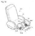
- Fig. 13 shows one example of the case where the lower-leg massage parts 320A and 320B rotate with a pneumatic tube in the chair-type massaging machine 300 having a lower-leg massage function according to Embodiment 3.
- Fig. 14 shows a state where the concave parts 321 and 322 have been turned upward by the pneumatic tube in the chair-type massaging machine 300.
- Fig. 15 shows a state where foot placing parts 325A and 325B have been turned upward by the pneumatic tube in the chair-type massaging machine 300.
- the lower-leg massage parts 320A and 320B are rotated by air tubes 500A and 500B provided on tube supporting parts 510A and 510B which are extended out forward from the front end of the chair part 111, so as to switch between the first surfaces and the second surface.
- the rotational axes 338A and 338B provided in the rotation centers T4 and T5, rotatably engage the lower-leg massage parts 320A and 320B with the seat part 111.
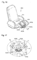
- Fig. 16 shows one example of the case where the lower-leg massage parts 420A and 420B are rotated by a pneumatic tube in the chair-type massaging machine 400 having the lower-leg massage function according to Embodiment 4.
- Fig. 17 shows a state where the concave parts 421 and 422 have been turned upward by the pneumatic tube in the chair-type massaging machine 400.
- Fig. 18 shows a state where the foot placing parts 425A and 425B have been turned upward by the pneumatic tube in the chair-type massaging machine 400.
- the lower-leg massage parts 420A and 420B are rotated by air tubes 520A and 530B provided on tube supporting part 530 which is extended out forward from the front end of the chair part 111, so as to switch between the first surfaces and the second surface.
- the rotational axes 438A and 438B provided in the rotation centers T6 and T7, engage the lower-leg massage parts 420A and 420B rotatably with the seat part 111.
- the present invention is utilizable in industries providing chair-type massaging machines having a lower-leg massage function.
Landscapes
- Health & Medical Sciences (AREA)
- Physics & Mathematics (AREA)
- Epidemiology (AREA)
- Public Health (AREA)
- Nonlinear Science (AREA)
- Veterinary Medicine (AREA)
- General Health & Medical Sciences (AREA)
- Animal Behavior & Ethology (AREA)
- Life Sciences & Earth Sciences (AREA)
- Pain & Pain Management (AREA)
- Physical Education & Sports Medicine (AREA)
- Rehabilitation Therapy (AREA)
- Mathematical Physics (AREA)
- Chemical & Material Sciences (AREA)
- Optics & Photonics (AREA)
- Crystallography & Structural Chemistry (AREA)
- General Physics & Mathematics (AREA)
- Massaging Devices (AREA)
- Percussion Or Vibration Massage (AREA)
Applications Claiming Priority (2)
| Application Number | Priority Date | Filing Date | Title |
|---|---|---|---|
| JP2004007111A JP2005198775A (ja) | 2004-01-14 | 2004-01-14 | 椅子型マッサージ機 |
| JP2004007111 | 2004-01-14 |
Publications (1)
| Publication Number | Publication Date |
|---|---|
| EP1555003A1 true EP1555003A1 (de) | 2005-07-20 |
Family
ID=34616867
Family Applications (1)
| Application Number | Title | Priority Date | Filing Date |
|---|---|---|---|
| EP04030737A Withdrawn EP1555003A1 (de) | 2004-01-14 | 2004-12-23 | Sesselartige Massagevorrichtung |
Country Status (5)
| Country | Link |
|---|---|
| EP (1) | EP1555003A1 (de) |
| JP (1) | JP2005198775A (de) |
| KR (1) | KR20050074919A (de) |
| CN (1) | CN1640377A (de) |
| TW (1) | TW200528046A (de) |
Cited By (4)
| Publication number | Priority date | Publication date | Assignee | Title |
|---|---|---|---|---|
| RU2283078C1 (ru) * | 2005-05-17 | 2006-09-10 | Леонид Михайлович Седлов | Устройство для массажа |
| DE102012003763A1 (de) * | 2012-02-24 | 2013-08-29 | Volkswagen Aktiengesellschaft | Modulares karosseriefestes Unterschenkelauflageteil mit pneumatisch veränderbarer Auflagefläche |
| CN113018144A (zh) * | 2021-03-09 | 2021-06-25 | 潘佳佳 | 一种下肢外胫夹康复训练方法 |
| CN113041116A (zh) * | 2021-03-09 | 2021-06-29 | 潘佳佳 | 一种下肢康复训练用辅助器械 |
Families Citing this family (5)
| Publication number | Priority date | Publication date | Assignee | Title |
|---|---|---|---|---|
| JP4903069B2 (ja) * | 2007-03-02 | 2012-03-21 | 株式会社フジ医療器 | マッサージ機 |
| CN102462603A (zh) * | 2010-11-01 | 2012-05-23 | 山东康泰实业有限公司 | 腿脚按摩传动装置 |
| JP6220620B2 (ja) * | 2013-05-21 | 2017-10-25 | 大東電機工業株式会社 | 椅子型マッサージ機 |
| CN108245371B (zh) * | 2018-03-08 | 2024-05-03 | 东莞摩可健康科技有限公司 | 一种防占位的按摩椅 |
| CN110269790A (zh) * | 2018-03-16 | 2019-09-24 | 香港中文大学 | 用于关节窝的可穿戴理疗仪 |
Citations (5)
| Publication number | Priority date | Publication date | Assignee | Title |
|---|---|---|---|---|
| JPH08257084A (ja) | 1995-03-27 | 1996-10-08 | Tec Corp | 椅子式エアーマッサージ機 |
| US5792082A (en) * | 1995-06-14 | 1998-08-11 | Kabushiki Kaisha Fuji Iryoki | Chair-type air massage device |
| JPH10295753A (ja) * | 1997-04-25 | 1998-11-10 | Family Kk | 椅子型マッサージ機 |
| EP0998894A1 (de) * | 1998-11-02 | 2000-05-10 | Family Kabushiki Kaisha | Sesselartige Massagevorrichtung |
| US20030006639A1 (en) * | 2001-06-15 | 2003-01-09 | Nobuzo Shimizu | Legrest-carrying chair |
-
2004
- 2004-01-14 JP JP2004007111A patent/JP2005198775A/ja not_active Withdrawn
- 2004-12-23 EP EP04030737A patent/EP1555003A1/de not_active Withdrawn
-
2005
- 2005-01-07 CN CNA2005100042382A patent/CN1640377A/zh active Pending
- 2005-01-11 TW TW094100688A patent/TW200528046A/zh unknown
- 2005-01-13 KR KR1020050003267A patent/KR20050074919A/ko not_active Ceased
Patent Citations (6)
| Publication number | Priority date | Publication date | Assignee | Title |
|---|---|---|---|---|
| JPH08257084A (ja) | 1995-03-27 | 1996-10-08 | Tec Corp | 椅子式エアーマッサージ機 |
| US5792082A (en) * | 1995-06-14 | 1998-08-11 | Kabushiki Kaisha Fuji Iryoki | Chair-type air massage device |
| JPH10295753A (ja) * | 1997-04-25 | 1998-11-10 | Family Kk | 椅子型マッサージ機 |
| EP0998894A1 (de) * | 1998-11-02 | 2000-05-10 | Family Kabushiki Kaisha | Sesselartige Massagevorrichtung |
| US20030006639A1 (en) * | 2001-06-15 | 2003-01-09 | Nobuzo Shimizu | Legrest-carrying chair |
| JP2003062024A (ja) | 2001-06-15 | 2003-03-04 | Daito Denki Kogyo Kk | フットレスト付き椅子 |
Non-Patent Citations (1)
| Title |
|---|
| PATENT ABSTRACTS OF JAPAN vol. 1999, no. 02 26 February 1999 (1999-02-26) * |
Cited By (5)
| Publication number | Priority date | Publication date | Assignee | Title |
|---|---|---|---|---|
| RU2283078C1 (ru) * | 2005-05-17 | 2006-09-10 | Леонид Михайлович Седлов | Устройство для массажа |
| DE102012003763A1 (de) * | 2012-02-24 | 2013-08-29 | Volkswagen Aktiengesellschaft | Modulares karosseriefestes Unterschenkelauflageteil mit pneumatisch veränderbarer Auflagefläche |
| CN113018144A (zh) * | 2021-03-09 | 2021-06-25 | 潘佳佳 | 一种下肢外胫夹康复训练方法 |
| CN113041116A (zh) * | 2021-03-09 | 2021-06-29 | 潘佳佳 | 一种下肢康复训练用辅助器械 |
| CN113041116B (zh) * | 2021-03-09 | 2022-09-09 | 泰兴市康森爱特传动设备科技有限公司 | 一种下肢康复训练用辅助器械 |
Also Published As
| Publication number | Publication date |
|---|---|
| KR20050074919A (ko) | 2005-07-19 |
| JP2005198775A (ja) | 2005-07-28 |
| TW200528046A (en) | 2005-09-01 |
| CN1640377A (zh) | 2005-07-20 |
Similar Documents
| Publication | Publication Date | Title |
|---|---|---|
| US7195604B2 (en) | Massage machine with recess having a bottom wall and opposite side walls that are inflatable | |
| EP1555003A1 (de) | Sesselartige Massagevorrichtung | |
| KR100399174B1 (ko) | 월풀을 이용한 발안마기능이 구비된 안마 의자 | |
| US20240122787A1 (en) | Multi-functional massager | |
| CN101547672A (zh) | 按摩机 | |
| HK1199394A1 (en) | Leg massage device and method for controlling leg massage device | |
| JP5010397B2 (ja) | マッサージ機 | |
| JP7324512B2 (ja) | マッサージ機 | |
| KR20040046354A (ko) | 차량용 전동식 풋 레스트 | |
| JP2009050391A (ja) | 椅子式マッサージ機 | |
| JP2002028207A (ja) | マッサージ機 | |
| JP2002325809A (ja) | マッサージ機 | |
| JP3988881B2 (ja) | マッサージ機 | |
| JP2002102384A (ja) | 血液循環を改善するためのペダル装置 | |
| JP2002369847A (ja) | 脚用空気マッサージ機及び椅子型マッサージ装置 | |
| JP4260041B2 (ja) | マッサージユニット | |
| JP7370065B2 (ja) | マッサージ機 | |
| JP2005270436A (ja) | 車いす | |
| EP1555004A1 (de) | Massagevorrichtung | |
| JP4515932B2 (ja) | マッサージ器 | |
| CN117243797A (zh) | 按摩机及施疗机构 | |
| JP2001161502A (ja) | 椅 子 | |
| JP4313583B2 (ja) | 車いす | |
| KR20260000408U (ko) | 발목 움직임 기능을 갖는 다리 및 발 마사지 장치 | |
| CN101829008A (zh) | 空气按摩机及按摩椅 |
Legal Events
| Date | Code | Title | Description |
|---|---|---|---|
| PUAI | Public reference made under article 153(3) epc to a published international application that has entered the european phase |
Free format text: ORIGINAL CODE: 0009012 |
|
| AK | Designated contracting states |
Kind code of ref document: A1 Designated state(s): AT BE BG CH CY CZ DE DK EE ES FI FR GB GR HU IE IS IT LI LT LU MC NL PL PT RO SE SI SK TR |
|
| AX | Request for extension of the european patent |
Extension state: AL BA HR LV MK YU |
|
| AKX | Designation fees paid | ||
| STAA | Information on the status of an ep patent application or granted ep patent |
Free format text: STATUS: THE APPLICATION IS DEEMED TO BE WITHDRAWN |
|
| 18D | Application deemed to be withdrawn |
Effective date: 20060121 |
|
| REG | Reference to a national code |
Ref country code: DE Ref legal event code: 8566 |