EP1554871B1 - Vorrichtung und verfahren zur erzeugung von neuen bildern unter benutzung von sich zeitlich verändernden bilddaten - Google Patents
Vorrichtung und verfahren zur erzeugung von neuen bildern unter benutzung von sich zeitlich verändernden bilddaten Download PDFInfo
- Publication number
- EP1554871B1 EP1554871B1 EP03758762A EP03758762A EP1554871B1 EP 1554871 B1 EP1554871 B1 EP 1554871B1 EP 03758762 A EP03758762 A EP 03758762A EP 03758762 A EP03758762 A EP 03758762A EP 1554871 B1 EP1554871 B1 EP 1554871B1
- Authority
- EP
- European Patent Office
- Prior art keywords
- image
- pixel
- value
- frame
- data
- Prior art date
- Legal status (The legal status is an assumption and is not a legal conclusion. Google has not performed a legal analysis and makes no representation as to the accuracy of the status listed.)
- Expired - Lifetime
Links
Images


Classifications
-
- G—PHYSICS
- G06—COMPUTING OR CALCULATING; COUNTING
- G06T—IMAGE DATA PROCESSING OR GENERATION, IN GENERAL
- G06T3/00—Geometric image transformations in the plane of the image
- G06T3/18—Image warping, e.g. rearranging pixels individually
-
- G—PHYSICS
- G06—COMPUTING OR CALCULATING; COUNTING
- G06T—IMAGE DATA PROCESSING OR GENERATION, IN GENERAL
- G06T11/00—2D [Two Dimensional] image generation
-
- H—ELECTRICITY
- H04—ELECTRIC COMMUNICATION TECHNIQUE
- H04N—PICTORIAL COMMUNICATION, e.g. TELEVISION
- H04N13/00—Stereoscopic video systems; Multi-view video systems; Details thereof
-
- H—ELECTRICITY
- H04—ELECTRIC COMMUNICATION TECHNIQUE
- H04N—PICTORIAL COMMUNICATION, e.g. TELEVISION
- H04N5/00—Details of television systems
- H04N5/222—Studio circuitry; Studio devices; Studio equipment
- H04N5/262—Studio circuits, e.g. for mixing, switching-over, change of character of image, other special effects ; Cameras specially adapted for the electronic generation of special effects
- H04N5/2625—Studio circuits, e.g. for mixing, switching-over, change of character of image, other special effects ; Cameras specially adapted for the electronic generation of special effects for obtaining an image which is composed of images from a temporal image sequence, e.g. for a stroboscopic effect
-
- G—PHYSICS
- G06—COMPUTING OR CALCULATING; COUNTING
- G06T—IMAGE DATA PROCESSING OR GENERATION, IN GENERAL
- G06T2210/00—Indexing scheme for image generation or computer graphics
- G06T2210/44—Morphing
Definitions
- the present invention relates to method and apparatus for generating images, and it particularly relates to a technology in which moving images shot by a camera are processed and the thus processed moving images are outputted anew.
- US-A-5459830 discloses an image generating method, including:
- the inventors of the present invention have come to search for an innovative image-processing method by which to be able to obtain novel and special-effect-like images.
- the inventors of the present invention invented the present invention on the basis of the above-mentioned recognition, and an object of the present invention is to obtain entertaining images.
- the present invention was made in view of any of the following objectives or other objectives understood via description of the present patent specifications. Namely, the objectives include improving the efficiency of image processing, reducing a load caused by the image processing, new proposals to improve the image processing technology and so forth.
- a preferred embodiment according to the present invention relates to an image generating method as defined in claim 1.
- the contents of a change are determined by setting the surface in various ways, and new moving pictures that differ from the contents of the original moving pictures are outputted.
- the "original moving pictures” may be images presently shot by a camera, or may be images, stored beforehand in a recoding medium, such as images coded by an MPEG format or the like.
- "Projecting onto a plane” is such that, if projected onto a plane on time axis, images to be projected on this plane will be the result of this "projecting onto a plane”. Specifically speaking, it means that, when the cut surface is directly viewed from the direction of time axis, the images to be projected on this cut surface is equal to those projected on the plane.
- “Varying the cut surface in time” may be realized, for example, by moving the cut surface along time axis while the surface shape of the cut surface is kept intact. By moving the cut surface as time elapses, smooth and continuous new moving pictures are obtained.
- the surface may be a plane. The projected image varies depending on what kind of a surface shape is set.
- the image generating apparatus may further include an image input unit which acquires as the original moving pictures the images shot by the camera and sends these acquired images to the image memory.
- the images shot are image-processed in real time, so that unique, mysterious or special-effect-like images that differ from the actual status of an object can be displayed on a screen.
- a plurality of frames contained in original moving pictures are sequentially stored in a ring buffer (see Fig. 3 ), and data are, for each scanning line, read out from different frames, so that the thus read-out data are displayed on a screen as a new frame.
- data on pixels on a scanning line located at the upper edge of a screen are read out from newer frames whereas those at the lower edge thereof are read out from previous frames which are older in time.
- displayed is a strange and mysterious image which differs from an actual object.
- Fig. 1 illustrates and expresses a state, in a virtual manner, where frames of the original moving pictures appear continuously along time axis.
- the original moving pictures are regarded and grasped as two-dimensional images that change along the time axis.
- a rectangular-parallelopiped space 10 (hereinafter referred to as a "box space” also) extends in the direction of time axis t as time elapses.
- a cross section vertical to the time axis t represents a frame.
- a frame is a set of pixels represented by the coordinates of a plane formed by x axis and y axis. This box space 10 is cut by a surface having a desired shape.
- the box space 10 is cut by a slope face which is parallel to the x axis, in the direction from the x axis above toward a line below as time elapses from time to through time t 1 , as shown in Fig. 1 .
- a slope face which is parallel to the x axis, in the direction from the x axis above toward a line below as time elapses from time to through time t 1 , as shown in Fig. 1 .
- the cut surface 14 moves along the time axis t as the time elapses.
- the cut surface 14 is defined in a manner such that it has continuous width in the direction of time axis t. Images contained in this width are synthesized and those synthesized images serve as frames displayed actually on the screen.
- the current frame 12 corresponds to a frame which should have been at the timing of being presently scanned in the normal display scheme. Let the present position of the current frame 12 on the time axis be at time t 0 . Then, frames prior to time t 0 , which are, for example, respective frames positioned at t 1 , t 2 , t 3 and t 4 , correspond to frames that should have been already displayed under the normal display timing. In this first embodiment, however, the display of the frames prior to time to are actually delayed. Data on pixels contained in each frame are outputted in a manner such that the output of the data is delayed in sequence for each pixel line in the horizontal direction. Data of each pixel contained in a single pixel line are read out at the same scanning timing and then displayed.
- a pixel line at the highest point is outputted at the normal scanning timing. Thereafter, a pixel line positioned one pixel below the one at the highest point is outputted with a delay of one frame. Thus, the lower the order of the pixel line is, it is outputted at the further delayed timing.
- Figs. 2A and 2B illustrate a screen showing a photographed object and one showing what is actually displayed, respectively, and are also provided to compare the former with the latter.
- Fig. 2A shows an image shot, and the image of this object is equivalent to the current frame 12.
- the object waves his/her hand 16 slowly.
- Fig. 2B is an image that appears in the cut surface 14 shown in Fig. 1 , and is the image where the object of Fig. 2A is actually displayed on the screen.
- the object having a shape different from the proper and natural object itself is displayed on the screen.
- the position of the hand 16 changes from a left side to a midpoint, right side, midpoint and left side in this order, so that the image of the hand 16 at the left-side position and the image at right-side position appear alternately by reading out data for each scanning line from the different past frames. Since the data on the same scanning line are read out from the frames of the temporally same scanning timing, no curvature or deformation is caused in the horizontal direction. In the vertical direction, however, the hand 16 is displayed in a manner such that the shape of the hand 16 is meandering-like and curved in the left and right sides.
- this object waving the hand 16 hardly moves except for the hand 16.
- the curvature or deformation is almost absent because there is no difference in the display position thereof.
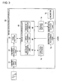
- Fig. 3 is a block diagram showing functions of an image generating apparatus according to the first embodiment.
- the structure of the image generating apparatus 50 can be realized by elements such as a CPU and the like of an arbitrary computer.
- the structure of the image generating apparatus 50 can be realized by elements such as a CPU and the like of an arbitrary computer.
- software it is realized by programs or the like having functions of data storage, image processing and drawing, but illustrated and described in Fig. 3 are functional blocks that are realized in cooperation with those. Thus, these functional blocks can be realized in a variety of forms by hardware only, software only or the combination thereof.
- the image generating apparatus 50 is comprised of an image input unit 52 which acquires images shot by a camera as original moving pictures, and sends frames contained in the original moving pictures to an image memory, a ring buffer 56 which serves as the image memory that sequentially stores the original moving pictures along time axis, a buffer control unit 54 which controls the read and write of a frame from and to the ring buffer 56, an image conversion unit 60 which converts frames stored in the ring buffer 56 into frames for use with display, a function storage 70 which stores functions referred to at the time of frame conversion, and a display buffer 74 which stores the frames for use with display.
- the image input unit 52 may include a CCD that captures digital images, and a conversion unit that obtains digital images by A-D conversion.
- the image input unit 52 may be realized as a device which is provided externally in a detachable manner and is mounted on the image generating apparatus 50.
- the buffer control unit 54 sequentially records the frames of the original moving pictures inputted by the image input unit 52, to a region indicated by a write pointer of the ring buffer 56.
- the image conversion unit 60 For each pixel contained in the current frame 12, the image conversion unit 60 reads out data corresponding to the pixel from the frame recorded in the ring buffer 56, and synthesizes the data.
- the image conversion unit 60 includes a decision processing unit 62 which determines from which frame the data shall be read out for each pixel, a data acquiring unit 64 which reads out data from the frame determined by the decision processing unit 62, and an image formation unit 66 which forms a frame by synthesizing data for each read-out pixel line.
- a decision as to from which frame the data shall be read out is made based on and defined by the following equation (1).
- P Fr x y t 0 P ⁇ x , y , t 0 - y
- x and y are pixel coordinates on the current frame 12
- t 0 is a time value on the time axis t.
- P Fr is a pixel value of each pixel in the actually outputted frame.
- the time value of a frame to be outputted is a function of the coordinate y only.
- the function expressed by the equation (1) is stored in the function storage 70.
- Other optional functions are also stored in the function storage 70.
- a user can set to adopt which function to use via an instruction acquiring unit 72.
- Data for each pixel read out by the data acquiring unit 64 are sequentially written to the display buffer 74 by the image formation unit 66 which has a function serving as a graphic ship, so that a frame is composed thereby.
- the image generating apparatus 50 further includes an instruction acquiring unit 72 which receives an instruction from the user, an image data output unit 76 which outputs frames stored in the display buffer 74, and a monitor 78 which displays the outputted frame on a screen.
- the monitor 78 may be a display provided externally to the image generating apparatus 50.
- the image data output unit 76 reads out image data from the display buffer 74 which stores the image data for one frame, then converts them into analog signals and sends them out to the monitor 78.
- the image data output unit 76 outputs sequentially the frames stored in the display buffer 74 so as to output new moving pictures.
- Fig. 4 is a flowchart showing the steps of converting the original moving pictures into new moving pictures according to the first embodiment.
- the frames contained in the original moving pictures are recorded in the t-th region of the ring buffer 56 (S12).
- the total of T 0 regions for one frame are provided.
- a readout pointer T that designates a read-out position of data corresponding to the line number n (S16).
- the readout pointer T is smaller than 0 (S18Y), such a readout pointer does not actually exist. Thus, the readout pointer T is moved to an ending side of the ring buffer 56 (S20). Stating more concretely, the number of regions To of the ring buffer 56 is added to the readout pointer T.
- the data acquiring unit 64 reads out the line number n from the frames stored in the region of the readout pointer T in the ring buffer 56, and the image formation unit 66 copies the data corresponding to this read-out number to the region of the line number n of the display buffer 74.
- the image data output unit 76 reads out frames from the display buffer 74, outputs the frames as video data and has the monitor 78 display the frames on the screen (S34).
- the processings of S12 through S34 are repeated until the termination of the display is instructed (S36).
- the data are read out from the same frame in units of pixel line and then written to the display buffer.
- the pixel lines are primarily a plurality of pixel sets which are the same as scanning lines arranged in the horizontal direction, so that the pixel lines are the data which should be read out at the same scanning timing in the normal setting.
- the read and write are efficiently processed in the course of scanning, and the excessive increase of a load due to the image conversion in the present embodiment can be prevented.
- the decision processing unit 62 may determine a frame to be read out from, according to the coordinate x. For instance, as for a pixel line located at the left hand edge of the screen, the data thereof are read out from the left hand edge of the current frame 12 whereas, as for a pixel line at the right hand edge of the screen, the data thereof are read out from the right-hand-edge pixel line of a frame at time t 2 shown in Fig. 1 . Then, the cut surface thereof will be a surface cut by a slope face over time to to time t 2 where this slope face is parallel to the y axis.
- the decision processing unit 62 may determine a frame to be read out from, according to both x and y coordinates. For instance, as for a pixel at the upper left edge of the screen, the data thereof are read out from the upper left edge of the current frame 12 whereas, as for a pixel at the lower right edge of the screen, the data thereof are read out from the lower-right-edge pixel of a frame at time t 2 shown in Fig. 1 .
- the scanning line may be set in the vertical direction instead of the horizontal direction. In that case, further efficient image conversion can be realized by determining the frame to be read out from, according to the x coordinate.
- a depth value (Z value) specified for each pixel In a second illustrative example not forming part of the actual invention, data are read out from different frames according to a depth value (Z value) specified for each pixel.
- Z value depth value
- the processing carried out by the second illustrative example not forming part of the actual invention differs from that of the first embodiment where the frame is determined according to the y coordinate of a pixel.
- the data of one situated closer to the camera is read out from the older frame.
- Fig. 5 illustrates, in a virtual manner, the original moving pictures as a box space, according to the second embodiment.
- the Z value of a first image 20 is set to "120" while the Z value of a second image 24 is set to "60".
- the delayed amount of the display timing increases in proportion to the Z value.
- Each pixel of the frames actually displayed on the screen is defined by the following equation (2).
- P Fr x y t 0 P ⁇ x , y , t 0 - Z x y t 0
- Z(x, y, t 0 ) is the Z value of a pixel unit at the present time.
- the frame from which the pixel data thereof are read out goes further back from t 0 toward the direction of t 1 and t 2 on time axis t.
- Data corresponding to the first image 20 are read out from a region which is indicated as a third image 22 in a frame on time t 2 .
- Data corresponding to the second image 24 are read out from a region which is indicated as a fourth image 26 in a frame at time t 1 .
- the region of the third image 22 takes a time value of t 2 whereas the region of the fourth image 26 takes a time value of t 1 .
- the other regions take a time value of t 0 .
- the pixels that constitute the first image 20 have greater Z values than those of the second image 24, and the data thereof are read out from older frames in time. Namely, since the pixels that constitute the second image 24 have smaller z values than those of the first image 20, the time duration required for going back toward older frames is shorter.
- Figs. 6A and 6B are provided to compare a screen showing an object shot with a screen showing what is actually displayed.
- Fig. 6A represents the object shot and, the object shot in this case is a person 30 who raised his/her hand and just started waving the hand to the right and left slowly and an automobile 32 which runs in the back.
- Fig. 6B represents an image where the object shown in Fig. 6A is actually projected on the screen.
- the object is displayed on the screen in a state that differs from a normal setting. Namely, the closer a region thereof is to the camera, the further delayed the display timing thereof is. Now, the person 30 is the object closest to the camera, thus the amount of delay in display timing is the greatest, in particular.
- the image generating apparatus 50 has basically the same structure as the apparatus shown in Fig. 3 .
- the decision processing unit 62 computes an amount of time to go back in the past according to each Z value, and then determines for each pixel cell the frame from which the data are to be read out.
- the frame or frames from which the data are to be read out will be also referred to as a source frame or source frames.
- the image input unit 52 according to the second illustrative example includes a distance-measuring sensor by which a Z value of each pixel cell is detected.
- a distance-measuring method may be a laser method, an infrared illumination method, a phase detection method or the like.
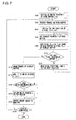
- Fig. 7 is a flowchart showing the steps of generating new moving pictures by reading out data from the frame according to a Z value, in the second illustrative example.
- the frames contained in the original moving pictures are recorded in the t-th region of the ring buffer 56 (S102).
- Calculated is a readout pointer T that designates readout positions of data corresponding to the pixels x and y (S106).
- the decision processing unit 62 computes the readout pointer T according to the Z value for each pixel.
- the data acquiring unit 64 reads out data of a pixel P x,y from the frames stored in a region of the readout pointer T in the ring buffer 56. Then, the image formation unit 66 copies this read-out data to a region of the pixel P x,y in the display buffer 74 (S108).
- the pixel P x,y is moved to the next pixel (S112).
- the processings of S106 through S112 are repeated until the pixel P x,y becomes the last pixel.
- the image for one frame is written to the display buffer 74 (S110Y) and this is drawn by the image formation unit 66 (S114).
- a third illustrative example according to the present invention differs from the first and second illustrative example in that images are synthesized by reading out data of pixels having desired attribute values from a plurality of frames.
- the above-mentioned attribute value is a pixel value; for example, when the images are synthesized by reading out image values having red color components only, mysterious and special-effect-like images are obtained where the desired color only is lingering on as if it were an after-image.
- Fig. 8 illustrates, in a virtual manner, the original moving pictures as a box space, according to the third illustrative example.
- a person 30 projected on the frames at time t 0 , t 1 , t 2 and t 3 in the box space 10 is an object who slowly waves the hand, holding a red material object, in the left and right directions.
- the respective display positions of the red material object images 34, 35, 36 and 37 projected on the respective frames differ from one another.
- frames to be utilized for image composition or image synthesis are determined in advance among a plurality of old frames stored in the ring buffer 56.
- the four frames at time t 0 , t 1 , t 2 and t 3 are used for the image composition.
- These four frames are a plurality of surfaces arranged at fixed time intervals within the box space 10.
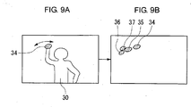
- Figs. 9A and 9B are provided to compare a screen showing an object shot and a screen showing what is actually displayed.
- Fig. 9A represents the object shot.
- Fig. 9B represents an image where the object shown in Fig. 9A is actually projected on the screen.
- the red color components only are extracted and synthesized on this screen, so that the images 34, 35, 36 and 37 of red material objects only are displayed and the background thereof is white or black.
- the data acquiring unit 64 reads the data for each pixel based on the equation (3), and determines whether the images are to be synthesized or not. In this manner, the pixel extraction by color is realized.
- the pixel value of the red color component is set as the alpha value in the equation (4), it is not limited thereto. If the alpha value is set to P G or P B , then a green color component or blue color component only is extracted and synthesized. Accordingly, if any specified color component is contained in the object, the particular portion containing the specified color component only is displayed as if it were a lingering after-image.
- the image generating apparatus 50 has basically the same structure as the apparatus shown in Fig. 3 .
- the decision processing unit 62 selects a plurality of frames at fixed time intervals.
- the data acquiring unit 64 and the image formation unit 66 synthesize the read-out data at a ratio determined by a pixel value for each pixel.
- Fig. 10 is a flowchart showing the steps of generating from the original moving pictures the moving images where a desired color component is extracted, according to the third embodiment.
- the frames contained in the original moving pictures are recorded in the t-th region of the ring buffer 56 (S52).
- the position of a readout pointer T in the ring buffer 56 is calculated as read-out positions of data corresponding to the pixels x and y (S56).
- the data acquiring unit 64 reads out data of a pixel P x,y from the frames stored in a region of the readout pointer T in the ring buffer 56. Then, the image formation unit 66 copies this read-out data to a region of the pixel P x,y in the display buffer 74 (S58).
- An alpha value á x,y of the pixel P x,y is computed and set (S60).
- the pixel P x,y is not yet the last pixel in the display buffer 74, namely, when the pixel P x,y is not the pixel of the lower right edge (S62N)
- the pixel P x,y is moved to the next pixel (S64).
- the processings of S56 through S62 are repeated until the pixel P x,y becomes the last pixel in the display buffer 74.
- the image for one frame is written to the display buffer 74 (S62Y) and this is drawn by the image formation unit 66 (S66).
- the predetermined number I is "3" and the synthesizing is repeated four times until the number i of frame synthesizing becomes "3" counted from "0".
- the number i of frame synthesizing reaches the predetermined number I (S68Y)
- "1" is added to the write pointer t (S70).
- the write pointer t indicates an ending region of the ring buffer 56 (S74)
- the write pointer t is returned to the top region of the ring buffer 56 (S74).
- the image data output unit 76 outputs the drawn image data to the monitor 78 (S76).
- the processings of S52 through S76 are repeated unit the termination of the display is instructed (S78). In this manner, data of the desired color component only are read out from the past frames in units of pixel and then written to the display buffer.
- three colors RGB are extracted together, so that not only the red material object images 34 - 37 but also the person 30 appear simultaneously on the screen shown in Fig. 9B .
- a fourth illustrative example not forming part of the actual invention according to the present invention differs from the third illustrative example not forming part of the actual invention in that the attribute value in this fourth illustrative example not forming part of the actual invention is a value that indicates the order of approximation between a desired image pattern and an actual image.
- the attribute value in this fourth illustrative example not forming part of the actual invention is a value that indicates the order of approximation between a desired image pattern and an actual image.
- Fig. 11 illustrates, in a virtual manner, the original moving pictures as a box space, according to the fourth embodiment.
- a current frame 20 contained in the box space 10 contains a first image 40.
- the pixels constituting the first image 40 has higher order of approximation to the image pattern, compared with those in the other regions.
- the data corresponding thereto are read out from frames in the past according to the order of approximation by further going back along time axis.
- time t 2 along the time axis
- the data are read out from the position of the second image 42 in a frame having the time value t 2 .
- the cut surface of the box space 10 takes a time value of t 2 in the region of second image 42 only and takes a time value of t 1 in the other regions.
- the cut surface has discrete widths in the direction of time axis.
- the image generating apparatus 50 has basically the same structure as the apparatus shown in Fig. 3 .
- the user specifies the image patterns via the instruction acquiring unit 72, and the decision processing unit 62 processes matching between the image pattern and the image of a frame. As a result thereof, the order of approximation to the image pattern is detected pixel by pixel.
- the decision processing unit 62 determines, for each pixel, a frame from which the data are to be read out, according to the order of approximation thereof.
- the image pattern as an object to which matching is computed is specified by the user, and the matching is computed between the current frame 12 and the image pattern so as to detect the order of approximation, denoted by "s", for each pixel. Namely, as for a pixel in the image region which is approximate to the image pattern, the order of approximation of the image region is set.
- Steps S100 to S104 are the same as those in the second illustrative example not forming part of the actual invention.
- the steps taken thereafter are also the same as those in the second illustrative example not forming part of the actual invention.
- this fifth illustrative example not forming part of the actual invention data are read out from separate frames and synthesized according to attribute values of pixels.
- This attribute value differs from that in the third and fourth illustrative example not forming part of the actual invention in that it is a value that indicates the degree of temporal change of an image region. For example, among the objects, a region thereof which is moves fast or moves greatly has a large image change in time, so that the data are read out from the older frames. Thus, the display of a region, contained in the original moving pictures, which has a large image change can be delayed, so that the larger the image change is, the further delayed the display of the object's region will be.
- the image generating apparatus 50 has basically the same structure as the apparatus shown in Fig. 3 .
- the degree of change in time between a target frame and a frame immediately prior to this target frame is detected, for each pixel, by a decision processing unit 62.
- the decision processing unit 62 determines frames from which data are to be read out, according to its degree of change.
- T-th frame and (T-1)th frame in the ring buffer 56 are compared pixel by pixel, and the degree of change, denoted by "c", is detected.
- a sixth illustrative example not forming part of the actual invention according to the present invention differs from the first embodiment in that the user can freely determine and define, by using interface on the screen, from which frame the data is to be read out for each scanning line.
- the sixth illustrative example not forming part of the actual invention will be described hereinbelow with the emphasis on different points from the first embodiment.
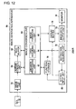
- Fig. 12 is a block diagram showing a structure of an image generating apparatus.
- the image generating apparatus 50 mainly differs from the image generating apparatus 50 according to the first embodiment shown in Fig. 3 in the point where the apparatus shown in Fig. 12 includes a setting input unit 80.
- the setting input unit 80 acquires input of a setting value used to define the cut surface 14 of Fig. 1 , via an instruction acquiring unit 72 operated by a user.
- the instruction acquiring unit 72 may be, for instance, a touch panel attached to the screen of the monitor 78. In that case, the value that indicates a position on the touch panel pressed by the user is inputted as the operation contents.
- the instruction acquiring unit 72 sends to the setting input unit 80 the user's operation contents to change the graph displayed on the monitor 78.
- the decision processing unit 62 reads out the function set by setting input unit 80 from the function storage 70, and determines from which frame the data are to be read out for each pixel line based on this new function.
- the box space 10 shown in Fig. 1 is cut by a surface defined by the function set by the setting input unit 80, and an image appearing on the cutting surface is outputted as an actual frame instead of the current frame 12.
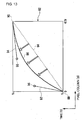
- Fig. 13 shows an example of a screen of a monitor that displays a graph of a function determined by the setting input unit.
- the user can change the straight line 84 to a Bezier curve 86.
- the Bezier curve 86 is a curve connecting a first endpoint 88 to a second endpoint 90, and a shape of this curve is determined by positions of a first control point 96 and a second control point 98.
- the positions of the first control point 96 and the second control point 98 are determined by the user's varying the position and the length of a first handle 92 or a second handle 94. If the function set by the setting input unit 80 is specified by the Bezier curve 86, obtained are images where the data read out from frames close to the present one and the data read out from frames in the past are mixed together for each pixel line. For example, via the setting input unit 80 the user can specify a periodic curve, such as a sinusoidal wave curve, by the Bezier curve 86.
- the function is specified by the Bezier curve 86, there may be provided a structure, as a modified example, in which the function is specified by other curves such as B-spline curve and the like.
- a seventh illustrative example not forming part of the actual invention according to the present invention differs from the sixth illustrative example not forming part of the actual invention in that the setting input unit 80 acquires, as one of the setting values, the coordinates of characteristic points in the current frame 12 and the function is defined by this coordinates of characteristic points.
- the seventh illustrative example not forming part of the actual invention will be described hereinbelow with the emphasis on different points from the sixth illustrative example not forming part of the actual invention.
- An instruction acquiring unit 72 is a touch panel attached to the screen of a monitor 78, too.
- a plurality of continuous values representing the coordinates of the pressing points are sent to a setting input unit 80.
- the setting input unit 80 Based on the thus obtained coordinate values, the setting input unit 80 recognizes a region surrounded and covered by the plurality of pressing points, and generates functions to determine the surrounding region so as to be recorded in a function storage 70.
- the data are read out from the past frames as to pixels contained in the surrounding region while the data are read out from the current frames 12 as to pixels not contained in the surrounding region.
- the box space 10 shown in Fig. 1 is cut by a surface defined by the function of the coordinates acquired by the setting input unit 80, and an image appearing on the cutting surface is outputted as an actual frame instead of the current frame 12.
- the user can utilize the image generating apparatus 50 as an authoring tool and can generate mysterious and unique images by specifying an arbitrary region on the touch panel.
- An eighth illustrative example not forming part of the actual invention according to the present invention differs from the other embodiments in that a function is defined beforehand in a manner such that a predetermined varying shape emerges to the screen, and the data are read out from a frame which is determined based on this function.
- the function is defined beforehand in a manner such that a varying shape of wave such as a water ring emerges onto the screen.
- a decision processing unit 62 determines characteristic points in the current frame 12. Similar to the sixth and seventh illustrative example, the characteristic points are specified by the user via a touch panel attached to the screen of a monitor 78 where this touch panel serves as an instruction acquiring unit 72.
- the decision processing unit 62 determines a source frame and a pixel coordinate so that a wave-like shape of water rings emerges from the characteristic point as a center thereof.
- the source frame is a frame from which the data are to be read out. For example, in order to express the stereoscopic figure of the water rings, it is assumed that a circle or circles are displayed in the radial direction from the characteristic point, and the decision processing unit 62 determines source frames with gradually differing time values for each radial circle.
- the change of the gradually differing time value is defined so that it becomes a periodic change. Thereby, the unevenness as in the water rings can be expressed.
- the decision processing unit 62 shifts the pixel coordinate to be read out, by a predetermined amount of pixels in a predetermined direction. Thereby, the refraction of light caused by the water rings can be expressed.
- a ninth illustrative example not forming part of the actual invention according to the present invention differs from the seventh and eighth illustrative example where the touch panel is used as an instruction acquiring unit 72 that inputs the characteristic points in that the characteristic points are determined based on information contained in the current frame 12.
- a decision processing unit 62 determines the characteristic points based on a pixel value of each of pixels contained in the current frame 12. For example, a high-speed flickering LED is incorporated into an object so as to become a part of the object, and the decision processing unit 62 recognizes the flickering position by specifying a region where the pixel value intermittently changes between two values in the continuously inputted current frames 12. The decision processing unit 62 determines the flickering position to be the coordinates of the characteristic points. As a modified example, the decision processing unit 62 may determine the characteristic points using fixed coordinates.
- the decision processing unit 62 may determine a pixel to be a characteristic point if any one of the following factors which are the pixel value, Z value, order of approximation to a desired pattern and a change of the pixel value of the pixel falls into a predetermined range.
- a tenth illustrative example not forming part of the actual invention according to the present invention differs from the other embodiments in that an image input unit 52 acquires not only the original moving pictures but also audio data.
- the audio data that the image input unit 52 acquires are inputted in synchronism with the original moving pictures, so as to be sent to a ring buffer 56.
- a decision processing unit 62 determines at least one of a source frame, readout timing, alpha value and characteristic points.
- the decision processing unit 62 may determine the source frame and the readout pixel in a manner such that the shape as described in the eighth embodiment emerges to the screen. For example, if the change of sound volume exceeds the threshold value in part of a frequency domain, then the decision processing unit 62 may determine the characteristic points in the eighth and ninth illustrative examples according to the frequency domain.
- a predetermined graphic is composed in the vicinity of the position of a pixel according to an attribute value of the pixel contained in the target frame.
- the attribute value is a numerical value that indicates the degree of temporal change of an image region. For example, a region that moves fast or greatly in an object is continuously displayed so that an artistically or dramatically represented object having the form of particle is deformed in a diffusing manner starting from a pixel, whose temporal change is greater, toward its periphery. In this manner, a directing and manipulating effect such as a paper-snowfall-like effect displayed on the screen can be produced in the periphery of a main object in the original image such as a moving region or site.
- An image generating apparatus 50 has a similar structure to that of the apparatus shown in FIG. 3 .
- a decision processing unit 62 detects, for each pixel, the degree of temporal change of a pixel value of an image region constituting a frame, between the current frame 12 and a previous frame which is a frame before the current frame 12 in time.
- the decision processing unit 62 regards a pixel as a center position for a directing and manipulating object if the degree of change of this pixel exceeds a predetermined threshold value.
- a pixel among them which has the greatest degree of change may be determined to be the center position and a plurality of directing and manipulating objects may be displayed in a diffusing manner around the center position.
- the decision processing unit 62 may determine a movement direction of the directing and manipulating object based on a difference between a pixel in the current frame 12 and a pixel in the previous frame where each of the two pixels has the greatest degree of change in each frame.
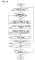
- Fig. 14 is a flowchart showing the steps of generating a directing and manipulating object.
- a current frame 12 is inputted as a processing object (S150). If a reproduction processing is performed not immediately after the start of an input of the current frame 12 (S152N), a change of pixel values is extracted between the current frame 12 and a frame immediately prior thereto in time (S154), a position where the change of pixel values is greatest is detected (S156), and a vector of positions whose change of pixel values are greatest is determined to be the movement direction of the directing and manipulating object (S158).
- the reproduction processing is performed immediately after the start of an input of the current frame 12, there is no such a frame immediately prior thereto, so that the processings S154 through S158 are skipped (S152Y).
- the current frame 12 is stored separately so as to be compared with the next frame (S160).
- An image of the directing and manipulating object to be displayed is generated around the periphery of the detected position in S156 as a center (S162).
- the thus generated directing and manipulating object and the current frame 12 are superposed, so that a drawing to be displayed is processed (S164).
- the directing and manipulating object is displayed while being moved in the movement direction determined by S158 (S166N).
- the decision processing unit 62 may determine the position to perform the directing and manipulating effect according to color component, contour, luminance, Z value, locus of motion or the like.
- the position where the directing and manipulating effect is to be produced may be determined according to the size of a pixel value such as a "position containing the most of red color components in the image", or a contour line whose difference of pixel values thereof between adjacent contours in a single frame is maximum may be determined as the directing and manipulating position.
- the "position where the directing and manipulating effect is to be produced” will be hereinafter referred to simply as a "directing position” also.
- a portion whose difference of pixel values thereof between, for example, adjacent "red contours" is greater than the threshold value and whose color component is greater than a threshold value may be determined as the directing position.
- a portion where the luminance is greater than a threshold value may be determined to be the directing position, and a portion having a specific range of Z values may be determined to be the directing position. If a plurality of the past frames are stored for within a limit of a fixed period of time, a locus of characteristic points which are extracted on the basis of a certain criterion can be detected.
- the directing and manipulating effect may be produced along such the locus.
- the decision processing unit 62 may display a linear object or character to which a shining color or the like is applied, or an object such as a symbol. Also, the decision processing unit 62 may produce a directing and manipulating effect where the transparency of a characteristic region extracted from the current frame 12 is changed to a semi-transparent state, so as to be superposed to the past frame.
- the decision processing unit 62 may determine the size or moving speed of the directing and manipulating object to be displayed, based on the attribute values such as the coordinates, Z value and pixel value of each pixel, the order of approximation with a desired image pattern and a rate of change in the pixel value.
- the alpha value used to compose the directing and manipulating object may be a fixed value or different values for the respective pixels.
- the alpha value may be set according to the attribute values such as the coordinates, Z value and pixel value of each pixel, the order of approximation with a desired image pattern, the degree of change in the pixel value and so forth.
- Fig. 15 is a flowchart showing the steps of applying a directing and manipulating effect to the current frame 12.
- the type of the directing and manipulating effect to be applied to the current frame 12 is determined based on an instruction from the user (S200).
- the current frame 12 where the directing and manipulating effect is produced is inputted (S202).
- a portion where the difference of values of pixels adjacent to each other within the current value 12 exceeds the threshold value is extracted as a contour (S204), and a position where the difference of the pixel values becomes a maximum is determined to be a position where the directing and manipulating effect is to be produced (S206).
- the directing and manipulating effect is applied to the thus determined position (S208), and a drawing for displaying the images where the directing and manipulating effect is produced is processed (S210).
- the above processings S202 to S210 are repeatedly performed on the current frame 12 (S212N) until the termination of display (S212Y), so as to apply the directing and manipulating effect thereon.
- a reproduction frame rate is varied locally according to a change of an attribute value of pixels contained in a target frame.
- the cut surface 14 is varied with time at a different rate for each image region according to an attribute value of an image region that constitutes a two-dimensional mage, so that the frame rate of new moving pictures to be outputted from the image data output unit 76 is varied partially.
- the degree of change of a pixel value in time is greater than a threshold value, for example, the time intervals at which the data are read out from a frame is made longer so as to lower the reproduction frame rate.
- An image generating apparatus 50 has basically the same structure as one shown in Fig. 3 .
- a decision processing unit 62 may vary the frame rate on the pixel-by-pixel basis or may vary the frame in units of object which is extracted based on a pixel value thereof.
- the decision processing unit 62 may extract the object in a manner such that a few pixels surrounding the pixel are included as part of a range in question. In this case, a portion, such as an edge of the object, whose pixel value changes gradually may be included as part of the object and processed, too.
- the decision processing unit 62 determines a frame rate after this change.
- the frame rate may be set according to the degree of temporal change in the pixel value of the region, and the frame rate of a region whose rate of change is greater may be set to a lower value.
- the decision processing unit 62 determines, for each pixel, the time interval between a source frame and a next frame to be read.
- the decision processing unit 62 may vary the frame rate with time. For example, the decision processing unit 62 sets first the frame rate to a low rate and gradually increases the frame rate so that it catches up with the display timing of the other pixels that surround this pixel.
- a structure may be such that the user can set, via the instruction acquiring unit 72 as shown in Fig. 12 , whether or not a processing is performed in a manner such that the edge of the object is included in the range of the object.
- the frame rate of a pixel having a predetermined range of Z values in the current frame 12 may be varied.
- the frame rate of a position having a predetermined order of approximation with a desired image pattern in the current frame may be varied. In other words, the frame rate is controlled on the pixel-by-pixel basis here.
- data of a pixel having a predetermined attribute value in a target frame are read out from a previous frame in time instead of from the target frame.
- data of a pixel value corresponding to the black color are read out from an old frame, so that a dramatic representation can be produced as if the partially past images were viewed from a window of a trimming shape.
- An image generating apparatus 50 has basically the same structure as one shown in Fig. 3 .
- the decision processing unit 62 according to the present illustrative example not forming part of the actual invention extracts from the current frame 12 a region having a predetermined range of pixel values, and at the same time determines a source frame of the region.
- the source frame may be a frame in the past obtained by going back along time axis for a prefixed time duration, or may be determined according to an attribute value such as the coordinates, Z value, pixel value of each pixel, order of approximation with a desired image pattern, magnitude of change in pixel value, or the like.
- the decision processing unit 62 may extract a region that also includes a few surrounding pixels. For example, a region corresponding to a mouth together with a few pixels surrounding the mouth are extracted from a human face, so that a portion, such as an edge of an object, where the pixel value gradually changes is extracted without fail.
- the data are read out from previous frames in time in the above embodiments. However, if future frames in time are also stored in the ring buffer 56, the data may be read out from these future frames.
- a pixel value is added to a pixel according to a change of an attribute value of the pixel contained in a target frame, so as to change the color.
- a directing and manipulating effect can be applied to the original image in a manner such that a region that moves greatly in an object is displayed in red or the like.
- An image generating apparatus 50 according to the fourteenth illustrative example has basically the same structure as one shown in Fig. 3 .
- the decision processing unit 62 according to the present illustrative example adds a predetermined value to the pixel value of a pixel so that the pixel whose degree of change in the current frame 12 is large is displayed in red. Thereafter, as for the pixel to which the predetermined value is added, a pixel value to be added to this pixel is gradually reduced with time and, as a result thereof, an after-image leaving a trail of red color behind can be displayed.
- the structure thereof may be such that data of a pixel that greatly changes in time may be synthesized with a predetermined alpha value in a manner such that the pixel still remains in the screen as it is even after the pixel is once displayed.
- a pixel value may further be added to the synthesized data, so that the image thereof may be displayed in a desired color. Thereafter, the alpha value of the data to be synthesized is gradually reduced with time and, as a result thereof, an after-image leaving a trail behind can be displayed.
- a structure may be such that, by using a predetermined alpha value, data of a pixel whose degree of change is high are synthesized with a screen where the alpha values for all pixels of the screen are set to zero, and the whole screen is displayed gradually.
- a pixel value to be added to each pixel may be varied, and the color of a pixel may be varied with time by adding the pixel value of this pixel in an accumulating manner.
- a target frame is synthesized with a predetermined object according to an attribute value of a pixel contained in a future frame.
- a particle-shape object as in the eleventh illustrative example not forming part of the actual invention is displayed on a region approximate to a predetermined image pattern in a frame to be displayed later in time among frames contained in the original moving pictures stored beforehand.
- a announce-like directing effect can be produced. For example, a paper-snowfall image or the like is displayed before a main person, which is an object here, shows up on the screen.
- An image generating apparatus 50 according to the fifteenth illustrative example not forming part of the actual invention has basically the same structure as one shown in Fig. 3 .
- the decision processing unit 62 according to the present illustrative example not forming part of the actual invention detects a region which falls within a predetermined range of the order of approximation with respect to a predetermined image pattern in the frames to be displayed later in time, among frames contained in the original moving pictures stored beforehand in the ring buffer 56.
- the decision processing unit 62 synthesizes particle-shape objects in the vicinity of the detected region.
- the method of combining and synthesizing the images is the one similar to that described in the eleventh illustrative example.
- the synthesizing of the object may be applied to real-time moving pictures which are being shot in parallel with the current reproduction of images. Namely, the moving pictures obtained immediately after being shot are temporarily stored in a buffer, and then each frame is reproduced at timing which is delayed from the shooting timing. The predetermined image pattern is extracted from the current frame which is obtained immediately after being shot, and at same time the frame thereof is reproduced at timing which is delayed from the shooting timing, so that a announce-like directing effect can be produced.
- the frame from which the data are to be read out is determined according to the Z value.
- a plurality of frames are set at constant time intervals as source frames, and the plurality of frames may be synthesized by a ratio according to the Z value.
- the source frames are frames from which the data are to be read out.
- the alpha value will be decided according to the Z value.
- a region or regions having a relatively large Z value in an object or objects, that is, a region closer to the camera may be set in a manner such that the alpha value thereof is set larger. In that case, the region located closer to the camera will be projected more clearly and sharply, and the region that moves greatly will be displayed in a lingering manner as if it were an after-image.
- the alpha value is set according to the pixel value.
- the source frame may be determined according to the pixel value. For example, when the pixel values having red color components are extracted, the data on the region having more red-color components are read out from the older frame, so that the display of the region containing more red component is further delayed.
- the source frame is determined according to the order of approximation with the desired image pattern.
- the alpha value may be set according to the order of approximation. In that case, a region which is more approximate to the image pattern is displayed more clearly and sharply, and a region which moves fast or greatly is displayed in a further lingering after-image manner.
- a plurality of different image patterns are prepared beforehand, and a source frame may be read out according as which particular pattern is to be used for taking the order of approximation with.
- an alpha value may be determined according as which particular pattern is to be used for taking the order of approximation with.
- the recognition of an image may be not only the recognition per frame but also that of a gesture over a plurality of frames.
- the source frame is determined according to the degree of temporal change in the image region.
- the alpha value may be set according to the degree of change. In that case, a region having a greater degree of change is displayed more clearly and sharply and displayed also in a lingering after-image manner.
- the correspondence relation of the pixels among a plurality of frames is judged by the same coordinates (x, y).
- the correspondence relation may be judged by shifting the coordinates by specific pixels, or whether such the shifting shall be made or not may be judged according to the attribute or width of a pixel.
- the respective source frames are determined according to the respective single attribute values or alpha values.
- the source frame or alpha value may be determined on the basis of a plurality of attribute values among the Z value, the pixel value, the order of approximation and the degree of change. For example, after a source frame is determined for a certain pixel according to the Z value thereof, the pattern matching may be computed between said frame and the current frame 12 and then a plurality of frames may be synthesized according to an alpha value corresponding to the order of approximation thereof. In that case, if the object is located closer to the camera, the data are read out from the older frames and, besides, the region moving greatly is displayed in a lingering after-image manner.
- the image input unit 52 may read out frames determined by the decision processing unit 62 from original moving pictures which are compressed in an MPEG format, and the buffer control unit 54 may cause to store these frames in the ring buffer 56. These frames to be stored may be decoded by the buffer control unit 54.
- the buffer control unit 54 may refer to frames prior to and after the frame.
Landscapes
- Engineering & Computer Science (AREA)
- Multimedia (AREA)
- Signal Processing (AREA)
- Physics & Mathematics (AREA)
- General Physics & Mathematics (AREA)
- Theoretical Computer Science (AREA)
- Processing Or Creating Images (AREA)
- Image Processing (AREA)
- Controls And Circuits For Display Device (AREA)
- Studio Circuits (AREA)
- Image Generation (AREA)
Claims (18)
- Bilderzeugungsverfahren, welches aufweist:Betrachten von ursprünglichen Bewegtbildern als zweidimensionale Bilder, welche längs der Zeitachse variieren, und, wenn die Bewegtbilder in einer virtuellen Weise als ein Boxen-Raum (10) ausgedrückt werden, der durch die zweidimensionalen Bilder und die Zeitachse für jedes aktuelle Einzelbild der ursprünglichen Bewegtbilder gebildet ist, Schneiden des Boxen-Raums durch eine Fläche (14), die mehrere Punkte enthält, von denen jeder von dem anderen bezüglich des Zeitwerts verschieden ist;Projizieren eines Bilds, welches auf der Schnittfläche (14) auftritt, auf eine Ebene in der Richtung der Zeitachse, indem mehrere Einzelbilder sequentiell gespeichert werden und Daten von unterschiedlichen Einzelbildern gelesen werden, so dass die gelesenen Daten als ein neues Einzelbild angezeigt werden, das zeitlich unterschiedliche Daten enthält, die in Einheiten eines Pixels oder einer Pixelzeile gemischt kombiniert sind; undAusgeben der Bilder, welche auf der Ebene auftreten, als neue Bewegtbilder, durch zeitliches Variieren der Schnittfläche durch Bewegen der Fläche längs der Zeitachse zeitlich variiert wird.
- Bilderzeugungsverfahren nach Anspruch 1, wobei die Fläche durch eine Funktion aus Koordinaten von Punkten definiert ist, welche in den zweidimensionalen Bildern enthalten sind.
- Bilderzeugungsvorrichtung, welche umfasst:einen Bildspeicher, der ursprüngliche Bewegtbilder längs der Zeitachse sequentiell speichert;eine Bildumsetzungseinheit, welche die ursprünglichen Bewegtbilder, welche im Bildspeicher gespeichert sind, als zweidimensionale Bilder ansieht, welche längs der Zeitachse variieren, und, wenn die Bewegtbilder in einer virtuellen Weise als ein Boxen-Raum ausgedrückt werden, der durch die zweidimensionalen Bilder und die Zeitachse gebildet ist, für jedes aktuelle Einzelbild der ursprünglichen Bewegtbilder den Boxen-Ratun durch eine Fläche schneidet, welche mehrere Punkte enthält, von denen jeder von dem anderen bezüglich des Zeitwerts verschieden ist, und welche ein Bild, welches auf der Schnittfläche auftritt, auf eine Ebene in der Richtung der Zeitachse projiziert, wobei Daten von unterschiedlichen Einzelbildern, welche im Bildspeicher gespeichert sind, gelesen werden, so dass die gelesenen Daten als ein neues Einzelbild, das zeitlich unterschiedliche Daten enthält, angezeigt werden, welche in Einheiten eines Pixels oder einer Pixelzeile gemischt kombiniert sind; undeine Bilddatenausgabeeinheit, welche die Bilder, welche auf der Ebene erscheinen, welche durch Variieren der Schnittfläche zeitlich in der Bildumsetzungseinheit erlangt werden, indem die Fläche längs der Zeitachse bewegt wird, auf ein neues Bewegtbild-Einzelbild setzt.
- Bilderzeugungsvorrichtung nach Anspruch 3, wobei die Fläche in einer Weise definiert ist, dass die Fläche eine fortlaufende oder diskrete Breite in Richtung der Zeitachse hat, und die Bildumsetzungseinheit Bilder, welche innerhalb der Breite überdeckt sind, künstlich erzeugt.
- Bilderzeugungsvorrichtung nach Anspruch 3, wobei die Bildumsetzungseinheit den Boxen-Raum durch eine Fläche schneidet, welche durch eine Funktion von Koordinaten eines Bildbereichs, der das zweidimensionale Bild bildet, definiert ist.
- Bilderzeugungsvorrichtung nach Anspruch 5, wobei die Fläche durch eine Funktion definiert ist, welche von einer horizontalen Koordinate des zweidimensionalen Bilds nicht abhängig ist.
- Bilderzeugungsvorrichtung nach Anspruch 3, wobei die Bildumsetzungseinheit den Boxen-Raum durch eine Fläche schneidet, welche durch eine Funktion von Attributwerten für einen Bildbereich, der das zweidimensionale Bild bildet, definiert ist.
- Bilderzeugungsvorrichtung nach Anspruch 3, welche außerdem eine Einstelleingabeeinheit aufweist, welche über eine Benutzerbetätigung Eingabe eines Einstellwerts erlangt, der verwendet wird, die Fläche zu definieren, wobei die Bildumsetzungseinheit den Boxen-Raum durch die Fläche, welche durch eine Funktion des Einstellwerts definiert ist, der durch die Einstelleingabeeinheit erworben wird, schneidet.
- Bilderzeugungsvorrichtung nach Anspruch 8, wobei die Funktion des Einstellwerts, der durch die Einstellwert-Eingabeeinheit erlangt wird, durch eine Kurve ausgedrückt wird, welche eine Beziehung zwischen Koordinaten von Punkten zeigt, welche in den zweidimensionalen Bildern und deren Zeitwerte enthalten sind, wenn eine Beziehung zwischen der Funktion des Einstellwerts und einer Variablen der Funktion auf einem Bildschirm angezeigt wird.
- Bilderzeugungsvorrichtung nach Anspruch 8, wobei die Einstelleingabeeinheit als den Einstellwert Koordinaten charakteristischer Punkten in den zweidimensionalen Bildern erlangt, und wobei die Bildumsetzungseinheit den Boxen-Raum durch eine Kurve, welche durch eine Funktion der Koordinaten der charakteristischen Punkte definiert ist, schneidet.
- Bilderzeugungsvorrichtung nach Anspruch 3, wobei die Bildumsetzungseinheit teilweise eine Rate des neuen Bewegtbild-Einzelbilds ändert, das von der Bilddaten-Ausgabeeinheit ausgegeben wird, in einer Weise, dass gemäß den Attributwerten der Bildbereiche, welche die zweidimensionalen Bilder bilden, die Schnittfläche zeitlich mit unterschiedlicher Geschwindigkeit für jeden der Bildbereiche variiert wird.
- Bilderzeugungsvorrichtung nach Anspruch 3, wobei der Zeitwert, der die Fläche definiert, zumindest einen aus einer Vergangenheit oder einer Zukunft aufweist, wobei die aktuelle Zeit eine Mitte davon ist.
- Bilderzeugungsvorrichtung nach Anspruch 7, wobei der Attributwert ein Tiefenwert ist.
- Bilderzeugungsvorrichtung nach Anspruch 7, wobei der Attributwert ein Wert ist, der die Ordnung der Näherung in Bezug auf ein gewünschtes Bildmuster zeigt.
- Bilderzeugungsvorrichtung nach Anspruch 7, wobei der Attributwert ein Wert ist, der ein Änderungsmaß eines Bildbereichs zeitlich zeigt.
- Bilderzeugungsvorrichtung nach Anspruch 7, wobei der Attributwert ein Pixelwert ist.
- Bilderzeugungsvorrichtung nach Anspruch 3, welche außerdem eine Bildeingabeeinheit aufweist, welche als ursprüngliche Bewegtbilder Bilder, welche mit einer Kamera aufgenommen sind, erlangt und die Bilder zum Bildspeicher sendet.
- Programm, welches durch einen Computer ausführbar ist, wobei das Programm folgende Funktionen aufweist:Betrachten von ursprünglichen Bewegtbildern als zweidimensionale Bilder, welche längs der Zeitachse variieren, und, wenn die Bewegtbilder in einer virtuellen Weise als ein Boxen-Raum ausgedrückt werden, der durch die zweidimensionalen Bilder und die Zeitachse für jedes aktuelle Einzelbild der ursprünglichen Bewegtbilder gebildet ist, Schneiden des Boxen-Raums durch eine Fläche, die mehrere Punkte enthält, von denen jeder von dem anderen bezüglich des Zeitwerts verschieden ist;Projizieren eines Bilds, welches auf der Schnittfläche auftritt, auf eine Ebene in der Richtung der Zeitachse, indem mehrere Einzelbilder sequentiell gespeichert werden und Daten von unterschiedlichen Einzelbildern gelesen werden, so dass die gelesenen Daten als ein neues Einzelbild angezeigt werden, das zeitlich unterschiedliche Daten enthält, die in Einheiten eines Pixels oder einer Pixelzeile gemischt kombiniert sind; undAusgeben der Bilder, welche auf der Ebene auftreten, als neue Bewegtbilder, wobei die Schnittfläche durch Bewegen der Fläche längs der Zeitachse zeitlich variiert wird.
Priority Applications (1)
| Application Number | Priority Date | Filing Date | Title |
|---|---|---|---|
| EP11159531A EP2334051B1 (de) | 2002-10-25 | 2003-10-22 | Vorrichtung und verfahren zur erzeugung von neuen bildern unter benutzung von sich zeitlich verändernden bilddaten |
Applications Claiming Priority (5)
| Application Number | Priority Date | Filing Date | Title |
|---|---|---|---|
| JP2002311631 | 2002-10-25 | ||
| JP2002311631 | 2002-10-25 | ||
| JP2003326771 | 2003-09-18 | ||
| JP2003326771A JP4114720B2 (ja) | 2002-10-25 | 2003-09-18 | 画像生成方法および画像生成装置 |
| PCT/JP2003/013468 WO2004039067A1 (en) | 2002-10-25 | 2003-10-22 | Method and apparatus for generating new images by using image data that vary along time axis |
Related Child Applications (1)
| Application Number | Title | Priority Date | Filing Date |
|---|---|---|---|
| EP11159531.0 Division-Into | 2011-03-24 |
Publications (2)
| Publication Number | Publication Date |
|---|---|
| EP1554871A1 EP1554871A1 (de) | 2005-07-20 |
| EP1554871B1 true EP1554871B1 (de) | 2012-01-18 |
Family
ID=32179106
Family Applications (2)
| Application Number | Title | Priority Date | Filing Date |
|---|---|---|---|
| EP03758762A Expired - Lifetime EP1554871B1 (de) | 2002-10-25 | 2003-10-22 | Vorrichtung und verfahren zur erzeugung von neuen bildern unter benutzung von sich zeitlich verändernden bilddaten |
| EP11159531A Expired - Lifetime EP2334051B1 (de) | 2002-10-25 | 2003-10-22 | Vorrichtung und verfahren zur erzeugung von neuen bildern unter benutzung von sich zeitlich verändernden bilddaten |
Family Applications After (1)
| Application Number | Title | Priority Date | Filing Date |
|---|---|---|---|
| EP11159531A Expired - Lifetime EP2334051B1 (de) | 2002-10-25 | 2003-10-22 | Vorrichtung und verfahren zur erzeugung von neuen bildern unter benutzung von sich zeitlich verändernden bilddaten |
Country Status (7)
| Country | Link |
|---|---|
| US (1) | US7990385B2 (de) |
| EP (2) | EP1554871B1 (de) |
| JP (1) | JP4114720B2 (de) |
| KR (1) | KR100700262B1 (de) |
| AT (1) | ATE542367T1 (de) |
| TW (1) | TWI238977B (de) |
| WO (1) | WO2004039067A1 (de) |
Families Citing this family (21)
| Publication number | Priority date | Publication date | Assignee | Title |
|---|---|---|---|---|
| US11232768B2 (en) | 2005-04-12 | 2022-01-25 | Douglas G. Richardson | Embedding animation in electronic mail, text messages and websites |
| US12051391B2 (en) | 2005-04-12 | 2024-07-30 | Douglas G. Richardson | Embedding animation in electronic mail, text messages and websites |
| US7456904B2 (en) | 2005-09-22 | 2008-11-25 | Pelco, Inc. | Method and apparatus for superimposing characters on video |
| JP2007228019A (ja) * | 2006-02-21 | 2007-09-06 | Olympus Corp | 撮像装置 |
| JP4627052B2 (ja) * | 2006-07-06 | 2011-02-09 | 株式会社ソニー・コンピュータエンタテインメント | 画像に連携した音声出力方法および装置 |
| JP4227639B2 (ja) * | 2006-10-26 | 2009-02-18 | 株式会社テンヨー | 手品補助玩具 |
| US8405661B2 (en) * | 2007-02-23 | 2013-03-26 | International Business Machines Corporation | Method for modeling and animating object trajectories in three-dimensional space |
| WO2009031200A1 (ja) * | 2007-09-04 | 2009-03-12 | Fujitsu Limited | データ記録プログラム、データ記録装置、データ記録方法および記録媒体 |
| DE112009004615T5 (de) * | 2009-03-31 | 2012-08-23 | Mitsubishi Electric Corporation | Animationsbearbeitungsvorrichtung und Animationswiedergabevorrichtung |
| JP2011139276A (ja) * | 2009-12-28 | 2011-07-14 | Sony Computer Entertainment Inc | 画像処理装置および画像処理方法 |
| CN102369551B (zh) * | 2010-01-29 | 2016-08-31 | 松下电器(美国)知识产权公司 | 信息处理装置及信息处理方法 |
| US8811801B2 (en) * | 2010-03-25 | 2014-08-19 | Disney Enterprises, Inc. | Continuous freeze-frame video effect system and method |
| US8391604B2 (en) * | 2010-07-22 | 2013-03-05 | Sharp Laboratories Of America, Inc. | Camera-vision systems, used in collaboration whiteboards, for pre-formatted, reusable, annotatable, movable menus and forms |
| JP6028351B2 (ja) * | 2012-03-16 | 2016-11-16 | ソニー株式会社 | 制御装置、電子機器、制御方法、及びプログラム |
| US9609236B2 (en) | 2013-09-16 | 2017-03-28 | Kyle L. Baltz | Camera and image processing method |
| JP2015186235A (ja) * | 2014-03-26 | 2015-10-22 | ソニー株式会社 | イメージセンサ、および電子装置 |
| JP6341814B2 (ja) * | 2014-09-08 | 2018-06-13 | キヤノン株式会社 | 撮像装置、その制御方法、及びプログラム |
| JP6415330B2 (ja) * | 2015-01-15 | 2018-10-31 | キヤノン株式会社 | 画像処理装置、撮像装置、画像処理方法 |
| WO2018106608A1 (en) | 2016-12-05 | 2018-06-14 | Ring Inc. | Passing vehicle filters for audio/video recording and communication devices |
| JP7058585B2 (ja) * | 2017-12-25 | 2022-04-22 | キヤノン株式会社 | 画像処理装置およびその制御方法 |
| WO2019130827A1 (ja) * | 2017-12-25 | 2019-07-04 | キヤノン株式会社 | 画像処理装置およびその制御方法 |
Family Cites Families (17)
| Publication number | Priority date | Publication date | Assignee | Title |
|---|---|---|---|---|
| US4240113A (en) * | 1976-10-14 | 1980-12-16 | Micro Consultants, Limited | Picture manipulation in video systems |
| GB9109999D0 (en) * | 1991-05-09 | 1991-07-03 | Quantel Ltd | Improvements in or relating to keying systems and methods for television image processing |
| US5459830A (en) | 1991-07-22 | 1995-10-17 | Sony Corporation | Animation data index creation drawn from image data sampling composites |
| JPH0778804B2 (ja) * | 1992-05-28 | 1995-08-23 | 日本アイ・ビー・エム株式会社 | シーン情報入力システムおよび方法 |
| US5926186A (en) * | 1992-09-10 | 1999-07-20 | Fujitsu Limited | Graphic editing apparatus and method |
| JP2591424B2 (ja) | 1993-05-17 | 1997-03-19 | 日本電気株式会社 | 画像メモリ装置 |
| US6064355A (en) | 1994-05-24 | 2000-05-16 | Texas Instruments Incorporated | Method and apparatus for playback with a virtual reality system |
| JPH0935040A (ja) * | 1995-07-19 | 1997-02-07 | Atr Ningen Joho Tsushin Kenkyusho:Kk | 物体移動軌跡抽出のための画像処理方法 |
| JP3499729B2 (ja) | 1996-10-04 | 2004-02-23 | 日本電信電話株式会社 | 複数映像の時空間統合、管理方法及びその装置並びにそのプログラムを記録した記録媒体 |
| US5963203A (en) * | 1997-07-03 | 1999-10-05 | Obvious Technology, Inc. | Interactive video icon with designated viewing position |
| US6215505B1 (en) * | 1997-06-20 | 2001-04-10 | Nippon Telegraph And Telephone Corporation | Scheme for interactive video manipulation and display of moving object on background image |
| JP4462654B2 (ja) * | 1998-03-26 | 2010-05-12 | ソニー株式会社 | 映像素材選択装置及び映像素材選択方法 |
| US6351557B1 (en) * | 1998-04-03 | 2002-02-26 | Avid Technology, Inc. | Method and apparatus for color manipulation |
| JPH11331795A (ja) | 1998-05-14 | 1999-11-30 | Nec Corp | Tv会議画像データ制御システム |
| US6556210B1 (en) * | 1998-05-29 | 2003-04-29 | Canon Kabushiki Kaisha | Image processing method and apparatus therefor |
| JP4226730B2 (ja) * | 1999-01-28 | 2009-02-18 | 株式会社東芝 | 物体領域情報生成方法及び物体領域情報生成装置並びに映像情報処理方法及び情報処理装置 |
| US6665342B1 (en) * | 1999-07-02 | 2003-12-16 | International Business Machines Corporation | System and method for producing a still image representation of a motion video |
-
2003
- 2003-09-18 JP JP2003326771A patent/JP4114720B2/ja not_active Expired - Lifetime
- 2003-10-22 EP EP03758762A patent/EP1554871B1/de not_active Expired - Lifetime
- 2003-10-22 WO PCT/JP2003/013468 patent/WO2004039067A1/en not_active Ceased
- 2003-10-22 AT AT03758762T patent/ATE542367T1/de active
- 2003-10-22 KR KR1020057004990A patent/KR100700262B1/ko not_active Expired - Lifetime
- 2003-10-22 EP EP11159531A patent/EP2334051B1/de not_active Expired - Lifetime
- 2003-10-23 US US10/693,231 patent/US7990385B2/en not_active Expired - Lifetime
- 2003-10-24 TW TW092129646A patent/TWI238977B/zh not_active IP Right Cessation
Also Published As
| Publication number | Publication date |
|---|---|
| US7990385B2 (en) | 2011-08-02 |
| WO2004039067A1 (en) | 2004-05-06 |
| EP2334051B1 (de) | 2013-03-13 |
| KR100700262B1 (ko) | 2007-03-26 |
| TWI238977B (en) | 2005-09-01 |
| TW200419466A (en) | 2004-10-01 |
| ATE542367T1 (de) | 2012-02-15 |
| EP1554871A1 (de) | 2005-07-20 |
| US20040130637A1 (en) | 2004-07-08 |
| EP2334051A1 (de) | 2011-06-15 |
| KR20050062558A (ko) | 2005-06-23 |
| JP2004166246A (ja) | 2004-06-10 |
| JP4114720B2 (ja) | 2008-07-09 |
Similar Documents
| Publication | Publication Date | Title |
|---|---|---|
| EP1554871B1 (de) | Vorrichtung und verfahren zur erzeugung von neuen bildern unter benutzung von sich zeitlich verändernden bilddaten | |
| US7657060B2 (en) | Stylization of video | |
| AU662947B2 (en) | Apparatus and methods for automerging images | |
| US5519826A (en) | Stop motion animation system | |
| KR101612551B1 (ko) | 화상 처리 장치, 화상 처리 방법 및 기록 매체 | |
| CN101052996B (zh) | 面部图像显示设备和方法 | |
| US20120242790A1 (en) | Rapid workflow system and method for image sequence depth enhancement | |
| CN1036279A (zh) | 彩色图象增强的系统与方法 | |
| JP3867883B2 (ja) | 画像合成処理方法、画像合成処理装置及び記録媒体 | |
| KR100459892B1 (ko) | 3차원 얼굴 모델을 위한 텍스쳐 생성 방법 및 장치 | |
| US7522189B2 (en) | Automatic stabilization control apparatus, automatic stabilization control method, and computer readable recording medium having automatic stabilization control program recorded thereon | |
| JP2703032B2 (ja) | 動画作成方法 | |
| KR100422470B1 (ko) | 3차원 동화상 모델 얼굴 대체 방법 및 장치 | |
| CN101123692B (zh) | 使用沿时间轴改变的图像数据产生新图像的方法和装置 | |
| JPH02170770A (ja) | 画像処理方法 | |
| JP3002971B2 (ja) | 3次元モデル作成装置 | |
| JP2005122319A (ja) | 撮影装置、その画像処理方法及びプログラム | |
| JP2005115011A (ja) | 画像表示装置、画像表示方法、画像表示プログラムおよびこのプログラムを記録した記録媒体 | |
| JP2001111804A (ja) | 画像変換装置及び画像変換方法 | |
| JPH0721379A (ja) | 画像色領域認識装置 | |
| JP2004178218A (ja) | 動画の作成方法、装置、プログラム及び該プログラムを記録したコンピュータ読み取り可能な記録媒体 | |
| JP2005157870A (ja) | 画像加工装置、画像加工方法及び画像加工プログラム | |
| JPH10283485A (ja) | 輪郭抽出装置、近似評価方法及び輪郭抽出プログラムを記録した記録媒体 | |
| JPH07152927A (ja) | 動画像生成装置 | |
| WO2001093197A2 (en) | Animation method providing bandwidth efficient transmission capability |
Legal Events
| Date | Code | Title | Description |
|---|---|---|---|
| PUAI | Public reference made under article 153(3) epc to a published international application that has entered the european phase |
Free format text: ORIGINAL CODE: 0009012 |
|
| 17P | Request for examination filed |
Effective date: 20050128 |
|
| AK | Designated contracting states |
Kind code of ref document: A1 Designated state(s): AT BE BG CH CY CZ DE DK EE ES FI FR GB GR HU IE IT LI LU MC NL PT RO SE SI SK TR |
|
| 17Q | First examination report despatched |
Effective date: 20100301 |
|
| GRAP | Despatch of communication of intention to grant a patent |
Free format text: ORIGINAL CODE: EPIDOSNIGR1 |
|
| GRAS | Grant fee paid |
Free format text: ORIGINAL CODE: EPIDOSNIGR3 |
|
| GRAA | (expected) grant |
Free format text: ORIGINAL CODE: 0009210 |
|
| AK | Designated contracting states |
Kind code of ref document: B1 Designated state(s): AT BE BG CH CY CZ DE DK EE ES FI FR GB GR HU IE IT LI LU MC NL PT RO SE SI SK TR |
|
| REG | Reference to a national code |
Ref country code: GB Ref legal event code: FG4D |
|
| REG | Reference to a national code |
Ref country code: CH Ref legal event code: EP |
|
| REG | Reference to a national code |
Ref country code: AT Ref legal event code: REF Ref document number: 542367 Country of ref document: AT Kind code of ref document: T Effective date: 20120215 Ref country code: IE Ref legal event code: FG4D |
|
| REG | Reference to a national code |
Ref country code: DE Ref legal event code: R096 Ref document number: 60339771 Country of ref document: DE Effective date: 20120322 |
|
| REG | Reference to a national code |
Ref country code: NL Ref legal event code: VDEP Effective date: 20120118 |
|
| PG25 | Lapsed in a contracting state [announced via postgrant information from national office to epo] |
Ref country code: BE Free format text: LAPSE BECAUSE OF FAILURE TO SUBMIT A TRANSLATION OF THE DESCRIPTION OR TO PAY THE FEE WITHIN THE PRESCRIBED TIME-LIMIT Effective date: 20120118 Ref country code: NL Free format text: LAPSE BECAUSE OF FAILURE TO SUBMIT A TRANSLATION OF THE DESCRIPTION OR TO PAY THE FEE WITHIN THE PRESCRIBED TIME-LIMIT Effective date: 20120118 Ref country code: BG Free format text: LAPSE BECAUSE OF FAILURE TO SUBMIT A TRANSLATION OF THE DESCRIPTION OR TO PAY THE FEE WITHIN THE PRESCRIBED TIME-LIMIT Effective date: 20120418 |
|
| PG25 | Lapsed in a contracting state [announced via postgrant information from national office to epo] |
Ref country code: FI Free format text: LAPSE BECAUSE OF FAILURE TO SUBMIT A TRANSLATION OF THE DESCRIPTION OR TO PAY THE FEE WITHIN THE PRESCRIBED TIME-LIMIT Effective date: 20120118 Ref country code: PT Free format text: LAPSE BECAUSE OF FAILURE TO SUBMIT A TRANSLATION OF THE DESCRIPTION OR TO PAY THE FEE WITHIN THE PRESCRIBED TIME-LIMIT Effective date: 20120518 Ref country code: GR Free format text: LAPSE BECAUSE OF FAILURE TO SUBMIT A TRANSLATION OF THE DESCRIPTION OR TO PAY THE FEE WITHIN THE PRESCRIBED TIME-LIMIT Effective date: 20120419 |
|
| REG | Reference to a national code |
Ref country code: AT Ref legal event code: MK05 Ref document number: 542367 Country of ref document: AT Kind code of ref document: T Effective date: 20120118 |
|
| PG25 | Lapsed in a contracting state [announced via postgrant information from national office to epo] |
Ref country code: CY Free format text: LAPSE BECAUSE OF FAILURE TO SUBMIT A TRANSLATION OF THE DESCRIPTION OR TO PAY THE FEE WITHIN THE PRESCRIBED TIME-LIMIT Effective date: 20120118 |
|
| PG25 | Lapsed in a contracting state [announced via postgrant information from national office to epo] |
Ref country code: EE Free format text: LAPSE BECAUSE OF FAILURE TO SUBMIT A TRANSLATION OF THE DESCRIPTION OR TO PAY THE FEE WITHIN THE PRESCRIBED TIME-LIMIT Effective date: 20120118 Ref country code: CZ Free format text: LAPSE BECAUSE OF FAILURE TO SUBMIT A TRANSLATION OF THE DESCRIPTION OR TO PAY THE FEE WITHIN THE PRESCRIBED TIME-LIMIT Effective date: 20120118 Ref country code: DK Free format text: LAPSE BECAUSE OF FAILURE TO SUBMIT A TRANSLATION OF THE DESCRIPTION OR TO PAY THE FEE WITHIN THE PRESCRIBED TIME-LIMIT Effective date: 20120118 Ref country code: SI Free format text: LAPSE BECAUSE OF FAILURE TO SUBMIT A TRANSLATION OF THE DESCRIPTION OR TO PAY THE FEE WITHIN THE PRESCRIBED TIME-LIMIT Effective date: 20120118 Ref country code: RO Free format text: LAPSE BECAUSE OF FAILURE TO SUBMIT A TRANSLATION OF THE DESCRIPTION OR TO PAY THE FEE WITHIN THE PRESCRIBED TIME-LIMIT Effective date: 20120118 Ref country code: SE Free format text: LAPSE BECAUSE OF FAILURE TO SUBMIT A TRANSLATION OF THE DESCRIPTION OR TO PAY THE FEE WITHIN THE PRESCRIBED TIME-LIMIT Effective date: 20120118 |
|
| PLBE | No opposition filed within time limit |
Free format text: ORIGINAL CODE: 0009261 |
|
| STAA | Information on the status of an ep patent application or granted ep patent |
Free format text: STATUS: NO OPPOSITION FILED WITHIN TIME LIMIT |
|
| PG25 | Lapsed in a contracting state [announced via postgrant information from national office to epo] |
Ref country code: SK Free format text: LAPSE BECAUSE OF FAILURE TO SUBMIT A TRANSLATION OF THE DESCRIPTION OR TO PAY THE FEE WITHIN THE PRESCRIBED TIME-LIMIT Effective date: 20120118 Ref country code: IT Free format text: LAPSE BECAUSE OF FAILURE TO SUBMIT A TRANSLATION OF THE DESCRIPTION OR TO PAY THE FEE WITHIN THE PRESCRIBED TIME-LIMIT Effective date: 20120118 |
|
| 26N | No opposition filed |
Effective date: 20121019 |
|
| PG25 | Lapsed in a contracting state [announced via postgrant information from national office to epo] |
Ref country code: AT Free format text: LAPSE BECAUSE OF FAILURE TO SUBMIT A TRANSLATION OF THE DESCRIPTION OR TO PAY THE FEE WITHIN THE PRESCRIBED TIME-LIMIT Effective date: 20120118 |
|
| REG | Reference to a national code |
Ref country code: DE Ref legal event code: R097 Ref document number: 60339771 Country of ref document: DE Effective date: 20121019 |
|
| PG25 | Lapsed in a contracting state [announced via postgrant information from national office to epo] |
Ref country code: ES Free format text: LAPSE BECAUSE OF FAILURE TO SUBMIT A TRANSLATION OF THE DESCRIPTION OR TO PAY THE FEE WITHIN THE PRESCRIBED TIME-LIMIT Effective date: 20120429 |
|
| PG25 | Lapsed in a contracting state [announced via postgrant information from national office to epo] |
Ref country code: MC Free format text: LAPSE BECAUSE OF NON-PAYMENT OF DUE FEES Effective date: 20121031 |
|
| REG | Reference to a national code |
Ref country code: CH Ref legal event code: PL |
|
| REG | Reference to a national code |
Ref country code: IE Ref legal event code: MM4A |
|
| PG25 | Lapsed in a contracting state [announced via postgrant information from national office to epo] |
Ref country code: CH Free format text: LAPSE BECAUSE OF NON-PAYMENT OF DUE FEES Effective date: 20121031 Ref country code: LI Free format text: LAPSE BECAUSE OF NON-PAYMENT OF DUE FEES Effective date: 20121031 Ref country code: IE Free format text: LAPSE BECAUSE OF NON-PAYMENT OF DUE FEES Effective date: 20121022 |
|
| PG25 | Lapsed in a contracting state [announced via postgrant information from national office to epo] |
Ref country code: TR Free format text: LAPSE BECAUSE OF FAILURE TO SUBMIT A TRANSLATION OF THE DESCRIPTION OR TO PAY THE FEE WITHIN THE PRESCRIBED TIME-LIMIT Effective date: 20120118 |
|
| PG25 | Lapsed in a contracting state [announced via postgrant information from national office to epo] |
Ref country code: LU Free format text: LAPSE BECAUSE OF NON-PAYMENT OF DUE FEES Effective date: 20121022 |
|
| PG25 | Lapsed in a contracting state [announced via postgrant information from national office to epo] |
Ref country code: HU Free format text: LAPSE BECAUSE OF FAILURE TO SUBMIT A TRANSLATION OF THE DESCRIPTION OR TO PAY THE FEE WITHIN THE PRESCRIBED TIME-LIMIT Effective date: 20031022 |
|
| REG | Reference to a national code |
Ref country code: FR Ref legal event code: PLFP Year of fee payment: 14 |
|
| REG | Reference to a national code |
Ref country code: FR Ref legal event code: PLFP Year of fee payment: 15 |
|
| REG | Reference to a national code |
Ref country code: FR Ref legal event code: PLFP Year of fee payment: 16 |
|
| PGFP | Annual fee paid to national office [announced via postgrant information from national office to epo] |
Ref country code: GB Payment date: 20220922 Year of fee payment: 20 |
|
| PGFP | Annual fee paid to national office [announced via postgrant information from national office to epo] |
Ref country code: FR Payment date: 20220921 Year of fee payment: 20 |
|
| PGFP | Annual fee paid to national office [announced via postgrant information from national office to epo] |
Ref country code: DE Payment date: 20220616 Year of fee payment: 20 |
|
| P01 | Opt-out of the competence of the unified patent court (upc) registered |
Effective date: 20230519 |
|
| REG | Reference to a national code |
Ref country code: DE Ref legal event code: R071 Ref document number: 60339771 Country of ref document: DE |
|
| REG | Reference to a national code |
Ref country code: GB Ref legal event code: PE20 Expiry date: 20231021 |
|
| PG25 | Lapsed in a contracting state [announced via postgrant information from national office to epo] |
Ref country code: GB Free format text: LAPSE BECAUSE OF EXPIRATION OF PROTECTION Effective date: 20231021 |
|
| PG25 | Lapsed in a contracting state [announced via postgrant information from national office to epo] |
Ref country code: GB Free format text: LAPSE BECAUSE OF EXPIRATION OF PROTECTION Effective date: 20231021 |