EP1553362A1 - Klimakonvektor - Google Patents
Klimakonvektor Download PDFInfo
- Publication number
- EP1553362A1 EP1553362A1 EP04000416A EP04000416A EP1553362A1 EP 1553362 A1 EP1553362 A1 EP 1553362A1 EP 04000416 A EP04000416 A EP 04000416A EP 04000416 A EP04000416 A EP 04000416A EP 1553362 A1 EP1553362 A1 EP 1553362A1
- Authority
- EP
- European Patent Office
- Prior art keywords
- air
- housing
- nozzle
- climate
- heat exchanger
- Prior art date
- Legal status (The legal status is an assumption and is not a legal conclusion. Google has not performed a legal analysis and makes no representation as to the accuracy of the status listed.)
- Withdrawn
Links
Images

Classifications
-
- F—MECHANICAL ENGINEERING; LIGHTING; HEATING; WEAPONS; BLASTING
- F24—HEATING; RANGES; VENTILATING
- F24F—AIR-CONDITIONING; AIR-HUMIDIFICATION; VENTILATION; USE OF AIR CURRENTS FOR SCREENING
- F24F1/00—Room units for air-conditioning, e.g. separate or self-contained units or units receiving primary air from a central station
- F24F1/01—Room units for air-conditioning, e.g. separate or self-contained units or units receiving primary air from a central station in which secondary air is induced by injector action of the primary air
-
- F—MECHANICAL ENGINEERING; LIGHTING; HEATING; WEAPONS; BLASTING
- F24—HEATING; RANGES; VENTILATING
- F24F—AIR-CONDITIONING; AIR-HUMIDIFICATION; VENTILATION; USE OF AIR CURRENTS FOR SCREENING
- F24F13/00—Details common to, or for air-conditioning, air-humidification, ventilation or use of air currents for screening
- F24F13/26—Arrangements for air-circulation by means of induction, e.g. by fluid coupling or thermal effect
Definitions
- the invention relates to a Klimakonvektor and a nozzle for a climate convector, according to the generic terms of Claims 1 and 14, respectively.
- Convectors are used in air conditioning and ventilation technology well known. They use an induction principle, in by a directed stream of fresh air (also Called primary air) ambient air (also secondary air called) sucked and with the fresh air flow to a Mixed air stream is mixed. By a temperature of the sucked in ambient air, the fresh or to the Surrounding to conductive mixed air will be the temperature of the surrounding space.
- fresh air also Called primary air
- ambient air also secondary air called
- a generic convector in the form of a Ceiling convector with a heat exchanger is for example, disclosed in DE-A-10142983.
- the Heat exchanger has an approximately rectangular cross-section with an entrance surface, through the room air in the Heat exchanger occurs.
- Nozzles for forming a directed fresh air jet are at right angles to Ceiling wall down or obliquely upwards against the Ceiling wall directed.
- the tempered room air (mixed air) emerges from a to the entrance surface of the heat exchanger right-angled surface.
- the present invention is based on the object to provide a climate convector in which the Flow profile of the mixed air flow in a simple way and Way can be changed.
- the inventive air conditioning coil has a housing a built-in heat exchanger and a with Fresh air powered air distribution box on.
- the Fresh air gets stuck on the air distribution box arranged nozzles introduced into the housing and mixed there with sucked by induction ambient air.
- the ambient air passes through the heat exchanger in the housing and is tempered there.
- Lead by an air baffle is the temperate ambient air then mixed with the fresh air then out of the housing led out.
- the Air distribution box and the air deflector swivel in Housing arranged and can in desired pivoting positions be fixed.
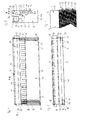
- Fig. 1 is an embodiment of a schematic according to the invention, working according to the induction principle climate convector shown.
- the climate convector has one one-piece, that is, neither in the vertical direction still in the longitudinal direction of housing sections composite, rectangular, preferably made Metal sheets manufactured housing 10, in whose Front side wall 12, a heat exchanger 14 is integrated.
- the heat exchanger 14 is parallel by a small number to side walls 20 of the housing 10 extending lines, symbolize the fins 22 of the heat exchanger 14, shown.
- the heat exchanger 14, by the ambient air U enters the housing 10 forms approximately a lower 3/4 the surface of the front side wall 12.
- the housing 10 has a bead 16 in the form of angled edges with circular recesses 18 for fixing the Klimakonvektors on a substrate, in particular a Wall, or a frame and for attaching panels or other ornamental or protective elements.
- the air distribution box 24 is preferably also out Made of metal sheets and points to his opposite transverse sides cylindrical tube approaches 26th on.
- the Air distribution box 24 about a pivot axis S pivotally in upwardly open U-shaped recesses 28 (FIG. 2) stored in the side walls 20 of the housing 10 and in the desired pivot position fixable.
- the lower curves of the U-shaped recesses 28 in the side walls 20 have a slightly smaller Radius than the tube shoulders 26, so that the fixation of the used in its predetermined pivotal position Heilverteilerkastens 24 by static friction between the Pipe lugs 26 and the curves of the U-shaped Recesses 28 takes place.
- the tube approaches 26 serve the ventilation connection to a fresh air supply system of known type, not shown, via which fresh air F, which is for example under a pre-pressure between about 100Pa and about 400Pa, preferably 200Pa, is supplied to the air conditioning coil.
- the flow rate of fresh air F at an inlet pressure of about 200 Pa is typically m to values between 30 3 / 70m 3 / h and set h.
- the pipe extensions 26 are preferably airtight connected to the environment with flexible hoses, so that, for example, up to five, preferably up to three air conditioning units can be fed in a row. In a single supply of air conditioning convectors with fresh air F is not required for the supply pipe socket 26 is closed with a cover.
- elongated slots 32 arranged in the lower part of a heat exchanger 14 facing Longitudinal side wall 30 of the air distribution box 24.
- elongated slots 32 are nozzles 34, for reasons of clarity only one is shown in Fig. 1, but in more detail in FIG. 2, FIG. 5 and FIG. 6 to FIG. 9 are shown and described in detail later, guided.
- the upper edges of the slots 32 and the nozzles 34 are laterally offset, in the vertical direction below the upper edge of the heat exchanger 14, as shown in FIG Fig. 1 and Fig. 2 can be seen.
- the number of Slots 32 and thus the number of nozzles 32 and the Size of the induction power, ie the ratio of eingpiesener fresh air to the sucked Ambient air amount is the dimensions of the housing 10 and other requirements, including the desired Room climate, adapted.
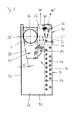
- FIG. 2 located inside the Housing 10 above the heat exchanger 14, in one Distance from the longitudinal side wall 30 an air baffle 36.
- the lying in the interior of the housing 10 lower edge of Air baffle 36 closes almost seamlessly in the Housing 10 lying top of the heat exchanger 14 at.
- the upper edge of the air guide plate 36 extends approximately on the Height of the top edge of the front wall 12.
- the Air guide plate 36 is an axis designated by S ' pivotable.
- Two attached to the air baffle 36 Thread co-operating locking screws 38 which engage the side walls 20 of the housing 10 shaped slots 40, allow a determination of the Air baffle 36 in different pivot positions.
- the Locking screws 38 are also in Fig. 3, a Top view of the climate convector shown in Fig. 1, located.
- the housing 10 has a rectangular cross-section and a rectangular bottom 42 on.
- the area of the bottom 42 is smaller than that in FIG Fig. 1 shown front surface of the Klimakonvektors.
- the floor 42 of the housing 10 forms a sealed container to possibly occurring condensate.
- Fig. 4 is a detail of the front view of Klimakonvektors presented.
- the preferably separate Piping systems of cold water lines 44 and Hot water pipes 46 pass through the fins 22 of the Heat exchanger 14 and are thermally conductive with them connected.
- the cold and hot water lines 44, 46 are preferably of a thermally conductive metal, for example, copper.
- Connecting sheets 48 of Cold and hot water pipes 44, 46 and Line connections 50 of known type are located outside the side walls 20 of the housing 10. Thereby extends well visible in this figure, tightly packed system of slats 22 over the entire Length of the housing 10. This way is a very compact design with smaller external dimensions of the Housing 10 reached.
- the distance between two adjacent fins 22 is shown in FIG Embodiment about 2.5mm.
- All slats 22 of a Heat exchanger 14 are preferably in the same Direction, parallel to the side walls 20 of the housing 10th aligned.
- the heat exchanger 14 is preferably direct mounted in the housing 10, that is, the side walls of Housing 10 serve to hold the package of lamellae 22 via the associated cold and hot water pipe 44, 46.
- the connection sheets 48 and line connections 50 are only after the insertion of the disk pack in the Housing 10 attached.
- the heat exchanger 14 are made completely separate from the housing 10. In the final assembly then the complete heat exchanger 14 in a corresponding recess the housing 10th attached.
- the heat exchanger 14 shown in FIG. 2 comprises 12 rectilinear passage sections of the Cold water pipe 44 and 6 straight through Pipe sections of the hot water pipe 46.
- the Flow temperatures are, for example, for cold water about 14 ° C and for hot water about 35 ° C.
- the control valves are in Generally with a preferably electric Control and regulation unit connected.
- the Control function is generally influenced by a connected temperature sensor.
- the shape of the Air duct 52 influences the flow profile of the mixed convection blast M.
- FIG. 5, which substantially corresponds to FIG. 2, is one Selection of dotted dashed positions the air distribution box 24 and the air baffle 36th added.
- the air distribution box 24 is through his Angled rear wall 54 at an angle of 0 ° to about 10 ° against a rear wall 56 of the housing 10 continuously pivotable about a pivot axis S.
- Correspondingly pans the longitudinal side wall 30 and with it the nozzles 34 to the same angle, so that the fresh air flow at an angle Direction of the top edge of the front wall 12 or straight directed upward parallel to the front side wall 12.
- the pivot axis S of Air distribution box 24 passes centrally through the Pipe shoulders 26 and is almost parallel and on the same Height measured from the bottom 42 of the housing 10, as the Swivel axis S 'of the air baffle 36.
- the air baffle 36 is pivotable about an angle of 30 °.
- the Pivoting of the air baffle 36 can be up to two End positions take place, in which the air guide plate almost aligned parallel to the Fronjobwand 12 or the Top edge of the air baffle 36 with the upper edge of the Front wall 12 is flush.
- the flow profile is in Reduced cross section and thereby receives a reinforced Beam characteristics. Conversely, this widens Flow profile when the air duct 52 through the Pivoting is widened.
- Fig. 6 to Fig. 9 are various views of a inventive nozzle 34 for use in a Climate convector shown.
- the nozzle 34 has a hollow Nozzle body 58 with an oblong-oval inlet opening 60.
- the wall thickness of the nozzle 34 is substantially constant, so that conclusions from the outer to the inner dimensions can be pulled.
- Im in the Air distribution box 24 inserted state is located the inlet opening 60 in the air distribution box 24 and the Nozzle body 58 protrudes through the slots 32 from the Air distribution box 24 in the interior of the housing 10.
- the Nozzles 34 are preferably made of plastic in one Injection molding process.
- the inlet opening 60 of the nozzle 34 is located in a first Level.
- the nozzle 34 also has four Outlet openings 62, at the free ends of four am Nozzle body 58 formed guide tubes 64 formed are.
- the outlet openings 62 are all in one second level, which is perpendicular to the first level.
- the longitudinal axes of the guide tubes 64 are almost parallel to the first level as well as to the first level lying longitudinal axis of the inlet opening 60 and at right angles to the second level.
- the length of the Guide tubes 64 is equal to or less than 1/5 the Longitudinal extent of the inlet opening 60 of the nozzle 34. Bei the embodiment shown, the length of the Guide tubes 64 between 7mm and 12mm, the Longitudinal extent of the inlet opening 60 is 61mm.
- the outer width of the nozzle body 58 that is its Extension perpendicular to its plane of symmetry, which is perpendicular to the first and second plane is smaller, preferably 5 to 20 times smaller than the Longitudinal extent of the inlet opening 60 of the nozzle 34. In the embodiment shown is the outer width between 5mm and 6mm.
- the guide tubes run 64 of the nozzle body 58 outside in the direction of their free End conical and rounded at the free end. There Form the outlet openings 62.
- the outer contour 66 of the nozzle body 58 on the Inlet opening 60 opposite side runs approximately parabolic ( Figures 6 and 9).
- the Nozzle body 58 has no sharp edges on the flow side or corners on, but is both in his inner as well also outer surfaces rounded and with a smooth Surface provided. This will make you almost silent Operation with a sound pressure level less than 29dB (A) at reached a pre-pressure of 300Pa.
- the Exit velocity of the fresh air F is in Dependence of the pre-pressure between 10m / s to 50m / s.
- the geometry of the nozzles 34 is optimized so that at all Outlets almost the same amount of fresh air F emerges with almost the same exit velocity and an induction ratio between 1: 5 to 1:10, Typically, about 1: 7 is achieved.
- the nozzles 34 with the slots 32 of the air distribution box 24th are located on the two side surfaces 68 of the Nozzle body 58 each have a locking groove 70 and one each Latch extension 72 as well as a complete around the Inlet opening 60 circumferential, on the inner surface the longitudinal side wall 30 coming to the plant Sealing flange 74.
- the latching projection 72 is in the form of a Ball part of the side surfaces 68 of the nozzle body 58th path.
- the latching extension 72 has a wedge-shaped cross-section.
- the sealing flange 74 is also on the flow side rounded and has no sharp edges or corners, so that there, too, the passing fresh air F no Sounds or sounds generated.
- the climate convector is preferably used as a sill device for Wall mounting, for example below windows, executed.
- a ceiling mounting is in principle also possible.
- the shape of the housing 10 can both in their Measure as well as in their proportions the respective Installation site to be adjusted.
- the inventive Klimakonvektor enabled by the pivotable air distribution box 24 and the pivotable Air baffle 36 an adjustment and alignment of the Flow profile of the outgoing mixed air M on various conditions of the surrounding space, without that necessarily additional deflecting devices must be attached.
- the climate coil has over it
- a simple structure so that assembly and Cleaning work carried out with little effort can be.
- the inventive Klimakonvektor also has a space-saving construction of the housing 10 as Convectors of known type.
Abstract
Description
- Fig. 1
- eine Vorderansicht eines Klimakonvektors mit einer Anzahl von links und rechts seiner Seitenwände dargestellten Lamellen eines integrierten Wärmetauschers und mit einem mit regelmässig angeordneten Schlitzen versehenen Luftverteilerkasten;
- Fig. 2
- eine Seitenansicht durch den in Fig. 1 gezeigten Klimakonvektor mit zylindrischen Rohransätzen und geschnitten dargestellten Kalt- und Warmwasserleitungen des Wärmetauschers;
- Fig. 3
- eine Draufsicht auf den in Fig. 1 gezeigten Klimakonvektor;
- Fig. 4
- einen Teil der Vorderansicht des in Fig. 1 gezeigten Klimakonvektors mit Kalt- und Warmwasserleitungen sowie Verbindungsbögen und Leitungsanschlüssen;
- Fig. 5
- die bereits in Fig. 2 dargestellte Seitenansicht des Klimakonvektors bei verschiedenen Schwenkstellungen des Luftverteilerkastens und eines Luftleitbleches;
- Fig. 6
- eine Seitenansicht einer Düse für den in Fig. 1 bis Fig. 5 gezeigten Klimakonvektor;
- Fig. 7
- eine Vorderansicht der in Fig. 6 gezeigten Düse mit einer Rastnut, einem Rastvorsprung und einem Dichtungsflansch;
- Fig. 8
- eine Draufsicht auf die in Fig. 6 gezeigte Düse; und
- Fig. 9
- eine perspektivische Ansicht der Düse mit vier aussen angephasten Führungsrohren.
Claims (18)
- Klimakonvektor mit einem Gehäuse (10) zur Aufnahme eines Wärmetauschers (14) und eines mit Frischluft (F) gespiesenen Luftverteilerkastens (24), wobei die Frischluft (F) über an einer Längsseitenwand (30) des Luftverteilerkastens (24) fest angeordnete Düsen (34) in das Gehäuse (10) eingeleitet wird und sich dort mit durch Induktion angesaugter Umgebungsluft, die durch den Wärmetauscher (14) hindurch in das Gehäuse (10) eintritt und dort temperierbar ist, vermischt, um anschliessend geführt von einem Luftleitblech (36) das Gehäuse (10) wieder zu verlassen, dadurch gekennzeichnet, dass der Luftverteilerkasten (24) um eine Schwenkachse (S) schwenkbar im Gehäuse (10) angeordnet und in der gewünschten Schwenklage fixierbar ist.
- Klimakonvektor nach Anspruch 1, dadurch gekennzeichnet, dass das Gehäuse (10) einstückig und quaderförmig ausgebildet ist und eine, vorzugsweise zum Inneren eines zu klimatisierenden Raumes gerichtete Frontseitenwand (12) aufweist, in die der Wärmetauscher (14) integriert ist.
- Klimakonvektor nach einem der Ansprüche 1 oder 2, dadurch gekennzeichnet, dass der Wärmetauscher (14) mindestens eine Hälfte einer Aussenseite des Gehäuses (10), vorzugsweise etwa ein unteres 3/4 der Fläche der Frontseitenwand (12) bildet.
- Klimakonvektor nach einem der Ansprüche 1 bis 3, dadurch gekennzeichnet, dass sich der Wärmetauscher (14) über die gesamte Länge des Gehäuses (10) erstreckt und Verbindungsbögen (48) sowie Leitungsanschlüsse (50) ausserhalb des Gehäuses (10) angeordnet sind.
- Klimakonvektor nach einem der Ansprüche 1 bis 4, dadurch gekennzeichnet, dass der Luftverteilerkasten (24) an seinen gegenüberliegenden Endbereichen seiner Querseiten Rohransätze (26) aufweist, die von U-förmigen, nach oben offenen Ausnehmungen (28) in zwei Seitenwänden (20) des Gehäuses (10) aufgenommen sind.
- Klimakonvektor nach einem der Ansprüche 1 bis 5, dadurch gekennzeichnet, dass das Luftleitblech (36) im Gehäuse (10) schwenkbar um eine parallel zur Schwenkachse (S) des Luftverteilerkastens (24) verlaufende Schwenkachse (S'), gelagert ist und mit der gegenüberliegenden, zum Wärmetauscher (14) hin gerichteten inneren Längsseitenwand (30) des Luftverteilerkastens (24) eine Luftleitkanal (52) bildet, der die Frischluft (F) gemischt mit der temperierten Umgebungsluft in einer gerichteten Strömung aus dem Gehäuse (10) in die Umgebung leitet.
- Klimakonvektor nach einem der Ansprüche 1 bis 6, dadurch gekennzeichnet, dass der Wärmetauscher (14) getrennte Kaltwasserleitungen (44) und Warmwasserleitungen (46) aufweist.
- Klimakonvektor nach einem der Ansprüche 1 bis 7, dadurch gekennzeichnet, dass der Luftverteilerkasten (24) an seiner inneren, zum Wärmetauscher (14) hin gerichteten Längsseitenwand (30) Schlitze (32) für eine rastartige Aufnahme der Düsen (32) aufweist.
- Klimakonvektor nach einem der Ansprüche 1 bis 8, dadurch gekennzeichnet, dass die Düsen (34) einen hohlen Düsenkörper (58) mit einer länglich-ovalen Eintrittsöffnung (60) in einer ersten Ebene und mit einer Anzahl von Austrittsöffnungen (62), welche an freien Enden von am Düsenkörper (58) ausgeformten Führungsrohren (64), deren Länge kleiner als 1/5 der Längsausdehnung der Eintrittsöffnung (60) der Düse (34), gebildet sind, in einer nahezu rechtwinklig zur ersten Ebene und zur in der ersten Ebene liegenden Längsachse der Eintrittsöffnung (60) verlaufenden zweiten Ebene aufweisen.
- Klimakonvektor nach Anspruch 9, dadurch gekennzeichnet, dass die äussere Ausdehnung des Düsenkörpers (58) senkrecht zu seiner Symmetrieebene, die senkrecht zur ersten und zweiten Ebene verläuft, kleiner, vorzugsweise 5 bis 20 mal kleiner als die Längsausdehnung der Eintrittsöffnung (60) der Düse (34) ist.
- Klimakonvektor nach einem der Ansprüche 9 oder 10, dadurch gekennzeichnet, dass die Führungsrohre (64) des Düsenkörpers (58) aussen in Richtung ihres freien Endes konisch zulaufen und am freien Ende abgerundet sind, um dort die Austrittsöffnungen (62) zu formen.
- Klimakonvektor nach einem der Ansprüche 9 bis 11, dadurch gekennzeichnet, dass eine Aussenkontur (66) des Düsenkörpers (58) auf der der Eintrittsöffnung (60) gegenüberliegenden Seite wenigstens annähernd parabelförmig verläuft.
- Klimakonvektor nach einem der Ansprüche 9 bis 12, dadurch gekennzeichnet, dass am Düsenkörper (58) ein die Eintrittsöffnung (60) vollständig umlaufender Dichtungsflansch (74), eine Rastnut (70) und einen Rastfortsatz (72) ausgeformt sind, um eine wenigstens nahezu luftdichte Rastverbindung zwischen dem Luftverteilerkasten (24) und der Düse (34) zu bilden.
- Düse für einen Klimakonvektor mit einem Düsenkörper (58) mit einer länglich-ovalen Eintrittsöffnung (60) in einer ersten Ebene und einer Anzahl von Austrittsöffnungen (62) an freien Enden von am Düsenkörper (58) ausgeformten Führungsrohren (64) in einer nahezu rechtwinklig zur ersten Ebene und zur in der ersten Ebene liegenden Längsachse der Eintrittsöffnung (60) verlaufenden zweiten Ebene, dadurch gekennzeichnet, dass die Länge der Führungsrohre (64) kleiner als 1/5 der Längsausdehnung der Eintrittsöffnung (60) der Düse (34) ist.
- Düse für Klimakonvektor nach Anspruch 14, dadurch gekennzeichnet, dass die äussere Ausdehnung des Düsenkörpers (58) senkrecht zu seiner Symmetrieebene, die senkrecht zur ersten und zweiten Ebene verläuft, kleiner, vorzugsweise 5 bis 20 mal kleiner als die Längsausdehnung der Eintrittsöffnung (60) der Düse (34) ist.
- Düse für Klimakonvektor nach einem der Ansprüche 14 oder 15, dadurch gekennzeichnet, dass die Führungsrohre (64) aussen in Richtung ihres freien Endes konisch zulaufen und am freien Ende abgerundet sind, um dort die Austrittsöffnungen (62) zu formen.
- Düse für Klimakonvektor nach einem der Ansprüche 14 bis 16, dadurch gekennzeichnet, dass eine Aussenkontur (66) des Düsenkörpers (58) auf der der Eintrittsöffnung (60) gegenüberliegenden Seite wenigstens annähernd parabelförmig verläuft.
- Düse für Klimakonvektor nach einem der Ansprüche 14 bis 17, dadurch gekennzeichnet, dass am Düsenkörper (58) ein die Eintrittsöffnung (60) vollständig umlaufender Dichtungsflansch (74), eine Rastnut (70) und einen Rastfortsatz (72) ausgeformt sind.
Priority Applications (1)
| Application Number | Priority Date | Filing Date | Title |
|---|---|---|---|
| EP04000416A EP1553362A1 (de) | 2004-01-12 | 2004-01-12 | Klimakonvektor |
Applications Claiming Priority (1)
| Application Number | Priority Date | Filing Date | Title |
|---|---|---|---|
| EP04000416A EP1553362A1 (de) | 2004-01-12 | 2004-01-12 | Klimakonvektor |
Publications (1)
| Publication Number | Publication Date |
|---|---|
| EP1553362A1 true EP1553362A1 (de) | 2005-07-13 |
Family
ID=34585971
Family Applications (1)
| Application Number | Title | Priority Date | Filing Date |
|---|---|---|---|
| EP04000416A Withdrawn EP1553362A1 (de) | 2004-01-12 | 2004-01-12 | Klimakonvektor |
Country Status (1)
| Country | Link |
|---|---|
| EP (1) | EP1553362A1 (de) |
Citations (4)
| Publication number | Priority date | Publication date | Assignee | Title |
|---|---|---|---|---|
| GB1477857A (en) * | 1973-06-06 | 1977-06-29 | Luwa Ag | Air-conditioning apparatus |
| DE3913306A1 (de) * | 1989-04-22 | 1990-10-25 | Gravivent Raumlufttechnik Gmbh | Vorrichtung zum klimatisieren von raeumen |
| DE10007452A1 (de) * | 1999-02-19 | 2000-08-31 | Halton Oy | Zuluftvorrichtung |
| DE10142983A1 (de) * | 2001-09-01 | 2003-03-27 | Krantz Tkt Gmbh I Ins | Deckenkonvektor |
-
2004
- 2004-01-12 EP EP04000416A patent/EP1553362A1/de not_active Withdrawn
Patent Citations (4)
| Publication number | Priority date | Publication date | Assignee | Title |
|---|---|---|---|---|
| GB1477857A (en) * | 1973-06-06 | 1977-06-29 | Luwa Ag | Air-conditioning apparatus |
| DE3913306A1 (de) * | 1989-04-22 | 1990-10-25 | Gravivent Raumlufttechnik Gmbh | Vorrichtung zum klimatisieren von raeumen |
| DE10007452A1 (de) * | 1999-02-19 | 2000-08-31 | Halton Oy | Zuluftvorrichtung |
| DE10142983A1 (de) * | 2001-09-01 | 2003-03-27 | Krantz Tkt Gmbh I Ins | Deckenkonvektor |
Similar Documents
| Publication | Publication Date | Title |
|---|---|---|
| EP2366082B1 (de) | Luftdurchlass mit einem gehäuse sowie ein deckensegel mit luftdurchlass | |
| EP3327366A1 (de) | Luftauslass zum temperieren eines raumes | |
| EP3168545B1 (de) | Luftschleieranlage | |
| DE102008005364A1 (de) | Unterflurkonvektor | |
| DE102008042803C5 (de) | Vorrichtung zur Führung eines Luftstromes | |
| DE2328186C2 (de) | Induktionsgerät | |
| EP1462730A1 (de) | Vorrichtung zur Erzeugung eines Luftschleiers | |
| DE19525945C2 (de) | Verfahren und Vorrichtung zur Erzeugung behaglicher Raumluftzustände | |
| CH691621A5 (de) | Mattenartiger Wärmetauscher für Kühl- und/oder Heizzwecke. | |
| EP2573475B1 (de) | Als Induktionsgerät ausgebildetes lufttechnisches Gerät sowie Verfahren zum Betreiben des Geräts | |
| EP0715129B1 (de) | Sockelquellauslass | |
| DE4210279A1 (de) | Quelluftdurchlaß für raumlufttechnische Anlagen | |
| EP1553362A1 (de) | Klimakonvektor | |
| DE2033195B2 (de) | Luftaustrittseinrichtung für Klimaanlagen | |
| EP2752318A1 (de) | Kraftfahrzeug mit einem Wasserkasten | |
| EP3587943A2 (de) | Vorrichtung zur belüftung und temperierung eines raums eines gebäudes | |
| WO2020161565A1 (de) | System zur belüftung von räumen | |
| EP1996870A1 (de) | Bodenkonvektor | |
| EP1162411B1 (de) | Luftwärme/Klimagerät | |
| DE3025342A1 (de) | Vorrichtung zur belueftung von arbeitsraeumen, insbesondere von fabrikhallen | |
| DE202016102068U1 (de) | Luftleitblende und Deckenkassette mit Luftleitblende | |
| DE1679539A1 (de) | Verteilkanal fuer uebersaettigte Luft von einer Lueftungs- und Klimaanlage | |
| DE10016931C2 (de) | Luftauslass | |
| DE102007052205B4 (de) | Luftauslassdüse für eine Trennstrahlanlage und Düsenstrang | |
| DE1105587B (de) | Luftkanal fuer Lueftungsanlagen |
Legal Events
| Date | Code | Title | Description |
|---|---|---|---|
| PUAI | Public reference made under article 153(3) epc to a published international application that has entered the european phase |
Free format text: ORIGINAL CODE: 0009012 |
|
| AK | Designated contracting states |
Kind code of ref document: A1 Designated state(s): AT BE BG CH CY CZ DE DK EE ES FI FR GB GR HU IE IT LI LU MC NL PT RO SE SI SK TR |
|
| AX | Request for extension of the european patent |
Extension state: AL LT LV MK |
|
| 17P | Request for examination filed |
Effective date: 20060113 |
|
| AKX | Designation fees paid |
Designated state(s): AT BE BG CH CY CZ DE DK EE ES FI FR GB GR HU IE IT LI LU MC NL PT RO SE SI SK TR |
|
| 17Q | First examination report despatched |
Effective date: 20071113 |
|
| STAA | Information on the status of an ep patent application or granted ep patent |
Free format text: STATUS: THE APPLICATION IS DEEMED TO BE WITHDRAWN |
|
| 18D | Application deemed to be withdrawn |
Effective date: 20080326 |