EP1553045A1 - Modular labelling device - Google Patents
Modular labelling device Download PDFInfo
- Publication number
- EP1553045A1 EP1553045A1 EP05004404A EP05004404A EP1553045A1 EP 1553045 A1 EP1553045 A1 EP 1553045A1 EP 05004404 A EP05004404 A EP 05004404A EP 05004404 A EP05004404 A EP 05004404A EP 1553045 A1 EP1553045 A1 EP 1553045A1
- Authority
- EP
- European Patent Office
- Prior art keywords
- machine according
- carousel
- elements
- table top
- labeling
- Prior art date
- Legal status (The legal status is an assumption and is not a legal conclusion. Google has not performed a legal analysis and makes no representation as to the accuracy of the status listed.)
- Withdrawn
Links
Images


Classifications
-
- B—PERFORMING OPERATIONS; TRANSPORTING
- B67—OPENING, CLOSING OR CLEANING BOTTLES, JARS OR SIMILAR CONTAINERS; LIQUID HANDLING
- B67C—CLEANING, FILLING WITH LIQUIDS OR SEMILIQUIDS, OR EMPTYING, OF BOTTLES, JARS, CANS, CASKS, BARRELS, OR SIMILAR CONTAINERS, NOT OTHERWISE PROVIDED FOR; FUNNELS
- B67C7/00—Concurrent cleaning, filling, and closing of bottles; Processes or devices for at least two of these operations
- B67C7/0006—Conveying; Synchronising
- B67C7/002—General lay-out of bottle-handling machines
-
- B—PERFORMING OPERATIONS; TRANSPORTING
- B65—CONVEYING; PACKING; STORING; HANDLING THIN OR FILAMENTARY MATERIAL
- B65C—LABELLING OR TAGGING MACHINES, APPARATUS, OR PROCESSES
- B65C9/00—Details of labelling machines or apparatus
-
- B—PERFORMING OPERATIONS; TRANSPORTING
- B65—CONVEYING; PACKING; STORING; HANDLING THIN OR FILAMENTARY MATERIAL
- B65C—LABELLING OR TAGGING MACHINES, APPARATUS, OR PROCESSES
- B65C9/00—Details of labelling machines or apparatus
- B65C9/0062—Interchangeable modules, e.g. applicator heads with label magazines and glue rollers
-
- B—PERFORMING OPERATIONS; TRANSPORTING
- B65—CONVEYING; PACKING; STORING; HANDLING THIN OR FILAMENTARY MATERIAL
- B65C—LABELLING OR TAGGING MACHINES, APPARATUS, OR PROCESSES
- B65C9/00—Details of labelling machines or apparatus
- B65C9/02—Devices for moving articles, e.g. containers, past labelling station
-
- B—PERFORMING OPERATIONS; TRANSPORTING
- B67—OPENING, CLOSING OR CLEANING BOTTLES, JARS OR SIMILAR CONTAINERS; LIQUID HANDLING
- B67C—CLEANING, FILLING WITH LIQUIDS OR SEMILIQUIDS, OR EMPTYING, OF BOTTLES, JARS, CANS, CASKS, BARRELS, OR SIMILAR CONTAINERS, NOT OTHERWISE PROVIDED FOR; FUNNELS
- B67C7/00—Concurrent cleaning, filling, and closing of bottles; Processes or devices for at least two of these operations
- B67C7/0006—Conveying; Synchronising
- B67C7/004—Conveying; Synchronising the containers travelling along a circular path
- B67C7/0046—Infeed and outfeed devices
-
- F—MECHANICAL ENGINEERING; LIGHTING; HEATING; WEAPONS; BLASTING
- F16—ENGINEERING ELEMENTS AND UNITS; GENERAL MEASURES FOR PRODUCING AND MAINTAINING EFFECTIVE FUNCTIONING OF MACHINES OR INSTALLATIONS; THERMAL INSULATION IN GENERAL
- F16D—COUPLINGS FOR TRANSMITTING ROTATION; CLUTCHES; BRAKES
- F16D3/00—Yielding couplings, i.e. with means permitting movement between the connected parts during the drive
- F16D3/80—Yielding couplings, i.e. with means permitting movement between the connected parts during the drive in which a fluid is used
-
- F—MECHANICAL ENGINEERING; LIGHTING; HEATING; WEAPONS; BLASTING
- F16—ENGINEERING ELEMENTS AND UNITS; GENERAL MEASURES FOR PRODUCING AND MAINTAINING EFFECTIVE FUNCTIONING OF MACHINES OR INSTALLATIONS; THERMAL INSULATION IN GENERAL
- F16F—SPRINGS; SHOCK-ABSORBERS; MEANS FOR DAMPING VIBRATION
- F16F15/00—Suppression of vibrations in systems; Means or arrangements for avoiding or reducing out-of-balance forces, e.g. due to motion
- F16F15/10—Suppression of vibrations in rotating systems by making use of members moving with the system
- F16F15/16—Suppression of vibrations in rotating systems by making use of members moving with the system using a fluid or pasty material
- F16F15/161—Suppression of vibrations in rotating systems by making use of members moving with the system using a fluid or pasty material characterised by the fluid damping devices, e.g. passages, orifices
-
- Y—GENERAL TAGGING OF NEW TECHNOLOGICAL DEVELOPMENTS; GENERAL TAGGING OF CROSS-SECTIONAL TECHNOLOGIES SPANNING OVER SEVERAL SECTIONS OF THE IPC; TECHNICAL SUBJECTS COVERED BY FORMER USPC CROSS-REFERENCE ART COLLECTIONS [XRACs] AND DIGESTS
- Y10—TECHNICAL SUBJECTS COVERED BY FORMER USPC
- Y10T—TECHNICAL SUBJECTS COVERED BY FORMER US CLASSIFICATION
- Y10T156/00—Adhesive bonding and miscellaneous chemical manufacture
- Y10T156/17—Surface bonding means and/or assemblymeans with work feeding or handling means
- Y10T156/1702—For plural parts or plural areas of single part
- Y10T156/1744—Means bringing discrete articles into assembled relationship
- Y10T156/1768—Means simultaneously conveying plural articles from a single source and serially presenting them to an assembly station
- Y10T156/1771—Turret or rotary drum-type conveyor
-
- Y—GENERAL TAGGING OF NEW TECHNOLOGICAL DEVELOPMENTS; GENERAL TAGGING OF CROSS-SECTIONAL TECHNOLOGIES SPANNING OVER SEVERAL SECTIONS OF THE IPC; TECHNICAL SUBJECTS COVERED BY FORMER USPC CROSS-REFERENCE ART COLLECTIONS [XRACs] AND DIGESTS
- Y10—TECHNICAL SUBJECTS COVERED BY FORMER USPC
- Y10T—TECHNICAL SUBJECTS COVERED BY FORMER US CLASSIFICATION
- Y10T74/00—Machine element or mechanism
- Y10T74/14—Rotary member or shaft indexing, e.g., tool or work turret
Definitions
- the invention relates to a machine for equipping Articles (bottles, cans or the like.) According to the preamble of claim 1 or 22nd
- the invention has the object, a simple and inexpensive machine to equip Specify articles that have high flexibility and good Has accessibility.
- the separately arranged rotary bearing of the carousel can be replaced by a table-like frame construction are formed and possibly inclined surfaces for improved liquid and Have dirt dissipation, thereby cleaning the machine is relieved.
- the outer contour of the table-like Frame construction smaller than the outer one Periphery of the carousel and does not tower over it radial direction.
- This is a good accessibility to Carousel ensured. Only the carousel at least partially (from the article to the Article outlet) surrounding ring towers over the carousel in a lower plane in the radial direction slightly, whereby advantageously straight supports for holding Machine parts, such as protective panels, Anbürst Economics or Like. Without ground contact directly placed on the ring and can be attached at any time detachable and adjustable.
- This ring is also available on freestanding labeling can be specified in any circumferential position. This advantage comes even then to bear, if the o.g. frame construction of the carousel and the table top for the transport elements integrally formed or these insoluble with each other are connected.
- the equipment machine has a carousel 1, which in Fig. 1 is indicated only with its pitch circle and several in even pitch intervals arranged turntable. 2 having. Furthermore, an inlet wheel 3 and a Outlet star wheel 4 available, whose subcircles in each case the Touch the circle of the carousel 1. Both star wheels 3 and 4 are for the sake of clarity in Fig. 1 also only indicated by their constituencies.
- At the carousel 1 pioneering side of the star wheels 3 and 4 is located whose sub-circles tangential, rectilinear conveyor belt 5, to the side in the area in front of the inlet stator 3 a parallel aligned Einteilschnecke 6 is arranged.
- the Partial screw 6, the conveyor belt 5 and the star wheels 3, 4 are arranged on a common tabletop 7 stored.
- the star wheels 3, 4 are over vertical waves with the table top 7 rotatably mounted, one with the Sternradteil Vietnameseen matching pitch circle diameter having gear wheels 3 ', 4' rotationally in connection, the in turn with the drive gear 10 of a electromotive machine main drive 20, e.g. one variable speed asynchronous motor with reduction gear, comb.
- a electromotive machine main drive 20 e.g. one variable speed asynchronous motor with reduction gear, comb.
- Coaxial with the drive gear 10 is a with this rotationally connected toothed belt wheel 10 'is arranged, the via a toothed belt 17 with a drive for the carousel 1 serving timing pulley 16 is engaged.
- the drive the Einteilschnecke 6 and possibly also the conveyor belt.
- a vertical center shaft 1c 1 'of the carousel 1 is received by a pivot bearing 11, the stand next to the table top 7 separately for themselves is arranged.
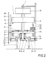
- This a table-like frame 12 having pivot bearing 11 is best in Fig. 2 recognizable.
- the Central shaft 1c is rotationally fixed via a at its lower end attached toothed belt wheel 16 drivable.
- a turntable 1a On the central shaft 1c is inter alia a turntable 1a and an arranged above it, possibly height-adjustable upper part 1b of the carousel 1 mounted rotationally.
- Each turntable 2 is one in the top 1b of the carousel 1 can be raised and lowered centering 8th assigned in a known manner by a not shown control cam is actuated.
- a fixed frame Torque arm 9 To the control curve to secure against turning, is a fixed frame Torque arm 9 available.
- the frame 12 of the pivot bearing 11 with the table top 7 by two the existing space bridging struts 21 connected, in particular solvable, for example by screwing, dowel pins or others suitable elements.
- the connection is made easier by the height-equal arrangement of the table top 7 and the table top 14 of the frame 12, both horizontally with level Surface are formed.
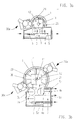
- the base 31 of a Labeling unit on its side facing the ring 23 a Square tube with holes 29a and offset below lying, the ring 23 towards open V-shaped insertion bevels 29b on.
- This detailed view marked X is from below seen shown.
- the base frame 31 for hanging on the Pins 29 are raised so far that the holes 29a above, the insertion bevels 29b but below the upper end of the pins 29 are located.
- the chamfers 29b By radial Approaching the pins 29 center the chamfers 29b the base frame 31 to the holes 29a with the pins 29 are aligned axially. In this position, the holes 29 a by lowering the lower frame 31 with the pins 29th be positively engaged.
- the exact height and tilt is by individually height adjustable feet on Underframe 31 adjustable.
- a protective plate 26 'attached On the base 31 is also on the carousel 1 pointing side a protective plate 26 'attached, whose Outer contour on a cutout in a carousel circumferentially surrounding protective plate 26 is adapted. Also on the side facing the carousel 1 can not illustrated pressing elements (sponge railing, rollers or Brush body) for molding labels to the bottles 40th or the like. Be attached to the base frame 31, in particular - seen from the carousel 1 in front of the protective plate 26 '.
- characterized in a change of a Labeling automatically always to the respective Bottle contour matching pressure elements provided.
- the labeling unit is in Fig. 4 not shown.
- the ring 23 also acts as a support for perpendicular to it standing supports 24, 25, wherein supports 24 as Holder for the carousel 1 circumferentially surrounding Protective disks serve 26, the lifting and along the supports 24 lowered, and supports 25, which serve as a holder for outer brush body 35 for painting labels on the Bottle contour are provided.
- supports 24 as Holder for the carousel 1 circumferentially surrounding Protective disks serve 26, the lifting and along the supports 24 lowered, and supports 25, which serve as a holder for outer brush body 35 for painting labels on the Bottle contour are provided.
- For mounting inside Brush body 36 is on the turntable 1a a support plate 37th stored and secured against twisting.
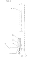
- the supports 24, 25 have at their lower ends to the inclined surface 23 a of the Rings 23 form fitting matching oblique milling on, so that these in the axial and radial direction to the ring 23rd aligned and by an engaging in the groove 23 b, in one attached to the lower end of the supports, the ring Under clamping plate 27 held clamping screw 28 or other releasable attachment radially and axially fixed are.
- the already mentioned torque arm 9 can in the same way be secured against rotation on the ring 23 (see Fig. 5).
- the labeling units 30 each have their own Base frame 31, which may be designed to be movable with wheels can be.
- the base 31 has a the Labeling 30 carrying plate and a housing, in an electromotive drive 32 with its associated Control 34 is housed.
- This controller 34 is so configured to drive the labeling unit 30 fair, i. Position and speed synchronous to continuous rotational movement of the carousel 1 below regulates.
- the drive 32 may be a frequency-controlled Asynchronous motor with a rotary encoder 33 for feedback feedback be to the controller 34.
- At the carousel 1 is a serving as a setpoint encoder rotary encoder 38, the at a Rotation of the carousel 1 by a pitch of two adjacent turntable 2, for example 5000 cycles or Pulses to the input of the controller 34 of the unit drive 32 supplies, whereby one with a predefinable Transmission ratio angle of rotation accurate, regulated Synchronization between a labeling 30 and the Carousel 1 is feasible.
- Each labeling unit 30 can with quick-release connectors for energy and Compressed air supply and signal transmission to be equipped.
- a carousel 1 can be arbitrarily with differently designed input and output Outlet configurations are combined.
- a carousel 1 For example, a table top 7 with two star wheels 3, 4 for a straight, aligned in a conveying direction extending bottle transport 5 (Fig. 3a), or a Table top 7 with three or more star wheels 3a, 3b, 4a, 4b for an angular (Fig. 3c) or parallel, possibly opposite bottle transport 5a, 5b, 5c (FIG. 3b) be provided.
- the advantage of having a change to an existing one Plant layouts of a bottle filling line the Equipment machine by replacing the table top 7 or of the entire entry and exit area and addition of a new plate with further use of the carousel 1 and the Labeling units without purchase of a new machine is flexibly adaptable.
- It can be any Nassleimetiketieraggregate 30a, Rollenetikettieraggregate 30b and Dispensing units 30c for self-adhesive labels combined or be replaced.
- the wet glue labeling units 30a can according to DE 197 41 476 A1, i. with rotating or oscillating adhesive surfaces for label removal, be educated. Each of these adhesive surfaces may possibly by its own programmable electric motor drive be operated.
Landscapes
- Engineering & Computer Science (AREA)
- General Engineering & Computer Science (AREA)
- Mechanical Engineering (AREA)
- Physics & Mathematics (AREA)
- Acoustics & Sound (AREA)
- Aviation & Aerospace Engineering (AREA)
- Labeling Devices (AREA)
- Holo Graphy (AREA)
- Specific Conveyance Elements (AREA)
- Soil Working Implements (AREA)
- Transition And Organic Metals Composition Catalysts For Addition Polymerization (AREA)
- Steroid Compounds (AREA)
- Auxiliary Devices For And Details Of Packaging Control (AREA)
Abstract
Description
Die Erfindung betrifft eine Maschine zum Ausstatten von
Artikeln (Flaschen, Dosen oder dgl.) gemäß dem Oberbegriff
des Anspruchs 1 bzw. 22.The invention relates to a machine for equipping
Articles (bottles, cans or the like.) According to the preamble
of
Bei konventionell ausgeführten Etikettiermaschinen befinden sich alle wesentlichen Baugruppen (Karussell, Transportelemente, Etikettieraggregate usw.) auf einer großen gemeinsamen Tischplatte, die sozusagen die Maschinenbasis bildet. Ungünstig ist die raumgreifende Bauweise und schlechte Zugänglichkeit zu den einzelnen Baugruppen, was Wartungs- und Reinigungsarbeiten erschwert.Located on conventionally designed labeling machines all essential components (carousel, Transport elements, labeling units, etc.) on a large common tabletop, which, so to speak, the machine base forms. Unfavorable is the expansive construction and poor accessibility to the individual assemblies, what Maintenance and cleaning difficult.
Durch DE 31 34 661 A1 wurde bereits vorgeschlagen, ein mittenfreies Behandlungskarussell zusammen mit den Transportelementen zum Zu- und Abführen der Artikel sowie den Etikettieraggregaten auf einer verkürzten Tischplatte zu lagern (Fig. 3). Trotz der vorgeschlagenen verkürzung ist die verbleibende Tischplatte immer noch verhältnismäßig groß und aufwändig. Hauptnachteil ist jedoch die - wie bei den meisten konventionell ausgeführten Etikettiermaschinen - fehlende Flexibilität in Bezug auf spätere Änderungen der Maschinenkonfiguration. Diese sind in der Regel mit einem erheblichen Aufwand verbunden, so dass häufig eine neue Maschine kostengünstiger ist als ein tiefgreifender Umbau einer bestehenden Maschine. DE 31 34 661 A1 has already been proposed, a mid-free treatment carousel along with the Transport elements for feeding and discharging the article and the Labeling units on a shortened table top too store (Fig. 3). Despite the proposed shortening is the remaining tabletop still relatively large and consuming. The main drawback, however, is - as with most conventional labeling machines - missing Flexibility with regard to later changes in the Machine configuration. These are usually with one considerable effort, so often a new one Machine is cheaper than a profound conversion an existing machine.
Aus DE 197 41 476 A1 ist ferner bekannt, bei einer Etikettiermaschine das Behandlungskarussell, die Transportelemente zum Zu- und Abführen der zu etikettierenden Artikel sowie die Etikettieraggregate anstelle auf einer gemeinsamen Tischplatte (Fig. 1) jeweils separat auf eigenen Untergestellen (Fig. 4) anzuordnen. Dieses System bietet im Hinblick auf eine flexible Modulbauweise für den Benutzer vorteile, wenn alle zuvor genannten Elemente der Maschine jeweils durch einen eigenen motorischen Antrieb beaufschlagbar sind, verursacht aber einen erhöhten antriebstechnischen Aufwand.From DE 197 41 476 A1 is also known in a Labeling machine the treatment carousel, the Transport elements for feeding and discharging the to be labeled Article as well as the labeling units instead of on one common tabletop (Fig. 1) each separately on their own To arrange underframes (Fig. 4). This system offers in In view of a flexible modular design for the user advantages, if all the aforementioned elements of the machine each with its own motor drive can be acted upon, but causes an increased drive engineering effort.
Demgegenüber liegt der Erfindung die Aufgabe zugrunde, eine einfache und kostengünstige Maschine zum Ausstatten von Artikeln anzugeben, die eine hohe Flexibilität und gute Zugänglichkeit aufweist.In contrast, the invention has the object, a simple and inexpensive machine to equip Specify articles that have high flexibility and good Has accessibility.
Gelöst wird diese Aufgabe durch die kennzeichnenden Merkmale
des Anspruchs 1 bzw. 22.This problem is solved by the characterizing features
of
Dadurch, dass nur die die Artikel zum Karussell zu- und abführenden Transportelemente (Einlauf-, Auslaufsternräder, Einteilschnecke, Förderbänder) auf einer gemeinsamen Tischplatte gelagert sind, kann diese vorteilhafterweise sehr kompakt gehalten werden, wobei die Antriebselemente (Motor, Zahnräder, Zugmittelgetriebe, Wellen oder dgl.) günstiger Weise an der Unterseite der Tischplatte befestigbar sind, während das eigentliche Karussell zur Behandlung der Artikel beim Ausstattungsvorgang mit seinem Drehlager außerhalb der Tischplatte separat für sich auf einem eigenen Traggestell angeordnet ist.The fact that only the articles to the carousel and discharging transport elements (inlet and outlet star wheels, One-section screw, conveyor belts) on a common Table top are stored, this can be very beneficial be kept compact, wherein the drive elements (engine, Gears, traction drives, shafts or the like.) Less expensive Way attachable to the bottom of the table top, while the actual carousel is for the treatment of the article in the equipment process with its pivot outside the Tabletop separately on its own support frame is arranged.
Diese Lösung erlaubt die Realisierung eines kostengünstigen Antriebssystems für die Transportelemente mit nur einem motorischen Antrieb, während die Weiterverzweigung der Kraftübertragung in erwähnter Weise durch mechanische Elemente erfolgt. Zugleich ist eine gute Zugänglichkeit des freistehenden Behandlungskarussells und der einzelnen ebenfalls freistehenden Etikettieraggregate gegeben, die am Umfang des Karussells an beliebigen Positionen in Abhängigkeit der gewünschten Ausstattungsvarianten platzierbar sind. Diese Etikettieraggregate können unterschiedlicher Ausführung (Nassleim-Aggregat, Heißleim-Aggregat, Spende-Aggregat für Selbstklebeetiketten, Etikettieraggregat für Rollenetiketten oder dgl.) sein und jeweils über ein eigenes Untergestell, ggf. auch über jeweils mindestens einen eigenen motorischen Antrieb verfügen.This solution allows the realization of a cost-effective Drive system for the transport elements with only one motor drive, while the branching of the Power transmission in the manner mentioned by mechanical Elements takes place. At the same time, good accessibility of the freestanding treatment carousel and the individual also freestanding labeling units given on Circumference of the carousel at any position in Dependence of the desired equipment variants are placeable. These labeling units can different version (wet glue aggregate, hot melt aggregate, Dispensing unit for self-adhesive labels, Labeling unit for roll labels or the like) and each with its own base, possibly also each have at least one own motor drive.
An der Peripherie des Karussells sind Elemente zur Festlegung der relativen Lage der Etikettieraggregate, der Anbürstelemente und noch weiterer Maschinenbauteile zum Karussell vorhanden, die neben dem radialen Abstand auch die Höhe, Neigung und die Position am Umfang des Karussells bestimmen. Eine umständliche und ungenaue Befestigung der genannten Bauteile am Hallenboden zur Fixierung der Relativpositionen ist damit entbehrlich. Hierfür sind horizontale, ggf. in Umfangsrichtung verstellbare Ausleger am Drehlager bzw.Gestell des Karussells geeignet. Günstig ist insbesondere eine an den Karussellumfang angepaßte ringförmige Elementausführung, weil damit beliebige, stufenlose Umfangspositionierungen einfach realisierbar sind. Diese Lösung ermöglicht einen schnellen Wechsel der Etikettieraggregate und ggf. weiterer Formatteile, wie Anbürstelemente oder dgl. beim Benutzer einer Maschine, wenn eine Umstellung auf eine andere Ausstattung oder Flaschengröße erfolgen soll, insbesondere in Verbindung mit voreingestellten Wechselkupplungselementen, die eine schnelle und exakte Selbstzentrierung der entsprechenden Bauteile gewährleisten. At the periphery of the carousel are elements for fixing the relative position of the labeling units, the Brushing elements and other machine components for Carousel available, in addition to the radial distance and the Height, inclination and position on the circumference of the carousel determine. A cumbersome and inaccurate attachment of the mentioned components on the hall floor for fixing the Relative positions is thus unnecessary. For this are horizontal, possibly in the circumferential direction adjustable boom on Rotary or Gestell of the carousel suitable. Cheap is in particular adapted to the carousel circumference ring-shaped element design, because with it any, Continuously variable circumferential positioning can be easily realized. This solution allows a quick change of Labeling units and possibly other format parts, such as Brushing elements or the like. At the user of a machine, if a conversion to another equipment or Bottle size to be made, especially in conjunction with preset change coupling elements that provide a fast and exact self-centering of the corresponding components guarantee.
Auf Grund dieses Konzepts ist neben der hervorragenden Zugänglichkeit eine hohe Flexibilität für den Benutzer der Maschine und eine Vereinfachung der Herstellung und Montage für den Hersteller der Maschine durch die einzelnen Maschinenmodule gegeben, die bei Bedarf wechselbar bzw. individuell kombinierbar sind.Because of this concept is next to the excellent Accessibility a high degree of flexibility for the user of Machine and a simplification of manufacture and assembly for the manufacturer of the machine by the individual Machine modules given, which can be changed as needed or individually combinable.
Das separat stehende Drehlager des Karussells kann durch eine tischartige Gestellkonstruktion gebildet werden und ggf. geneigte Oberflächen zur verbesserten Flüssigkeits- und Schmutzableitung besitzen, wodurch die Reinigung der Maschine erleichtert wird.The separately arranged rotary bearing of the carousel can be replaced by a table-like frame construction are formed and possibly inclined surfaces for improved liquid and Have dirt dissipation, thereby cleaning the machine is relieved.
Günstigerweise ist die Außenkontur der tischartigen Gestellkonstruktion kleiner ausgeführt als die äußere Peripherie des Karussells und überragt diese nicht in radialer Richtung. Dadurch ist eine gute Zugänglichkeit zum Karussell sichergestellt. Lediglich ein das Karussell zumindest teilumfänglich (vom Artikelein- bis zum Artikelauslauf) umgebender Ring überragt das Karussell in einer tieferliegenden Ebene in radialer Richtung geringfügig, wodurch vorteilhafterweise gerade Stützen zum Halten von Maschinenteilen, wie Schutzverkleidungen, Anbürstkörper oder dgl. ohne Bodenkontakt direkt auf den Ring gestellt und jederzeit lös- und verstellbar befestigt werden können. An diesem Ring sind auch freistehende Etikettieraggregate an beliebigen Umfangspositionen festlegbar. Dieser Vorteil kommt auch dann noch zum Tragen, wenn die o.g. Gestellkonstruktion des Karussells und die Tischplatte für die Transportelemente einstückig ausgebildet oder diese unlösbar miteinander verbunden sind.Conveniently, the outer contour of the table-like Frame construction smaller than the outer one Periphery of the carousel and does not tower over it radial direction. This is a good accessibility to Carousel ensured. Only the carousel at least partially (from the article to the Article outlet) surrounding ring towers over the carousel in a lower plane in the radial direction slightly, whereby advantageously straight supports for holding Machine parts, such as protective panels, Anbürstkörper or Like. Without ground contact directly placed on the ring and can be attached at any time detachable and adjustable. At This ring is also available on freestanding labeling can be specified in any circumferential position. This advantage comes even then to bear, if the o.g. frame construction of the carousel and the table top for the transport elements integrally formed or these insoluble with each other are connected.
Weitere vorteilhafte Ausgestaltungen sind Gegenstand der verbleibenden Unteransprüche. Further advantageous embodiments are the subject of remaining subclaims.
Nachfolgend wird ein bevorzugtes Ausführungsbeispiel anhand der Fig. erläutert. Es zeigt:
- Fig. 1
- eine Draufsicht einer Ausstattungsmaschine in schematischer Darstellung,
- Fig. 2
- eine Seitenansicht des Karussells der Ausstattungsmaschine nach Fig. 1 in teilweiser Schnittdarstellung,
- Fig. 3a bis 3c
- mehrere Varianten einer Ausstattungsmaschine in schematischer Draufsicht,
- Fig.4
- ein Untergestell eines Etikettieraggregats in vergrößerter Darstellung und
- Fig. 5
- ein Detail der Ausstattungsmaschine aus Fig. 2 in vergrößerter Abbildung.
- Fig. 1
- a top view of an equipment machine in a schematic representation,
- Fig. 2
- 3 is a side view of the carousel of the equipment machine of FIG. 1 in a partial sectional view,
- Fig. 3a to 3c
- several variants of an equipment machine in a schematic plan view,
- Figure 4
- a base of a labeling in an enlarged view and
- Fig. 5
- a detail of the equipment machine of Fig. 2 in an enlarged illustration.
Die Ausstattungsmaschine besitzt ein Karussell 1, das in Fig.
1 nur mit seinem Teilkreis angedeutet ist und mehrere in
gleichmäßigen Teilungsabständen angeordnete Drehteller 2
aufweist. Des weiteren sind ein Einlaufsternrad 3 und ein
Auslaufsternrad 4 vorhanden, deren Teilkreise jeweils den
Teilkreis des Karussells 1 berühren. Beide Sternräder 3 und 4
sind zwecks der besseren Übersicht in Fig. 1 ebenfalls nur
durch ihre Teilkreise angedeutet. An der vom Karussell 1
wegweisenden Seite der Sternräder 3 und 4 befindet sich ein
deren Teilkreise tangierendes, geradliniges Förderband 5, an
dem seitlich im Bereich vor dem Einlaufsternrad 3 eine
parallel ausgerichtete Einteilschnecke 6 angeordnet ist. Die
Einteilschnecke 6, das Förderband 5 und die Sternräder 3, 4
sind auf einer gemeinsamen Tischplatte 7 angeordnet bzw.
gelagert.The equipment machine has a
Die Sternräder 3, 4 stehen über vertikale Wellen mit unter
der Tischplatte 7 drehbar gelagerten, einen mit den
Sternradteilkreisen übereinstimmende Teilkreisdurchmesser
aufweisenden Zahnrädern 3', 4' verdrehfest in verbindung, die
ihrerseits mit dem Antriebszahnrad 10 eines
elektromotorischen Maschinenhauptantriebs 20, z.B. ein
drehzahlregelbarer Asynchronmotor mit Untersetzungsgetriebe,
kämmen. Koaxial zum Antriebszahnrad 10 ist ein mit diesem
verdrehfest verbundenes Zahnriemenrad 10' angeordnet, das
über einen Zahnriemen 17 mit einem zum Antrieb des Karussells
1 dienenden Zahnriemenrad 16 in Eingriff steht. Der Antrieb
der Einteilschnecke 6 sowie ggf. auch des Förderbands 5
erfolgt durch im Detail nicht gezeigte mechanische
Kraftübertragungselemente (Zahnräder, Zahnriemen und
Gelenkwellen) über eines der vorgenannten Zahnräder vom
Maschinenhauptantrieb 20 aus. Es versteht sich, dass der
Maschinenhauptantrieb alternativ auch direkt dem Karussell 1
zugeordnet werden könnte, oder sowohl der Tisch 7 als auch
das Karussell 1 jeweils einen eigenen Motor erhalten könnten,
die zueinander synchronisiert sind, wobei dann der Zahnriemen
17 entbehrlich wäre.The
Die durch eine vertikale Mittelwelle 1c gebildete Drehachse
1' des Karussells 1 wird von einem Drehlager 11 aufgenommen,
das neben der Tischplatte 7 separat für sich stehend
angeordnet ist. Dieses ein tischartig ausgebildetes Gestell
12 aufweisende Drehlager 11 ist am besten in Fig. 2
erkennbar. Wie dort dargestellt, trägt das auf Stützfüßen 15
stehende Gestell 12 in einer angeformten oder aufgesetzten,
innen hohlen Lagersäule 13 die Mittelwelle 1c. Die
Mittelwelle 1c ist über ein an ihrem unteren Ende verdrehfest
angebrachtes Zahnriemenrad 16 antreibbar.The axis of rotation formed by a
An der Mittelwelle 1c ist unter anderem ein Drehtisch 1a und
ein darüber angeordnetes, ggf. höhenverstellbares Oberteil 1b
des Karussells 1 verdrehfest gelagert. Auf dem oberen Ende
der Mittelwelle 1c befindet sich ein Gehäuse 18 für die
Steuerung von Servomotoren 19, welche an der Unterseite des
Drehtisches 1a angeordnet sind und zum programmgesteuerten
Antrieb der drehbar auf dem Drehtisch 1a gelagerten
Drehtellern 2 dienen. Jedem Drehteller 2 ist eine im Oberteil
1b des Karussells 1 heb- und senkbare Zentrierglocke 8
zugeordnet, die in bekannter Weise durch eine nicht
dargestellte Steuerkurve betätigbar ist. Um die Steuerkurve
gegen Mitdrehen zu sichern, ist eine gestellfeste
Drehmomentstütze 9 vorhanden.On the
Zur lagerichtigen Zuordnung des Karussells 1 zu den
Sternrädern 3 und 4 ist das Gestell 12 des Drehlagers 11 mit
der Tischplatte 7 durch zwei den vorhandenen Zwischenraum
überbrückende Streben 21 verbunden, insbesondere lösbar,
beispielsweise durch Verschraubungen, Paßstifte oder andere
geeignete Elemente. Erleichtert wird die Verbindung durch die
höhengleiche Anordnung der Tischplatte 7 und der Tischplatte
14 des Gestells 12, die beide horizontal mit ebener
Oberfläche ausgebildet sind.For correct allocation of the
An der Unterseite der Tischplatte 14 des Gestells 12 des
Drehlagers 11 sind mehrere sich horizontal radial nach außen
erstreckende Ausleger 22 befestigt, die einen das Karussell 1
zumindest teilumfänglich umgebenden Ring 23 tragen. Dieser
einen größeren Durchmesser als der Drehtisch 1a aufweisende,
unter diesem liegende Ring 23 reicht in Umfangsrichtung dicht
an die Ränder der Tischplatte 7 heran und ist an seinem
oberen Rand mit einer geneigten, radial nach innen
abfallenden Fläche 23a ausgestattet, während der untere Rand
mit einer V-förmigen, in Umfangsrichtung verlaufenden Rille
23b versehen ist (Fig.5). An der radial äußeren Seite des
Rings 23 können umfänglich an beliebiger Stelle
Etikettieraggregate 30 angedockt werden. Um einerseits einen
schnellen Wechsel der Etikettieraggregate 30 und andererseits
eine genaue, d.h. reproduzierbare Lagezuordnung zum Karussell
1 sicherzustellen, sind lösbare Kupplungselemente mit
zentrierender Funktion paarweise vorgesehen. Diese sind
beispielsweise als senkrechte Bolzen oder Stifte 29
ausgebildet, an denen ein passende Bohrungen 29a aufweisendes
Etikettieraggregat 30 bzw. dessen Untergestell 31 eingehängt
werden kann. Die genannten Stifte 29 sind mit Klemmplatten
oder dgl. an beliebiger Stelle des Rings 23 starr
befestigbar. Es wäre aber denkbar, die Stifte 29 zum Andocken
der Etikettieraggregate beweglich zu lagern, z. B. vertikal
verschiebbar, wodurch eine Hubbewegung des
Etikettieraggregats zum Anbringen oder Entfernen entfällt.At the bottom of the
Wie aus Figur 4 ersichtlich, weist das Untergestell 31 eines
Etikettieraggregats an seiner zum Ring 23 weisenden Seite ein
Vierkantrohr mit Bohrungen 29a und versetzt darunter
liegenden, zum Ring 23 hin offenen V-förmigen Einführschrägen
29b auf. Diese mit X bezeichnete Detailansicht ist von unten
gesehen dargestellt. Mit einem Palettenhubwagen oder
Gabelstapler kann das Untergestell 31 zum Einhängen an den
Stiften 29 soweit angehoben werden, dass sich die Bohrungen
29a oberhalb, die Einführschrägen 29b jedoch noch unterhalb
des oberen Endes der Stifte 29 befinden. Durch radiales
Heranfahren an die Stifte 29 zentrieren die Einführschrägen
29b das Untergestell 31 bis die Bohrungen 29a mit den Stiften
29 axial fluchten. In dieser Stellung können die Bohrungen
29a durch Absenken des Untergestells 31 mit den Stiften 29
formschlüssig in Eingriff gebracht werden. Die exakte Höhe
und Neigung ist durch einzeln höhenverstellbare Füße am
Untergestell 31 einstellbar.As can be seen from Figure 4, the
Auf dem Untergestell 31 ist außerdem an der zum Karussell 1
weisenden Seite eine Schutzscheibe 26' befestigt, deren
Außenkontur an einen Ausschnitt in einer das Karussell
umfänglich umgebenden Schutzscheibe 26 angepaßt ist.
Ebenfalls an der zum Karussell 1 weisenden Seite können nicht
dargestellte Andrückelemente (Schwammgeländer, -rollen oder
Bürstenkörper) zum Anformen von Etiketten an die Flaschen 40
oder dgl. am Untergestell 31 befestigt sein, insbesondere -
vom Karussell 1 aus gesehen- vor der Schutzscheibe 26'.
Vorteilhafterweise werden dadurch bei einem Wechsel eines
Etikettieraggregats automatisch auch immer die zur jeweiligen
Flaschenkontur passenden Andrückelemente bereitgestellt.
Zwecks der besseren Übersicht ist das Etikettieraggregat in
Fig. 4 nicht abgebildet.On the
Der Ring 23 fungiert ferner als Träger für senkrecht auf ihm
stehend angeordnete Stützen 24, 25, wobei Stützen 24 als
Halterung für das Karussell 1 umfänglich umgebende
Schutzscheiben 26 dienen, die entlang der Stützen 24 heb- und
senkbar geführt sind, und Stützen 25, die als Halterung für
äußere Bürstenkörper 35 zum Anstreichen von Etiketten an die
Flaschenkontur vorgesehen sind. Zur Halterung innenliegender
Bürstenkörper 36 ist auf dem Drehtisch 1a eine Tragscheibe 37
gelagert und gegen Verdrehen gesichert. Die Stützen 24, 25
weisen an ihren unteren Enden zur schrägen Fläche 23a des
Rings 23 formschlüssig passende schräge Anfräsungen auf, so
dass diese in axialer und radialer Richtung zum Ring 23
ausgerichtet und durch eine in die Rille 23b eingreifende, in
einer am unteren Ende der Stützen befestigten, den Ring
unterfassenden Platte 27 gehaltene Klemmschraube 28 oder
sonstige lösbare Befestigung radial und axial festgelegt
sind. Auch die bereits genannte Drehmomentstütze 9 kann in
gleicher Weise auf dem Ring 23 verdrehfest befestigt sein
(siehe Fig. 5).The
Die Etikettieraggregate 30 besitzen jeweils ein eigenes
Untergestell 31, das ggf. mit Rädern verfahrbar ausgebildet
sein kann. Das Untergestell 31 weist eine das
Etikettieraggregat 30 tragende Platte und ein Gehäuse auf, in
dem ein elektromotorischer Antrieb 32 mit seiner zugeordneten
Steuerung 34 untergebracht ist. Diese Steuerung 34 ist so
ausgebildet, dass sie den Antrieb des Etikettieraggregats 30
stellungsgerecht, d.h. lage- und geschwindigkeitssynchron zur
kontinuierlichen Drehbewegung des Karussells 1 nachfolgend
regelt. Der Antrieb 32 kann ein frequenzgeregelter
Asynchronmotor mit einem Drehgeber 33 zur Istwert-Rückführung
an die Steuerung 34 sein. Am Karussell 1 befindet sich ein
als Sollwertgeber dienender Drehgeber 38, der bei einer
Drehung des Karussells 1 um einen Teilungsabstand zweier
benachbarter Drehteller 2 beispielsweise 5000 Takte oder
Impulse an den Eingang der Steuerung 34 des Aggregatantriebs
32 liefert, wodurch ein mit einem vorgebbaren
Übersetzungsverhältnis drehwinkelgenauer, geregelter
Gleichlauf zwischen einem Etikettieraggregat 30 und dem
Karussell 1 realisierbar ist. Jedes Etikettieraggregat 30
kann mit schnell lösbaren Steckverbindungen zur Energie- und
Druckluftversorgung sowie Signalübertragung ausgerüstet sein.The
Zur Feineinstellung der Position eines Etikettieraggregats 30
kann es radial, tangential und in seiner Höhe relativ zum
Drehtisch 1a verstellbar auf seinem Untergestell 31 bzw.
dessen Platte gelagert sein.For fine adjustment of the position of a
Aus der Figurenfolge 3a bis 3c ist die Variabilität des
Maschinenkonzepts ersichtlich. Ein vorhandenes Karussell 1
kann beliebig mit verschieden gestalteten Ein- und
Auslaufkonfigurationen kombiniert werden. Einem Karussell 1
kann beispielsweise eine Tischplatte 7 mit zwei Sternrädern
3, 4 für einen geraden, in eine Förderrichtung fluchtend
verlaufenden Flaschentransport 5 (Fig. 3a), oder eine
Tischplatte 7 mit drei oder mehr Sternrädern 3a,3b,4a,4b für
einen winkelförmigen (Fig. 3c) oder parallelen, ggf.
gegenläufigen Flaschentransport 5a,5b,5c (Fig. 3b)
beigestellt werden.From the sequence of figures 3a to 3c is the variability of
Machine concept. An existing
Daraus ergibt sich für den Benutzer einer derartigen Maschine
der Vorteil, dass bei einer veränderung eines bestehenden
Anlagenlayouts einer Flaschenfülllinie die
Ausstattungsmaschine durch Austausch der Tischplatte 7 bzw.
des gesamten Ein- und Auslaufbereichs und Hinzufügung einer
neuen Platte unter weiterverwendung des Karussells 1 und der
Etikettieraggregate ohne Anschaffung einer neuen Maschine
flexibel anpaßbar ist. Es können beliebig Nassleimetiketieraggregate
30a, Rollenetikettieraggregate 30b und
Spendeaggregate 30c für Selbstklebeetiketten kombiniert oder
ausgetauscht werden. Die Nassleimetikettieraggregate 30a
können entsprechend DE 197 41 476 A1, d.h. mit rotierenden
oder oszillierenden Haftflächen zur Etikettenentnahme,
ausgebildet sein. Jede dieser Haftflächen kann ggf. durch
einen eigenen programmsteuerbaren elektromotorischen Antrieb
betätigt werden.This results for the user of such a machine
the advantage of having a change to an existing one
Plant layouts of a bottle filling line the
Equipment machine by replacing the
Umgekehrt kann auch der Fall eintreten, dass nur das
Karussell 1 zu wechseln ist; beispielsweise ein kleines
Karussell durch eines mit größerem Durchmesser ersetzt wird,
wenn auf eine Flasche 40 andere oder mehr Etiketten als zuvor
aufgebracht werden sollen, wozu eine längere
Behandlungsstrecke erforderlich sein kann. Hier können die
Etikettieraggregate und die Tischplatte 7 mit dem
Flaschenein- und -auslauf beibehalten werden. Es müssen
allerdings dem neuen Karusselldurchmesser angepasste Streben
21 mit entsprechender Länge vorgesehen werden.Conversely, the case may occur that only the
Claims (34)
Applications Claiming Priority (4)
| Application Number | Priority Date | Filing Date | Title |
|---|---|---|---|
| DE10145455A DE10145455A1 (en) | 2001-09-14 | 2001-09-14 | Machine for furnishing articles |
| DE10145455 | 2001-09-14 | ||
| EP02777111A EP1412279B1 (en) | 2001-09-14 | 2002-09-14 | Labelling machine |
| EP04012550A EP1449809B1 (en) | 2001-09-14 | 2002-09-14 | Labelling device |
Related Parent Applications (1)
| Application Number | Title | Priority Date | Filing Date |
|---|---|---|---|
| EP04012550A Division EP1449809B1 (en) | 2001-09-14 | 2002-09-14 | Labelling device |
Publications (1)
| Publication Number | Publication Date |
|---|---|
| EP1553045A1 true EP1553045A1 (en) | 2005-07-13 |
Family
ID=7699110
Family Applications (3)
| Application Number | Title | Priority Date | Filing Date |
|---|---|---|---|
| EP02777111A Expired - Lifetime EP1412279B1 (en) | 2001-09-14 | 2002-09-14 | Labelling machine |
| EP05004404A Withdrawn EP1553045A1 (en) | 2001-09-14 | 2002-09-14 | Modular labelling device |
| EP04012550A Expired - Lifetime EP1449809B1 (en) | 2001-09-14 | 2002-09-14 | Labelling device |
Family Applications Before (1)
| Application Number | Title | Priority Date | Filing Date |
|---|---|---|---|
| EP02777111A Expired - Lifetime EP1412279B1 (en) | 2001-09-14 | 2002-09-14 | Labelling machine |
Family Applications After (1)
| Application Number | Title | Priority Date | Filing Date |
|---|---|---|---|
| EP04012550A Expired - Lifetime EP1449809B1 (en) | 2001-09-14 | 2002-09-14 | Labelling device |
Country Status (8)
| Country | Link |
|---|---|
| US (1) | US8104376B2 (en) |
| EP (3) | EP1412279B1 (en) |
| JP (3) | JP4790213B2 (en) |
| AT (2) | ATE281405T1 (en) |
| DE (6) | DE10145455A1 (en) |
| DK (2) | DK1449809T3 (en) |
| ES (2) | ES2242174T3 (en) |
| WO (1) | WO2003024861A1 (en) |
Cited By (8)
| Publication number | Priority date | Publication date | Assignee | Title |
|---|---|---|---|---|
| EP2133275A1 (en) | 2008-06-10 | 2009-12-16 | Sidel Holdings & Technology S.A. | Modular labeling station |
| EP2213579A2 (en) | 2009-02-03 | 2010-08-04 | Krones AG | Holding device for at least one brush element and labelling machine |
| ITMI20101554A1 (en) * | 2010-08-13 | 2012-02-14 | Pe Labellers Spa | LABELING MACHINE, PARTICULARLY FOR CONTAINER LABELING. |
| CN101033017B (en) * | 2006-03-10 | 2012-02-15 | 台达电子电源(东莞)有限公司 | Pedal-type brand-paper tape separating device |
| WO2012090233A1 (en) * | 2010-12-30 | 2012-07-05 | Sidel S.P.A. | Labelling group |
| EP2361874A3 (en) * | 2010-02-22 | 2013-07-03 | Krones AG | Container forming and treatment assembly |
| CN103523520A (en) * | 2013-10-18 | 2014-01-22 | 广州阳普医疗科技股份有限公司 | Blood collection tube bottle collection device of blood collection tube labeling machine |
| DE102014015810B3 (en) * | 2014-10-24 | 2016-03-31 | Renner Gmbh | Arrangement comprising a receiving device for a labeling machine and a module assembly and method for positioning a module assembly on a labeling machine |
Families Citing this family (60)
| Publication number | Priority date | Publication date | Assignee | Title |
|---|---|---|---|---|
| DE10306671A1 (en) | 2003-02-18 | 2004-08-26 | Khs Maschinen- Und Anlagenbau Ag | Modules for labeling machines |
| DE502004001840D1 (en) * | 2003-07-02 | 2006-12-07 | Khs Ag | Mobile module carrier |
| ES2308286T3 (en) * | 2004-01-19 | 2008-12-01 | Krones Aktiengesellschaft | DEVICE FOR MOVING AND LABELING CONTAINERS. |
| DE102004054057A1 (en) * | 2004-01-19 | 2005-08-04 | Krones Ag | Labeling machine for articles, e.g. vessels, includes carousel(s), exchangeable labeling aggregate(s), and stationary floor-supported aggregate reception(s) |
| US8020601B2 (en) * | 2004-01-19 | 2011-09-20 | Krones Ag | Machine for equipping articles with labels |
| DE102004005994A1 (en) * | 2004-02-06 | 2005-09-08 | Khs Maschinen- Und Anlagenbau Ag | Labeling machine with alignment device for modules |
| DE102004040634A1 (en) * | 2004-08-21 | 2006-03-09 | Khs Maschinen- Und Anlagenbau Ag | Method for labeling containers, and labeling machine for carrying out this method |
| DE102004047595A1 (en) * | 2004-09-30 | 2006-04-13 | Krones Ag | Method and device for equipping vessels |
| US7997048B2 (en) | 2004-10-09 | 2011-08-16 | Khs Maschinen- Und Anlagenbau Ag | Container filling plant, such as a beverage bottling plant, for filling containers with a liquid beverage and for closing filled containers |
| DE102004050397A1 (en) * | 2004-10-15 | 2006-04-27 | Khs Maschinen- Und Anlagenbau Ag | sealing |
| DE202005002470U1 (en) * | 2005-02-16 | 2005-11-10 | Krones Ag | Transport system for container handling machines |
| ITMN20050022A1 (en) * | 2005-04-18 | 2006-10-19 | Global Packaging Solutions S R L | MACHINE FOR THE APPLICATION OF CONTINUOUS FILM LABELS ON BOTTLES WITH PRE-PLATED GLUE |
| DE102005039005A1 (en) * | 2005-08-18 | 2007-03-01 | Khs Ag | Treatment machine for objects |
| DE102005041531A1 (en) * | 2005-08-31 | 2007-03-01 | Krones Ag | Modular labeling machine for labeling e.g. bottle, has position detector detecting position of control console e.g. touch screen, where control freely switches or locks certain functions of machine depending on specific console position |
| DE202006002729U1 (en) * | 2006-02-21 | 2006-04-13 | Khs Ag | Machine for providing bottles or the like Containers, in particular labeling machines |
| DE102006007950A1 (en) * | 2006-02-21 | 2007-08-30 | Khs Ag | Machine for furnishing bottles or similar containers, in particular a labeling machine |
| FR2900238B1 (en) * | 2006-04-24 | 2008-07-25 | Sgcc Sa | MODULE AND INSTALLATION FOR CONTROLLING AN ARTICLE AND INSTALLATION FOR ADJUSTING IT |
| DE102006038707A1 (en) * | 2006-08-18 | 2008-02-21 | Khs Ag | Device for the treatment of flexible, tube-like structures |
| DE102006062510A1 (en) * | 2006-12-29 | 2008-07-03 | Krones Ag | Machine for labeling containers |
| ES2383911T3 (en) * | 2007-05-29 | 2012-06-27 | E.I. Du Pont De Nemours And Company | Packaging and labeling procedure |
| DE102007054728A1 (en) * | 2007-11-14 | 2009-05-20 | Krones Ag | labeling |
| DE102008038135A1 (en) * | 2008-08-18 | 2010-03-04 | Khs Ag | Bearing arrangement and labeling machine with such a bearing assembly |
| DE102008062580B4 (en) | 2008-12-16 | 2023-02-02 | Krones Aktiengesellschaft | Article outfitting machine and method of controlling the machine |
| BRPI0924901A2 (en) * | 2009-03-04 | 2015-07-07 | Sidel Spa | Container Handling Protection System |
| DE102009035880B4 (en) * | 2009-08-03 | 2012-02-02 | Khs Gmbh | Treatment machine for treating packaging means and method for aligned docking of a treatment module to a treatment machine |
| DE102009043880A1 (en) * | 2009-08-21 | 2011-02-24 | Krones Ag | Device and method for labeling containers with different types of labels |
| CN102481989B (en) * | 2009-09-04 | 2014-02-19 | 柯斯梅有限责任公司 | Labelling machine |
| WO2011045819A1 (en) * | 2009-10-12 | 2011-04-21 | Kosme S.R.L. | Device for feeding products to be processed and picking up processed products for operating machines of the type with a rotary carrousel |
| MX2012014073A (en) * | 2010-06-11 | 2013-01-25 | Sidel Spa Con Socio Unico | Labelling machine. |
| DE102010045661A1 (en) * | 2010-09-17 | 2012-03-22 | Khs Gmbh | Method and device for furnishing, in particular labeling of bottles or similar containers |
| EP2516278B1 (en) | 2011-02-28 | 2015-02-18 | Kosme S.r.l. Unipersonale | Labelling machine with removable labelling device |
| ES2486322T3 (en) * | 2011-06-28 | 2014-08-18 | Kosme S.R.L. | Carousel Labeling Machine |
| ITTO20111063A1 (en) | 2011-11-18 | 2013-05-19 | Sidel Spa Con Socio Unico | MACHINE LABELING |
| EP2610188B1 (en) * | 2011-12-30 | 2017-12-27 | Krones AG | Labelling unit |
| ITVR20120038A1 (en) * | 2012-03-07 | 2013-09-08 | Pe Labellers Spa | MIRROR LABELING MACHINE |
| EP2712820A1 (en) | 2012-09-28 | 2014-04-02 | Sidel S.p.A. Con Socio Unico | Labelling machine |
| US8616259B1 (en) | 2012-11-30 | 2013-12-31 | Nulabel Technologies, Inc. | Automated labeling apparatus using labels having a fluid activatable adhesive |
| DE102013204460A1 (en) | 2013-03-14 | 2014-09-18 | Krones Ag | Apparatus for treating containers |
| DE102013205398A1 (en) * | 2013-03-27 | 2014-10-02 | Krones Ag | Rotary machine for container treatment with rotary encoder |
| DE102013206676A1 (en) | 2013-04-15 | 2014-10-16 | Krones Ag | Equipment machine for containers |
| DE102013206671A1 (en) | 2013-04-15 | 2014-10-16 | Krones Ag | Equipment machine for containers |
| DE102013206667A1 (en) * | 2013-04-15 | 2014-10-16 | Krones Aktiengesellschaft | Container handling machine and table tops for container handling machines |
| JP6202724B2 (en) * | 2013-05-09 | 2017-09-27 | 三菱マテリアルテクノ株式会社 | Can transporter |
| DE102013212125A1 (en) * | 2013-06-25 | 2015-01-08 | Krones Aktiengesellschaft | Safety devices for machinery |
| DE102013109004A1 (en) | 2013-08-20 | 2015-02-26 | Khs Gmbh | Cladding of rotary machines with peripheral exchangeable modules |
| EP2889229B1 (en) * | 2013-12-31 | 2016-09-21 | Sidel S.p.a. Con Socio Unico | A machine for processing containers having an improved control architecture |
| EP3209571B2 (en) * | 2014-11-27 | 2022-02-23 | Makro Labelling S.r.l. | Machine and method for orienting containers |
| DE102015103654B4 (en) * | 2015-03-12 | 2020-10-29 | Khs Gmbh | Labeling device for containers |
| DE202015105183U1 (en) | 2015-10-01 | 2015-10-13 | Krones Ag | Treatment machine for containers |
| DE102015219937A1 (en) | 2015-10-14 | 2017-04-20 | Krones Aktiengesellschaft | Treatment machine for containers |
| DE202016103046U1 (en) | 2016-06-08 | 2016-06-29 | Krones Ag | Extraction tool for an electric motor |
| CN108216806A (en) * | 2017-12-25 | 2018-06-29 | 东莞捷荣技术股份有限公司 | A kind of carrying method of target product |
| CN109733862B (en) * | 2019-03-15 | 2024-08-20 | 广州达意隆包装机械股份有限公司 | Labeller |
| CN109733861B (en) * | 2019-03-15 | 2024-09-10 | 广州达意隆包装机械股份有限公司 | Container transmission device |
| DE102019134642A1 (en) * | 2019-12-17 | 2021-06-17 | Khs Gmbh | Labeling machine for labeling containers |
| US11554890B2 (en) | 2020-06-18 | 2023-01-17 | NJM Packaging Inc. | Labeling system adapted for labeling syringes or vials |
| EP3943428A1 (en) * | 2020-07-24 | 2022-01-26 | WestRock Packaging Systems, LLC | Orientation module |
| CN113173307A (en) * | 2021-04-29 | 2021-07-27 | 宿州市同科机械有限公司 | High-performance full-automatic disc type pipe sticking machine based on DSP |
| DE102021112484A1 (en) | 2021-05-12 | 2022-11-17 | Krones Aktiengesellschaft | Labeling machine and method for configuring a labeling machine |
| CN116902342B (en) * | 2023-09-08 | 2023-11-28 | 兴化市新强龙不锈钢制品有限公司 | Automatic labeling equipment for metal products |
Citations (3)
| Publication number | Priority date | Publication date | Assignee | Title |
|---|---|---|---|---|
| DE944922C (en) * | 1953-12-15 | 1956-06-28 | Seitz Werke Gmbh | Machine for filling and sealing vessels |
| US4479343A (en) * | 1981-05-06 | 1984-10-30 | Franco Tincati | Device for feeding-in and moving-on containers to and from a rotary capping unit |
| DE19741476A1 (en) * | 1997-09-15 | 1999-03-18 | Kronseder Maschf Krones | Machine to attach material to bottles |
Family Cites Families (29)
| Publication number | Priority date | Publication date | Assignee | Title |
|---|---|---|---|---|
| US2657816A (en) * | 1949-05-28 | 1953-11-03 | Pneumatic Scale Corp | Bottle labeling machine |
| US2967384A (en) * | 1958-05-02 | 1961-01-10 | Distillers Co Yeast Ltd | Capsuling machine |
| GB944922A (en) | 1959-01-16 | 1963-12-18 | Losenhausenwerk Duesseldorfer | Road construction |
| JPS599151B2 (en) | 1977-02-25 | 1984-02-29 | 日本たばこ産業株式会社 | Tobacco smoke filter |
| JPS571041A (en) * | 1980-06-02 | 1982-01-06 | Shibuya Kogyo Co Ltd | Labeller |
| JPS6229372Y2 (en) * | 1980-08-11 | 1987-07-28 | ||
| DE3134661A1 (en) * | 1981-09-02 | 1983-03-10 | Pirzer, Carl, 8402 Neutraubling | BOTTLE TABLE FOR LABELING MACHINES |
| DE3149886C2 (en) * | 1981-12-16 | 1984-11-08 | Jagenberg-Werke AG, 4000 Düsseldorf | Labeling machine for items such as bottles |
| DE3307662C2 (en) | 1983-03-04 | 1986-07-03 | Krones Ag Hermann Kronseder Maschinenfabrik, 8402 Neutraubling | Labeling machine for vessels |
| US4642971A (en) * | 1983-05-13 | 1987-02-17 | Alaska Canning & Marine Equipment, Inc. | Method and apparatus for trimming product from can flange area |
| DE3327492A1 (en) * | 1983-07-29 | 1985-02-14 | Seitz Enzinger Noll Maschinenbau Ag, 6800 Mannheim | Machine for handling receptacles, in particular bottles |
| DD239182A1 (en) * | 1985-07-05 | 1986-09-17 | Magdeburg Getraenkemasch | DEVICE FOR DELIVERING LABELS IN LABELING LABELING MACHINES |
| US4781318A (en) * | 1987-04-17 | 1988-11-01 | Meyers Ronald L | Tagging apparatus |
| JP2580635B2 (en) | 1987-11-13 | 1997-02-12 | 澁谷工業株式会社 | Synchronizer for master and slave |
| US4833865A (en) * | 1987-12-07 | 1989-05-30 | Chong Wun C | Can cleaning system |
| EP0370633A1 (en) * | 1988-10-27 | 1990-05-30 | B & H Manufacturing Company | Convertible labelling machine |
| DE3927296A1 (en) * | 1988-11-03 | 1990-05-10 | Eti Tec Maschinenbau | LABELING MACHINE FOR LABELING CONTAINERS WITH LABELS REMOVED BY THE CONTAINERS FROM A STACK OF LABELS |
| DE8905836U1 (en) * | 1989-05-10 | 1990-09-13 | KHS ETI-TEC Maschinenbau GmbH, 40699 Erkrath | Labelling machine for objects, especially containers, with pre-equipped plug connection for control and functional lines |
| US5425823A (en) * | 1990-08-30 | 1995-06-20 | B.C.E. Technologies | Combination label printer and application device |
| DE4120887A1 (en) * | 1990-11-23 | 1992-06-11 | Eti Tec Maschinenbau | LABELING MACHINE FOR CONTAINED BOTTLES, IN PARTICULAR BOTTLES, WITH AN ALIGNMENT FOR THE ROTATION |
| JPH0555393A (en) | 1991-08-22 | 1993-03-05 | Murata Mfg Co Ltd | Electronic component case |
| JPH05262389A (en) | 1992-03-17 | 1993-10-12 | Mitsubishi Heavy Ind Ltd | Liquid filling valve and liquid filling device |
| US5259913A (en) * | 1992-10-23 | 1993-11-09 | Spear, Incorporated | Continuous rotary labeling apparatus and method |
| JPH07121770B2 (en) | 1992-12-14 | 1995-12-25 | ミサワホーム株式会社 | Unit transport direction changing device |
| DE9306138U1 (en) | 1993-04-23 | 1994-05-26 | Kronseder, Hermann, 93086 Wörth | Vascular treatment machine |
| US5478422A (en) * | 1993-09-16 | 1995-12-26 | B & H Manufacturing Company, Inc. | Computer controlled turret type labeling machine |
| DE29607819U1 (en) | 1996-05-03 | 1996-07-25 | Tetra Laval Convenience Food GmbH & Co. KG, 35216 Biedenkopf | Labeling machine |
| JP4268243B2 (en) | 1998-07-31 | 2009-05-27 | 北海製罐株式会社 | Can manufacturing equipment |
| DE19953255A1 (en) | 1999-11-04 | 2001-05-10 | Khs Masch & Anlagenbau Ag | Labeling machine for objects |
-
2001
- 2001-09-14 DE DE10145455A patent/DE10145455A1/en not_active Ceased
-
2002
- 2002-09-14 EP EP02777111A patent/EP1412279B1/en not_active Expired - Lifetime
- 2002-09-14 DK DK04012550T patent/DK1449809T3/en active
- 2002-09-14 DE DE20221787U patent/DE20221787U1/en not_active Expired - Lifetime
- 2002-09-14 DK DK02777111T patent/DK1412279T3/en active
- 2002-09-14 DE DE20214280U patent/DE20214280U1/en not_active Expired - Lifetime
- 2002-09-14 DE DE20221208U patent/DE20221208U1/en not_active Expired - Lifetime
- 2002-09-14 WO PCT/EP2002/010338 patent/WO2003024861A1/en active IP Right Grant
- 2002-09-14 AT AT02777111T patent/ATE281405T1/en active
- 2002-09-14 EP EP05004404A patent/EP1553045A1/en not_active Withdrawn
- 2002-09-14 ES ES04012550T patent/ES2242174T3/en not_active Expired - Lifetime
- 2002-09-14 EP EP04012550A patent/EP1449809B1/en not_active Expired - Lifetime
- 2002-09-14 ES ES02777111T patent/ES2235097T3/en not_active Expired - Lifetime
- 2002-09-14 JP JP2003528718A patent/JP4790213B2/en not_active Expired - Lifetime
- 2002-09-14 US US10/398,693 patent/US8104376B2/en not_active Expired - Fee Related
- 2002-09-14 AT AT04012550T patent/ATE295333T1/en active
- 2002-09-14 DE DE50201484T patent/DE50201484D1/en not_active Expired - Lifetime
- 2002-09-14 DE DE50203119T patent/DE50203119D1/en not_active Expired - Lifetime
-
2008
- 2008-05-01 JP JP2008119686A patent/JP2008213940A/en not_active Withdrawn
-
2012
- 2012-07-27 JP JP2012166819A patent/JP5209813B2/en not_active Expired - Lifetime
Patent Citations (3)
| Publication number | Priority date | Publication date | Assignee | Title |
|---|---|---|---|---|
| DE944922C (en) * | 1953-12-15 | 1956-06-28 | Seitz Werke Gmbh | Machine for filling and sealing vessels |
| US4479343A (en) * | 1981-05-06 | 1984-10-30 | Franco Tincati | Device for feeding-in and moving-on containers to and from a rotary capping unit |
| DE19741476A1 (en) * | 1997-09-15 | 1999-03-18 | Kronseder Maschf Krones | Machine to attach material to bottles |
Cited By (18)
| Publication number | Priority date | Publication date | Assignee | Title |
|---|---|---|---|---|
| CN101033017B (en) * | 2006-03-10 | 2012-02-15 | 台达电子电源(东莞)有限公司 | Pedal-type brand-paper tape separating device |
| CN101602416B (en) * | 2008-06-10 | 2013-04-10 | 西得乐控股和技术公司 | Modular labeling station |
| EP2133275A1 (en) | 2008-06-10 | 2009-12-16 | Sidel Holdings & Technology S.A. | Modular labeling station |
| US8267142B2 (en) | 2008-06-10 | 2012-09-18 | Sidel Holdings & Technology S.A. | Modular labeling station |
| EP2502834A1 (en) * | 2008-06-10 | 2012-09-26 | Sidel Holdings & Technology S.A. | Modular labeling station |
| EP2213579A2 (en) | 2009-02-03 | 2010-08-04 | Krones AG | Holding device for at least one brush element and labelling machine |
| DE102009003427A1 (en) | 2009-02-03 | 2010-08-05 | Krones Ag | Holding device for at least one brush element and labeling machine |
| EP2213579A3 (en) * | 2009-02-03 | 2010-12-01 | Krones AG | Holding device for at least one brush element and labelling machine |
| US8978727B2 (en) | 2009-02-03 | 2015-03-17 | Krones Ag | Support for at least one brush element and labeling machine |
| EP2361874A3 (en) * | 2010-02-22 | 2013-07-03 | Krones AG | Container forming and treatment assembly |
| ITMI20101554A1 (en) * | 2010-08-13 | 2012-02-14 | Pe Labellers Spa | LABELING MACHINE, PARTICULARLY FOR CONTAINER LABELING. |
| WO2012019824A1 (en) * | 2010-08-13 | 2012-02-16 | P.E. Labellers S.P.A. | Labeling machine, particularly for labeling containers |
| US9102433B2 (en) | 2010-08-13 | 2015-08-11 | P.E. Labellers S.P.A. | Labeling machine, particularly for labeling containers |
| WO2012090233A1 (en) * | 2010-12-30 | 2012-07-05 | Sidel S.P.A. | Labelling group |
| CN103523520A (en) * | 2013-10-18 | 2014-01-22 | 广州阳普医疗科技股份有限公司 | Blood collection tube bottle collection device of blood collection tube labeling machine |
| CN103523520B (en) * | 2013-10-18 | 2016-07-20 | 广州阳普医疗科技股份有限公司 | A kind of blood taking tube phial collection device of blood taking tube labelling machine |
| DE102014015810B3 (en) * | 2014-10-24 | 2016-03-31 | Renner Gmbh | Arrangement comprising a receiving device for a labeling machine and a module assembly and method for positioning a module assembly on a labeling machine |
| EP3012204A1 (en) | 2014-10-24 | 2016-04-27 | Renner GmbH | Holding device for a labelling machine and module unit |
Also Published As
| Publication number | Publication date |
|---|---|
| DE50201484D1 (en) | 2004-12-09 |
| JP4790213B2 (en) | 2011-10-12 |
| JP5209813B2 (en) | 2013-06-12 |
| EP1412279B1 (en) | 2004-11-03 |
| ATE281405T1 (en) | 2004-11-15 |
| DE20214280U1 (en) | 2002-12-19 |
| DE20221208U1 (en) | 2005-06-09 |
| US8104376B2 (en) | 2012-01-31 |
| ES2235097T3 (en) | 2005-07-01 |
| DE20221787U1 (en) | 2007-09-27 |
| DE10145455A1 (en) | 2003-04-24 |
| JP2005526669A (en) | 2005-09-08 |
| EP1449809A1 (en) | 2004-08-25 |
| JP2012254831A (en) | 2012-12-27 |
| WO2003024861A1 (en) | 2003-03-27 |
| ES2242174T3 (en) | 2005-11-01 |
| DK1412279T3 (en) | 2005-01-17 |
| DK1449809T3 (en) | 2005-06-27 |
| US20040099379A1 (en) | 2004-05-27 |
| JP2008213940A (en) | 2008-09-18 |
| EP1449809B1 (en) | 2005-05-11 |
| DE50203119D1 (en) | 2005-06-16 |
| EP1412279A1 (en) | 2004-04-28 |
| ATE295333T1 (en) | 2005-05-15 |
Similar Documents
| Publication | Publication Date | Title |
|---|---|---|
| EP1449809B1 (en) | Labelling device | |
| DE19741476B4 (en) | Machine for treating vessels | |
| EP1706323B9 (en) | Machine for labelling articles | |
| EP1939095B1 (en) | Machine for labelling receptacles | |
| EP2279803B1 (en) | Helical conveyer | |
| EP2610188B1 (en) | Labelling unit | |
| EP1820735B1 (en) | Machine for decorating bottles or similar containers, in particular labelling machine | |
| DE19758799B4 (en) | Machine to attach material to bottles - has equipping station(s) and transporter(s) with separate synchronous motors fed from continuously variable frequency converter operating down to zero Hertz | |
| EP0146096B1 (en) | Lifting-turntable device | |
| EP3911575B1 (en) | Vacuum drum for a labeling unit, labeling unit having such vacuum drum and method for producing a vacuum drum | |
| EP2199221B1 (en) | Machine for labelling articles | |
| EP2792604B1 (en) | Container handling machine | |
| DE102004049330A1 (en) | Vortisch for container treatment machines | |
| DE102007054729A1 (en) | Device for handling vessels comprises an adjusting part formed as a vertical/horizontal adjusting unit with two translational degrees of freedom and lifting units aligned in a V-shape to each other | |
| DE29724903U1 (en) | Container handling machine e.g. labeling machine, has spur gears that are driven through appropriate rotatably positioned heads with motors and are connected with controller | |
| DE29716464U1 (en) | Machine for equipping vessels | |
| EP3475174B1 (en) | Container handling machine for processing packaging materials | |
| DE8200707U1 (en) | ASSEMBLY MACHINE | |
| DE29904552U1 (en) | Device for labeling bottles with a labeling unit | |
| DE19613275C2 (en) | Labeling station for labeling bottles and the like | |
| DE2462888C2 (en) | Blow molding machine | |
| DE1933379C3 (en) | Multi-spindle head, especially for a drilling machine | |
| DE19843261B4 (en) | Assembly machine for assembly and / or inspection operations on workpieces | |
| EP2036619A2 (en) | Device for flocking objects, in particular textile materials | |
| DE8905839U1 (en) | Labelling machine for objects, in particular containers, with joint height adjustment of the clamping heads for the objects to be labelled and hoods comprising pressure elements |
Legal Events
| Date | Code | Title | Description |
|---|---|---|---|
| PUAI | Public reference made under article 153(3) epc to a published international application that has entered the european phase |
Free format text: ORIGINAL CODE: 0009012 |
|
| 17P | Request for examination filed |
Effective date: 20050301 |
|
| AC | Divisional application: reference to earlier application |
Ref document number: 1449809 Country of ref document: EP Kind code of ref document: P Ref document number: 1412279 Country of ref document: EP Kind code of ref document: P |
|
| AK | Designated contracting states |
Kind code of ref document: A1 Designated state(s): AT BE BG CH CY CZ DE DK EE ES FI FR GB GR IE IT LI LU MC NL PT SE SK TR |
|
| AKX | Designation fees paid |
Designated state(s): AT BE BG CH CY CZ DE DK EE ES FI FR GB GR IE IT LI LU MC NL PT SE SK TR |
|
| STAA | Information on the status of an ep patent application or granted ep patent |
Free format text: STATUS: EXAMINATION IS IN PROGRESS |
|
| 17Q | First examination report despatched |
Effective date: 20091027 |
|
| STAA | Information on the status of an ep patent application or granted ep patent |
Free format text: STATUS: THE APPLICATION IS DEEMED TO BE WITHDRAWN |
|
| 18D | Application deemed to be withdrawn |
Effective date: 20100311 |