EP1552135B1 - Dispositif d'injection de carburant destine a un moteur a combustion interne - Google Patents
Dispositif d'injection de carburant destine a un moteur a combustion interne Download PDFInfo
- Publication number
- EP1552135B1 EP1552135B1 EP03740026A EP03740026A EP1552135B1 EP 1552135 B1 EP1552135 B1 EP 1552135B1 EP 03740026 A EP03740026 A EP 03740026A EP 03740026 A EP03740026 A EP 03740026A EP 1552135 B1 EP1552135 B1 EP 1552135B1
- Authority
- EP
- European Patent Office
- Prior art keywords
- valve
- fuel injection
- injection device
- valve element
- sleeve
- Prior art date
- Legal status (The legal status is an assumption and is not a legal conclusion. Google has not performed a legal analysis and makes no representation as to the accuracy of the status listed.)
- Expired - Lifetime
Links
- 239000000446 fuel Substances 0.000 title claims abstract description 68
- 238000002347 injection Methods 0.000 title claims abstract description 30
- 239000007924 injection Substances 0.000 title claims abstract description 30
- 238000002485 combustion reaction Methods 0.000 title claims abstract description 12
- 238000007789 sealing Methods 0.000 claims description 26
- 230000006835 compression Effects 0.000 description 6
- 238000007906 compression Methods 0.000 description 6
- 230000001105 regulatory effect Effects 0.000 description 3
- 230000007423 decrease Effects 0.000 description 2
- 238000011161 development Methods 0.000 description 2
- 230000018109 developmental process Effects 0.000 description 2
- 239000012530 fluid Substances 0.000 description 2
- 239000002828 fuel tank Substances 0.000 description 2
- 238000010276 construction Methods 0.000 description 1
- 239000003502 gasoline Substances 0.000 description 1
- 238000009434 installation Methods 0.000 description 1
- 238000004519 manufacturing process Methods 0.000 description 1
Images

Classifications
-
- F—MECHANICAL ENGINEERING; LIGHTING; HEATING; WEAPONS; BLASTING
- F02—COMBUSTION ENGINES; HOT-GAS OR COMBUSTION-PRODUCT ENGINE PLANTS
- F02M—SUPPLYING COMBUSTION ENGINES IN GENERAL WITH COMBUSTIBLE MIXTURES OR CONSTITUENTS THEREOF
- F02M45/00—Fuel-injection apparatus characterised by having a cyclic delivery of specific time/pressure or time/quantity relationship
- F02M45/02—Fuel-injection apparatus characterised by having a cyclic delivery of specific time/pressure or time/quantity relationship with each cyclic delivery being separated into two or more parts
- F02M45/04—Fuel-injection apparatus characterised by having a cyclic delivery of specific time/pressure or time/quantity relationship with each cyclic delivery being separated into two or more parts with a small initial part, e.g. initial part for partial load and initial and main part for full load
- F02M45/08—Injectors peculiar thereto
- F02M45/086—Having more than one injection-valve controlling discharge orifices
-
- F—MECHANICAL ENGINEERING; LIGHTING; HEATING; WEAPONS; BLASTING
- F02—COMBUSTION ENGINES; HOT-GAS OR COMBUSTION-PRODUCT ENGINE PLANTS
- F02M—SUPPLYING COMBUSTION ENGINES IN GENERAL WITH COMBUSTIBLE MIXTURES OR CONSTITUENTS THEREOF
- F02M47/00—Fuel-injection apparatus operated cyclically with fuel-injection valves actuated by fluid pressure
- F02M47/02—Fuel-injection apparatus operated cyclically with fuel-injection valves actuated by fluid pressure of accumulator-injector type, i.e. having fuel pressure of accumulator tending to open, and fuel pressure in other chamber tending to close, injection valves and having means for periodically releasing that closing pressure
- F02M47/027—Electrically actuated valves draining the chamber to release the closing pressure
-
- F—MECHANICAL ENGINEERING; LIGHTING; HEATING; WEAPONS; BLASTING
- F02—COMBUSTION ENGINES; HOT-GAS OR COMBUSTION-PRODUCT ENGINE PLANTS
- F02M—SUPPLYING COMBUSTION ENGINES IN GENERAL WITH COMBUSTIBLE MIXTURES OR CONSTITUENTS THEREOF
- F02M2200/00—Details of fuel-injection apparatus, not otherwise provided for
- F02M2200/46—Valves, e.g. injectors, with concentric valve bodies
-
- F—MECHANICAL ENGINEERING; LIGHTING; HEATING; WEAPONS; BLASTING
- F02—COMBUSTION ENGINES; HOT-GAS OR COMBUSTION-PRODUCT ENGINE PLANTS
- F02M—SUPPLYING COMBUSTION ENGINES IN GENERAL WITH COMBUSTIBLE MIXTURES OR CONSTITUENTS THEREOF
- F02M2547/00—Special features for fuel-injection valves actuated by fluid pressure
- F02M2547/001—Control chambers formed by movable sleeves
Definitions
- the invention relates to a fuel injection device for an internal combustion engine according to the preamble of claim 1.
- Such a fuel injection device is known from WO 02/18775 A1 and EP 0 878 623 A2.
- injectors are shown which are used in internal combustion engines with direct fuel injection.
- the outer valve needle is pressure-controlled. This means that by increasing a pressure in a pressure chamber, which is partially limited by a pressure flank on the outer valve element, the outer valve element lifts against the biasing force by a compression spring from the corresponding valve seat.
- the inner valve element is stroke-controlled. This means that it is assigned a control room in which normally a high Pressure prevails. Due to this high pressure, the valve element is pressed counter to an application force against the valve seat.
- the pressure in the control chamber can be lowered but briefly, whereby the valve element is acted upon only with less force in the direction of the valve seat. Further, since there is an urging force that attempts to lift the valve member from the valve seat, when the fuel pressure in the control chamber is lowered, the inner valve member moves away from the valve seat.
- both valve elements are stroke-controlled.
- the stroke control of the valve elements by a brief pressure reduction in the respective control chamber allows a very precise switching of the valve elements.
- the coaxial arrangement and the arrangement at the same height of the control chambers thereby allows a short and narrow design of the injection device.
- the present invention has the object, a fuel injection device of the type mentioned in such a way that it is as compact as possible and can be manufactured inexpensively.
- control chambers are separated by a sleeve-like separating element.
- a sleeve-like separator can be simple and inexpensively manufactured.
- the sleeve-like separating element is a separate part and is acted upon by a clamping device with a sealing edge against the pressure surface of one of the valve elements.
- the production of the sleeve-like separating element is further simplified.
- the sleeve-like separating element may be a piece of pipe.
- Another embodiment of the fuel injection device according to the invention is characterized in that at least one valve element is acted upon by a clamping device which acts on a sleeve-like separating element, against its sealing seat.
- the clamping device is not only used to act on the sleeve-like separator so that a secure seal of the control chamber is ensured, but it also ensures a certain bias of the valve member against its sealing seat. This is particularly advantageous if the fuel system or the internal combustion engine in which or in which the fuel injection device is used, just not operated and the corresponding control chambers are therefore more or less depressurized.
- clamping device which acts on the sleeve-like sealing element, which limits the control chamber of the radially outer valve element to the outside, thereby realize that this clamping device is supported on a support ring, which is connected to the radially outer valve element.
- the supply of the control chamber of the radially outer valve element with fluid under high pressure is particularly easy when the control chamber of the radially outer valve member via a channel in the sleeve-like separating element, which limits the control chamber to the outside, connected to a high pressure port is.
- a channel can be easily realized by a hole in the wall of the separating element. Its diameter can be chosen so that it simultaneously represents or comprises an inflow throttle into the control chamber.
- a particularly preferred embodiment of the fuel injection device according to the invention is characterized in that it comprises a 3/3-way valve, which is connected to a low pressure port and with the two control chambers. With a single valve so the movements of the at least two valve elements can be controlled.
- the corresponding fuel injection device is particularly compact in this case and is inexpensive. Also, the installation is easier because fewer connections are to be connected.
- both valve elements bear against their valve seats, in a second switching position the radially outer valve element is lifted off its valve seat and the radially inner valve element bears against the valve seat, and in one third switching position, both valve elements are lifted from their valve seats.
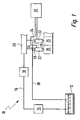
- a fuel system as a whole bears the reference numeral 10. It comprises a fuel tank 12, from which an electric fuel pump 14 delivers fuel into a low-pressure fuel line 16. This leads to a high pressure fuel pump 18.
- the high pressure fuel pump 18 is a piston pump which is driven by a camshaft (not shown) of an internal combustion engine (also not shown) to which the fuel system 10 belongs.
- the high pressure fuel pump 18 compresses the fuel to a very high pressure and delivers it to a fuel rail 20. This is also referred to as a "rail". In it the fuel is stored under high pressure.
- a plurality of fuel injectors 22 are connected to the fuel manifold 20 .
- these have high-pressure connections 24.
- the fuel injectors 22 inject the fuel directly into their associated combustion chambers 26 of the internal combustion engine.
- the fuel injectors 22 also each have a low pressure port 28, from which a return line 30 leads back to the fuel tank 12.
- the operation of the internal combustion engine, the fuel system 10 and in particular the fuel injectors 22 is controlled by a control and regulating device 32. For this purpose, this is connected via lines (without reference numeral) with the fuel injectors 22.
- the fuel system shown in Figure 1 can be used equally in gasoline and diesel internal combustion engines.
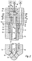
- the fuel injectors 22 include a housing that includes a nozzle body 34, an intermediate piece 36, and an upper end piece 38.
- a recess 40 is present, in which two coaxially arranged valve elements 42 and 44 are present.
- the outer tubular valve element 42 cooperates with a valve seat 46 which is present in the lower region of the recess 40 in FIG. He also outlet openings 48 are assigned.
- the inner valve member 44 cooperates with a valve seat 50 and is associated with fuel exit apertures 52.
- the outer valve element 42 is guided in the recess 40.
- the inner valve element 44 is guided in the outer valve element 42.
- the outer circumferential surface of the outer valve element 42 has a shoulder 54 in the region of the upper end of the outer valve element 42 in FIG.
- a support ring 56 At this is a support ring 56.
- On the support ring 56 supports one end of a compression spring 58 from whose other end a first sealing sleeve 60 acts against the intermediate piece 36.
- the first sealing sleeve 60 is pushed fluid-tight onto the upper end of the outer valve element 42 in FIG.
- the first sealing sleeve 60 and the outer valve element 42 are movable relative to each other at least in the axial direction.
- the first sealing sleeve 60 has at its upper edge in FIG. 2 a tapered circumferential sealing edge 62. In the region of this tapered sealing edge 62, a radially extending channel 64 is worked through the sealing sleeve at a location of the first sealing sleeve 60.
- the upper edge of the outer valve element 42 in FIG. 2 forms a flat annular surface, which represents an annular pressure surface 66. Their importance will be explained in detail below.
- the intermediate piece 36 is an annular and the nozzle body 34 open towards recess 68 is present.
- a compression spring 70 is supported, the other end of which acts on an edge of a second annular sealing sleeve 72.
- the second sealing sleeve 72 is slidably guided in the annular recess 68 and fluid-tight.
- Their lower edge in FIG. 2 is tapered in a manner similar to the edge 62 of the first sealing sleeve 60 and forms a sealing edge 74. This rests against an upper end surface of the inner valve element 44.
- This upper end surface forms a pressure surface 76, which will be explained in greater detail below.
- the diameter of the sealing edge 74 of the second sealing sleeve 72 is slightly smaller than the outer diameter of the inner valve element 44.
- the compression spring 58, the first sealing sleeve 60, the compression spring 70, the second sealing sleeve 72 and the two valve elements 42 and 44 are arranged coaxially with each other.
- an outer annular control chamber 78 is present. Between the circular pressure surface 76 of the inner valve element 44, the second sealing sleeve 72 and the intermediate piece 36, an inner control chamber 80 is formed.
- a 3/3-way valve 82 is present in the upper end 38 of the fuel injection device 22 in the upper end 38 of the fuel injection device 22, a 3/3-way valve 82 is present. Whose valve element 84 is actuated by a piezoelectric actuator 88 via a plunger 86.
- the valve member 84 is disposed in a control chamber 90 and cooperates with a valve seat 92 shown in FIGS. 2 and 3 and a valve seat 94 lower in FIGS. 2 and 3. From the 3/3-way valve 82 performs a central channel 96 via an outflow throttle 98 to the inner control chamber 80. Further, from the 3/3-way valve 82, an off-center channel 100 also via an outflow throttle 102 to the outer annular control chamber 78th
- a channel 104 leads from the 3/3-way valve 82 to the low pressure port 28. This is also connected via a leakage channel 106 with the annular recess 68 in the intermediate piece 36. From the high-pressure port 24, a channel 108 leads in the upper end 38 and the intermediate piece 36 to the recess 40 in the nozzle body 34. Another channel 110 leads from the high-pressure port 24 obliquely via an inflow throttle 112 to the central channel 96. From the recess 40 leads to the longitudinal axis of the recess 40 parallel channel 114 to one in the lower part of the Recess 40 existing annular space 116th
- the fuel injector 22 shown in Figs. 2 and 3 operates as follows:
- the piezoactuator 88 is actuated by the control and regulating device 32 in such a way that the valve element 84 of the 3/3-way valve 82 comes into contact with the lower valve seat 94.
- the fluid connection between the control chamber 80 of the inner valve member 44 and the low pressure port 28 is still interrupted, via the outflow throttle 102, the flow channel 100, the control chamber 90 and the channel 104 can now but fuel from the annular control chamber 78 of the outer valve element 42 to the low pressure connection 28 out flow.
- the piezoelectric actuator 88 is controlled by the control and regulating device 32 in such a way that the valve element 84 is in an intermediate switching position, that is to say neither in contact at the upper valve seat 92 is still in abutment with the lower valve seat 94.
- both control chambers 78 and 80 are connected to the low pressure port 28.
- the amount of force resultant which acts on the pressure surface 76 of the inner valve element 44 thus decreases, and the inner valve element 44 can lift off the valve seat 50 due to the high pressure acting radially outward from the valve seat 50 at its conical tip.
- control chambers 78 and 80 are arranged coaxially with each other and approximately at the same axial height.
- the sealing of the control chambers 78 and 80 takes place essentially through the sealing sleeves 60 and 72.
Landscapes
- Engineering & Computer Science (AREA)
- Chemical & Material Sciences (AREA)
- Combustion & Propulsion (AREA)
- Mechanical Engineering (AREA)
- General Engineering & Computer Science (AREA)
- Physics & Mathematics (AREA)
- Fluid Mechanics (AREA)
- Fuel-Injection Apparatus (AREA)
Abstract
Claims (8)
- Dispositif d'injection de carburant (22) pour un moteur à combustion interne, comprenant un boîtier (34, 36, 38), un évidement (40) prévu dans le boîtier (34, 36, 38), au moins deux éléments de soupape (42, 44) disposés coaxialement l'un par rapport à l'autre dans l'évidement (40) et qui coopèrent respectivement avec un siège de soupape (46, 50) correspondant, et auxquels est respectivement associée au moins une ouverture de sortie de carburant (48, 52), avec au moins une chambre de commande (80) délimitée par une surface de pression (76) associée à un élément de soupape (44) et dont la résultante de force est dirigée pendant le fonctionnement vers le siège de soupape (50) de l'élément de soupape (44), au moins deux chambres de commande (78, 80) étant respectivement associées à un élément de soupape (42, 44) avec une surface de pression (66, 76) dont la résultante de force est dirigée pendant le fonctionnement vers le siège de soupape (46, 50) de l'élément de soupape (42, 44), les chambres de commande (78, 80) étant coaxiales et sensiblement à la même hauteur axiale,
caractérisé en ce que
les chambres de commande (78, 80) sont séparées l'une de l'autre par un élément de séparation (72) en forme de douille. - Dispositif d'injection de carburant (22) selon la revendication 1,
caractérisé en ce que
l'élément de séparation en forme de douille est une pièce (72) distincte sollicitée par un dispositif de serrage (70) muni d'une arête d'étanchéité (74) contre la surface de pression (76) d'un des éléments de soupape (44). - Dispositif d'injection de carburant (22) selon l'une quelconque des revendications 1 ou 2,
caractérisé en ce que
les chambres de commande (78, 80) sont respectivement délimitées vers l'extérieur par un élément de séparation en forme de douille (60, 72) sollicité par un dispositif de serrage (70, 58). - Dispositif d'injection de carburant (22) selon l'une quelconque des revendications précédentes,
caractérisé en ce qu'
au moins un élément de soupape (42, 44) est sollicité contre son siège de soupape (46, 50) par un dispositif de serrage (58, 70) appuyé contre un élément de séparation (60, 72). - Dispositif d'injection de carburant (22) selon la revendication 4,
caractérisé en ce que
le dispositif de serrage (58), qui sollicite l'élément de séparation (60) en forme de douille, délimitant vers l'extérieur la chambre de commande (78) de l'élément de soupape (42) radialement extérieur, prend appui sur une bague d'appui (56) appliquée sur l'élément de soupape (42) radialement extérieur. - Dispositif d'injection de carburant (22) selon l'une quelconque des revendications 3 à 5,
caractérisé en ce que
la chambre de commande (78) de l'élément de soupape (42) radialement extérieur est reliée à un raccord haute pression (24) par un canal (64) dans l'élément de séparation (60) en forme de douille qui la délimite vers l'extérieur. - Dispositif d'injection de carburant (22) selon l'une quelconque des revendications précédentes,
caractérisé en ce qu'
il comprend une soupape à 3/3 voies (82) reliée à un raccord basse pression (28) et aux deux chambres de commande (78, 80). - Dispositif d'injection de carburant (22) selon la revendication 7,
caractérisé en ce que
dans une première position de commutation de la soupape à 3/3 voies (82) les deux éléments de soupape (42, 44) s'appliquent contre leurs sièges de soupape (46, 50), dans une deuxième position de commutation l'élément de soupape (42) radialement extérieur est soulevé de son siège de soupape (46), et l'élément de soupape (44) radialement intérieur s'applique contre son siège de soupape (50), et dans une troisième position de commutation les deux éléments de soupape (42, 44) sont soulevés de leurs sièges de soupape (46, 50).
Applications Claiming Priority (3)
| Application Number | Priority Date | Filing Date | Title |
|---|---|---|---|
| DE10246974 | 2002-10-09 | ||
| DE2002146974 DE10246974A1 (de) | 2002-10-09 | 2002-10-09 | Kraftstoffeinspritzvorrichtung für eine Brennkraftmaschine |
| PCT/DE2003/001676 WO2004033890A1 (fr) | 2002-10-09 | 2003-05-23 | Dispositif d'injection de carburant destine a un moteur a combustion interne |
Publications (2)
| Publication Number | Publication Date |
|---|---|
| EP1552135A1 EP1552135A1 (fr) | 2005-07-13 |
| EP1552135B1 true EP1552135B1 (fr) | 2006-06-14 |
Family
ID=32038355
Family Applications (1)
| Application Number | Title | Priority Date | Filing Date |
|---|---|---|---|
| EP03740026A Expired - Lifetime EP1552135B1 (fr) | 2002-10-09 | 2003-05-23 | Dispositif d'injection de carburant destine a un moteur a combustion interne |
Country Status (3)
| Country | Link |
|---|---|
| EP (1) | EP1552135B1 (fr) |
| DE (2) | DE10246974A1 (fr) |
| WO (1) | WO2004033890A1 (fr) |
Families Citing this family (20)
| Publication number | Priority date | Publication date | Assignee | Title |
|---|---|---|---|---|
| DE10326043A1 (de) * | 2003-06-10 | 2004-12-30 | Robert Bosch Gmbh | Einspritzdüse für Brennkraftmaschinen |
| DE10334209A1 (de) * | 2003-07-26 | 2005-02-10 | Robert Bosch Gmbh | Kraftstoff-Einspritzvorrichtung für eine Brennkraftmaschine |
| DE10343998A1 (de) * | 2003-09-23 | 2005-04-14 | Robert Bosch Gmbh | Einspritzdüse |
| WO2005119045A1 (fr) * | 2004-06-03 | 2005-12-15 | Siemens Aktiengesellschaft | Soupape d'injection |
| DE102004030445A1 (de) * | 2004-06-24 | 2006-01-12 | Robert Bosch Gmbh | Kraftstoffeinspritzvorrichtung |
| DE102004032700B3 (de) * | 2004-07-06 | 2005-10-06 | Siemens Ag | Kraftstoffinjektor mit einem Kugelsitz für ein zweistufiges Servoventil |
| DE102004036367B3 (de) * | 2004-07-27 | 2005-10-13 | Siemens Ag | Einspritzventil |
| DE102004041172B3 (de) * | 2004-08-25 | 2006-01-05 | Siemens Ag | Einspritzventil |
| DE102004051406B4 (de) * | 2004-10-21 | 2008-03-20 | Siemens Ag | Kraftstoffinjektor mit einer im Düsenkörper geführten Hohlnadel einer Registerdüse |
| DE102004051756A1 (de) * | 2004-10-23 | 2006-04-27 | Robert Bosch Gmbh | Kraftstoffeinspritzventil für Brennkraftmaschinen |
| DE102004060550A1 (de) * | 2004-12-16 | 2006-07-06 | Robert Bosch Gmbh | Kraftstoffeinspritzdüse |
| DE102005001284A1 (de) * | 2005-01-11 | 2006-07-20 | Siemens Ag | Kraftstoffinjektor mit einer Registerdüse, deren innere Düsennadel in einem Nadelführungskörper geführt wird |
| DE102005016796A1 (de) * | 2005-04-12 | 2006-10-19 | Robert Bosch Gmbh | Zweistufig öffnender Kraftstoffinjektor |
| DE102005023368B4 (de) * | 2005-05-20 | 2008-09-11 | Continental Automotive Gmbh | Düsenbaugruppe für ein Einspritzventil und Einspritzventil |
| DE102005042786B4 (de) * | 2005-09-08 | 2009-04-16 | Siemens Ag | Kraftstoffinjektor mit hermetisch abgedichtetem Hydrauliksystem |
| DE102005046669A1 (de) * | 2005-09-29 | 2007-04-05 | Robert Bosch Gmbh | Lochdüse für eine Kraftstoff-Einspritzvorrichtung eines Kraftstoff-Einspritzsystem |
| WO2008017614A1 (fr) | 2006-08-09 | 2008-02-14 | Siemens Aktiengesellschaft | Dispositif d'injection de combustible pour un moteur à combustion |
| DE102007011685A1 (de) | 2007-03-09 | 2008-09-11 | Robert Bosch Gmbh | Kraftstoffinjektor mit verbessertem Steuerventil |
| JP4772016B2 (ja) * | 2007-09-07 | 2011-09-14 | トヨタ自動車株式会社 | 内燃機関の燃料噴射制御装置 |
| DE102014211287A1 (de) | 2014-06-12 | 2015-12-17 | Engineering Center Steyr Gmbh & Co. Kg | Fluid-Einspritzvorrichtung für eine Verbrennungskraftmaschine |
Family Cites Families (4)
| Publication number | Priority date | Publication date | Assignee | Title |
|---|---|---|---|---|
| GB9709678D0 (en) * | 1997-05-14 | 1997-07-02 | Lucas Ind Plc | Fuel injector |
| GB0021296D0 (en) * | 2000-08-30 | 2000-10-18 | Ricardo Consulting Eng | A dual mode fuel injector |
| DE10122241A1 (de) * | 2001-05-08 | 2002-12-05 | Bosch Gmbh Robert | Kraftstoffeinspritzventil für Brennkraftmaschinen |
| US6637675B2 (en) * | 2001-07-13 | 2003-10-28 | Cummins Inc. | Rate shaping fuel injector with limited throttling |
-
2002
- 2002-10-09 DE DE2002146974 patent/DE10246974A1/de not_active Withdrawn
-
2003
- 2003-05-23 DE DE50303869T patent/DE50303869D1/de not_active Expired - Lifetime
- 2003-05-23 WO PCT/DE2003/001676 patent/WO2004033890A1/fr not_active Application Discontinuation
- 2003-05-23 EP EP03740026A patent/EP1552135B1/fr not_active Expired - Lifetime
Also Published As
| Publication number | Publication date |
|---|---|
| EP1552135A1 (fr) | 2005-07-13 |
| DE10246974A1 (de) | 2004-04-22 |
| DE50303869D1 (de) | 2006-07-27 |
| WO2004033890A1 (fr) | 2004-04-22 |
Similar Documents
| Publication | Publication Date | Title |
|---|---|---|
| EP1552135B1 (fr) | Dispositif d'injection de carburant destine a un moteur a combustion interne | |
| WO2003069151A1 (fr) | Soupape d'injection de carburant pour moteurs a combustion interne | |
| EP1395744B1 (fr) | Appareil d'injection de carburant pour moteurs a combustion, en particulier injecteur de type common rail, systeme d'alimentation en carburant et moteur a combustion | |
| EP1990532A1 (fr) | Injecteur de carburant pour un moteur à combustion interne comprenant un système d'injection à rampe commune | |
| EP1952011B1 (fr) | Dispositif d'injection de carburant pour moteur a combustion interne a injection directe de carburant | |
| EP1552136B1 (fr) | Dispositif d'injection de carburant destine a un moteur a combustion interne | |
| DE10058130A1 (de) | Kraftstoffeinspritzsystem für Brennkraftmaschinen | |
| DE10353045A1 (de) | Kraftstoffeinspritzventil | |
| EP1413742B1 (fr) | Dispositif d'injection de combustible pour un moteur à combustion interne | |
| DE10031580A1 (de) | Druckgesteuertes Steuerteil für Common-Rail-Injektoren | |
| EP1682769A1 (fr) | Injecteur de carburant dote d'un element de soupape d'injection en plusieurs parties, en commande directe | |
| DE102007010498A1 (de) | Injektor zum Einspritzen von Kraftstoff in einen Brennraum einer Brennkraftmaschine | |
| EP1526274B1 (fr) | Dispositif d'injection de carburant, en particulier pour un moteur à combustion interne à injection directe | |
| DE10357769B4 (de) | Kraftstoffeinspritzventil | |
| WO2003031803A1 (fr) | Dispositif d'injection de carburant, en particulier injecteur pour moteurs a combustion interne a injection directe, et systeme de carburant et moteur a combustion interne y relatifs | |
| DE10160490B4 (de) | Kraftstoff-Einspritzvorrichtung, Kraftstoffsystem sowie Brennkraftmaschine | |
| DE10305509A1 (de) | Kraftstoffeinspritzventil für eine Brennkraftmaschine | |
| WO2006079425A1 (fr) | Système d'injection de carburant | |
| WO2001014721A1 (fr) | Dispositif d'injection de carburant pour moteurs a combustion interne | |
| DE10158588C1 (de) | Kraftstoff-Einspritzvorrichtung, Kraftstoffsystem sowie Brennkraftmaschine | |
| WO2005014998A1 (fr) | Dispositif d'injection de carburant notamment destine a un moteur a combustion interne a injection de carburant directe | |
| DE10305508A1 (de) | Kraftstoffeinspritzventil für eine Brennkraftmaschine sowie Verfahren zum Betreiben einer Brennkraftmaschine | |
| WO2004063553A1 (fr) | Dispositif d'injection de carburant | |
| EP2085604A1 (fr) | Injecteur de carburant | |
| WO2005014996A1 (fr) | Dispositif d'injection de carburant pour moteur a combustion interne |
Legal Events
| Date | Code | Title | Description |
|---|---|---|---|
| PUAI | Public reference made under article 153(3) epc to a published international application that has entered the european phase |
Free format text: ORIGINAL CODE: 0009012 |
|
| 17P | Request for examination filed |
Effective date: 20050509 |
|
| AK | Designated contracting states |
Kind code of ref document: A1 Designated state(s): AT BE BG CH CY CZ DE DK EE ES FI FR GB GR HU IE IT LI LU MC NL PT RO SE SI SK TR |
|
| GRAP | Despatch of communication of intention to grant a patent |
Free format text: ORIGINAL CODE: EPIDOSNIGR1 |
|
| RAX | Requested extension states of the european patent have changed |
Extension state: MK Extension state: LV Extension state: LT Extension state: AL |
|
| DAX | Request for extension of the european patent (deleted) | ||
| RBV | Designated contracting states (corrected) |
Designated state(s): DE FR IT |
|
| GRAS | Grant fee paid |
Free format text: ORIGINAL CODE: EPIDOSNIGR3 |
|
| GRAA | (expected) grant |
Free format text: ORIGINAL CODE: 0009210 |
|
| AK | Designated contracting states |
Kind code of ref document: B1 Designated state(s): DE FR IT |
|
| PG25 | Lapsed in a contracting state [announced via postgrant information from national office to epo] |
Ref country code: IT Free format text: LAPSE BECAUSE OF FAILURE TO SUBMIT A TRANSLATION OF THE DESCRIPTION OR TO PAY THE FEE WITHIN THE PRESCRIBED TIME-LIMIT;WARNING: LAPSES OF ITALIAN PATENTS WITH EFFECTIVE DATE BEFORE 2007 MAY HAVE OCCURRED AT ANY TIME BEFORE 2007. THE CORRECT EFFECTIVE DATE MAY BE DIFFERENT FROM THE ONE RECORDED. Effective date: 20060614 |
|
| REF | Corresponds to: |
Ref document number: 50303869 Country of ref document: DE Date of ref document: 20060727 Kind code of ref document: P |
|
| ET | Fr: translation filed | ||
| PLBE | No opposition filed within time limit |
Free format text: ORIGINAL CODE: 0009261 |
|
| STAA | Information on the status of an ep patent application or granted ep patent |
Free format text: STATUS: NO OPPOSITION FILED WITHIN TIME LIMIT |
|
| 26N | No opposition filed |
Effective date: 20070315 |
|
| PGFP | Annual fee paid to national office [announced via postgrant information from national office to epo] |
Ref country code: FR Payment date: 20090519 Year of fee payment: 7 Ref country code: IT Payment date: 20090525 Year of fee payment: 7 |
|
| REG | Reference to a national code |
Ref country code: FR Ref legal event code: ST Effective date: 20110131 |
|
| PG25 | Lapsed in a contracting state [announced via postgrant information from national office to epo] |
Ref country code: IT Free format text: LAPSE BECAUSE OF NON-PAYMENT OF DUE FEES Effective date: 20100523 |
|
| PG25 | Lapsed in a contracting state [announced via postgrant information from national office to epo] |
Ref country code: FR Free format text: LAPSE BECAUSE OF NON-PAYMENT OF DUE FEES Effective date: 20100531 |
|
| PGFP | Annual fee paid to national office [announced via postgrant information from national office to epo] |
Ref country code: DE Payment date: 20120723 Year of fee payment: 10 |
|
| PG25 | Lapsed in a contracting state [announced via postgrant information from national office to epo] |
Ref country code: DE Free format text: LAPSE BECAUSE OF NON-PAYMENT OF DUE FEES Effective date: 20131203 |
|
| REG | Reference to a national code |
Ref country code: DE Ref legal event code: R119 Ref document number: 50303869 Country of ref document: DE Effective date: 20131203 |