EP2085604A1 - Injecteur de carburant - Google Patents
Injecteur de carburant Download PDFInfo
- Publication number
- EP2085604A1 EP2085604A1 EP09100054A EP09100054A EP2085604A1 EP 2085604 A1 EP2085604 A1 EP 2085604A1 EP 09100054 A EP09100054 A EP 09100054A EP 09100054 A EP09100054 A EP 09100054A EP 2085604 A1 EP2085604 A1 EP 2085604A1
- Authority
- EP
- European Patent Office
- Prior art keywords
- valve element
- injection valve
- throttle channel
- injector
- chamber
- Prior art date
- Legal status (The legal status is an assumption and is not a legal conclusion. Google has not performed a legal analysis and makes no representation as to the accuracy of the status listed.)
- Withdrawn
Links
Images
Classifications
-
- F—MECHANICAL ENGINEERING; LIGHTING; HEATING; WEAPONS; BLASTING
- F02—COMBUSTION ENGINES; HOT-GAS OR COMBUSTION-PRODUCT ENGINE PLANTS
- F02M—SUPPLYING COMBUSTION ENGINES IN GENERAL WITH COMBUSTIBLE MIXTURES OR CONSTITUENTS THEREOF
- F02M47/00—Fuel-injection apparatus operated cyclically with fuel-injection valves actuated by fluid pressure
- F02M47/02—Fuel-injection apparatus operated cyclically with fuel-injection valves actuated by fluid pressure of accumulator-injector type, i.e. having fuel pressure of accumulator tending to open, and fuel pressure in other chamber tending to close, injection valves and having means for periodically releasing that closing pressure
- F02M47/027—Electrically actuated valves draining the chamber to release the closing pressure
-
- F—MECHANICAL ENGINEERING; LIGHTING; HEATING; WEAPONS; BLASTING
- F02—COMBUSTION ENGINES; HOT-GAS OR COMBUSTION-PRODUCT ENGINE PLANTS
- F02M—SUPPLYING COMBUSTION ENGINES IN GENERAL WITH COMBUSTIBLE MIXTURES OR CONSTITUENTS THEREOF
- F02M61/00—Fuel-injectors not provided for in groups F02M39/00 - F02M57/00 or F02M67/00
- F02M61/04—Fuel-injectors not provided for in groups F02M39/00 - F02M57/00 or F02M67/00 having valves, e.g. having a plurality of valves in series
- F02M61/10—Other injectors with elongated valve bodies, i.e. of needle-valve type
- F02M61/12—Other injectors with elongated valve bodies, i.e. of needle-valve type characterised by the provision of guiding or centring means for valve bodies
-
- F—MECHANICAL ENGINEERING; LIGHTING; HEATING; WEAPONS; BLASTING
- F02—COMBUSTION ENGINES; HOT-GAS OR COMBUSTION-PRODUCT ENGINE PLANTS
- F02M—SUPPLYING COMBUSTION ENGINES IN GENERAL WITH COMBUSTIBLE MIXTURES OR CONSTITUENTS THEREOF
- F02M2547/00—Special features for fuel-injection valves actuated by fluid pressure
- F02M2547/001—Control chambers formed by movable sleeves
-
- F—MECHANICAL ENGINEERING; LIGHTING; HEATING; WEAPONS; BLASTING
- F02—COMBUSTION ENGINES; HOT-GAS OR COMBUSTION-PRODUCT ENGINE PLANTS
- F02M—SUPPLYING COMBUSTION ENGINES IN GENERAL WITH COMBUSTIBLE MIXTURES OR CONSTITUENTS THEREOF
- F02M2547/00—Special features for fuel-injection valves actuated by fluid pressure
- F02M2547/008—Means for influencing the flow rate out of or into a control chamber, e.g. depending on the position of the needle
-
- F—MECHANICAL ENGINEERING; LIGHTING; HEATING; WEAPONS; BLASTING
- F02—COMBUSTION ENGINES; HOT-GAS OR COMBUSTION-PRODUCT ENGINE PLANTS
- F02M—SUPPLYING COMBUSTION ENGINES IN GENERAL WITH COMBUSTIBLE MIXTURES OR CONSTITUENTS THEREOF
- F02M63/00—Other fuel-injection apparatus having pertinent characteristics not provided for in groups F02M39/00 - F02M57/00 or F02M67/00; Details, component parts, or accessories of fuel-injection apparatus, not provided for in, or of interest apart from, the apparatus of groups F02M39/00 - F02M61/00 or F02M67/00; Combination of fuel pump with other devices, e.g. lubricating oil pump
- F02M63/02—Fuel-injection apparatus having several injectors fed by a common pumping element, or having several pumping elements feeding a common injector; Fuel-injection apparatus having provisions for cutting-out pumps, pumping elements, or injectors; Fuel-injection apparatus having provisions for variably interconnecting pumping elements and injectors alternatively
- F02M63/0225—Fuel-injection apparatus having a common rail feeding several injectors ; Means for varying pressure in common rails; Pumps feeding common rails
Definitions
- the invention relates to an injector, in particular a common rail injector, for injecting fuel in a combustion chamber of an internal combustion engine according to the preamble of claim 1.
- Known injectors include a control valve (servo valve) by means of which the fuel pressure can be influenced within a limited by an injection valve element control chamber.
- a control valve servo valve
- the control chamber is connected to a low-pressure region of the injector via an outlet throttle channel, with the result that the fuel pressure inside the control chamber and thus the closing force acting on the injection valve element drop, whereby the injection valve element is seated from its injection valve element seat lifts and fuel can flow through a nozzle hole arrangement in a combustion chamber of an internal combustion engine.
- the two-part injection valve element on its axially limiting the control chamber end face has a central stop with a flat end face which closes an outlet throttle when the injection valve element is open.
- a guide for the injection valve element and the outlet throttle channel in a common Valve piece formed.
- a disadvantage is the lack of sealing of the outlet throttle channel and a possibly occurring hydraulic sticking of the injection valve element on the valve piece.
- an injector which has an end member provided with a throttle channel at its end face on its injection valve element. Even if the end member rests in the edge region of the mouth of the outlet throttle channel, the control chamber via the throttle channel is still hydraulically connected to the outlet throttle channel.
- the invention has for its object to provide an injector, in which a good seal of the discharge throttle channel can be ensured with an open injection valve element without it being absolutely necessary to center the injection valve element relative to the orifice of a discharge throttle exactly.
- the invention has recognized that in order to minimize the control quantity flowing out of the control chamber in the direction of the injector return, it is advantageous to seal the outlet throttle channel by means of the injection valve element when it is in its open position. So that a good seal of the outlet throttle channel is ensured by the one- or multi-part injection valve element, without having to take care that the guide for the injection valve element and the mouth opening of the outlet throttle channel are aligned exactly, the invention proposes, at the end face of the injection valve element a circumferential, preferably circular, sealing edge (usually biting edge) to provide, which seals the outlet throttle channel in the open position of the injection valve element relative to the (remaining) control chamber.
- one after the Concept of the invention formed injector on the front side of the injection valve element designed as a sealing edge stroke stop provided, which rests with the injection valve element in its open position on a discharge throttle channel receiving component.
- the diameter of the sealing edge is preferably selected to be at most as large as is absolutely necessary in order to securely seal the outlet throttle channel.
- the diameter of the sealing edge should be selected so that when the control valve (servo valve) is open, a sufficiently large excess of force is established on the injection valve element so that it remains open.
- the diameter of the sealing edge is selected so that when the control valve is open, the opening force acting on the injection valve element is greater than the closing force acting on the injection valve element.
- the outlet throttle channel is arranged in a throttle plate axially delimiting the control chamber, wherein the closed sealing edge provided on the end side of the injection valve element surrounds a mouth opening of the outlet throttle channel in the throttle plate radially on the outside.
- the injection valve element in its open position, is supported on the preferably flat (lower, ie the combustion chamber facing) surface of the throttle plate with a radial distance from the outlet opening of the outlet throttle channel.
- a seal of the outlet throttle channel with respect to the control chamber is also achieved when the injection valve element is not aligned exactly with the mouth opening. It is only essential that the mouth opening of the outlet throttle channel is located completely in a region radially within the sealing edge.
- the mouth opening of the outlet throttle channel is, at least approximately, centric with respect to the (extended) longitudinal central axis of the injection valve element, in particular in order to realize a symmetrical component load, is advantageous.
- an embodiment of the injector is possible in which, despite ensuring a seal of the outlet throttle when the injection valve element is open, the control chamber is not bounded radially on the outside by the same component in which the outlet throttle channel is accommodated, but instead by a sleeve which is in axial direction is spring-loaded by means of a spring on the throttle plate.
- the manufacture of the throttle plate is thereby simplified.
- the sleeve is surrounded by under high pressure fuel to minimize the guide gap between the sleeve and the injection valve element.
- the throttle plate is particularly preferably a simple cylinder plate with two parallel end faces, wherein the control chamber adjoins a first (lower) end face and a valve chamber of the control valve at the other (upper) end face.
- the control chamber is supplied with advantage via an inlet throttle channel permanently under high pressure (rail pressure) stagnant fuel.
- the inlet throttle channel is located in the throttle plate.
- the inlet throttle channel is connected via a front-side hydraulic bag with a supply channel in the injector via which a high-pressure chamber of the injector with fuel from a high-pressure fuel storage (rail) is supplied.
- the inlet throttle is introduced into the sleeve, preferably as a radial channel.
- an embodiment of the injector is preferred in which the diameter ratio between the minimum diameter of the outlet throttle channel and the minimum diameter of the inlet throttle channel is selected from a range between about 0.8 and about 0.9. Particularly preferred is an embodiment in which this ratio is about 0.86.
- the end face of the injection valve element is formed radially within the sealing edge of at least two, preferably only two, mutually angularly arranged annular surface portions, wherein preferably immediately adjacent to the sealing edge annular surface portion less strongly relative to a perpendicular from the Intersected with the longitudinal center axis of the injection valve element interspersed plane, as a radially inwardly adjacent to this annular surface portion annular surface portion.
- a valve chamber of the control valve which is hydraulically connected via the outlet throttle with the control chamber, via a connecting channel (bypass) with a high-pressure region of the injector, in particular with a control chamber radially inwardly receiving pressure chamber, connected so that when the control valve is closed, fuel can flow into the valve chamber via the connecting channel and into the control chamber via the outlet throttle channel.
- the control chamber is not only pressurized only via the inlet throttle channel, but also backwards over the outlet throttle channel with high pressure until the force equilibrium is reached at the injection valve element. In this way, an accelerated closing of the injection valve element can be realized.
- control valve is designed as a 3/2-way valve and the connecting channel in a switching position in which the control chamber is hydraulically connected to the low pressure region of the injector, lides preferably with the end face of an axially adjustable bisti ,
- the actuator for actuating the control valve is designed as a piezo actuator.
- This preferably comprises a multiplicity of stacked crystal platelets which expand when energized.
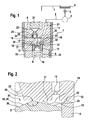
- Fig. 1 is a fragmentary designed as a common rail injector injector 1 for injecting fuel into a combustion chamber of an internal combustion engine (not shown) shown.
- the injector 1 is supplied via a high-pressure supply line 2 from a high-pressure fuel accumulator 3 (rail) with high pressure, in the embodiment shown above 2000 bar, standing fuel, especially diesel.
- the fuel high-pressure accumulator 3 is supplied with fuel from a low-pressure reservoir 5 by a high-pressure pump 4 designed in particular as a radial piston pump.
- a low-pressure region 6 of the injector 1 is hydraulically connected via a return line 7 to the reservoir 5. In the return line 7, a later to be explained control amount of fuel is discharged and fed via the high pressure pump 4 to the high-pressure circuit again.
- the injector 1 comprises a nozzle body 8, in which an injection valve element 9 (here nozzle needle) is adjustable in the axial direction between an open position and a closed position. In its open position, the injection valve element 9 releases the fuel flow from a nozzle hole arrangement (not shown) into the combustion chamber of the internal combustion engine.
- an injection valve element 9 here nozzle needle
- the nozzle body 8 passes through in the axial direction a nozzle retaining nut 10, which is screwed to an injector 11.
- an injector 11 By means of the nozzle retaining nut 10, the nozzle body 8 and the injector 11 are clamped against a throttle plate 12.
- the control chamber 14 Radially outwardly, the control chamber 14 is bounded by a sleeve 15, which is supported by a compression spring 16, which is also a closing spring for the injection valve element 9 and which is supported on a circumferential collar of the injection valve element 9, not shown, in the axial direction to a lower plane in the drawing, level throttle plate end 17 pressed.
- the lower, not shown, the combustion chamber facing, throttle plate end 17 extends parallel to an upper throttle plate end face 18.
- the control chamber 14 In the axial upward direction, the control chamber 14 is bounded by the lower throttle plate end side 17th
- control chamber 14 opens a fed into the throttle plate 12 inlet throttle channel 19 which is connected on the upper throttle plate face 18 via a hydraulic bag 20 with a radially adjacent supply channel 21, which in turn is hydraulically connected to the high-pressure supply line 2.
- the supply channel 21 passes through the throttle plate 12 in the axial direction and opens into a pressure chamber 22 which surrounds the control chamber 14 limiting sleeve 15 radially outward.
- the control chamber 14 is supplied with fuel under high pressure.
- the control chamber 14 is connected to an axially extending outlet throttle channel 23 with a valve chamber 24 of a control valve 25 (servo valve).
- the valve chamber 24 is located on the upper throttle plate end face 18.
- a control valve member 26 is adjustable in the axial direction between an upper and a lower switching position.
- a piezaktaktor 27 shown only partially is provided. When energized, the piezoelectric actuator 27 expands and the control valve member 26 is on the upper throttle plate face 18 against the force of a control closing spring 28 which is disposed within the valve chamber 24, adjusted.
- a connecting channel 29, which opens out of the pressure chamber 22, closed by the (lower) end face of the control valve element 26.
- the piezoelectric actuator 27 is energized, whereby the control valve element 26 is adjusted in the drawing plane down to the throttle plate 12 and thereby closes the connecting channel 29.
- the control chamber 14 is hydraulically connected to the low-pressure region 6 and thus to the reservoir 5.
- the flow cross-sections of the outlet throttle channel 23 and the inlet throttle channel 19 are matched to one another in such a way that a net outflow of fuel (control quantity) from the control chamber 14 via the outlet throttle channel 23 and the valve chamber 24 into the low-pressure region 6 results.
- the fuel pressure within the control chamber 14 decreases rapidly, whereby the injection valve element 9 is moved upward in the plane of the drawing.
- the adjusting movement is limited by the throttle plate 12, at which the injection valve element 9 in its open position with a circular, end-side sealing edge 30 (biting edge) is supported.
- the sealing edge 30 encloses in the in Fig. 1 Not shown opening position of the injection valve element 9, a mouth opening 31 of the outlet throttle channel 23 radially outward and seals the outlet throttle channel 23 from the control chamber 14, so that a further control flow rate is prevented.
- the energization of the piezoelectric actuator 27 is interrupted, whereby the control valve element 26 is adjusted due to the spring force of the control closing spring 28 in its upper switching position, whereby the low pressure region 6 of the injector 1 is hydraulically separated from the valve chamber 24.
- control valve element 26 fuel 29 flows from the pressure chamber 22 via the connecting channel 29 into the valve chamber 24 and from there backwards via the outlet throttle channel 23 into the control chamber.
- the injection valve element 9, supported by the spring force of the compression spring 16 (closing spring), is moved to its injector seat, not shown, and blocks there the nozzle hole arrangement, not shown.
- FIG. 2 an enlarged view of a possible embodiment of the (upper) end face of an injection valve element 9 of an injector 1 is shown.
- the injection valve element 9 with its upper in the drawing plane, the throttle plate 12 facing end face 13th
- the injection valve element 9 in its closed position and is supported by means of a circumferentially closed sealing edge 30 on the lower throttle plate face 17 from and in a region radially outside a central mouth opening 31 in the embodiment according to Fig. 2
- the sleeve 15 is supported on the throttle plate 12 via a sleeve bite edge 32.
- the inlet throttle channel 19 opens into a region of the control chamber 14 radially between the (outer) sleeve biting edge 32 and the (inner) sealing edge 30 on the end face 13 of the injection valve element 9.
- An inner sealing edge angle ⁇ is spanned between a radially outer annular surface 33 of the end face 13 and a Ring surface portion 34 which is located radially within the sealing edge 30 and immediately adjacent thereto.
- An inclination angle of the annular surface portion 34 not provided with a reference numeral is smaller than an inclination angle of an annular inner annular surface portion 35 radially inwardly adjacent to a circular planar central surface 36 parallel to the lower throttle plate end surface 17.
- the application of the invention is also possible with injectors with pressure-balanced or partially pressure-balanced control valves.
- no switchable connection channel 45 is present.
- the control valve has a first valve chamber and a second valve chamber.
- the first valve chamber is constantly connected to the low-pressure region and the second valve chamber via an additional Golfdrosselkanal constantly connected to the pressure chamber 22.
- additional Golfdrosselkanal is formed via the outlet throttle 23 of the formed within the sealing edge 30 part control chamber filled again.
- the Bidrosselkanal takes in this embodiment, the function of the connecting channel 29 from FIG. 1 one.
Landscapes
- Engineering & Computer Science (AREA)
- Chemical & Material Sciences (AREA)
- Combustion & Propulsion (AREA)
- Mechanical Engineering (AREA)
- General Engineering & Computer Science (AREA)
- Physics & Mathematics (AREA)
- Fluid Mechanics (AREA)
- Fuel-Injection Apparatus (AREA)
Applications Claiming Priority (2)
| Application Number | Priority Date | Filing Date | Title |
|---|---|---|---|
| DE102008007343 | 2008-02-04 | ||
| DE102009000283A DE102009000283A1 (de) | 2008-02-04 | 2009-01-19 | Injektor zum Einspritzen von Kraftstoff |
Publications (1)
| Publication Number | Publication Date |
|---|---|
| EP2085604A1 true EP2085604A1 (fr) | 2009-08-05 |
Family
ID=40668447
Family Applications (1)
| Application Number | Title | Priority Date | Filing Date |
|---|---|---|---|
| EP09100054A Withdrawn EP2085604A1 (fr) | 2008-02-04 | 2009-01-21 | Injecteur de carburant |
Country Status (1)
| Country | Link |
|---|---|
| EP (1) | EP2085604A1 (fr) |
Cited By (1)
| Publication number | Priority date | Publication date | Assignee | Title |
|---|---|---|---|---|
| EP2735725A1 (fr) * | 2012-11-27 | 2014-05-28 | Robert Bosch Gmbh | Soupape d'injection de carburant pour moteurs à combustion interne |
Citations (8)
| Publication number | Priority date | Publication date | Assignee | Title |
|---|---|---|---|---|
| DE19826719A1 (de) | 1998-06-16 | 1999-12-23 | Bosch Gmbh Robert | Ventilsteuereinheit für ein Kraftstoffeinspritzventil |
| DE10020867A1 (de) | 2000-04-28 | 2001-10-31 | Bosch Gmbh Robert | Common-Rail-Injektor |
| EP1318294A1 (fr) * | 2001-12-07 | 2003-06-11 | Robert Bosch Gmbh | Injecteur, spécialement pour systèmes d'injection à rampe commune de moteurs Diesel |
| WO2003067070A1 (fr) * | 2002-02-08 | 2003-08-14 | Robert Bosch Gmbh | Dispositif d'injection de carburant pour un moteur a combustion interne |
| WO2003078828A1 (fr) * | 2002-03-15 | 2003-09-25 | Robert Bosch Gmbh | Systeme d'injection de carburant pour moteur a combustion interne |
| EP1363015A1 (fr) * | 2002-05-14 | 2003-11-19 | Robert Bosch Gmbh | Système d'injection de carburant pour un moteur à combustion interne |
| DE102004046609A1 (de) * | 2004-01-16 | 2005-08-04 | Robert Bosch Gmbh | Kraftstoffeinspritzventil |
| DE102006009070A1 (de) * | 2006-02-28 | 2007-08-30 | Robert Bosch Gmbh | Brennstoffeinspritzventil |
-
2009
- 2009-01-21 EP EP09100054A patent/EP2085604A1/fr not_active Withdrawn
Patent Citations (8)
| Publication number | Priority date | Publication date | Assignee | Title |
|---|---|---|---|---|
| DE19826719A1 (de) | 1998-06-16 | 1999-12-23 | Bosch Gmbh Robert | Ventilsteuereinheit für ein Kraftstoffeinspritzventil |
| DE10020867A1 (de) | 2000-04-28 | 2001-10-31 | Bosch Gmbh Robert | Common-Rail-Injektor |
| EP1318294A1 (fr) * | 2001-12-07 | 2003-06-11 | Robert Bosch Gmbh | Injecteur, spécialement pour systèmes d'injection à rampe commune de moteurs Diesel |
| WO2003067070A1 (fr) * | 2002-02-08 | 2003-08-14 | Robert Bosch Gmbh | Dispositif d'injection de carburant pour un moteur a combustion interne |
| WO2003078828A1 (fr) * | 2002-03-15 | 2003-09-25 | Robert Bosch Gmbh | Systeme d'injection de carburant pour moteur a combustion interne |
| EP1363015A1 (fr) * | 2002-05-14 | 2003-11-19 | Robert Bosch Gmbh | Système d'injection de carburant pour un moteur à combustion interne |
| DE102004046609A1 (de) * | 2004-01-16 | 2005-08-04 | Robert Bosch Gmbh | Kraftstoffeinspritzventil |
| DE102006009070A1 (de) * | 2006-02-28 | 2007-08-30 | Robert Bosch Gmbh | Brennstoffeinspritzventil |
Cited By (1)
| Publication number | Priority date | Publication date | Assignee | Title |
|---|---|---|---|---|
| EP2735725A1 (fr) * | 2012-11-27 | 2014-05-28 | Robert Bosch Gmbh | Soupape d'injection de carburant pour moteurs à combustion interne |
Similar Documents
| Publication | Publication Date | Title |
|---|---|---|
| EP1991773B1 (fr) | Soupape d'injection de carburant pour moteurs a combustion interne | |
| EP2235354B1 (fr) | Injecteur de carburant dont l'élément soupape de commande présente une zone d'appui | |
| EP2235356B1 (fr) | Injecteur de carburant | |
| EP2294309B1 (fr) | Injecteur de carburant | |
| EP2084392A1 (fr) | Injecteur de carburant | |
| DE102009045486A1 (de) | Kraftstoff-Injektor | |
| DE102009001266A1 (de) | Kraftstoff-Injektor mit piezoelektrischem Aktuator sowie hydraulischem Koppler | |
| EP2011995A2 (fr) | Injecteur doté d'un élément d'aération s'ouvrant vers l'extérieur | |
| EP1939441A2 (fr) | Injecteur de carburant | |
| WO2008098806A1 (fr) | Injecteur pour injecter du carburant dans des chambres de combustion de moteurs à combustion interne | |
| DE102007005382A1 (de) | Leckagefreier Injektor | |
| DE102012224398A1 (de) | Kraftstoffeinspritzventil für Brennkraftmaschinen | |
| DE102009000283A1 (de) | Injektor zum Einspritzen von Kraftstoff | |
| EP2275666A1 (fr) | Injecteur de carburant doté d'une soupape de distribution à pression compensée | |
| WO2008125536A1 (fr) | Injecteur | |
| EP2085604A1 (fr) | Injecteur de carburant | |
| EP2138704B1 (fr) | Injecteur de carburant | |
| EP1952012A1 (fr) | Injecteur | |
| DE102007047129A1 (de) | Injektor mit hülsenförmigem Steuerventilelement | |
| DE102008002526A1 (de) | Kraftstoff-Injektor | |
| EP1961949A2 (fr) | Injecteur doté d'une servo-vanne supplémentaire | |
| DE102007001365A1 (de) | Injektor mit Steuer- und Schaltkammer | |
| DE19947196A1 (de) | Kraftstoffeinspritzeinrichtung für Brennkraftmaschinen | |
| EP2084390A1 (fr) | Injecteur avec une soupape de commande à compensation de pression axiale | |
| WO2008095743A1 (fr) | Injecteur pour injecter du carburant dans des chambres de combustion de moteurs à combustion interne |
Legal Events
| Date | Code | Title | Description |
|---|---|---|---|
| PUAI | Public reference made under article 153(3) epc to a published international application that has entered the european phase |
Free format text: ORIGINAL CODE: 0009012 |
|
| AK | Designated contracting states |
Kind code of ref document: A1 Designated state(s): AT BE BG CH CY CZ DE DK EE ES FI FR GB GR HR HU IE IS IT LI LT LU LV MC MK MT NL NO PL PT RO SE SI SK TR |
|
| AX | Request for extension of the european patent |
Extension state: AL BA RS |
|
| 17P | Request for examination filed |
Effective date: 20100205 |
|
| 17Q | First examination report despatched |
Effective date: 20100301 |
|
| AKX | Designation fees paid |
Designated state(s): AT BE BG CH CY CZ DE DK EE ES FI FR GB GR HR HU IE IS IT LI LT LU LV MC MK MT NL NO PL PT RO SE SI SK TR |
|
| STAA | Information on the status of an ep patent application or granted ep patent |
Free format text: STATUS: THE APPLICATION IS DEEMED TO BE WITHDRAWN |
|
| 18D | Application deemed to be withdrawn |
Effective date: 20100713 |