EP2138704B1 - Injecteur de carburant - Google Patents
Injecteur de carburant Download PDFInfo
- Publication number
- EP2138704B1 EP2138704B1 EP09100245A EP09100245A EP2138704B1 EP 2138704 B1 EP2138704 B1 EP 2138704B1 EP 09100245 A EP09100245 A EP 09100245A EP 09100245 A EP09100245 A EP 09100245A EP 2138704 B1 EP2138704 B1 EP 2138704B1
- Authority
- EP
- European Patent Office
- Prior art keywords
- pressure
- fuel
- chamber
- fuel injector
- injector
- Prior art date
- Legal status (The legal status is an assumption and is not a legal conclusion. Google has not performed a legal analysis and makes no representation as to the accuracy of the status listed.)
- Not-in-force
Links
Images


Classifications
-
- F—MECHANICAL ENGINEERING; LIGHTING; HEATING; WEAPONS; BLASTING
- F02—COMBUSTION ENGINES; HOT-GAS OR COMBUSTION-PRODUCT ENGINE PLANTS
- F02M—SUPPLYING COMBUSTION ENGINES IN GENERAL WITH COMBUSTIBLE MIXTURES OR CONSTITUENTS THEREOF
- F02M47/00—Fuel-injection apparatus operated cyclically with fuel-injection valves actuated by fluid pressure
- F02M47/02—Fuel-injection apparatus operated cyclically with fuel-injection valves actuated by fluid pressure of accumulator-injector type, i.e. having fuel pressure of accumulator tending to open, and fuel pressure in other chamber tending to close, injection valves and having means for periodically releasing that closing pressure
- F02M47/027—Electrically actuated valves draining the chamber to release the closing pressure
-
- F—MECHANICAL ENGINEERING; LIGHTING; HEATING; WEAPONS; BLASTING
- F02—COMBUSTION ENGINES; HOT-GAS OR COMBUSTION-PRODUCT ENGINE PLANTS
- F02M—SUPPLYING COMBUSTION ENGINES IN GENERAL WITH COMBUSTIBLE MIXTURES OR CONSTITUENTS THEREOF
- F02M55/00—Fuel-injection apparatus characterised by their fuel conduits or their venting means; Arrangements of conduits between fuel tank and pump F02M37/00
- F02M55/004—Joints; Sealings
- F02M55/005—Joints; Sealings for high pressure conduits, e.g. connected to pump outlet or to injector inlet
-
- F—MECHANICAL ENGINEERING; LIGHTING; HEATING; WEAPONS; BLASTING
- F02—COMBUSTION ENGINES; HOT-GAS OR COMBUSTION-PRODUCT ENGINE PLANTS
- F02M—SUPPLYING COMBUSTION ENGINES IN GENERAL WITH COMBUSTIBLE MIXTURES OR CONSTITUENTS THEREOF
- F02M61/00—Fuel-injectors not provided for in groups F02M39/00 - F02M57/00 or F02M67/00
- F02M61/16—Details not provided for in, or of interest apart from, the apparatus of groups F02M61/02 - F02M61/14
- F02M61/165—Filtering elements specially adapted in fuel inlets to injector
-
- F—MECHANICAL ENGINEERING; LIGHTING; HEATING; WEAPONS; BLASTING
- F02—COMBUSTION ENGINES; HOT-GAS OR COMBUSTION-PRODUCT ENGINE PLANTS
- F02M—SUPPLYING COMBUSTION ENGINES IN GENERAL WITH COMBUSTIBLE MIXTURES OR CONSTITUENTS THEREOF
- F02M63/00—Other fuel-injection apparatus having pertinent characteristics not provided for in groups F02M39/00 - F02M57/00 or F02M67/00; Details, component parts, or accessories of fuel-injection apparatus, not provided for in, or of interest apart from, the apparatus of groups F02M39/00 - F02M61/00 or F02M67/00; Combination of fuel pump with other devices, e.g. lubricating oil pump
- F02M63/0012—Valves
- F02M63/0014—Valves characterised by the valve actuating means
- F02M63/0015—Valves characterised by the valve actuating means electrical, e.g. using solenoid
-
- F—MECHANICAL ENGINEERING; LIGHTING; HEATING; WEAPONS; BLASTING
- F02—COMBUSTION ENGINES; HOT-GAS OR COMBUSTION-PRODUCT ENGINE PLANTS
- F02M—SUPPLYING COMBUSTION ENGINES IN GENERAL WITH COMBUSTIBLE MIXTURES OR CONSTITUENTS THEREOF
- F02M63/00—Other fuel-injection apparatus having pertinent characteristics not provided for in groups F02M39/00 - F02M57/00 or F02M67/00; Details, component parts, or accessories of fuel-injection apparatus, not provided for in, or of interest apart from, the apparatus of groups F02M39/00 - F02M61/00 or F02M67/00; Combination of fuel pump with other devices, e.g. lubricating oil pump
- F02M63/0012—Valves
- F02M63/0031—Valves characterized by the type of valves, e.g. special valve member details, valve seat details, valve housing details
- F02M63/004—Sliding valves, e.g. spool valves, i.e. whereby the closing member has a sliding movement along a seat for opening and closing
-
- F—MECHANICAL ENGINEERING; LIGHTING; HEATING; WEAPONS; BLASTING
- F02—COMBUSTION ENGINES; HOT-GAS OR COMBUSTION-PRODUCT ENGINE PLANTS
- F02M—SUPPLYING COMBUSTION ENGINES IN GENERAL WITH COMBUSTIBLE MIXTURES OR CONSTITUENTS THEREOF
- F02M63/00—Other fuel-injection apparatus having pertinent characteristics not provided for in groups F02M39/00 - F02M57/00 or F02M67/00; Details, component parts, or accessories of fuel-injection apparatus, not provided for in, or of interest apart from, the apparatus of groups F02M39/00 - F02M61/00 or F02M67/00; Combination of fuel pump with other devices, e.g. lubricating oil pump
- F02M63/0012—Valves
- F02M63/0031—Valves characterized by the type of valves, e.g. special valve member details, valve seat details, valve housing details
- F02M63/0043—Two-way valves
-
- F—MECHANICAL ENGINEERING; LIGHTING; HEATING; WEAPONS; BLASTING
- F02—COMBUSTION ENGINES; HOT-GAS OR COMBUSTION-PRODUCT ENGINE PLANTS
- F02M—SUPPLYING COMBUSTION ENGINES IN GENERAL WITH COMBUSTIBLE MIXTURES OR CONSTITUENTS THEREOF
- F02M63/00—Other fuel-injection apparatus having pertinent characteristics not provided for in groups F02M39/00 - F02M57/00 or F02M67/00; Details, component parts, or accessories of fuel-injection apparatus, not provided for in, or of interest apart from, the apparatus of groups F02M39/00 - F02M61/00 or F02M67/00; Combination of fuel pump with other devices, e.g. lubricating oil pump
- F02M63/02—Fuel-injection apparatus having several injectors fed by a common pumping element, or having several pumping elements feeding a common injector; Fuel-injection apparatus having provisions for cutting-out pumps, pumping elements, or injectors; Fuel-injection apparatus having provisions for variably interconnecting pumping elements and injectors alternatively
- F02M63/0225—Fuel-injection apparatus having a common rail feeding several injectors ; Means for varying pressure in common rails; Pumps feeding common rails
-
- F—MECHANICAL ENGINEERING; LIGHTING; HEATING; WEAPONS; BLASTING
- F02—COMBUSTION ENGINES; HOT-GAS OR COMBUSTION-PRODUCT ENGINE PLANTS
- F02M—SUPPLYING COMBUSTION ENGINES IN GENERAL WITH COMBUSTIBLE MIXTURES OR CONSTITUENTS THEREOF
- F02M2200/00—Details of fuel-injection apparatus, not otherwise provided for
- F02M2200/27—Fuel-injection apparatus with filters
Definitions
- the invention relates to a fuel injector, in particular a common rail injector, for injecting fuel in a combustion chamber of an internal combustion engine according to the preamble of claim 1.
- Latest fuel injectors such as the one in the DE 10 2007 021 330 described fuel injector are designed low leakage, by dispensing with a low-pressure stage on the injection valve element.
- Components such as the injector body (housing part) are subjected to high pressure throughout the entire area, resulting in a completely new load case compared to earlier fuel injectors.
- rail pressures beyond 2000 bar especially component intersections are problematic, but also material defects on inconspicuous places lead to failures. These failures are static.
- one Component is applied over a large area with pressure, it is increasingly likely that the component fails under high pressure loads due to a structural defect. This type of failure is difficult to evaluate with conventional computational methods because failure does not occur (always) at locations characterized by a peak stress, but rather at locations that are less critical in terms of stress distribution.
- the invention has for its object to propose a designed for highest injection pressures fuel injector. Preferably, this should be produced with conventional materials, such as C45 steel.
- the invention is based on the idea, a radially between the injector body (housing part) and one, preferably designed as injektor solutionen rail pressure accumulator (mini-rail), arranged high pressure chamber annulus in the radial direction with a high-pressure nozzle, so at least partially sleeve-shaped element (channel member) to bypass, which connects the high-pressure chamber penetrated by the injection valve element, preferably directly, with the fuel supply channel, such that the fuel flowing under rail pressure via the fuel supply channel, preferably throttle-free, directly (bypassing the annulus) in can reach the high pressure chamber.
- injektor solution pressure accumulator mini-rail
- the annular space is arranged and hydraulically connected, that during operation of the fuel injector permanently or temporarily there is a lower fuel pressure than in the high pressure chamber and a higher fuel pressure than in the low pressure region, in particular at the injector return, the fuel injector ,
- the fuel injector In this way, it is achieved that only the differential pressure from the fuel pressure in the high-pressure chamber and the fuel pressure in the annular space acts on the annular space bounding the annular space radially inside.
- the load acting on the exterior of the injector body is also reduced because it is only exposed to the reduced fuel pressure in the annulus compared to the fuel pressure in the high pressure space.
- the high pressure port is partially received in the fuel supply channel, preferably such that a fuel outlet is avoided from the fuel supply channel directly into the annulus. It is also an embodiment conceivable in which from the high pressure port or from a gap between the high pressure port and the inner peripheral wall of the fuel supply channel later to be explained annulus intake throttle is formed, can flow through the pressure-throttled fuel into the annulus.
- the high-pressure port is fixed in the fuel supply channel.
- an embodiment is particularly preferred in which the high-pressure nozzle is pressed into the fuel supply channel (high-pressure inlet).
- a screw connection can also be provided.
- the outstanding from the fuel supply channel and the annulus bridging high-pressure nozzle extends preferably into an opening in an injector component, which defines the annulus radially inward and the high-pressure chamber radially outward.
- the opening is preferably contoured such that it tapers inward in the radial direction, thus guaranteeing a tight fit of the high-pressure nozzle and creating a fluid-tight connection.
- annulus intake throttle is realized, can flow throttled through the fuel into the annulus.
- the high-pressure nozzle in addition to its annulus bridging function assumes the function of a, in particular designed as a gap filter, fuel filter.
- the high-pressure connection preferably has holes with a minimal bore cross-section in its section accommodated in the high-pressure supply channel.
- a gap filter is pressed as an additional component in the high-pressure inlet.
- the filter function is implemented via laser extinguishers, the particular are preferably introduced radially into the high pressure port.
- annular space there are different implementation possibilities. In the event that only one component intersection in the region of the mouth opening of the fuel supply channel is to be protected from maximum rail pressure, it is sufficient to form the annular space essentially only in the region of this component intersection, that is to say with a comparatively small axial extent. In particular, in such an embodiment, it is advantageous if not only in a region axially below the annulus high pressure (rail pressure) prevails, but also in a region axially above the annulus, ie in a region facing the injector head. This can be achieved, for example, by connecting the high-pressure chamber hydraulically, preferably at least approximately without throttle, to a high-pressure annular space arranged axially above the annular space.
- This embodiment has the advantage that a one, a control valve associated, control chamber in the axial direction downwardly bounding guide for the injection valve element is pressurized from radially outside with high pressure, thereby avoiding widening of the leadership and operation of the fuel injector and thus leakage losses are minimized ,
- the annular space extends in the axial direction beyond the injector body into a nozzle body having a nozzle body into it.
- the Annulus space thereby dimensioned such that it extends at least approximately over the entire axial extent of the high-pressure chamber, so at least approximately surrounds the entire high-pressure chamber radially outside.
- a series-connected throttle combination comprising at least one previously mentioned annular space inlet throttle and at least one annular space drain, wherein about the annular space inlet throttle under high pressure, in particular at least approximately under rail pressure, standing fuel in can flow to the annulus.
- Fuel can in turn flow out of the annular space in the direction of the low-pressure region of the fuel injector via the at least one annular space drain throttle, wherein the flow cross-sections of the at least one annular space inlet throttle and the at least one annular space drain throttle are dimensioned such that the desired pressure difference between annular space and high-pressure space adjusts.
- This pressure reduction mechanism is comparable to the known control room pressure drop, which is known from servo-controlled fuel injectors.
- the essential difference is that the annulus pressure in comparison to the control chamber pressure has no influence on the injection behavior of the fuel injector, so that a lower accuracy requirement for the skill can be made to the at least one annulus inlet throttle and the at least one annulus flow restrictor.
- the at least one annular space inlet throttle and / or the at least one annular space outlet throttle are realized structurally via a guide and / or a leakage gap, thereby saving additional work steps for producing throttle bores can be.
- at least one annulus flow restrictor can also be replaced or formed by a pressure relief valve to be explained later.
- an embodiment of the fuel injector wherein the pressure in the annulus is not lowered during the entire operating time compared to the pressure in the high pressure chamber, but only at times when the pressure in the high pressure chamber exceeds a critical limit. This is usually only the case when the internal combustion engine is operated under full load.
- an embodiment is preferred in which the pressure in the annular space in comparison to the pressure in the high-pressure chamber is reduced or reduced only when a minimum pressure, in particular of approximately 1800 bar, is exceeded.
- annulus associated pressure relief valve which is preferably designed as a check valve, and which controls the pressure in the annulus, ie only at overpressure defined ring pressure opens.
- the pressure relief valve is designed such that it acts as an annular space drain throttle in the open state, so that the desired annular space pressure defines defined.
- the pressure relief valve comprises at least one spring, the spring force acts on an adjustable valve element.
- the spring is a flat spring and / or the valve element is a valve ball, in particular designed as a steel ball.
- Structurally elegant is an embodiment in which the valve element is pressed by the spring onto a valve seat which is formed on an injector component axially delimiting the low-pressure region.
- the spring can be clamped axially between a valve clamping screw for fixing the injector component in the injector body and the injector component.
- the adjustable valve element of the pressure relief valve is formed by the low pressure region axially limited injector component, said injector component is in this case by means of a spring, for example an expansion sleeve or a plate spring, against the injector body spring force. It is particularly preferred in this case if the fuel from the annular space flows through an annular leakage gap into the low-pressure region of the fuel injector when the overpressure valve is open, wherein the leakage gap, preferably axially, is formed between the injector component and the injector body.
- at least one biting edge is preferably formed.
- the spring of the pressure relief valve is arranged such that the bias of the spring and thus the maximum pressure of the annular space, in particular by means of a valve clamping screw, is adjustable, wherein the valve clamping screw Preferably, an axial lock for the low pressure region of the fuel injector in the axial direction limiting injector component.
- the fuel injector is a so-called low-leakage injector, preferably without permanent, acting on the one-piece or multi-part injection valve element, a hydraulic closing force generating, low-pressure stage.
- Such fuel injectors are preferably equipped with a long injection valve element whose axial extent preferably corresponds to at least 50%, preferably at least 60% or 70% of the axial extent of the entire fuel injector.
- the high-pressure chamber in which the injection valve element is received extends in the axial direction to, at least approximately, to a nozzle hole arrangement, wherein the high-pressure chamber can be divided into two axially adjacent space sections as needed, between which a Closing throttle is arranged to lower the fuel pressure in the region of an injection valve element tip slightly, for example by about 100 to about 200 bar, thereby to produce a hydraulic closing force component.
- the high-pressure chamber extends in the axial direction into a nozzle body axially adjacent to the injector body, wherein in this case also an embodiment can be realized in which the pressure-reduced annular space formed between the injector body and the high-pressure chamber axial direction hineinerstreckt into the nozzle body.
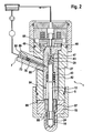
- Fig. 1 is a trained as a common rail injector fuel injector 1 for injecting fuel in a combustion chamber, not shown, of an internal combustion engine of a motor vehicle.
- a high pressure pump 2 delivers fuel from a reservoir 3 into a high-pressure fuel accumulator 4 (rail). In this fuel, especially diesel or gasoline, under high pressure, of about 2500 bar in this embodiment, stored.
- the fuel injector 1 is connected, among other injectors, not shown, via a supply line 5.
- This supply line 5 leads to a fuel supply port 6 with a fuel supply channel 7.
- the fuel supply port 6 and the fuel supply channel 7 are formed on or in a sleeve part 70, which with an end-side external thread 71 in a corresponding internal thread 72 of a Injector body 19 (housing part) is screwed.
- a high-pressure port 73 is pressed, through which the fuel flowing in via the fuel supply port 6 from the high-pressure fuel accumulator 4 fuel flow directly into a central, designed as a mini-rail, high-pressure chamber 8.
- the high-pressure chamber 8 there is essentially rail pressure of about 2500 bar.
- a fuel return port 10 injector return port
- a return line 11 is connected.
- a one-piece injection valve element 13 is received in an axially adjustable manner in the embodiment shown.
- the injection valve element 13 is designed in several parts and consists for example of an upper control rod and a lower nozzle needle.
- the injection valve element 13 is guided longitudinally displaceable in a guide bore 14 of a lower nozzle body 15 in the drawing plane.
- axial channels 16 are realized on the outer circumference of the injection valve element 13 in the region of its lower guide as polished sections, via which the fuel can flow in the axial direction down to a nozzle hole arrangement 17 when the injection valve element 13 is open.
- the nozzle body 15 is clamped by means of a union nut 18 with the injector body 19.
- the injector body 19 forms the largest housing part of a housing 20.
- the injection valve element 13 has at its tip 21 a closing surface 22, with which the injection valve element 13 can be brought into tight contact with an injection valve element seat 23 formed inside the nozzle body 15.
- an injection valve element seat 23 formed inside the nozzle body 15.
- the injection valve element 13 abuts against its injection valve element seat 23, ie is in a closed position, the fuel outlet from the nozzle hole arrangement 17 is blocked. If, on the other hand, it is lifted off its injection valve element seat 23, fuel can flow from the high-pressure chamber 8 in the axial direction via the axial channels 16 into a lower nozzle space 24 formed as an annular space and from there past the injection valve element 13 to the nozzle hole arrangement 17 and there substantially under high pressure (FIG. Rail pressure) standing in the combustion chamber (not shown) to be injected.
- FOG. Rail pressure high pressure standing in the combustion chamber
- the nozzle chamber 24 is a part of the high-pressure chamber 8, in which, in the case that the axial channels 16 are formed as throttle channels, a slightly lower pressure than in the upper, larger part of the high-pressure chamber 8, thus with a closed injection valve element 13 is a hydraulic closing force component to generate the injection valve element 13.
- a control chamber 28 is limited, which is supplied via a designed as a radial bore in the injector component 27 inlet throttle 29 with fuel from the high-pressure chamber 8.
- the control chamber 28 is connected to a valve chamber 32 of a control valve 33 (servo valve) via an outlet channel 30 extending axially in the injector component 27 with outlet throttle 31.
- the valve chamber 32 is bounded radially on the outside by a sleeve-shaped control valve element 34.
- the sleeve-shaped control valve element 34 is substantially pressure balanced in its closed position in the axial direction.
- valve chamber 32 is bounded in the axial upward direction by a pressure pin 35, which is supported axially on the injector 9 and as of the Injektorbauteil 27 is formed separate component.
- the sleeve-shaped control valve element 34 is integrally formed with an anchor plate 37 which cooperates with an electromagnetic actuator 38. When this is energized, the sleeve-shaped control valve member 34 lifts in the axial direction of its control valve seat 36 so that fuel from the valve chamber 32 and subsequently from the control chamber 28 in the low pressure region 12 and from there via the fuel return port 10 and the return line 11 for Can reservoir 3 flow.
- the flow cross-sections of the inlet throttle 29 and the outlet throttle 31 are coordinated such that when open control valve 33, a net outflow of fuel from the control chamber 28 results, with the result that the fuel pressure in the control chamber 28 drops rapidly and thus a hydraulic opening force on the Injection valve element 13 acts, which lifts in the sequence of its injection valve element seat 23 and the nozzle hole assembly 17 for injecting fuel into the combustion chamber releases.
- the energization of the electromagnetic actuator 38 is interrupted. With a one end on a shoulder of the pressure pin 35 and the other end on an upper end side of the armature plate 37 supporting the control closing spring 39, the sleeve-shaped control valve element 34 is moved back to its control valve seat 36.
- the fuel flowing in through the inlet throttle 29 ensures an increase in pressure in the control chamber 28, with the result that the injection valve member 13 is supported by a closing spring 40 is moved back to the injection valve element seat 23.
- the closing spring 40 is arranged in the high-pressure chamber 8 and is supported at one end on a lower end face of the injector component 27 and at the other end on a circumferential collar 41 of the injection valve element 13.
- the axial channels 16, as mentioned above, can be formed as throttle channels, thus reducing the pressure in the nozzle chamber 24 somewhat.
- the pressure is preferably reduced only about 100 to 200 bar, so that the nozzle chamber 24 and the high-pressure chamber 8 can be considered substantially as a common space.
- a pressure surge Joukowski shock
- the resulting peak pressures can be several 100 bar above the maximum rail pressure, whereby the entire fuel injector 1 and the supply system must be designed according to the peak pressures.
- Fig. 1 shows fuel injector 1 an annular space 42 before, which is located radially between the high-pressure chamber 8 and the injector body.
- the annulus 42 extends axially over only a small part of the axial extent of the injector body 19. Axial below and axially above the annular space 42 is under high pressure (substantially rail pressure) stationary fuel.
- the annular space 42 is bounded radially inwards with respect to the high-pressure chamber 8 by a tubular portion 43 of the injector component 27.
- a stepped bore 44 is introduced for this purpose, which limits the control chamber 28 in its upper end in the drawing plane.
- the pressure in the annular space 42 prevails during injector operation permanently lower fuel pressure than in the high pressure chamber 8 and permanently higher fuel pressure than in the low pressure region 12 of the fuel injector 1. Due to the provision of a throttle arrangement to be explained below, the pressure in the annular space 42 is permanently lower than in the high-pressure chamber 8.
- the flow cross-sections of the below-mentioned still to be explained throttles of the mentioned throttle assembly are coordinated so that the fuel pressure in the annular space 42 does not exceed about 1800 bar. As a result, the pressure load of the injector body 19 or the component intersection 74 is reduced.
- a diameter-reduced portion 77 axially adjacent to the thickened portion 76 extends obliquely inward in the radial direction and engages with a tapered end 78 in a conically tapering radially inward direction Opening 79 of the tubular portion 43 of the Injektorbauteils 27.
- the tapered opening 79 opens into a region of the high-pressure chamber 8 radially between the injection valve member 13 and the tubular portion 43 of the Injektorbauteils 27.
- the annular space 42 is separated from the high-pressure region of the injector in both axial directions by a respective sealing element 50, the sealing elements 50 being located radially between the tubular section 43 of the injector component 27 and the inner circumference of the injector body 19.
- FIG. 1 shown Injektorbauteil 27 does not necessarily have to be made in one piece.
- annular space 42 with an independent, tubular element, which in the embodiment shown is formed by the tubular portion 43 of the injector component 27.
- a tubular element is supported in the axial direction on a separate plate element designed here as a plate section 47 of the injector component 27, which delimits the low-pressure region 12 of the fuel injector 1 in the axial direction downwards.
- the actual high-pressure chamber 8 is hydraulically connected via a throttle-free connection channel 81, which is provided in the tubular portion 43 of the Injektorbauteils 27, with a high-pressure annulus 82 which is located in the plane above the annular space 42 and the plate section 47 of the injector component 27 is adjacent in an axially upper region.
- the high pressure annulus 82 encloses an upper guide 83 for the injection valve element 13 radially outward and thus prevents widening of the guide gap of the guide 83 during operation of the fuel injector 1, whereby the leakage amount is reduced.
- Fig. 1 yields, under the high pressure of in the illustrated embodiment, 2500 bar standing fuel in the radial direction via an annular space inlet throttle 51 into the annular space 42 to flow.
- the annular space inlet throttle 51 is designed in the embodiment shown as a throttle bore 84 which is introduced radially into the tubular portion 43. From the throttle bore 84 opens a vertically upwardly extending throttle bore 85, in which an annular space flow restrictor 52 is realized, can flow through the fuel from the annular space 42 in the axial direction upwards in the low pressure region 12 of the fuel injector 1.
- the flow cross-sections of the annular space inlet throttle 51 and the annular space drain throttle 52 are coordinated so that the pressure in the annular space 42, as explained above, does not exceed a maximum pressure of 1800 bar, whereby the pressure load of the injector body 19 is significantly reduced in the area of component intersection 74.
- the annular space inlet throttle 51 and the annular space outlet throttle 52 are designed as throttle bores 84, 85, alternative production possibilities also being able to be realized. Since the pressure in the annular space 42 has no influence on the injection behavior of the fuel injector 1, the annular space inlet throttle 51 and the annular space drain throttle 52 are made very small, whereby the necessary for the pressure reduction, parasitic flow rate is low. On the other hand, the pressure in the pressure chamber 42 does not react to highly dynamic pressure changes in the high-pressure space 8 serving as a mini-rail, but only to function-related rail pressure changes.
- 87 are formed on the outer circumference of the tubular member 87, which do not form with the inner circumference in the embodiment shown as a guide for the injection valve element 13 serving guide bore 14 corresponding axial channels.
- a sealing of the annular space 42 in the axial direction upwards and downwards is ensured by a valve clamping screw 48, which biases the injector component 27 in the axial direction upward, such that the plate portion 47 tightly abuts an annular shoulder 49 of the injector body 19 and the lower end of Pipe part 87 rests tightly against the nozzle body 15.
- the pressure in the annular space 42 in the embodiment according to Fig. 3 is not permanently reduced compared to the high-pressure chamber 8. This is due to the fact that the fuel from the annular space 42 can flow only temporarily in the low-pressure region 12 of the fuel injector 1.
- the influx from the high-pressure chamber 8 in the annular space 42 is also in the in Fig. 3 shown embodiment via a designed as a throttle bore 84 annular space inlet throttle 51. This opens into the annular space 42, in contrast to the embodiment according to Fig. 1 in the axial direction up to the plate portion 47 extends.
- the annular space drain throttle 52 is in the embodiment according to Fig.
- the overpressure valve 53 comprises a valve element 54 in the form of a steel ball which is spring-loaded by a spring 55 designed as a leaf spring in the direction of a valve seat 56 formed on the injector component 27, more precisely on the plate section 47.
- a spring 55 designed as a leaf spring in the direction of a valve seat 56 formed on the injector component 27, more precisely on the plate section 47.
- the underside of the valve element 54 via a channel 46 in the injector component 27 permanently in communication with the annulus volume of the annular space 42. If the pressure in the annular space 42 exceeds said minimum pressure, the spherical valve element 54 is lifted against its spring force 55 of its valve seat 56 , so that the fuel throttled from the annular space 42 can flow into the low-pressure region 12.
- the pressure relief valve 53 is dimensioned so that the throttling action of the pressure relief valve 53 (annulus drain) has the desired level of pressure reduction in the annular space 42 result.
- FIG. 3 shows, designed as a leaf spring spring 55 is clamped axially between the valve clamping screw 48 and the upper side in the drawing plane of the plate portion 47 of the Injektorbauteils 27th
- FIG. 4 shown embodiment of a fuel injector 1 works on the same principle as in Fig. 3 shown and previously described embodiment. Also in the embodiment according to Fig. 4 If no throttle channel is provided as annular space drain throttle 52. This is formed by the pressure relief valve 53 via which the annular space 42 with the low pressure region 12 of the fuel injector 1 is connectable. The valve element 54 is formed by the plate portion 47 of the Injektorbauteils 27. This is in the closed state of the pressure relief valve 53 on the annular shoulder 49 of the injector body 9 on.
- the plate section 47 When the overpressure valve 53 is open, the plate section 47 is adjusted in the axial direction upward, so that an annular gap is formed axially between the plate section 47 and a biting edge 45 of the injector body 19, wherein the flow cross-section of the annular gap is adjusted so that the desired throttle is achieved.
- the plate section 47 only lifts off from its valve seat 56 formed by the biting edge 45 on the injector body 19 when the pressure force acting on it exceeds the spring force of a spring 55 designed as a plate spring, which is supported in the axial direction upward on the valve clamping screw 48.
- the spring 55 tends to press the plate portion 47 axially downwardly against the annular shoulder 49 of the injector body 19.
Claims (12)
- Injecteur de carburant, en particulier injecteur à rampe commune, pour l'injection de carburant dans une chambre de combustion d'un moteur à combustion interne, comprenant un conduit d'alimentation en carburant (7), avec un raccord de retour de carburant (10) et avec un élément de soupape d'injection (13) d'une seule pièce ou en plusieurs parties, déplaçable entre une position d'ouverture et une position de fermeture, qui est disposé au moins en partie dans un espace haute pression (8) prévu dans le corps d'injecteur (19),
caractérisé en ce que
le conduit d'alimentation en carburant (7) est connecté par le biais d'une tubulure haute pression en forme de douille (73) à l'espace haute pression (8) et surmonte en l'occurrence un espace annulaire (42) disposé radialement entre le corps d'injecteur (19) et l'espace haute pression (8), dans lequel espace annulaire (42) la pression de carburant pendant le fonctionnement de l'injecteur de carburant (1), au moins temporairement, est inférieure à la pression de carburant dans l'espace haute pression (8) et est supérieure à la pression de carburant au niveau du raccord de retour de carburant (10). - Injecteur de carburant selon la revendication 1, caractérisé en ce que
la tubulure haute pression (73) est en partie reçue dans le conduit d'alimentation en carburant (7). - Injecteur de carburant selon l'une quelconque des revendications 1 ou 2,
caractérisé en ce que
la tubulure haute pression (73) est fixée au moyen d'un ajustement serré ou par vissage ou par soudage dans le conduit d'alimentation en carburant (7). - Injecteur de carburant selon l'une quelconque des revendications précédentes,
caractérisé en ce que
la tubulure haute pression (73) s'étend radialement jusque dans une ouverture (79) dans un composant d'injecteur (27) limitant radialement à l'intérieur l'espace annulaire (42). - Injecteur de carburant selon l'une quelconque des revendications précédentes,
caractérisé en ce que
la tubulure haute pression (73) est réalisée sous forme de filtre à carburant. - Injecteur de carburant selon l'une quelconque des revendications précédentes,
caractérisé en ce que
l'espace annulaire (42) n'est disposé essentiellement que dans la région radialement à l'intérieur d'une portion de corps d'injecteur sensible à la pression, de préférence dans la région d'une intersection de composant (74). - Injecteur de carburant selon l'une quelconque des revendications précédentes,
caractérisé en ce que
l'espace haute pression (8) est connecté hydrauliquement à un espace annulaire haute pression (82) disposé axialement au-dessus de l'espace annulaire (42). - Injecteur de carburant selon l'une quelconque des revendications précédentes,
caractérisé en ce que
l'espace annulaire (42) s'étend axialement jusque dans un corps de buse (15) présentant un agencement de trou d'injection (17). - Injecteur de carburant selon l'une quelconque des revendications précédentes,
caractérisé en ce que
l'espace annulaire (42) peut être alimenté en carburant à haute pression par le biais d'un étranglement d'amenée de l'espace annulaire (51). - Injecteur de carburant selon l'une quelconque des revendications précédentes,
caractérisé en ce que
l'espace annulaire (42) est connecté à une région basse pression (12) de l'injecteur de carburant (1) par le biais d'au moins un étranglement de sortie de l'espace annulaire (52). - Injecteur de carburant selon l'une quelconque des revendications précédentes,
caractérisé en ce que
la pression dans l'espace annulaire (42), par comparaison avec la pression dans l'espace haute pression (8), est réduite seulement à partir du dépassement d'une pression minimale dans l'espace annulaire (42), notamment de plus de 1800 bar. - Injecteur de carburant selon l'une quelconque des revendications précédentes,
caractérisé en ce que
l'espace annulaire (42) peut être connecté hydrauliquement par le biais d'au moins une soupape de surpression (53), notamment réalisée sous forme de clapet antiretour, à la région basse pression (12) de l'injecteur de carburant (1).
Applications Claiming Priority (1)
| Application Number | Priority Date | Filing Date | Title |
|---|---|---|---|
| DE102008002528A DE102008002528A1 (de) | 2008-06-19 | 2008-06-19 | Kraftstoff-Injektor |
Publications (2)
| Publication Number | Publication Date |
|---|---|
| EP2138704A1 EP2138704A1 (fr) | 2009-12-30 |
| EP2138704B1 true EP2138704B1 (fr) | 2011-04-27 |
Family
ID=41279483
Family Applications (1)
| Application Number | Title | Priority Date | Filing Date |
|---|---|---|---|
| EP09100245A Not-in-force EP2138704B1 (fr) | 2008-06-19 | 2009-04-22 | Injecteur de carburant |
Country Status (3)
| Country | Link |
|---|---|
| EP (1) | EP2138704B1 (fr) |
| AT (1) | ATE507387T1 (fr) |
| DE (2) | DE102008002528A1 (fr) |
Families Citing this family (2)
| Publication number | Priority date | Publication date | Assignee | Title |
|---|---|---|---|---|
| DE102014007130B3 (de) * | 2014-05-16 | 2015-10-15 | Audi Ag | Elektromagnetventil für ein Hydrauliksystem |
| DE102017217991A1 (de) | 2017-10-10 | 2019-04-11 | Robert Bosch Gmbh | Injektor zum Dosieren eines Fluids unter hohem Druck und Verfahren zum Betreiben eines solchen Injektors |
Citations (1)
| Publication number | Priority date | Publication date | Assignee | Title |
|---|---|---|---|---|
| DE102007021330A1 (de) * | 2007-05-07 | 2008-11-13 | Robert Bosch Gmbh | Kraftstoffinjektor für eine Brennkraftmaschine mit Common-Rail-Einspritzsystem |
Family Cites Families (5)
| Publication number | Priority date | Publication date | Assignee | Title |
|---|---|---|---|---|
| GB8626652D0 (en) * | 1986-11-07 | 1986-12-10 | Lucas Ind Plc | Fuel injection nozzle |
| DE10133450A1 (de) * | 2001-07-10 | 2003-01-30 | Bosch Gmbh Robert | Magnetventil mit Steck-Drehverbindung |
| DE102004046888A1 (de) * | 2004-09-28 | 2006-03-30 | Robert Bosch Gmbh | Injektor zur Kraftstoffeinspritzung an einer Brennkraftmaschine |
| DE102006014244A1 (de) * | 2006-03-28 | 2007-10-04 | Robert Bosch Gmbh | Kraftstoffinjektor mit Servomagnetventil |
| DE102006054063A1 (de) * | 2006-11-16 | 2008-05-21 | Robert Bosch Gmbh | Kraftstoffinjektor |
-
2008
- 2008-06-19 DE DE102008002528A patent/DE102008002528A1/de not_active Withdrawn
-
2009
- 2009-04-22 AT AT09100245T patent/ATE507387T1/de active
- 2009-04-22 DE DE502009000576T patent/DE502009000576D1/de active Active
- 2009-04-22 EP EP09100245A patent/EP2138704B1/fr not_active Not-in-force
Patent Citations (1)
| Publication number | Priority date | Publication date | Assignee | Title |
|---|---|---|---|---|
| DE102007021330A1 (de) * | 2007-05-07 | 2008-11-13 | Robert Bosch Gmbh | Kraftstoffinjektor für eine Brennkraftmaschine mit Common-Rail-Einspritzsystem |
Also Published As
| Publication number | Publication date |
|---|---|
| ATE507387T1 (de) | 2011-05-15 |
| DE102008002528A1 (de) | 2009-12-24 |
| DE502009000576D1 (de) | 2011-06-09 |
| EP2138704A1 (fr) | 2009-12-30 |
Similar Documents
| Publication | Publication Date | Title |
|---|---|---|
| DE19706591A1 (de) | Druckventil | |
| DE102007001363A1 (de) | Injektor zum Einspritzen von Kraftstoff in Brennräume von Brennkraftmaschinen | |
| EP2294309B1 (fr) | Injecteur de carburant | |
| DE19910589C2 (de) | Einspritzventil für eine Brennkraftmaschine | |
| EP2235356B1 (fr) | Injecteur de carburant | |
| EP2310662B1 (fr) | Injecteur de carburant | |
| DE10335059A1 (de) | Schaltventil für einen Kraftstoffinjektor mit Druckübersetzer | |
| EP1918570B1 (fr) | Injecteur de carburant doté d'un segment de volume de stockage | |
| DE102006009659A1 (de) | Kraftstoff-Einspritzvorrichtung für eine Brennkraftmaschine mit Kraftstoff-Direkteinspritzung | |
| EP2138704B1 (fr) | Injecteur de carburant | |
| DE102008001907A1 (de) | Kraftstoff-Injektor | |
| EP2511514B1 (fr) | Soupape d'injection de combustible | |
| EP1483499B1 (fr) | Systeme pour moduler en pression le comportement d'injection | |
| DE102007005382A1 (de) | Leckagefreier Injektor | |
| DE102006050033A1 (de) | Injektor, insbesondere Common-Rail-Injektor | |
| DE10160490B4 (de) | Kraftstoff-Einspritzvorrichtung, Kraftstoffsystem sowie Brennkraftmaschine | |
| DE10148350A1 (de) | Kraftstoff-Einspritzvorrichtung, insbesondere Injektor für Brennkraftmaschinen mit Direkteinspritzung, sowie Kraftstoffsystem und Brennkraftmaschine | |
| DE102009000283A1 (de) | Injektor zum Einspritzen von Kraftstoff | |
| DE102007001365A1 (de) | Injektor mit Steuer- und Schaltkammer | |
| DE19947196A1 (de) | Kraftstoffeinspritzeinrichtung für Brennkraftmaschinen | |
| DE102021202731A1 (de) | Kraftstoffeinspritzeinrichtung | |
| DE102008001600A1 (de) | Kraftstoff-Injektor mit einem eine Druckstufe aufweisenden Steuerventil | |
| EP2085604A1 (fr) | Injecteur de carburant | |
| WO2008095743A1 (fr) | Injecteur pour injecter du carburant dans des chambres de combustion de moteurs à combustion interne | |
| DE102007018042A1 (de) | Injektor mit mehrteiligem Ventilelement |
Legal Events
| Date | Code | Title | Description |
|---|---|---|---|
| PUAI | Public reference made under article 153(3) epc to a published international application that has entered the european phase |
Free format text: ORIGINAL CODE: 0009012 |
|
| AK | Designated contracting states |
Kind code of ref document: A1 Designated state(s): AT BE BG CH CY CZ DE DK EE ES FI FR GB GR HR HU IE IS IT LI LT LU LV MC MK MT NL NO PL PT RO SE SI SK TR |
|
| 17P | Request for examination filed |
Effective date: 20100630 |
|
| 17Q | First examination report despatched |
Effective date: 20100803 |
|
| RIC1 | Information provided on ipc code assigned before grant |
Ipc: F02M 47/02 20060101AFI20101201BHEP Ipc: F02M 63/02 20060101ALI20101201BHEP Ipc: F02M 55/00 20060101ALI20101201BHEP Ipc: F02M 61/16 20060101ALI20101201BHEP Ipc: F02M 63/00 20060101ALI20101201BHEP |
|
| GRAP | Despatch of communication of intention to grant a patent |
Free format text: ORIGINAL CODE: EPIDOSNIGR1 |
|
| GRAS | Grant fee paid |
Free format text: ORIGINAL CODE: EPIDOSNIGR3 |
|
| GRAA | (expected) grant |
Free format text: ORIGINAL CODE: 0009210 |
|
| AK | Designated contracting states |
Kind code of ref document: B1 Designated state(s): AT BE BG CH CY CZ DE DK EE ES FI FR GB GR HR HU IE IS IT LI LT LU LV MC MK MT NL NO PL PT RO SE SI SK TR |
|
| REG | Reference to a national code |
Ref country code: GB Ref legal event code: FG4D Free format text: NOT ENGLISH |
|
| REG | Reference to a national code |
Ref country code: CH Ref legal event code: EP |
|
| REG | Reference to a national code |
Ref country code: IE Ref legal event code: FG4D Free format text: LANGUAGE OF EP DOCUMENT: GERMAN |
|
| REF | Corresponds to: |
Ref document number: 502009000576 Country of ref document: DE Date of ref document: 20110609 Kind code of ref document: P |
|
| REG | Reference to a national code |
Ref country code: DE Ref legal event code: R096 Ref document number: 502009000576 Country of ref document: DE Effective date: 20110609 |
|
| REG | Reference to a national code |
Ref country code: NL Ref legal event code: VDEP Effective date: 20110427 |
|
| LTIE | Lt: invalidation of european patent or patent extension |
Effective date: 20110427 |
|
| PG25 | Lapsed in a contracting state [announced via postgrant information from national office to epo] |
Ref country code: HR Free format text: LAPSE BECAUSE OF FAILURE TO SUBMIT A TRANSLATION OF THE DESCRIPTION OR TO PAY THE FEE WITHIN THE PRESCRIBED TIME-LIMIT Effective date: 20110427 Ref country code: SE Free format text: LAPSE BECAUSE OF FAILURE TO SUBMIT A TRANSLATION OF THE DESCRIPTION OR TO PAY THE FEE WITHIN THE PRESCRIBED TIME-LIMIT Effective date: 20110427 Ref country code: PT Free format text: LAPSE BECAUSE OF FAILURE TO SUBMIT A TRANSLATION OF THE DESCRIPTION OR TO PAY THE FEE WITHIN THE PRESCRIBED TIME-LIMIT Effective date: 20110829 Ref country code: LT Free format text: LAPSE BECAUSE OF FAILURE TO SUBMIT A TRANSLATION OF THE DESCRIPTION OR TO PAY THE FEE WITHIN THE PRESCRIBED TIME-LIMIT Effective date: 20110427 Ref country code: NO Free format text: LAPSE BECAUSE OF FAILURE TO SUBMIT A TRANSLATION OF THE DESCRIPTION OR TO PAY THE FEE WITHIN THE PRESCRIBED TIME-LIMIT Effective date: 20110727 |
|
| REG | Reference to a national code |
Ref country code: IE Ref legal event code: FD4D |
|
| PG25 | Lapsed in a contracting state [announced via postgrant information from national office to epo] |
Ref country code: LV Free format text: LAPSE BECAUSE OF FAILURE TO SUBMIT A TRANSLATION OF THE DESCRIPTION OR TO PAY THE FEE WITHIN THE PRESCRIBED TIME-LIMIT Effective date: 20110427 Ref country code: ES Free format text: LAPSE BECAUSE OF FAILURE TO SUBMIT A TRANSLATION OF THE DESCRIPTION OR TO PAY THE FEE WITHIN THE PRESCRIBED TIME-LIMIT Effective date: 20110807 Ref country code: SI Free format text: LAPSE BECAUSE OF FAILURE TO SUBMIT A TRANSLATION OF THE DESCRIPTION OR TO PAY THE FEE WITHIN THE PRESCRIBED TIME-LIMIT Effective date: 20110427 Ref country code: GR Free format text: LAPSE BECAUSE OF FAILURE TO SUBMIT A TRANSLATION OF THE DESCRIPTION OR TO PAY THE FEE WITHIN THE PRESCRIBED TIME-LIMIT Effective date: 20110728 Ref country code: IS Free format text: LAPSE BECAUSE OF FAILURE TO SUBMIT A TRANSLATION OF THE DESCRIPTION OR TO PAY THE FEE WITHIN THE PRESCRIBED TIME-LIMIT Effective date: 20110827 Ref country code: FI Free format text: LAPSE BECAUSE OF FAILURE TO SUBMIT A TRANSLATION OF THE DESCRIPTION OR TO PAY THE FEE WITHIN THE PRESCRIBED TIME-LIMIT Effective date: 20110427 Ref country code: CY Free format text: LAPSE BECAUSE OF FAILURE TO SUBMIT A TRANSLATION OF THE DESCRIPTION OR TO PAY THE FEE WITHIN THE PRESCRIBED TIME-LIMIT Effective date: 20110427 |
|
| PG25 | Lapsed in a contracting state [announced via postgrant information from national office to epo] |
Ref country code: NL Free format text: LAPSE BECAUSE OF FAILURE TO SUBMIT A TRANSLATION OF THE DESCRIPTION OR TO PAY THE FEE WITHIN THE PRESCRIBED TIME-LIMIT Effective date: 20110427 |
|
| PG25 | Lapsed in a contracting state [announced via postgrant information from national office to epo] |
Ref country code: CZ Free format text: LAPSE BECAUSE OF FAILURE TO SUBMIT A TRANSLATION OF THE DESCRIPTION OR TO PAY THE FEE WITHIN THE PRESCRIBED TIME-LIMIT Effective date: 20110427 Ref country code: EE Free format text: LAPSE BECAUSE OF FAILURE TO SUBMIT A TRANSLATION OF THE DESCRIPTION OR TO PAY THE FEE WITHIN THE PRESCRIBED TIME-LIMIT Effective date: 20110427 Ref country code: IE Free format text: LAPSE BECAUSE OF FAILURE TO SUBMIT A TRANSLATION OF THE DESCRIPTION OR TO PAY THE FEE WITHIN THE PRESCRIBED TIME-LIMIT Effective date: 20110427 |
|
| PG25 | Lapsed in a contracting state [announced via postgrant information from national office to epo] |
Ref country code: PL Free format text: LAPSE BECAUSE OF FAILURE TO SUBMIT A TRANSLATION OF THE DESCRIPTION OR TO PAY THE FEE WITHIN THE PRESCRIBED TIME-LIMIT Effective date: 20110427 Ref country code: DK Free format text: LAPSE BECAUSE OF FAILURE TO SUBMIT A TRANSLATION OF THE DESCRIPTION OR TO PAY THE FEE WITHIN THE PRESCRIBED TIME-LIMIT Effective date: 20110427 Ref country code: RO Free format text: LAPSE BECAUSE OF FAILURE TO SUBMIT A TRANSLATION OF THE DESCRIPTION OR TO PAY THE FEE WITHIN THE PRESCRIBED TIME-LIMIT Effective date: 20110427 Ref country code: SK Free format text: LAPSE BECAUSE OF FAILURE TO SUBMIT A TRANSLATION OF THE DESCRIPTION OR TO PAY THE FEE WITHIN THE PRESCRIBED TIME-LIMIT Effective date: 20110427 |
|
| PLBE | No opposition filed within time limit |
Free format text: ORIGINAL CODE: 0009261 |
|
| STAA | Information on the status of an ep patent application or granted ep patent |
Free format text: STATUS: NO OPPOSITION FILED WITHIN TIME LIMIT |
|
| 26N | No opposition filed |
Effective date: 20120130 |
|
| REG | Reference to a national code |
Ref country code: DE Ref legal event code: R097 Ref document number: 502009000576 Country of ref document: DE Effective date: 20120130 |
|
| PGFP | Annual fee paid to national office [announced via postgrant information from national office to epo] |
Ref country code: FR Payment date: 20120511 Year of fee payment: 4 |
|
| PGFP | Annual fee paid to national office [announced via postgrant information from national office to epo] |
Ref country code: IT Payment date: 20120430 Year of fee payment: 4 |
|
| BERE | Be: lapsed |
Owner name: ROBERT BOSCH G.M.B.H. Effective date: 20120430 |
|
| PG25 | Lapsed in a contracting state [announced via postgrant information from national office to epo] |
Ref country code: MC Free format text: LAPSE BECAUSE OF NON-PAYMENT OF DUE FEES Effective date: 20120430 |
|
| PG25 | Lapsed in a contracting state [announced via postgrant information from national office to epo] |
Ref country code: BE Free format text: LAPSE BECAUSE OF NON-PAYMENT OF DUE FEES Effective date: 20120430 |
|
| PG25 | Lapsed in a contracting state [announced via postgrant information from national office to epo] |
Ref country code: MK Free format text: LAPSE BECAUSE OF FAILURE TO SUBMIT A TRANSLATION OF THE DESCRIPTION OR TO PAY THE FEE WITHIN THE PRESCRIBED TIME-LIMIT Effective date: 20110427 |
|
| PG25 | Lapsed in a contracting state [announced via postgrant information from national office to epo] |
Ref country code: BG Free format text: LAPSE BECAUSE OF FAILURE TO SUBMIT A TRANSLATION OF THE DESCRIPTION OR TO PAY THE FEE WITHIN THE PRESCRIBED TIME-LIMIT Effective date: 20110727 |
|
| PG25 | Lapsed in a contracting state [announced via postgrant information from national office to epo] |
Ref country code: MT Free format text: LAPSE BECAUSE OF FAILURE TO SUBMIT A TRANSLATION OF THE DESCRIPTION OR TO PAY THE FEE WITHIN THE PRESCRIBED TIME-LIMIT Effective date: 20110427 |
|
| REG | Reference to a national code |
Ref country code: CH Ref legal event code: PL |
|
| GBPC | Gb: european patent ceased through non-payment of renewal fee |
Effective date: 20130422 |
|
| PG25 | Lapsed in a contracting state [announced via postgrant information from national office to epo] |
Ref country code: LI Free format text: LAPSE BECAUSE OF NON-PAYMENT OF DUE FEES Effective date: 20130430 Ref country code: GB Free format text: LAPSE BECAUSE OF NON-PAYMENT OF DUE FEES Effective date: 20130422 Ref country code: CH Free format text: LAPSE BECAUSE OF NON-PAYMENT OF DUE FEES Effective date: 20130430 |
|
| REG | Reference to a national code |
Ref country code: FR Ref legal event code: ST Effective date: 20131231 |
|
| PG25 | Lapsed in a contracting state [announced via postgrant information from national office to epo] |
Ref country code: IT Free format text: LAPSE BECAUSE OF NON-PAYMENT OF DUE FEES Effective date: 20130422 Ref country code: FR Free format text: LAPSE BECAUSE OF NON-PAYMENT OF DUE FEES Effective date: 20130430 |
|
| PG25 | Lapsed in a contracting state [announced via postgrant information from national office to epo] |
Ref country code: TR Free format text: LAPSE BECAUSE OF FAILURE TO SUBMIT A TRANSLATION OF THE DESCRIPTION OR TO PAY THE FEE WITHIN THE PRESCRIBED TIME-LIMIT Effective date: 20110427 |
|
| PG25 | Lapsed in a contracting state [announced via postgrant information from national office to epo] |
Ref country code: LU Free format text: LAPSE BECAUSE OF NON-PAYMENT OF DUE FEES Effective date: 20120422 |
|
| PG25 | Lapsed in a contracting state [announced via postgrant information from national office to epo] |
Ref country code: HU Free format text: LAPSE BECAUSE OF FAILURE TO SUBMIT A TRANSLATION OF THE DESCRIPTION OR TO PAY THE FEE WITHIN THE PRESCRIBED TIME-LIMIT Effective date: 20090422 |
|
| REG | Reference to a national code |
Ref country code: AT Ref legal event code: MM01 Ref document number: 507387 Country of ref document: AT Kind code of ref document: T Effective date: 20140422 |
|
| PG25 | Lapsed in a contracting state [announced via postgrant information from national office to epo] |
Ref country code: AT Free format text: LAPSE BECAUSE OF NON-PAYMENT OF DUE FEES Effective date: 20140422 |
|
| PGFP | Annual fee paid to national office [announced via postgrant information from national office to epo] |
Ref country code: DE Payment date: 20190627 Year of fee payment: 11 |
|
| REG | Reference to a national code |
Ref country code: DE Ref legal event code: R119 Ref document number: 502009000576 Country of ref document: DE |
|
| PG25 | Lapsed in a contracting state [announced via postgrant information from national office to epo] |
Ref country code: DE Free format text: LAPSE BECAUSE OF NON-PAYMENT OF DUE FEES Effective date: 20201103 |