EP2085604A1 - Fuel injector - Google Patents
Fuel injector Download PDFInfo
- Publication number
- EP2085604A1 EP2085604A1 EP09100054A EP09100054A EP2085604A1 EP 2085604 A1 EP2085604 A1 EP 2085604A1 EP 09100054 A EP09100054 A EP 09100054A EP 09100054 A EP09100054 A EP 09100054A EP 2085604 A1 EP2085604 A1 EP 2085604A1
- Authority
- EP
- European Patent Office
- Prior art keywords
- valve element
- injection valve
- throttle channel
- injector
- chamber
- Prior art date
- Legal status (The legal status is an assumption and is not a legal conclusion. Google has not performed a legal analysis and makes no representation as to the accuracy of the status listed.)
- Withdrawn
Links
Images
Classifications
-
- F—MECHANICAL ENGINEERING; LIGHTING; HEATING; WEAPONS; BLASTING
- F02—COMBUSTION ENGINES; HOT-GAS OR COMBUSTION-PRODUCT ENGINE PLANTS
- F02M—SUPPLYING COMBUSTION ENGINES IN GENERAL WITH COMBUSTIBLE MIXTURES OR CONSTITUENTS THEREOF
- F02M47/00—Fuel-injection apparatus operated cyclically with fuel-injection valves actuated by fluid pressure
- F02M47/02—Fuel-injection apparatus operated cyclically with fuel-injection valves actuated by fluid pressure of accumulator-injector type, i.e. having fuel pressure of accumulator tending to open, and fuel pressure in other chamber tending to close, injection valves and having means for periodically releasing that closing pressure
- F02M47/027—Electrically actuated valves draining the chamber to release the closing pressure
-
- F—MECHANICAL ENGINEERING; LIGHTING; HEATING; WEAPONS; BLASTING
- F02—COMBUSTION ENGINES; HOT-GAS OR COMBUSTION-PRODUCT ENGINE PLANTS
- F02M—SUPPLYING COMBUSTION ENGINES IN GENERAL WITH COMBUSTIBLE MIXTURES OR CONSTITUENTS THEREOF
- F02M61/00—Fuel-injectors not provided for in groups F02M39/00 - F02M57/00 or F02M67/00
- F02M61/04—Fuel-injectors not provided for in groups F02M39/00 - F02M57/00 or F02M67/00 having valves, e.g. having a plurality of valves in series
- F02M61/10—Other injectors with elongated valve bodies, i.e. of needle-valve type
- F02M61/12—Other injectors with elongated valve bodies, i.e. of needle-valve type characterised by the provision of guiding or centring means for valve bodies
-
- F—MECHANICAL ENGINEERING; LIGHTING; HEATING; WEAPONS; BLASTING
- F02—COMBUSTION ENGINES; HOT-GAS OR COMBUSTION-PRODUCT ENGINE PLANTS
- F02M—SUPPLYING COMBUSTION ENGINES IN GENERAL WITH COMBUSTIBLE MIXTURES OR CONSTITUENTS THEREOF
- F02M2547/00—Special features for fuel-injection valves actuated by fluid pressure
- F02M2547/001—Control chambers formed by movable sleeves
-
- F—MECHANICAL ENGINEERING; LIGHTING; HEATING; WEAPONS; BLASTING
- F02—COMBUSTION ENGINES; HOT-GAS OR COMBUSTION-PRODUCT ENGINE PLANTS
- F02M—SUPPLYING COMBUSTION ENGINES IN GENERAL WITH COMBUSTIBLE MIXTURES OR CONSTITUENTS THEREOF
- F02M2547/00—Special features for fuel-injection valves actuated by fluid pressure
- F02M2547/008—Means for influencing the flow rate out of or into a control chamber, e.g. depending on the position of the needle
-
- F—MECHANICAL ENGINEERING; LIGHTING; HEATING; WEAPONS; BLASTING
- F02—COMBUSTION ENGINES; HOT-GAS OR COMBUSTION-PRODUCT ENGINE PLANTS
- F02M—SUPPLYING COMBUSTION ENGINES IN GENERAL WITH COMBUSTIBLE MIXTURES OR CONSTITUENTS THEREOF
- F02M63/00—Other fuel-injection apparatus having pertinent characteristics not provided for in groups F02M39/00 - F02M57/00 or F02M67/00; Details, component parts, or accessories of fuel-injection apparatus, not provided for in, or of interest apart from, the apparatus of groups F02M39/00 - F02M61/00 or F02M67/00; Combination of fuel pump with other devices, e.g. lubricating oil pump
- F02M63/02—Fuel-injection apparatus having several injectors fed by a common pumping element, or having several pumping elements feeding a common injector; Fuel-injection apparatus having provisions for cutting-out pumps, pumping elements, or injectors; Fuel-injection apparatus having provisions for variably interconnecting pumping elements and injectors alternatively
- F02M63/0225—Fuel-injection apparatus having a common rail feeding several injectors ; Means for varying pressure in common rails; Pumps feeding common rails
Definitions
- the invention relates to an injector, in particular a common rail injector, for injecting fuel in a combustion chamber of an internal combustion engine according to the preamble of claim 1.
- Known injectors include a control valve (servo valve) by means of which the fuel pressure can be influenced within a limited by an injection valve element control chamber.
- a control valve servo valve
- the control chamber is connected to a low-pressure region of the injector via an outlet throttle channel, with the result that the fuel pressure inside the control chamber and thus the closing force acting on the injection valve element drop, whereby the injection valve element is seated from its injection valve element seat lifts and fuel can flow through a nozzle hole arrangement in a combustion chamber of an internal combustion engine.
- the two-part injection valve element on its axially limiting the control chamber end face has a central stop with a flat end face which closes an outlet throttle when the injection valve element is open.
- a guide for the injection valve element and the outlet throttle channel in a common Valve piece formed.
- a disadvantage is the lack of sealing of the outlet throttle channel and a possibly occurring hydraulic sticking of the injection valve element on the valve piece.
- an injector which has an end member provided with a throttle channel at its end face on its injection valve element. Even if the end member rests in the edge region of the mouth of the outlet throttle channel, the control chamber via the throttle channel is still hydraulically connected to the outlet throttle channel.
- the invention has for its object to provide an injector, in which a good seal of the discharge throttle channel can be ensured with an open injection valve element without it being absolutely necessary to center the injection valve element relative to the orifice of a discharge throttle exactly.
- the invention has recognized that in order to minimize the control quantity flowing out of the control chamber in the direction of the injector return, it is advantageous to seal the outlet throttle channel by means of the injection valve element when it is in its open position. So that a good seal of the outlet throttle channel is ensured by the one- or multi-part injection valve element, without having to take care that the guide for the injection valve element and the mouth opening of the outlet throttle channel are aligned exactly, the invention proposes, at the end face of the injection valve element a circumferential, preferably circular, sealing edge (usually biting edge) to provide, which seals the outlet throttle channel in the open position of the injection valve element relative to the (remaining) control chamber.
- one after the Concept of the invention formed injector on the front side of the injection valve element designed as a sealing edge stroke stop provided, which rests with the injection valve element in its open position on a discharge throttle channel receiving component.
- the diameter of the sealing edge is preferably selected to be at most as large as is absolutely necessary in order to securely seal the outlet throttle channel.
- the diameter of the sealing edge should be selected so that when the control valve (servo valve) is open, a sufficiently large excess of force is established on the injection valve element so that it remains open.
- the diameter of the sealing edge is selected so that when the control valve is open, the opening force acting on the injection valve element is greater than the closing force acting on the injection valve element.
- the outlet throttle channel is arranged in a throttle plate axially delimiting the control chamber, wherein the closed sealing edge provided on the end side of the injection valve element surrounds a mouth opening of the outlet throttle channel in the throttle plate radially on the outside.
- the injection valve element in its open position, is supported on the preferably flat (lower, ie the combustion chamber facing) surface of the throttle plate with a radial distance from the outlet opening of the outlet throttle channel.
- a seal of the outlet throttle channel with respect to the control chamber is also achieved when the injection valve element is not aligned exactly with the mouth opening. It is only essential that the mouth opening of the outlet throttle channel is located completely in a region radially within the sealing edge.
- the mouth opening of the outlet throttle channel is, at least approximately, centric with respect to the (extended) longitudinal central axis of the injection valve element, in particular in order to realize a symmetrical component load, is advantageous.
- an embodiment of the injector is possible in which, despite ensuring a seal of the outlet throttle when the injection valve element is open, the control chamber is not bounded radially on the outside by the same component in which the outlet throttle channel is accommodated, but instead by a sleeve which is in axial direction is spring-loaded by means of a spring on the throttle plate.
- the manufacture of the throttle plate is thereby simplified.
- the sleeve is surrounded by under high pressure fuel to minimize the guide gap between the sleeve and the injection valve element.
- the throttle plate is particularly preferably a simple cylinder plate with two parallel end faces, wherein the control chamber adjoins a first (lower) end face and a valve chamber of the control valve at the other (upper) end face.
- the control chamber is supplied with advantage via an inlet throttle channel permanently under high pressure (rail pressure) stagnant fuel.
- the inlet throttle channel is located in the throttle plate.
- the inlet throttle channel is connected via a front-side hydraulic bag with a supply channel in the injector via which a high-pressure chamber of the injector with fuel from a high-pressure fuel storage (rail) is supplied.
- the inlet throttle is introduced into the sleeve, preferably as a radial channel.
- an embodiment of the injector is preferred in which the diameter ratio between the minimum diameter of the outlet throttle channel and the minimum diameter of the inlet throttle channel is selected from a range between about 0.8 and about 0.9. Particularly preferred is an embodiment in which this ratio is about 0.86.
- the end face of the injection valve element is formed radially within the sealing edge of at least two, preferably only two, mutually angularly arranged annular surface portions, wherein preferably immediately adjacent to the sealing edge annular surface portion less strongly relative to a perpendicular from the Intersected with the longitudinal center axis of the injection valve element interspersed plane, as a radially inwardly adjacent to this annular surface portion annular surface portion.
- a valve chamber of the control valve which is hydraulically connected via the outlet throttle with the control chamber, via a connecting channel (bypass) with a high-pressure region of the injector, in particular with a control chamber radially inwardly receiving pressure chamber, connected so that when the control valve is closed, fuel can flow into the valve chamber via the connecting channel and into the control chamber via the outlet throttle channel.
- the control chamber is not only pressurized only via the inlet throttle channel, but also backwards over the outlet throttle channel with high pressure until the force equilibrium is reached at the injection valve element. In this way, an accelerated closing of the injection valve element can be realized.
- control valve is designed as a 3/2-way valve and the connecting channel in a switching position in which the control chamber is hydraulically connected to the low pressure region of the injector, lides preferably with the end face of an axially adjustable bisti ,
- the actuator for actuating the control valve is designed as a piezo actuator.
- This preferably comprises a multiplicity of stacked crystal platelets which expand when energized.
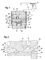
- Fig. 1 is a fragmentary designed as a common rail injector injector 1 for injecting fuel into a combustion chamber of an internal combustion engine (not shown) shown.
- the injector 1 is supplied via a high-pressure supply line 2 from a high-pressure fuel accumulator 3 (rail) with high pressure, in the embodiment shown above 2000 bar, standing fuel, especially diesel.
- the fuel high-pressure accumulator 3 is supplied with fuel from a low-pressure reservoir 5 by a high-pressure pump 4 designed in particular as a radial piston pump.
- a low-pressure region 6 of the injector 1 is hydraulically connected via a return line 7 to the reservoir 5. In the return line 7, a later to be explained control amount of fuel is discharged and fed via the high pressure pump 4 to the high-pressure circuit again.
- the injector 1 comprises a nozzle body 8, in which an injection valve element 9 (here nozzle needle) is adjustable in the axial direction between an open position and a closed position. In its open position, the injection valve element 9 releases the fuel flow from a nozzle hole arrangement (not shown) into the combustion chamber of the internal combustion engine.
- an injection valve element 9 here nozzle needle
- the nozzle body 8 passes through in the axial direction a nozzle retaining nut 10, which is screwed to an injector 11.
- an injector 11 By means of the nozzle retaining nut 10, the nozzle body 8 and the injector 11 are clamped against a throttle plate 12.
- the control chamber 14 Radially outwardly, the control chamber 14 is bounded by a sleeve 15, which is supported by a compression spring 16, which is also a closing spring for the injection valve element 9 and which is supported on a circumferential collar of the injection valve element 9, not shown, in the axial direction to a lower plane in the drawing, level throttle plate end 17 pressed.
- the lower, not shown, the combustion chamber facing, throttle plate end 17 extends parallel to an upper throttle plate end face 18.
- the control chamber 14 In the axial upward direction, the control chamber 14 is bounded by the lower throttle plate end side 17th
- control chamber 14 opens a fed into the throttle plate 12 inlet throttle channel 19 which is connected on the upper throttle plate face 18 via a hydraulic bag 20 with a radially adjacent supply channel 21, which in turn is hydraulically connected to the high-pressure supply line 2.
- the supply channel 21 passes through the throttle plate 12 in the axial direction and opens into a pressure chamber 22 which surrounds the control chamber 14 limiting sleeve 15 radially outward.
- the control chamber 14 is supplied with fuel under high pressure.
- the control chamber 14 is connected to an axially extending outlet throttle channel 23 with a valve chamber 24 of a control valve 25 (servo valve).
- the valve chamber 24 is located on the upper throttle plate end face 18.
- a control valve member 26 is adjustable in the axial direction between an upper and a lower switching position.
- a piezaktaktor 27 shown only partially is provided. When energized, the piezoelectric actuator 27 expands and the control valve member 26 is on the upper throttle plate face 18 against the force of a control closing spring 28 which is disposed within the valve chamber 24, adjusted.
- a connecting channel 29, which opens out of the pressure chamber 22, closed by the (lower) end face of the control valve element 26.
- the piezoelectric actuator 27 is energized, whereby the control valve element 26 is adjusted in the drawing plane down to the throttle plate 12 and thereby closes the connecting channel 29.
- the control chamber 14 is hydraulically connected to the low-pressure region 6 and thus to the reservoir 5.
- the flow cross-sections of the outlet throttle channel 23 and the inlet throttle channel 19 are matched to one another in such a way that a net outflow of fuel (control quantity) from the control chamber 14 via the outlet throttle channel 23 and the valve chamber 24 into the low-pressure region 6 results.
- the fuel pressure within the control chamber 14 decreases rapidly, whereby the injection valve element 9 is moved upward in the plane of the drawing.
- the adjusting movement is limited by the throttle plate 12, at which the injection valve element 9 in its open position with a circular, end-side sealing edge 30 (biting edge) is supported.
- the sealing edge 30 encloses in the in Fig. 1 Not shown opening position of the injection valve element 9, a mouth opening 31 of the outlet throttle channel 23 radially outward and seals the outlet throttle channel 23 from the control chamber 14, so that a further control flow rate is prevented.
- the energization of the piezoelectric actuator 27 is interrupted, whereby the control valve element 26 is adjusted due to the spring force of the control closing spring 28 in its upper switching position, whereby the low pressure region 6 of the injector 1 is hydraulically separated from the valve chamber 24.
- control valve element 26 fuel 29 flows from the pressure chamber 22 via the connecting channel 29 into the valve chamber 24 and from there backwards via the outlet throttle channel 23 into the control chamber.
- the injection valve element 9, supported by the spring force of the compression spring 16 (closing spring), is moved to its injector seat, not shown, and blocks there the nozzle hole arrangement, not shown.
- FIG. 2 an enlarged view of a possible embodiment of the (upper) end face of an injection valve element 9 of an injector 1 is shown.
- the injection valve element 9 with its upper in the drawing plane, the throttle plate 12 facing end face 13th
- the injection valve element 9 in its closed position and is supported by means of a circumferentially closed sealing edge 30 on the lower throttle plate face 17 from and in a region radially outside a central mouth opening 31 in the embodiment according to Fig. 2
- the sleeve 15 is supported on the throttle plate 12 via a sleeve bite edge 32.
- the inlet throttle channel 19 opens into a region of the control chamber 14 radially between the (outer) sleeve biting edge 32 and the (inner) sealing edge 30 on the end face 13 of the injection valve element 9.
- An inner sealing edge angle ⁇ is spanned between a radially outer annular surface 33 of the end face 13 and a Ring surface portion 34 which is located radially within the sealing edge 30 and immediately adjacent thereto.
- An inclination angle of the annular surface portion 34 not provided with a reference numeral is smaller than an inclination angle of an annular inner annular surface portion 35 radially inwardly adjacent to a circular planar central surface 36 parallel to the lower throttle plate end surface 17.
- the application of the invention is also possible with injectors with pressure-balanced or partially pressure-balanced control valves.
- no switchable connection channel 45 is present.
- the control valve has a first valve chamber and a second valve chamber.
- the first valve chamber is constantly connected to the low-pressure region and the second valve chamber via an additional Golfdrosselkanal constantly connected to the pressure chamber 22.
- additional Golfdrosselkanal is formed via the outlet throttle 23 of the formed within the sealing edge 30 part control chamber filled again.
- the Bidrosselkanal takes in this embodiment, the function of the connecting channel 29 from FIG. 1 one.
Abstract
Description
Die Erfindung betrifft einen Injektor, insbesondere einen Common-Rail-Injektor, zum Einspritzen von Kraftstoff in einem Brennraum einer Brennkraftmaschine gemäß dem Oberbegriff des Anspruchs 1.The invention relates to an injector, in particular a common rail injector, for injecting fuel in a combustion chamber of an internal combustion engine according to the preamble of claim 1.
Bekannte Injektoren umfassen ein Steuerventil (Servoventil) mittels dem der Kraftstoffdruck innerhalb einer von einem Einspritzventilelement begrenzten Steuerkammer beeinflussbar ist. Wird das Steuerventil mittels eines elektromagnetischen oder piezoelektrischen Akutators geöffnet, wird die Steuerkammer über einen Ablaufdrosselkanal mit einem Niederdruckbereich des Injektors verbunden, mit der Folge, dass der Kraftstoffdruck innerhalb der Steuerkammer und damit die auf das Einspritzventilelement wirkende Schließkraft abfällt, wodurch das Einspritzventilelement von seinem Einspritzventilelementsitz abhebt und Kraftstoff durch eine Düsenlochanordnung in einen Brennraum einer Brennkraftmaschine strömen kann.Known injectors include a control valve (servo valve) by means of which the fuel pressure can be influenced within a limited by an injection valve element control chamber. When the control valve is opened by means of an electromagnetic or piezoelectric actuator, the control chamber is connected to a low-pressure region of the injector via an outlet throttle channel, with the result that the fuel pressure inside the control chamber and thus the closing force acting on the injection valve element drop, whereby the injection valve element is seated from its injection valve element seat lifts and fuel can flow through a nozzle hole arrangement in a combustion chamber of an internal combustion engine.
Es sind Bauformen von derartigen Injektoren bekannt, bei denen die Stirnseite des Einspritzventilelementes in einem zentrischen Bereich kegelförmig ausgebildet ist, wobei der Kegel bei geöffnetem Einspritzventilelement abschnittsweise in den Ablaufdrosselkanal hineinragt und diesen abdichtet. Die Voraussetzung für diese Konstruktion ist eine exakt zentrische Positionierung der Mündungsöffnung des Ablaufdrosselkanals und der Einspritzventilelementführung. Dazu ist es notwendig, den Ablaufdrosselkanal und die Führung für das Einspritzventilelement an einem Bauteil zu realisieren oder aber zwei voneinander getrennte Bauteile zueinander exakt zu zentrieren.There are types of such injectors are known in which the end face of the injection valve element is formed conically in a central region, wherein the cone protrudes partially with the injection valve element open in the discharge throttle channel and this seals. The prerequisite for this construction is an exact centric positioning of the mouth opening of the outlet throttle channel and the injection valve element guide. For this purpose, it is necessary to realize the outlet throttle channel and the guide for the injection valve element on a component or to center two separate components to each other exactly.
Aus der
Aus der
Der Erfindung liegt die Aufgabe zugrunde, einen Injektor vorzuschlagen, bei dem eine gute Abdichtung des Ablaufdrosselkanals bei geöffnetem Einspritzventilelement sichergestellt werden kann, ohne dass es zwingend notwendig ist, das Einspritzventilelement relativ zur Mündungsöffnung eines Ablaufdrosselkanals exakt zu zentrieren.The invention has for its object to provide an injector, in which a good seal of the discharge throttle channel can be ensured with an open injection valve element without it being absolutely necessary to center the injection valve element relative to the orifice of a discharge throttle exactly.
Diese Aufgabe wird mit einem Injektor mit den Merkmalen des Anspruchs 1 gelöst. Vorteilhafte Weiterbildungen der Erfindung sind in den Unteransprüchen angegeben. In den Rahmen der Erfindung fallen sämtliche Kombinationen aus zumindest zwei von in der Beschreibung, den Ansprüchen und/oder den Figuren offenbarten Merkmalen.This object is achieved with an injector having the features of claim 1. Advantageous developments of the invention are specified in the subclaims. All combinations of at least two features disclosed in the description, the claims and / or the figures fall within the scope of the invention.
Die Erfindung hat erkannt, dass es zur Minimierung der aus der Steuerkammer in Richtung des Injektorrücklaufes abströmenden Steuermenge von Vorteil ist, den Ablaufdrosselkanal mit Hilfe des Einspritzventilelementes, wenn dieses sich in seiner Öffnungsstellung befindet, abzudichten. Damit eine gute Abdichtung des Ablaufdrosselkanals durch das ein- oder mehrteilige Einspritzventilelement gewährleistet ist, ohne dafür Sorge tragen zu müssen, dass die Führung für das Einspritzventilelement und die Mündungsöffnung des Ablaufdrosselkanals exakt zueinander ausgerichtet sind, schlägt die Erfindung vor, an der Stirnseite des Einspritzventilelementes eine umlaufende, vorzugsweise kreislinienförmige, Dichtkante (i. d. R. Beißkante) vorzusehen, die den Ablaufdrosselkanal in der Öffnungsstellung des Einspritzventilelementes gegenüber der (restlichen) Steuerkammer abdichtet. Anders ausgedrückt ist bei einem nach dem Konzept der Erfindung ausgebildeten Injektor an der Stirnseite des Einspritzventilelementes ein als Dichtkante ausgebildeter Hubanschlag vorgesehen, der mit dem Einspritzventilelement in seiner Öffnungsstellung an einem den Ablaufdrosselkanal aufnehmenden Bauteil anliegt. Dabei ist der Durchmesser der Dichtkante bevorzugt maximal so groß zu wählen, wie es unbedingt notwendig ist, um den Ablaufdrosselkanal sicher abzudichten. Der Durchmesser der Dichtkante sollte so gewählt werden, dass sich bei geöffnetem Steuerventil (Servoventil) ein ausreichend großer Kraftüberschuss an dem Einspritzventilelement einstellt, damit dieses geöffnet bleibt. Durch das Vorsehen einer Dichtkante zum Abdichten des Ablaufdrosselkanals ist es, aufgrund der daraus resultierenden Linienberührung zwischen dem Einspritzventilelement und einem den Ablaufdrosselkanal aufnehmenden Bauteil, auf einfache Weise möglich, die zu Beginn des Einspritzventilelementschließvorgangs hydraulisch unwirksame Fläche an der Stirnseite des Einspritzventilelementes zu minimieren. Bevorzugt wird der Durchmesser der Dichtkante so gewählt, dass bei geöffnetem Steuerventil die öffnend auf das Einspritzventilelement wirkende Kraft größer ist als die schließend auf das Einspritzventilelement wirkende Kraft. Ein nach dem Konzept der Erfindung ausgebildeter Injektor ist besonders geeignet für Motorsportanwendungen, da aufgrund des Vorsehens der Dichtkante als Hubanschlag große Einspritzmengen mit geringen Hub-/ Hubstreuungen realisiert werden können.The invention has recognized that in order to minimize the control quantity flowing out of the control chamber in the direction of the injector return, it is advantageous to seal the outlet throttle channel by means of the injection valve element when it is in its open position. So that a good seal of the outlet throttle channel is ensured by the one- or multi-part injection valve element, without having to take care that the guide for the injection valve element and the mouth opening of the outlet throttle channel are aligned exactly, the invention proposes, at the end face of the injection valve element a circumferential, preferably circular, sealing edge (usually biting edge) to provide, which seals the outlet throttle channel in the open position of the injection valve element relative to the (remaining) control chamber. In other words, one after the Concept of the invention formed injector on the front side of the injection valve element designed as a sealing edge stroke stop provided, which rests with the injection valve element in its open position on a discharge throttle channel receiving component. In this case, the diameter of the sealing edge is preferably selected to be at most as large as is absolutely necessary in order to securely seal the outlet throttle channel. The diameter of the sealing edge should be selected so that when the control valve (servo valve) is open, a sufficiently large excess of force is established on the injection valve element so that it remains open. Due to the provision of a sealing edge for sealing the outlet throttle channel, it is possible, due to the resulting line contact between the injection valve element and a drain throttle passage receiving component in a simple manner to minimize the beginning of the injection valve element closing operation hydraulically ineffective surface on the end face of the injection valve element. Preferably, the diameter of the sealing edge is selected so that when the control valve is open, the opening force acting on the injection valve element is greater than the closing force acting on the injection valve element. A trained according to the concept of the invention injector is particularly suitable for motorsport applications, since due to the provision of the sealing edge as a stroke stop large injection quantities can be realized with low lifting / Hubstreuungen.
Gemäß einer besonders bevorzugten Ausführungsform des Injektors ist der Ablaufdrosselkanal in einer die Steuerkammer axial begrenzenden Drosselplatte angeordnet, wobei die stirnseitig am Einspritzventilelement vorgesehene, geschlossene Dichtkante eine Mündungsöffnung des Ablaufdrosselkanals in der Drosselplatte radial außen umschließt. In seiner Öffnungsstellung stützt sich hierzu das Einspritzventilelement an der bevorzugt ebenen (unteren, d. h. dem Brennraum zugewandten) Oberfläche der Drosselplatte mit Radialabstand zur Mündungsöffnung des Ablaufdrosselkanals ab. Dabei wird eine Abdichtung des Ablaufdrosselkanals gegenüber der Steuerkammer auch dann erreicht, wenn das Einspritzventilelement nicht exakt zur Mündungsöffnung ausgerichtet ist. Wesentlich ist lediglich, dass sich die Mündungsöffnung des Ablaufdrosselkanals vollständig in einem Bereich radial innerhalb der Dichtkante befindet. Von Vorteil ist jedoch eine Ausführungsform, bei der sich die Mündungsöffnung des Ablaufdrosselkanals, zumindest näherungsweise, zentrisch in Bezug auf die (verlängerte) Längsmittelachse des Einspritzventilelementes befindet, insbesondere um eine symmetrische Bauteilbelastung zu realisieren.In accordance with a particularly preferred embodiment of the injector, the outlet throttle channel is arranged in a throttle plate axially delimiting the control chamber, wherein the closed sealing edge provided on the end side of the injection valve element surrounds a mouth opening of the outlet throttle channel in the throttle plate radially on the outside. For this purpose, in its open position, the injection valve element is supported on the preferably flat (lower, ie the combustion chamber facing) surface of the throttle plate with a radial distance from the outlet opening of the outlet throttle channel. In this case, a seal of the outlet throttle channel with respect to the control chamber is also achieved when the injection valve element is not aligned exactly with the mouth opening. It is only essential that the mouth opening of the outlet throttle channel is located completely in a region radially within the sealing edge. However, an embodiment in which the mouth opening of the outlet throttle channel is, at least approximately, centric with respect to the (extended) longitudinal central axis of the injection valve element, in particular in order to realize a symmetrical component load, is advantageous.
Erstmals möglich ist eine Ausführungsform des Injektors, bei der, trotz der Gewährleistung einer Abdichtung der Ablaufdrossel bei geöffnetem Einspritzventilelement, die Steuerkammer radial außen nicht von dem selben Bauteil begrenzt ist, in dem auch der Ablaufdrosselkanal aufgenommen ist, sondern stattdessen von einer Hülse, die in axialer Richtung mit Hilfe einer Feder auf die Drosselplatte federkraftbeaufschlagt ist. Die Herstellung der Drosselplatte ist hierdurch vereinfacht. Bevorzugt ist die Hülse dabei von unter Hochdruck stehendem Kraftstoff umgeben, um den Führungsspalt zwischen der Hülse und dem Einspritzventilelement zu minimieren. Besonders bevorzugt handelt es sich bei der Drosselplatte um eine einfache Zylinderplatte mit zwei parallelen Stirnseiten, wobei an einer ersten (unteren) Stirnseite die Steuerkammer und an der anderen (oberen) Stirnseite eine Ventilkammer des Steuerventils angrenzt.For the first time, an embodiment of the injector is possible in which, despite ensuring a seal of the outlet throttle when the injection valve element is open, the control chamber is not bounded radially on the outside by the same component in which the outlet throttle channel is accommodated, but instead by a sleeve which is in axial direction is spring-loaded by means of a spring on the throttle plate. The manufacture of the throttle plate is thereby simplified. Preferably, the sleeve is surrounded by under high pressure fuel to minimize the guide gap between the sleeve and the injection valve element. The throttle plate is particularly preferably a simple cylinder plate with two parallel end faces, wherein the control chamber adjoins a first (lower) end face and a valve chamber of the control valve at the other (upper) end face.
Um ein schnelles Schließen des Einspritzventilelementes zu gewährleisten, wird die Steuerkammer mit Vorteil über einen Zulaufdrosselkanal dauerhaft mit unter Hochdruck (Raildruck) stehendem Kraftstoff versorgt. Bevorzugt befindet sich der Zulaufdrosselkanal dabei in der Drosselplatte. Vorzugsweise ist der Zulaufdrosselkanal dabei über eine stirnseitige Hydrauliktasche mit einem Versorgungskanal im Injektorkörper verbunden, über den ein Hochdruckraum des Injektors mit Kraftstoff aus einem Kraftstoffhochdruckspeicher (Rail) versorgt wird. Es ist alternativ auch eine Ausführungsform realisierbar, bei der die Zulaufdrossel in die Hülse, vorzugsweise als Radialkanal, eingebracht ist.In order to ensure a rapid closing of the injection valve element, the control chamber is supplied with advantage via an inlet throttle channel permanently under high pressure (rail pressure) stagnant fuel. Preferably, the inlet throttle channel is located in the throttle plate. Preferably, the inlet throttle channel is connected via a front-side hydraulic bag with a supply channel in the injector via which a high-pressure chamber of the injector with fuel from a high-pressure fuel storage (rail) is supplied. As an alternative, it is also possible to implement an embodiment in which the inlet throttle is introduced into the sleeve, preferably as a radial channel.
Insbesondere für Motorsportanwendungen ist eine Ausführungsform des Injektors bevorzugt, bei der das Durchmesserverhältnis zwischen dem minimalen Durchmesser des Ablaufdrosselkanals und dem minimalen Durchmesser des Zulaufdrosselkanals aus einem Bereich zwischen etwa 0,8 und etwa 0,9 gewählt ist. Besonders bevorzugt ist eine Ausführungsform, bei der dieses Verhältnis etwa 0,86 beträgt.Particularly for motorsport applications, an embodiment of the injector is preferred in which the diameter ratio between the minimum diameter of the outlet throttle channel and the minimum diameter of the inlet throttle channel is selected from a range between about 0.8 and about 0.9. Particularly preferred is an embodiment in which this ratio is about 0.86.
Von besonderem Vorteil ist eine Ausführungsform, bei der die Stirnseite des Einspritzventilelementes radial innerhalb der Dichtkante von mindestens zwei, vorzugsweise von ausschließlich zwei, winklig zueinander angeordneten Ringflächenabschnitten gebildet ist, wobei bevorzugt der unmittelbar an die Dichtkante angrenzende Ringflächenabschnitt weniger stark relativ zu einer senkrecht von der Längsmittelachse des Einspritzventilelements durchsetzten Ebene geneigt ist, als ein an diesen Ringflächenabschnitt radial innen angrenzender Ringflächenabschnitt. Eine derartige Konstruktion vergrößert den inneren Dichtkantenwinkel, wodurch der Verschleiß im Bereich der Dichtkante über die Lebensdauer des Injektors minimiert wird.Of particular advantage is an embodiment in which the end face of the injection valve element is formed radially within the sealing edge of at least two, preferably only two, mutually angularly arranged annular surface portions, wherein preferably immediately adjacent to the sealing edge annular surface portion less strongly relative to a perpendicular from the Intersected with the longitudinal center axis of the injection valve element interspersed plane, as a radially inwardly adjacent to this annular surface portion annular surface portion. Such a construction increases the inner sealing edge angle, minimizing wear in the area of the sealing edge over the life of the injector.
Von besonderem Vorteil ist eine Ausführungsform, bei der eine Ventilkammer des Steuerventils, die über den Ablaufdrosselkanal mit der Steuerkammer hydraulisch verbunden ist, über einen Verbindungskanal (Bypass) mit einem Hochdruckbereich des Injektors, insbesondere mit einem die Steuerkammer radial innen aufnehmenden Druckraum, verbunden ist, so dass bei geschlossenem Steuerventil Kraftstoff über den Verbindungskanal in die Ventilkammer und über den Ablaufdrosselkanal in die Steuerkammer strömen kann. Hierdurch wird die Steuerkammer nicht ausschließlich nur über den Zulaufdrosselkanal, sondern auch rückwärts über den Ablaufdrosselkanal mit Hochdruck beaufschlagt, bis das Kräftegleichgewicht am Einspritzventilelement erreicht ist. Hierdurch kann ein beschleunigtes Schließen des Einspritzventilelementes realisiert werden. Von besonderem Vorteil ist eine Ausführungsform, bei der das Steuerventil als 3/2-Wegeventil ausgebildet ist und den Verbindungskanal in einer Schaltstellung, bei der die Steuerkammer hydraulisch mit dem Niederdruckbereich des Injektors verbunden ist, schließt, vorzugsweise mit der Stirnseite eines axial verstellbaren Steuerventi lelementes.Of particular advantage is an embodiment in which a valve chamber of the control valve, which is hydraulically connected via the outlet throttle with the control chamber, via a connecting channel (bypass) with a high-pressure region of the injector, in particular with a control chamber radially inwardly receiving pressure chamber, connected so that when the control valve is closed, fuel can flow into the valve chamber via the connecting channel and into the control chamber via the outlet throttle channel. As a result, the control chamber is not only pressurized only via the inlet throttle channel, but also backwards over the outlet throttle channel with high pressure until the force equilibrium is reached at the injection valve element. In this way, an accelerated closing of the injection valve element can be realized. Of particular advantage is an embodiment in which the control valve is designed as a 3/2-way valve and the connecting channel in a switching position in which the control chamber is hydraulically connected to the low pressure region of the injector, lelementes preferably with the end face of an axially adjustable Steuerventi ,
Von besonderem Vorteil ist eine Ausführungsform des Injektors, bei der der Aktuator zum Betätigen des Steuerventils als Piezoaktuator ausgebildet ist. Dieser umfasst bevorzugt eine Vielzahl von gestapelten Kristallplättchen, die sich bei Bestromung ausdehnen.Of particular advantage is an embodiment of the injector, wherein the actuator for actuating the control valve is designed as a piezo actuator. This preferably comprises a multiplicity of stacked crystal platelets which expand when energized.
Weitere Vorteile, Merkmale und Einzelheiten der Erfindung ergeben sich aus der nachfolgenden Beschreibung bevorzugter Ausführungsbeispiele sowie anhand der Zeichnungen. Diese zeigen in:
- Fig. 1:
- eine schematische, unvollständige Darstellung eines Kraftstoffinjektors und
- Fig. 2:
- eine an der Stirnseite eines Einspritzventilelementes angeordnete Dichtkante, mit der das Einspritzventilelement dichtend an einer Drosselplatte anliegt.
- Fig. 1:
- a schematic, incomplete illustration of a fuel injector and
- Fig. 2:
- a arranged on the end face of an injection valve element sealing edge, with which the injection valve element bears sealingly against a throttle plate.
In den Figuren sind gleiche Bauteile und Bauteile mit der gleichen Funktion mit den gleichen Bezugszeichen gekennzeichnet.In the figures, the same components and components with the same function with the same reference numerals.
In
Der Injektor 1 umfasst einen Düsenkörper 8, in dem ein Einspritzventilelement 9 (hier Düsennadel) in axialer Richtung zwischen einer Öffnungsstellung und einer Schließstellung verstellbar ist. In seiner Öffnungsstellung gibt das Einspritzventilelement 9 den Kraftstofffluss aus einer nicht gezeigten Düsenlochanordnung in den Brennraum der Brennkraftmaschine frei.The injector 1 comprises a
Der Düsenkörper 8 durchsetzt in axialer Richtung eine Düsenspannmutter 10, die mit einem Injektorkörper 11 verschraubt ist. Mittels der Düsenspannmutter 10 werden der Düsenkörper 8 und der Injektorkörper 11 gegen eine Drosselplatte 12 verspannt.The
Mit einer in der Zeichnungsebene oberen Stirnseite 13 begrenzt das in dem gezeigten Ausführungsbeispiel einteilige Einspritzventilelement 9 eine Steuerkammer 14 in axialer Richtung. Radial außen wird die Steuerkammer 14 von einer Hülse 15 begrenzt, die von einer Druckfeder 16, die gleichzeitig eine Schließfeder für das Einspritzventilelement 9 ist und die sich an einem nicht gezeigten Umfangsbund des Einspritzventilelementes 9 abstützt, in axialer Richtung auf eine in der Zeichnungsebene untere, ebene Drosselplattenstirnseite 17 gepresst. Die untere, dem nicht gezeigten Brennraum zugewandte, Drosselplattenstirnseite 17 verläuft parallel zu einer oberen Drosselplattenstirnseite 18. In axialer Richtung nach oben wird die Steuerkammer 14 begrenzt von der unteren Drosselplattenstirnseite 17.With an upper end face 13 in the drawing plane, the
In die Steuerkammer 14 mündet ein in die Drosselplatte 12 eingebrachter Zulaufdrosselkanal 19, der auf der oberen Drosselplattenstirnseite 18 über eine Hydrauliktasche 20 mit einem radial benachbarten Versorgungskanal 21 verbunden ist, der wiederum hydraulisch mit der Hochdruckversorgungsleitung 2 verbunden ist. Der Versorgungskanal 21 durchsetzt die Drosselplatte 12 in axialer Richtung und mündet in einen Druckraum 22, der die die Steuerkammer 14 begrenzende Hülse 15 radial außen umschließt. Durch den Zulaufdrosselkanal 19 wird die Steuerkammer 14 mit unter Hochdruck stehendem Kraftstoff versorgt. Die Steuerkammer 14 ist mit einem in axialer Richtung verlaufenden Ablaufdrosselkanal 23 mit einer Ventilkammer 24 eines Steuerventils 25 (Servoventil) verbunden. Die Ventilkammer 24 befindet sich auf der oberen Drosselplattenstirnseite 18. In der Ventilkammer 24 ist ein Steuerventilelement 26 in axialer Richtung zwischen einer oberen und einer unteren Schaltstellung verstellbar. Zum axialen Verstellen des bolzenförmigen Steuerventilelementes 26 ist ein nur ausschnittsweise gezeigter Piezoaktuator 27 vorgesehen. Bei Bestromung des Piezoaktors 27 dehnt sich dieser aus und das Steuerventilelement 26 wird auf die obere Drosselplattenstirnseite 18 gegen die Kraft einer Steuerschließfeder 28, die innerhalb der Ventilkammer 24 angeordnet ist, verstellt. In dieser unteren Schaltstellung des Steuerventilelementes 26 wird ein Verbindungskanal 29, der aus dem Druckraum 22 ausmündet, von der (unteren) Stirnseite des Steuerventilelementes 26 verschlossen.In the
Zum Starten eines Einspritzvorgangs, also zum Überführen des Einspritzventilelementes 9 in seine Öffnungsstellung, wird der Piezoaktuator 27 bestromt, wodurch das Steuerventilelement 26 in der Zeichnungsebene nach unten auf die Drosselplatte 12 verstellt wird und dabei den Verbindungskanal 29 verschließt. Durch das Verstellen des Steuerventilelementes 26 wird die Steuerkammer 14 hydraulisch mit dem Niederdruckbereich 6 und damit mit dem Vorratsbehälter 5 verbunden. Dabei sind die Durchflussquerschnitte des Ablaufdrosselkanals 23 und des Zulaufdrosselkanals 19 derart aufeinander abgestimmt, dass ein Nettoabfluss von Kraftstoff (Steuermenge) aus der Steuerkammer 14 über den Ablaufdrosselkanal 23 und die Ventilkammer 24 in den Niederdruckbereich 6 resultiert. Hierdurch sinkt der Kraftstoffdruck innerhalb der Steuerkammer 14 rapide ab, wodurch das Einspritzventilelement 9 in der Zeichnungsebene nach oben verstellt wird. Die Verstellbewegung wird begrenzt von der Drosselplatte 12, an der sich das Einspritzventilelement 9 in seiner Öffnungsstellung mit einer kreislinienförmigen, stirnseitigen Dichtkante 30 (Beißkante) abstützt. Die Dichtkante 30 umschließt in der in
Zum Beenden des Einspritzvorgangs wird die Bestromung des Piezoaktuators 27 unterbrochen, wodurch das Steuerventilelement 26 aufgrund der Federkraft der Steuerschließfeder 28 in seine obere Schaltstellung verstellt wird, wodurch der Niederdruckbereich 6 des Injektors 1 hydraulisch von der Ventilkammer 24 getrennt wird. Bei in seiner oberen Schaltstellung befindlichem Steuerventilelement 26 strömt Kraftstoff 29 aus dem Druckraum 22 über den Verbindungskanal 29 in die Ventilkammer 24 und von dort aus rückwärts über den Ablaufdrosselkanal 23 in die Steuerkammer. Das Einspritzventilelement 9 wird, unterstützt durch die Federkraft der Druckfeder 16 (Schließfeder), auf seinen nicht gezeigten Einspritzventilelementsitz bewegt und sperrt dort die nicht gezeigte Düsenlochanordnung.To stop the injection process, the energization of the
In
Zusätzlich zu dem in
Claims (9)
Applications Claiming Priority (2)
| Application Number | Priority Date | Filing Date | Title |
|---|---|---|---|
| DE102008007343 | 2008-02-04 | ||
| DE102009000283A DE102009000283A1 (en) | 2008-02-04 | 2009-01-19 | Fuel injector, particularly common-rail injector for injecting fuel into combustion chamber of internal-combustion engine, has sealing edge that is formed at front wall of injection valve element |
Publications (1)
| Publication Number | Publication Date |
|---|---|
| EP2085604A1 true EP2085604A1 (en) | 2009-08-05 |
Family
ID=40668447
Family Applications (1)
| Application Number | Title | Priority Date | Filing Date |
|---|---|---|---|
| EP09100054A Withdrawn EP2085604A1 (en) | 2008-02-04 | 2009-01-21 | Fuel injector |
Country Status (1)
| Country | Link |
|---|---|
| EP (1) | EP2085604A1 (en) |
Cited By (1)
| Publication number | Priority date | Publication date | Assignee | Title |
|---|---|---|---|---|
| EP2735725A1 (en) * | 2012-11-27 | 2014-05-28 | Robert Bosch Gmbh | Fuel injector valve for combustion engines |
Citations (8)
| Publication number | Priority date | Publication date | Assignee | Title |
|---|---|---|---|---|
| DE19826719A1 (en) | 1998-06-16 | 1999-12-23 | Bosch Gmbh Robert | Valve control unit for a fuel injector |
| DE10020867A1 (en) | 2000-04-28 | 2001-10-31 | Bosch Gmbh Robert | Common-rail injector has nozzle needle end facing valve piston protruding into guide sleeve accommodating end of valve piston facing nozzle needle or pressure rod driven by valve piston |
| EP1318294A1 (en) * | 2001-12-07 | 2003-06-11 | Robert Bosch Gmbh | Injector, especially for common rail injection systems of diesel engines |
| WO2003067070A1 (en) * | 2002-02-08 | 2003-08-14 | Robert Bosch Gmbh | Fuel injection device for an internal combustion engine |
| WO2003078828A1 (en) * | 2002-03-15 | 2003-09-25 | Robert Bosch Gmbh | Fuel injection device for an internal combustion engine |
| EP1363015A1 (en) * | 2002-05-14 | 2003-11-19 | Robert Bosch Gmbh | Fuel injection system for an internal combustion engine |
| DE102004046609A1 (en) * | 2004-01-16 | 2005-08-04 | Robert Bosch Gmbh | Fuel injection valve has movable drive element arranged in control chamber so outer valve needle and inner needle are forced towards valve seat when drive element moves towards valve seat |
| DE102006009070A1 (en) * | 2006-02-28 | 2007-08-30 | Robert Bosch Gmbh | Fuel-injection valve for air-compressing, auto-igniting internal combustion engines comprises a valve with a corrugated washer partly surrounding the periphery of a bolt section of a valve bolt |
-
2009
- 2009-01-21 EP EP09100054A patent/EP2085604A1/en not_active Withdrawn
Patent Citations (8)
| Publication number | Priority date | Publication date | Assignee | Title |
|---|---|---|---|---|
| DE19826719A1 (en) | 1998-06-16 | 1999-12-23 | Bosch Gmbh Robert | Valve control unit for a fuel injector |
| DE10020867A1 (en) | 2000-04-28 | 2001-10-31 | Bosch Gmbh Robert | Common-rail injector has nozzle needle end facing valve piston protruding into guide sleeve accommodating end of valve piston facing nozzle needle or pressure rod driven by valve piston |
| EP1318294A1 (en) * | 2001-12-07 | 2003-06-11 | Robert Bosch Gmbh | Injector, especially for common rail injection systems of diesel engines |
| WO2003067070A1 (en) * | 2002-02-08 | 2003-08-14 | Robert Bosch Gmbh | Fuel injection device for an internal combustion engine |
| WO2003078828A1 (en) * | 2002-03-15 | 2003-09-25 | Robert Bosch Gmbh | Fuel injection device for an internal combustion engine |
| EP1363015A1 (en) * | 2002-05-14 | 2003-11-19 | Robert Bosch Gmbh | Fuel injection system for an internal combustion engine |
| DE102004046609A1 (en) * | 2004-01-16 | 2005-08-04 | Robert Bosch Gmbh | Fuel injection valve has movable drive element arranged in control chamber so outer valve needle and inner needle are forced towards valve seat when drive element moves towards valve seat |
| DE102006009070A1 (en) * | 2006-02-28 | 2007-08-30 | Robert Bosch Gmbh | Fuel-injection valve for air-compressing, auto-igniting internal combustion engines comprises a valve with a corrugated washer partly surrounding the periphery of a bolt section of a valve bolt |
Cited By (1)
| Publication number | Priority date | Publication date | Assignee | Title |
|---|---|---|---|---|
| EP2735725A1 (en) * | 2012-11-27 | 2014-05-28 | Robert Bosch Gmbh | Fuel injector valve for combustion engines |
Similar Documents
| Publication | Publication Date | Title |
|---|---|---|
| EP1991773B1 (en) | Fuel injection valve for internal combustion engines | |
| EP2235354B1 (en) | Fuel injector the control valve element of which comprises a support region | |
| EP2235356B1 (en) | Fuel injector | |
| EP2294309B1 (en) | Fuel injector | |
| WO2008049699A1 (en) | Fuel injector | |
| DE102009045486A1 (en) | Fuel injector, particularly common rail injector, for injecting fuel into combustion chamber of internal-combustion engine, has injection valve element that is adjusted in axial direction | |
| DE102009001266A1 (en) | Fuel injector with piezoelectric actuator and hydraulic coupler | |
| EP2011995A2 (en) | Injector with a valve element which opens to the outside | |
| EP1939441A2 (en) | Fuel injector | |
| WO2008098806A1 (en) | Injector for injecting fuel in combustion chambers of internal combustion engines | |
| DE102007005382A1 (en) | Injector i.e. common rail injector, for injecting fuel e.g. diesel, into combustion chamber of internal-combustion engine, has control valve for varying control pressure, and fuel tank connected with nozzle chamber via throttle channel | |
| DE102012224398A1 (en) | Fuel injection valve for injecting fuel into combustion chambers of high-speed self-ignition engine of vehicle, has switching case cooperating with sealing seat placed at inner side of valve piece to open and close inlet throttle | |
| DE102009000283A1 (en) | Fuel injector, particularly common-rail injector for injecting fuel into combustion chamber of internal-combustion engine, has sealing edge that is formed at front wall of injection valve element | |
| EP2275666A1 (en) | Fuel injector with pressure-equalised control valve | |
| WO2008125536A1 (en) | Injector | |
| EP2085604A1 (en) | Fuel injector | |
| EP2138704B1 (en) | Fuel injector | |
| EP1952012A1 (en) | Injector | |
| DE102007047129A1 (en) | Injector with sleeve-shaped control valve element | |
| DE102008002526A1 (en) | Fuel injector, particularly, common-rail injector for injecting fuel into combustion chamber of internal combustion engine, has multi-part injection valve element adjustable between closed position and open position | |
| EP1961949A2 (en) | Injector with additional servo-valve | |
| DE102007001365A1 (en) | Common rail injector, for injecting e.g. petrol, into combustion chamber of internal combustion engine, has switching chamber connected with low pressure area by connecting channel that is closed and opened by control valve | |
| DE19947196A1 (en) | Fuel injection device for diesel engine has control valve for regulating fuel feed from high pressure space to injection valve | |
| EP2084390A1 (en) | Injector with an axial pressure-compensating control valve | |
| WO2008095743A1 (en) | Injector for injecting fuel into combustion chambers of internal combustion engines |
Legal Events
| Date | Code | Title | Description |
|---|---|---|---|
| PUAI | Public reference made under article 153(3) epc to a published international application that has entered the european phase |
Free format text: ORIGINAL CODE: 0009012 |
|
| AK | Designated contracting states |
Kind code of ref document: A1 Designated state(s): AT BE BG CH CY CZ DE DK EE ES FI FR GB GR HR HU IE IS IT LI LT LU LV MC MK MT NL NO PL PT RO SE SI SK TR |
|
| AX | Request for extension of the european patent |
Extension state: AL BA RS |
|
| 17P | Request for examination filed |
Effective date: 20100205 |
|
| 17Q | First examination report despatched |
Effective date: 20100301 |
|
| AKX | Designation fees paid |
Designated state(s): AT BE BG CH CY CZ DE DK EE ES FI FR GB GR HR HU IE IS IT LI LT LU LV MC MK MT NL NO PL PT RO SE SI SK TR |
|
| STAA | Information on the status of an ep patent application or granted ep patent |
Free format text: STATUS: THE APPLICATION IS DEEMED TO BE WITHDRAWN |
|
| 18D | Application deemed to be withdrawn |
Effective date: 20100713 |