EP1551522B1 - Reinigung von n,n-dimethylacetamid - Google Patents
Reinigung von n,n-dimethylacetamid Download PDFInfo
- Publication number
- EP1551522B1 EP1551522B1 EP03737193A EP03737193A EP1551522B1 EP 1551522 B1 EP1551522 B1 EP 1551522B1 EP 03737193 A EP03737193 A EP 03737193A EP 03737193 A EP03737193 A EP 03737193A EP 1551522 B1 EP1551522 B1 EP 1551522B1
- Authority
- EP
- European Patent Office
- Prior art keywords
- column
- dmac
- acetic acid
- stream
- overhead
- Prior art date
- Legal status (The legal status is an assumption and is not a legal conclusion. Google has not performed a legal analysis and makes no representation as to the accuracy of the status listed.)
- Expired - Lifetime
Links
- FXHOOIRPVKKKFG-UHFFFAOYSA-N N,N-Dimethylacetamide Chemical compound CN(C)C(C)=O FXHOOIRPVKKKFG-UHFFFAOYSA-N 0.000 title abstract description 58
- 238000000746 purification Methods 0.000 title 1
- QTBSBXVTEAMEQO-UHFFFAOYSA-N Acetic acid Chemical compound CC(O)=O QTBSBXVTEAMEQO-UHFFFAOYSA-N 0.000 claims abstract description 190
- 238000000034 method Methods 0.000 claims abstract description 41
- XLYOFNOQVPJJNP-UHFFFAOYSA-N water Substances O XLYOFNOQVPJJNP-UHFFFAOYSA-N 0.000 claims abstract description 17
- 238000000638 solvent extraction Methods 0.000 claims abstract description 3
- 238000004821 distillation Methods 0.000 claims description 27
- 239000000203 mixture Substances 0.000 claims description 25
- 239000007788 liquid Substances 0.000 claims description 11
- 238000005192 partition Methods 0.000 claims description 9
- 239000000243 solution Substances 0.000 abstract description 10
- 239000000356 contaminant Substances 0.000 abstract description 8
- 238000000926 separation method Methods 0.000 abstract description 8
- 239000007864 aqueous solution Substances 0.000 abstract description 3
- 238000004508 fractional distillation Methods 0.000 abstract description 3
- 239000000463 material Substances 0.000 abstract description 3
- 238000013375 chromatographic separation Methods 0.000 abstract 1
- 238000011109 contamination Methods 0.000 abstract 1
- 238000000605 extraction Methods 0.000 abstract 1
- 238000009835 boiling Methods 0.000 description 33
- 239000000047 product Substances 0.000 description 32
- 238000001944 continuous distillation Methods 0.000 description 11
- 239000007789 gas Substances 0.000 description 7
- 239000007791 liquid phase Substances 0.000 description 7
- 239000012071 phase Substances 0.000 description 7
- ROSDSFDQCJNGOL-UHFFFAOYSA-N Dimethylamine Chemical compound CNC ROSDSFDQCJNGOL-UHFFFAOYSA-N 0.000 description 6
- 239000012530 fluid Substances 0.000 description 5
- 238000010992 reflux Methods 0.000 description 5
- 230000000694 effects Effects 0.000 description 4
- 238000003556 assay Methods 0.000 description 3
- 238000009833 condensation Methods 0.000 description 3
- 230000005494 condensation Effects 0.000 description 3
- 238000013461 design Methods 0.000 description 3
- 238000013459 approach Methods 0.000 description 2
- 150000001875 compounds Chemical class 0.000 description 2
- 239000012141 concentrate Substances 0.000 description 2
- 239000012263 liquid product Substances 0.000 description 2
- 238000012856 packing Methods 0.000 description 2
- 238000009834 vaporization Methods 0.000 description 2
- 230000008016 vaporization Effects 0.000 description 2
- ATTRMYMZQWIZOR-RRKCRQDMSA-N 4-amino-1-[(2r,4s,5r)-4-hydroxy-5-(hydroxymethyl)oxolan-2-yl]-6-methyl-1,3,5-triazin-2-one Chemical compound CC1=NC(N)=NC(=O)N1[C@@H]1O[C@H](CO)[C@@H](O)C1 ATTRMYMZQWIZOR-RRKCRQDMSA-N 0.000 description 1
- 125000000218 acetic acid group Chemical group C(C)(=O)* 0.000 description 1
- 230000004075 alteration Effects 0.000 description 1
- 238000012512 characterization method Methods 0.000 description 1
- 230000002301 combined effect Effects 0.000 description 1
- 230000009977 dual effect Effects 0.000 description 1
- 238000005516 engineering process Methods 0.000 description 1
- 239000012527 feed solution Substances 0.000 description 1
- 239000001257 hydrogen Substances 0.000 description 1
- 229910052739 hydrogen Inorganic materials 0.000 description 1
- 238000012986 modification Methods 0.000 description 1
- 230000004048 modification Effects 0.000 description 1
- 238000010926 purge Methods 0.000 description 1
- 238000011084 recovery Methods 0.000 description 1
- 230000001105 regulatory effect Effects 0.000 description 1
- 238000004513 sizing Methods 0.000 description 1
- 239000002904 solvent Substances 0.000 description 1
- 230000003595 spectral effect Effects 0.000 description 1
- 238000003786 synthesis reaction Methods 0.000 description 1
Images


Classifications
-
- C—CHEMISTRY; METALLURGY
- C07—ORGANIC CHEMISTRY
- C07C—ACYCLIC OR CARBOCYCLIC COMPOUNDS
- C07C231/00—Preparation of carboxylic acid amides
- C07C231/22—Separation; Purification; Stabilisation; Use of additives
- C07C231/24—Separation; Purification
-
- B—PERFORMING OPERATIONS; TRANSPORTING
- B01—PHYSICAL OR CHEMICAL PROCESSES OR APPARATUS IN GENERAL
- B01D—SEPARATION
- B01D3/00—Distillation or related exchange processes in which liquids are contacted with gaseous media, e.g. stripping
- B01D3/14—Fractional distillation or use of a fractionation or rectification column
- B01D3/143—Fractional distillation or use of a fractionation or rectification column by two or more of a fractionation, separation or rectification step
- B01D3/146—Multiple effect distillation
-
- Y—GENERAL TAGGING OF NEW TECHNOLOGICAL DEVELOPMENTS; GENERAL TAGGING OF CROSS-SECTIONAL TECHNOLOGIES SPANNING OVER SEVERAL SECTIONS OF THE IPC; TECHNICAL SUBJECTS COVERED BY FORMER USPC CROSS-REFERENCE ART COLLECTIONS [XRACs] AND DIGESTS
- Y10—TECHNICAL SUBJECTS COVERED BY FORMER USPC
- Y10S—TECHNICAL SUBJECTS COVERED BY FORMER USPC CROSS-REFERENCE ART COLLECTIONS [XRACs] AND DIGESTS
- Y10S203/00—Distillation: processes, separatory
- Y10S203/09—Plural feed
Definitions
- the invention relates generally to a continuous distillation method to purify N,N-dimethylacetamide from a water-N,N-dimethylacetamide feedstock when acetic acid is present as a contaminant, as set out in claim 1.
- Distillation a method of separating the components of a solution, depends on the distribution of the components between a gas phase and a liquid phase.
- the gas phase is produced from the liquid phase by vaporization.
- a new liquid phase of different composition is produced from the gas phase by condensation.
- Continuous distillation is a relatively simple and commonly employed method to separate volatile components of a mixture based upon differences in their boiling points.
- Continuous distillation is conceptually composed of many ideal stages of distillation, each of which brings together a liquid phase and a gas phase into intimate contact. The components of the liquid phase and gas phase redistribute by condensation and vaporization, and a new liquid phase and new gas phase of different composition leaves the stage. While the change in composition of one stage may be slight, the use of many stages in a countercurrent arrangement can effect a great overall change in composition, and essentially pure component products can result.
- Continuous distillation is routinely performed using columns adapted to facilitate contact of the liquid phase and the gas phase by increasing the condensation surface area.
- columns have incorporated distillation fingers or internals such as sieve plates, bubble caps, and tray valves, which are easily seen as an approximation of an ideal stage.
- Column internals such as random packing or structured packing do not have clearly defined ideal stages, but are commonly employed for continuous distillation.
- the classical configuration for a continuous distillation process is a distillation column with a single condenser overhead and a single reboiler at the bottom.
- the feedstock is introduced into a nominal middle of the column.
- the higher boiling components are removed from the reboiler stage as the bottoms product.
- the lower boiling components are removed from the condenser stage as the distillate.
- a portion of the distillate. is returned (i.e., refluxed) to the top of the column.
- the reflux liquid contacts the vapors from the reboiler throughout the column to effect the separation.
- the technology for sizing and designing continuous distillation is well known. Each design is specific to the components that are being separated and to their unique volatility.
- Acetic acid is often present as a contaminant in the DMAc and water feedstock. This may be because DMAc can degrade to form acetic acid and dimethylamine (DMA). Alternately, acetic acid may be present from a chemical synthesis where DMAc was used as a solvent.
- a mixture of DMAc and acetic acid is not easily separated into component parts, even though the boiling point of acetic acid, 118°C, is sufficiently distinct from the boiling point of DMAc. This is due to a hydrogen bonding effect, whereby DMAc, in the presence of acetic acid, acts as a base and exerts a strong attraction for acetic acid.
- DMAc and acetic acid form a high boiling azeotropic mixture, defined as a solution of two or more liquids, the composition of which does not change upon distillation. More specifically, the azeotrope mixture of 21 % acetic acid and 79% DMAc has a boiling point of about 171°C at atmospheric pressure.
- a classical continuous distillation configuration cannot separate mixtures that form azeotropes into two pure component streams.
- One of the products of the distillation column will approach the azeotrope composition.
- a high boiling azeotrope if it occurs, will concentrate in the bottoms product of the reboiler.
- a low boiling azeotrope if it occurs, will concentrate in the distillate product of the condenser.
- French Patent No. 1,549,711 discloses that the bottoms product of a second column, being a feedstock of DMAc and acetic acid, essentially dry of a third component water, could be fed to a third column operated at a different pressure to change the azeotrope composition. This, however, involves the additional expense and step of a third column. Moreover, the system is not disclosed for separation of DMAc, water, and acetic acid.
- the invention is directed to a method of separating N.N-dimethytacetamide (DMAc) from an aqueous DMAc solution containing acetic acid, as set out in claim 1.
- a first distillation column has a top portion and a bottom portion in relation to a feed port. The bottom portion is further divided into upper, mid, and lower bottom portions.
- the solution is fed into a first distillation column through a side feed port at the nominal middie of the column.
- the column temperature profile is controlled to render the lower bottom portion of the column substantially dry and the upper bottom portion of the column substantially wet, to partition acetic acid between the overhead distillate stream and the bottoms product stream.
- the bottoms product of the first distillation column is fed to a feed port of a second distillation column to distill purified DMAc to the overhead stream, and to provide a mixture of DMAc and acetic acid into a bottom stream.
- the bottom stream from the second column enters the entry port of the first column (pumparound) to partition an additional portion of the acetic acid from the mixture of DMAc and acetic acid to the overhead stream of the first column, such that substantially all the acetic acid in the original feed is distilled to the overhead stream of the first column.
- Purified DMAc is recovered from the overhead portion of the second column.
- the apparatus has a first distillation column in series with a second distillation column.
- the first distillation column has a feed port for a solution, an overhead condenser for an overhead distilled stream, a reboller for a bottoms stream, and an exit port; the column has top and bottom portions, the bottom portion having upper, mid, and lower bottom portions.
- the second distillation column has a feed port for the bottom stream from the first column, an overhead condenser for a distilled overhead stream, and a second reboiler for a bottoms product.
- a pump returns the bottoms product stream from the second column to the feed port of the first column.
- Control hardware on the first column reflux and the first column reboiler regulates the temperature profile of a column so that the lower bottom portion of the first column is substantially free of the lowest boiling component and the upper bottom portion of the first column is predominantly rich in the lowest boiling component.
- the temperature profile may be regulated by adjusting heat input to the reboiler or by adjusting the flow rate of reflux returning to the column.
- the invention is directed to a method to purify DMAc from acetic acid in an aqueous solution by feeding the solution into a first distillation column under conditions sufficient to partition aqueous acetic acid into the distillate from the first column, and into the dry non-distillate bottoms product.
- the bottoms product from the first column is pumped back to an entry port of the first column and also to an entry port of a second distillation column under conditions sufficient to distill purified DMAc as a distillate from the second column, and to provide a non-distillate bottoms product from the second column containing DMAc and acetic acid back to the first column to further partition aqueous acetic acid and DMAc.
- the return of the second column bottoms product to the first column can be either to the first column feed port at the nominal middle section, the bottoms reboiler, or to another entry port.
- the bottoms products pumped back to the first column can be to the feed port at the nominal middle section, or to any other entry port located above or within the upper bottom portion of the first column.
- the purified DMAc is recovered as the distillate from the second column.
- a method to purify a higher boiling component from a solution of a lower boiling component contaminated with a third component that forms a high boiling binary azeotrope with the higher boiling component is fed into a feed port at a nominal middle section of a first distillation column at a temperature profile sufficient to render the lower bottom portion of the column substantially free of the lower boiling component and to render the upper bottom portion of the first column predominantly rich in the lower boiling component and to partition the third boiling component into the distillate from the first column.
- the non-distillate bottoms product from the first column is fed to a second distillation column under conditions sufficient to distill the higher boiling component as a pure component from the second column.
- a portion of the non-distillate bottoms from the first column may also be pumped into a feed port or other entry port of the first column.
- the non-distillate bottoms product from the second column containing a mixture of the higher boiling point component and the third component, is fed back through the feed port or other entry port into the first column to further partition the lower and higher boiling point components.
- This method is generally applicable to systems where the lower boiling component can mitigate the high boiling azeotrope of the higher boiling component with the third component.
- a method is disclosed to separate acetic acid as a contaminant from an aqueous solution of N,N-dimethylacetamide (DMAc).
- the method employs continuous distillation techniques using a dual column arrangement. This eliminates the need for more complex solvent extractions and/or chromatographic or spectral separations, and provides efficient, accurate, and reproducible separations with high recovery and high purity of the desired DMAc component.
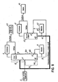
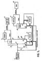
- first 10 and second 20 fractional distillation columns are serially arranged.
- the first column 10 is schematically divided into top 12 and bottom 16 portions, with a feed or entry port 17 and an exit port 18.
- the exact location of the feed port 17 is determined by optimal design, as known to one skilled in the art, and is not necessarily the exact midpoint of the column.
- the feed port 17 is referred to as located at a nominal middle of the column 10.
- the bottom 16 portion is further schematically divided into upper bottom 16a, mid-bottom 16b, and lower bottom 16c portions.
- the specific number of stages constituting the top 12 and bottom 16 portions depend upon the specific column design and the application, as known to one skilled in the art. Examples of these parameters include the feedstock composition, the reflux rate, etc.
- the second column 20 is arranged so that effluent from the first column 10 enters the second column 20 at entry port 27.
- the bottoms product of the second column exits at exit port 28.
- the first column 10 has a condenser 11 overhead and a reboiler 13 at the bottom.
- the second column 20 also has a condenser 21 overhead and a reboiler 23 at the bottom. Fluid from exit port 18 of the first column 10 may be pumped directly to entry port 27 of the second column 20. Alternatively, fluid from exit port 18 of the first column 10 may pass through reboiler 23 and then enter the second column 20. Fluid from the exit port 28 of the second column 20 is repumped (pumparound fluid) into the feed port 17 of first column 10.
- all of the incoming acetic acid in the DMAc-water feedstock 8 is purged using a two column arrangement via a DMAc and acetic acid bottoms pumparound and using operating conditions to render the upper bottom 16a portion of the first column 10 wet. More specifically, and with reference to FIG. 1 , a mixture of aqueous DMAc to be purified is introduced as a feedstock 8 into the first distillation column 10. The temperature of column 10 is controlled such that a temperature in the upper bottom 16a portion indicates this section of the column is substantially wet, while the lower bottom 16c portion of the first column 10 has a higher temperature and remains substantially dry.
- the temperature profile required to effect separation is described as a percentage of the total temperature difference of the temperature of the bottom of the column minus the temperature of the top of the column. Less than about 15% of the total temperature difference in the column occurs in the top portion 12 of the first column 10, less than about 15% of the total temperature difference in the column occurs in the upper bottom 16a portion, and greater than about 70% of the total temperature difference in the column occurs in the mid 16b and lower 16c bottom portions.
- the exact temperatures, in contrast to the percentage temperature difference, is dependant upon the operating pressure of the first column 10.
- the temperature is controlled by adjusting the heat input to the first column reboiler 13, or adjusting the reflux flow rate of distillate on the first column 10.
- the resulting temperature profile generates a temperature plateau below the feed stage temperature to render the upper bottom portion of the column substantially wet.
- the wet upper bottom 16a portion is below the feed port 17, and causes a portion of the acetic acid to be stripped overhead to the distillate product 25 of the first column 10.
- the bottoms product 30 of the first column 10 containing dry DMAc and acetic acid contaminant, is re-fed into the first column 10 through entry port 15 as part of the reboiler 13 arrangement.
- the bottom product 30 at the first column is also fed into the second column 20 through entry port 27.
- Pure DMAc is the distilled product 40 of the second column 20.
- the bottoms product 45 of the second column 20. containing dry DMAc and acetic acid, is returned to the feed port 17 of the first column 10.
- the bottoms pumparound stream 45 flows through the wet upper bottom 16a portion, which again causes a portion of the acetic acid to be stripped overhead in the first column 10.
- a first component is a low boiling compound and is present in a substantial portion in a feed stock, that is, at a concentration of at least about 25%;
- a second component is a high boiling compound relative to the first component and is present in a substantial portion in the feed stock, that is, at a concentration of at least about 5%;
- a third component is present in a minor portion in the feed stock, that is, at a concentration of at most about 5%, and forms a high boiling azeotrope with the second component; and
- the first component can cancel, control, or mitigate the two component azeotrope.
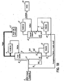
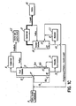
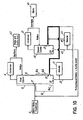
- the first column condenser can be total, for removal of the liquid product FIG. 1A , or partial, for removal of the vapor product FIG. 1B .
- the second column condenser can be total, for removal of the liquid product FIG. 1C , or partial for removal of the vapor product FIG. 1D .
- the bottoms product from the first column can be removed as a liquid FIG. 1E , as a liquid/vapor mix using a common reboiler FIG. 1F , or as a side draw vapor FIG. 1G .
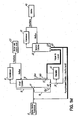
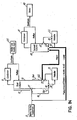
- the bottoms pumparound stream may be returned to the first column into the feed port FIG.
- the bottoms pumparound stream may be obtained from the second column FIG. 1K , or from the first column with the second column bottoms pumparound stream returned to the first column FIG. 1L .
- the bottoms pumparound stream may be obtained while eliminating the reboiler on the second column by using a reboiler common to the first and second columns FIG. 1M , by a side vapor draw to feed the second column to a pumparound stream FIG. 1N , by a side vapor draw to feed the second column to the first column FIG. 1O , or by a common kettle reboiler FIG. 1P .
- a temperature profile to render the upper bottom 16a portion of first column 10 wet, using a twenty-six stage, including the reboiler and condenser, continuous distillation process is shown in the following table.
- the first column 10 is operated with a top pressure of 103 mm Hg, a bottom pressure of 153 mm Hg, and a pressure drop of 50 mm Hg.
- the specific temperatures shown in the following table are, however, a function of the pressure at which the first column is operated, and these specific temperatures or pressures are not required. Thus, any temperature and/or pressure which renders the lower bottom portion of the column substantially dry may be used.
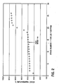
- the temperature profile graphed in FIG. 2 illustrates the percentage temperature differences in various portions of the column.
- This graph has a characteristic shape, where there is only a moderate change (i.e., a temperature plateau) in temperatures in the upper bottom 16a portion (stages 15-17 in this example) of the column 10.
- This characteristic shape occurs regardless of the operating pressure of the column, and is defined in terms of the total temperature difference between the top vapor temperature prior to condensing, and the bottom liquid temperature.
- This temperature profile produces a wet upper bottom 16a portion to the feed port 17, which results in stripping the acetic acid overhead.
- the first column 10 greater than about 70% of the temperature difference occurs in the upper bottom 16a and mid bottom 16b portions (stages 15-20 in this example), less than about 15%.of the temperature difference occurs in the lower bottom 16c portion, and less than 15% of the temperature difference occurs in the top portion 12 (stages 2-13 in this example). These conditions result in the lower bottom 16c portion of the first column 10 remaining substantially dry, while the upper bottom 16a portion of the first column 10 remains substantially wet. Under these conditions, the acetic acid contaminant is partitioned between the overhead stream 25 and the bottom stream 30 of the first column 10.
- the effluent 30 from the bottom portion 16c of the first column 10 and/or second feed column 45 is recycled back into the feed port 17 of the first column 10 in a pumparound loop. This allows substantially all of the acetic acid to locate in the overhead water 25 of the first column 10.
- the material may be received in the second column 20 as either liquid or side-draw vapor from the first column. Any acetic acid is present at less than azeotropic concentration, and thus does not negatively affect separation of the DMAc as a pure component 40 and the operation of the second column 20.
- the method may be used to recover desired lower boiling point products from higher boiling point contaminants by recovering products from the first column distillate.
Landscapes
- Chemical & Material Sciences (AREA)
- Organic Chemistry (AREA)
- Chemical Kinetics & Catalysis (AREA)
- Organic Low-Molecular-Weight Compounds And Preparation Thereof (AREA)
- Vaporization, Distillation, Condensation, Sublimation, And Cold Traps (AREA)
- Solid-Sorbent Or Filter-Aiding Compositions (AREA)
- Pyrrole Compounds (AREA)
- Detergent Compositions (AREA)
Claims (22)
- Verfahren zum Abtrennen von DMAc aus einer Lösung von DMAc in Wasser, und wobei die Lösung DMAc in einer Konzentration von mindestens 5%, Wasser in einer Konzentration von mindestens 25% und Essigsäure in einer Konzentration von höchstens 5% enthält, umfassend(a) Zuführen der Lösung zu einer ersten Destillationssäule, wobei die Säule eine Einspeiseöffnung und eine Eintrittsöffnung aufweist und einen Topabschnitt und einen Bodenabschnitt aufweist, der Bodenabschnitt einen oberen, einen mittleren und einen unteren Bodenabschnitt aufweist, bei einer Temperatur, welche ausreichend ist um den unteren Bodenabschnitt der Säule im Wesentlichen frei von Wasser und den oberen Bodenabschnitt der Säule reich an Wasser zu machen, und um die Essigsäure zwischen einem Wasserkopfstrom und einem Bodenstrom der ersten Säule aufzuteilen,(b) Zuführen des Bodenstroms der ersten Säule zu einer Einlassöffnung einer zweiten Destillationssäule um das gereinigte DMAc in einen Kopfstrom und ein Gemisch von DMAc und Essigsäure in einen Bodenstrom aufzuteilen, und(c) Aufteilen eines zusätzlichen Teils der Essigsäure aus dem Gemisch von DMAc und Essigsäure in den Kopfstrom der ersten Säule.
- Verfahren nach Anspruch 1, des Weiteren umfassend, das gereinigte DMAc aus dem Kopfstrom der zweiten Säule zu gewinnen.
- Verfahren nach Anspruch 1, wobei das Temperaturprofil der ersten Säule dazu führt, dass weniger als 15% der gesamten Temperaturdifferenz in der ersten Säule im Topabschnitt auftritt, weniger als 15% der gesamten Temperaturdifferenz in der ersten Säule im oberen Bodenabschnitt auftritt, und mehr als 70% der gesamten Temperaturdifferenz in der ersten Säule im mittleren und unteren Bodenabschnitt auftritt.
- Verfahren nach Anspruch 1, wobei der Bodenstrom von der zweiten Säule der ersten Säule als ein Umlaufstrom zugeführt wird.
- Verfahren nach Anspruch 4, wobei der Bodenstrom der ersten Säule der zweiten Säule als eine Flüssigeinspeisung zugeführt wird.
- Verfahren nach Anspruch 4, wobeider Bodenstrom der ersten Säule der zweiten Säule als ein seitlich abgezogener Dampf zugeführt wird.
- Verfahren nach Anspruch 4, wobei der ersten Säule der Bodenumlaufstrom an der Einspeiseöffnung zugeführt wird.
- Verfahren nach Anspruch 4, wobei der ersten Säule der Bodenumlaufstrom an einer Eintrittsöffnung oberhalb der Einspeiseöffnung zugeführt wird.
- Verfahren nach Anspruch 4, wobei der ersten Säule der Bodenumlaufstrom an einer Eintrittsöffnung im oberen Bodenabschnitt zugeführt wird.
- Verfahren nach Anspruch 1, wobei der Bodenstrom der zweiten Säule Essigsäure in einer Konzentration enthält, welche geringer ist als eine azeotrope Konzentration.
- Verfahren nach Anspruch 3, wobei die Temperatur eine Funktion eines Drucks ist, bei dem die erste Säule betrieben wird.
- Verfahren nach Anspruch 1, wobei die in den Kopfstrom der ersten Säule aufgeteilte Essigsäure als eine Flüssigkeit gewonnen wird.
- Verfahren nach Anspruch 1, wobei die in den Kopfstrom der ersten Säule aufgeteilte Essigsäure als ein Dampf gewonnen wird.
- Verfahren nach Anspruch 2, wobei das DMAc als eine Flüssigkeit aus dem Kopf der zweiten Säule gewonnen wird.
- Verfahren nach Anspruch 2, wobei das DMAc als ein Dampf aus dem Kopf der zweiten Säule gewonnen wird.
- Verfahren nach Anspruch 1, wobei der Bodenstrom der ersten Säule der zweiten Destillationssäule in einem physikalischen Zustand, ausgewählt aus der Gruppe, bestehend aus einer Flüssigkeit, einem Dampf und einem Flüssigkeit/Dampf-Gemisch, zugeführt wird.
- Verfahren nach Anspruch 1, wobei der zusätzliche Teil an Essigsäure vom Bodenstrom der zweiten Säule zugeführt wird.
- Verfahren nach Anspruch 1, wobei der zusätzliche Teil an Essigsäure aufgeteilt wird durch Zuführen eines Bodenumlaufstroms von der ersten Säule, nachdem ein Bodenstrom von der zweiten Säule zurück zu der ersten Säule geführt worden ist.
- Verfahren nach Anspruch 4, wobei der Bodenumlaufstrom erhalten wird unter Verwendung eines der ersten und der zweiten Säule gemeinsamen Wiederverdampfers.
- Verfahren nach Anspruch 1, des Weiteren umfassend
Zuführen der Lösung zu der Einspeiseöffnung der ersten Destillationssäule,
Zuführen eines Umlaufstroms des undestillierten Bodenprodukts vom Boden der ersten Säule zur Einspeiseöffnung der ersten Säule und zur zweiten Destillationssäule, und
Zuführen des undestillierten Bodenprodukts von der zweiten Säule, welches DMAc und Essigsäure enthält, zu der ersten Säule, um weiter wässrige Essigsäure in den Kopf der ersten Säule aufzuteilen, und DMAcin den Boden der ersten Säule abzutrennen. - Verfahren nach Anspruch 20, des Weiteren umfassend im Wesentlichen reines DMAc als das Destillat von der zweiten Säule zu gewinnen.
- Verfahren nach Anspruch 20, wobei das Temperaturprofil der ersten Säule ein Temperaturprofil unter der Temperatur der Einspeisestufe erzeugt, um den oberen Bodenabschnitt der Säule im Wesentlichen nass zu machen.
Applications Claiming Priority (3)
| Application Number | Priority Date | Filing Date | Title |
|---|---|---|---|
| US186764 | 2002-07-01 | ||
| US10/186,764 US6946060B2 (en) | 2002-07-01 | 2002-07-01 | Purification of N,N-dimethylacetamide |
| PCT/US2003/019405 WO2004002926A2 (en) | 2002-07-01 | 2003-06-18 | Purification of n,n-dimethylacetamide |
Publications (3)
| Publication Number | Publication Date |
|---|---|
| EP1551522A2 EP1551522A2 (de) | 2005-07-13 |
| EP1551522A4 EP1551522A4 (de) | 2005-10-19 |
| EP1551522B1 true EP1551522B1 (de) | 2009-04-01 |
Family
ID=29779931
Family Applications (1)
| Application Number | Title | Priority Date | Filing Date |
|---|---|---|---|
| EP03737193A Expired - Lifetime EP1551522B1 (de) | 2002-07-01 | 2003-06-18 | Reinigung von n,n-dimethylacetamid |
Country Status (12)
| Country | Link |
|---|---|
| US (1) | US6946060B2 (de) |
| EP (1) | EP1551522B1 (de) |
| JP (1) | JP2005531634A (de) |
| CN (1) | CN1326586C (de) |
| AT (1) | ATE427150T1 (de) |
| AU (1) | AU2003238296A1 (de) |
| CA (1) | CA2491342A1 (de) |
| DE (1) | DE60326974D1 (de) |
| ES (1) | ES2322049T3 (de) |
| NO (1) | NO20050520L (de) |
| PT (1) | PT1551522E (de) |
| WO (1) | WO2004002926A2 (de) |
Families Citing this family (25)
| Publication number | Priority date | Publication date | Assignee | Title |
|---|---|---|---|---|
| DE10315214A1 (de) | 2003-04-03 | 2004-10-14 | Basf Ag | Verfahren zur Reinigung von Dimethylacetamid (DMAC) |
| JP3847754B2 (ja) * | 2004-02-03 | 2006-11-22 | 石油資源開発株式会社 | 蒸留塔を用いた水銀除去方法 |
| DE102004030616A1 (de) * | 2004-06-24 | 2006-01-26 | Basf Ag | Verfahren zur Reinigung von Dimethylacetamid (DMAc) |
| EP1712544A1 (de) * | 2005-04-12 | 2006-10-18 | Lonza Ag | Verfahren zur Herstellung von Acetessigsäurearylamiden |
| CN101462977B (zh) * | 2008-07-25 | 2012-07-25 | 烟台泰和新材料股份有限公司 | N,n-二甲基乙酰胺的纯化方法 |
| CN102030672B (zh) * | 2010-12-09 | 2013-10-09 | 南京大学 | 氨纶生产过程中回收超高纯n,n-二甲基乙酰胺溶剂的工艺 |
| RU2509593C1 (ru) * | 2012-10-29 | 2014-03-20 | федеральное государственное бюджетное образовательное учреждение высшего профессионального образования "Национальный исследовательский университет "МЭИ" (ФГБОУ ВПО "НИУ МЭИ") | Способ автоматического управления процессом ректификации и устройство для его осуществления |
| CN102921306B (zh) * | 2012-11-16 | 2015-05-20 | 北京碧水源膜科技有限公司 | 分离膜凝胶浴溶液回收方法及使用回收物制备的分离膜 |
| CN102993039A (zh) * | 2012-12-18 | 2013-03-27 | 常州大学 | 一种回收聚醚砜纺丝废水中二甲基乙酰胺的方法 |
| CN103145577B (zh) * | 2013-02-25 | 2014-08-27 | 天津天中福大科技发展有限公司 | 从制药废液中回收二甲基乙酰胺的方法、设备及热耦合方法 |
| JP6225393B2 (ja) | 2013-07-18 | 2017-11-08 | エルジー・ケム・リミテッド | 蒸留装置 |
| WO2015009116A1 (ko) * | 2013-07-18 | 2015-01-22 | 주식회사 엘지화학 | 증류 장치 |
| RU2558596C2 (ru) * | 2013-11-15 | 2015-08-10 | федеральное государственное бюджетное образовательное учреждение высшего профессионального образования "Национальный исследовательский университет "МЭИ" (ФГБОУ ВПО "НИУ МЭИ") | Способ автоматического управления эффективностью функционирования процесса ректификации |
| CN104016873B (zh) * | 2014-05-28 | 2015-10-28 | 深圳市灿森科技有限公司 | 塑料膜或者聚酰亚胺膜生产中废液的回收方法 |
| CN104926675A (zh) * | 2015-05-18 | 2015-09-23 | 深圳市瑞升华科技股份有限公司 | 低浓度二甲基乙酰胺的回收工艺 |
| EP3554994B1 (de) * | 2016-12-13 | 2020-10-14 | Avantium Knowledge Centre B.V. | Verfahren zur reinigung einer verunreinigten salzsäurezusammensetzung |
| US10287222B1 (en) * | 2017-10-20 | 2019-05-14 | Uop Llc | Process and apparatus for desorbent recovery |
| CN108299190B (zh) * | 2018-03-07 | 2021-03-02 | 福州大学 | 一种分离共沸体系的方法 |
| FR3084668A1 (fr) | 2018-08-02 | 2020-02-07 | Guerbet | Procede de preparation monotope de composes organo-iodes intermediaires a la synthese du ioversol |
| CN109320432A (zh) * | 2018-10-31 | 2019-02-12 | 浙江本优机械有限公司 | 一种用于低浓度二甲基乙酰胺回收提纯的蒸发设备 |
| CN109745723B (zh) * | 2018-12-29 | 2021-07-06 | 恒天纤维集团有限公司 | 一种双塔连续供料精馏系统及控制方法 |
| CN110127789A (zh) * | 2019-05-08 | 2019-08-16 | 河北德瑞化工有限公司 | 一种废水处理系统及其废水处理方法 |
| JP7255042B2 (ja) * | 2019-05-20 | 2023-04-11 | 株式会社レゾナック | N,n-ジメチルカルボン酸アミドの製造方法 |
| DK180599B1 (en) | 2020-01-20 | 2021-10-14 | Blue World Technologies Holding ApS | Apparatus and process for making acid-doped proton exchange membranes |
| CN116903083B (zh) * | 2023-09-07 | 2023-11-21 | 河北乐凯化工工程设计有限公司 | 一种含dmac工业废水的回收处理工艺 |
Family Cites Families (10)
| Publication number | Priority date | Publication date | Assignee | Title |
|---|---|---|---|---|
| US3419478A (en) * | 1966-12-13 | 1968-12-31 | Du Pont | Azeotropic distillation of a n,n-dimethylacetamide-acetic acid mixture using a saturated aliphatic hydrocarbon |
| FR1549711A (de) | 1966-12-15 | 1968-12-13 | ||
| US3687820A (en) * | 1970-11-23 | 1972-08-29 | Du Pont | Process for separating mixtures of n,n-dimethylacetamides and acetic acid by distilling with alternate pressures |
| DE2408011A1 (de) * | 1974-02-20 | 1975-09-04 | Hoechst Ag | Verfahren zur gewinnung von technisch reiner essigsaeure durch extraktivdestillation |
| US3959371A (en) | 1974-10-08 | 1976-05-25 | Custom Organics, Inc. | Process for the purification of N,N-dimethylacetamide |
| DE2631734B2 (de) * | 1976-07-15 | 1978-11-30 | Bayer Ag, 5090 Leverkusen | Verfahren zur Ruckgewinnung von Dimethylac) !amiden |
| NL8103517A (nl) * | 1981-07-24 | 1983-02-16 | Badger Bv | Werkwijze voor het scheiden van carbonzuren van mengsels met niet-zuren door een absorptie-stripbehandeling. |
| US5124004A (en) | 1983-08-22 | 1992-06-23 | Trustees Of Dartmouth College | Distillation process for ethanol |
| DE4109632A1 (de) | 1991-03-23 | 1992-09-24 | Krupp Koppers Gmbh | Verfahren zur abtrennung von aromaten durch extraktivdestillation |
| FR2751558B1 (fr) | 1996-07-26 | 1998-09-18 | Inst Francais Du Petrole | Dispositif de reaction et de distillation et procede d'etherification |
-
2002
- 2002-07-01 US US10/186,764 patent/US6946060B2/en not_active Expired - Lifetime
-
2003
- 2003-06-18 JP JP2004517700A patent/JP2005531634A/ja active Pending
- 2003-06-18 PT PT03737193T patent/PT1551522E/pt unknown
- 2003-06-18 EP EP03737193A patent/EP1551522B1/de not_active Expired - Lifetime
- 2003-06-18 ES ES03737193T patent/ES2322049T3/es not_active Expired - Lifetime
- 2003-06-18 AU AU2003238296A patent/AU2003238296A1/en not_active Abandoned
- 2003-06-18 CN CNB038154617A patent/CN1326586C/zh not_active Expired - Fee Related
- 2003-06-18 AT AT03737193T patent/ATE427150T1/de not_active IP Right Cessation
- 2003-06-18 DE DE60326974T patent/DE60326974D1/de not_active Expired - Fee Related
- 2003-06-18 WO PCT/US2003/019405 patent/WO2004002926A2/en active Application Filing
- 2003-06-18 CA CA002491342A patent/CA2491342A1/en not_active Abandoned
-
2005
- 2005-01-31 NO NO20050520A patent/NO20050520L/no not_active Application Discontinuation
Also Published As
| Publication number | Publication date |
|---|---|
| AU2003238296A1 (en) | 2004-01-19 |
| WO2004002926A3 (en) | 2004-06-03 |
| JP2005531634A (ja) | 2005-10-20 |
| CN1326586C (zh) | 2007-07-18 |
| AU2003238296A8 (en) | 2004-01-19 |
| ES2322049T3 (es) | 2009-06-16 |
| ATE427150T1 (de) | 2009-04-15 |
| US6946060B2 (en) | 2005-09-20 |
| US20040000470A1 (en) | 2004-01-01 |
| WO2004002926A2 (en) | 2004-01-08 |
| EP1551522A4 (de) | 2005-10-19 |
| CN1665574A (zh) | 2005-09-07 |
| PT1551522E (pt) | 2009-07-01 |
| EP1551522A2 (de) | 2005-07-13 |
| NO20050520L (no) | 2005-01-31 |
| CA2491342A1 (en) | 2004-01-08 |
| DE60326974D1 (de) | 2009-05-14 |
Similar Documents
| Publication | Publication Date | Title |
|---|---|---|
| EP1551522B1 (de) | Reinigung von n,n-dimethylacetamid | |
| JP5300182B2 (ja) | m−トルエンジアミン又はm−トルエンジイソシアナートの製造法 | |
| EP1300384B1 (de) | Verfahren zur Rückgewinnung von Acrolein oder Propionaldehyd aus verdünnten wässrigen Strömen | |
| JP2003146948A (ja) | アミン含有混合物を分別する方法 | |
| EP2872473B1 (de) | Verfahren zur herstellung von methylbutinol | |
| JP2003096470A (ja) | 抽出蒸留を用いた芳香族化合物の分離方法およびその方法で用いる複合溶媒 | |
| WO2004085022A8 (en) | Purification of fluid compounds utilizing a distillation-membrane separation process | |
| US6780289B2 (en) | Process for the purification and recovery of acetonitrile | |
| EP1682492A2 (de) | Verfahren zum recycling von acetonitril | |
| EP0002382A2 (de) | Verfahren zur Wiedergewinnung und Reinigung von Acrylsäure | |
| US20060219545A1 (en) | Method for the purification of dimethylacetamide (dmac) | |
| EP1603651B1 (de) | Destillierverfahren zur trennung von hexamethylendiamin von einer mischung aus hexamethylendiamin, -aminocapronitril und tetrahydroazepin | |
| US20120073954A1 (en) | Recovery of acetonitrile from a waste stream | |
| KR20010075276A (ko) | 고순도 모노에틸렌 글리콜의 제조 방법 | |
| US6508917B1 (en) | Method and apparatus for purifying low grade acetonitrile and other constituents from hazardous waste | |
| KR101106538B1 (ko) | 디메틸 카보네이트의 분리 방법 | |
| KR20050016671A (ko) | 엔,엔-디메틸아세트아미드의 정제 | |
| EP2234951B1 (de) | Aufreinigung von phenol | |
| EP1129059B1 (de) | Reinigung von allylalkohol | |
| US4213832A (en) | Distillation for separating dialkylketones from lower chlorohydrocarbons | |
| TW202138341A (zh) | 回收己二腈的方法 | |
| GB2322856A (en) | Purification of Acetonitrile | |
| JPS5998028A (ja) | アニソ−ルの分離方法 | |
| JPH09301914A (ja) | アセトンの精製方法 |
Legal Events
| Date | Code | Title | Description |
|---|---|---|---|
| PUAI | Public reference made under article 153(3) epc to a published international application that has entered the european phase |
Free format text: ORIGINAL CODE: 0009012 |
|
| 17P | Request for examination filed |
Effective date: 20050107 |
|
| AK | Designated contracting states |
Kind code of ref document: A2 Designated state(s): AT BE BG CH CY CZ DE DK EE ES FI FR GB GR HU IE IT LI LU MC NL PT RO SE SI SK TR |
|
| AX | Request for extension of the european patent |
Extension state: AL LT LV MK |
|
| A4 | Supplementary search report drawn up and despatched |
Effective date: 20050902 |
|
| DAX | Request for extension of the european patent (deleted) | ||
| 17Q | First examination report despatched |
Effective date: 20060419 |
|
| GRAP | Despatch of communication of intention to grant a patent |
Free format text: ORIGINAL CODE: EPIDOSNIGR1 |
|
| GRAS | Grant fee paid |
Free format text: ORIGINAL CODE: EPIDOSNIGR3 |
|
| GRAA | (expected) grant |
Free format text: ORIGINAL CODE: 0009210 |
|
| AK | Designated contracting states |
Kind code of ref document: B1 Designated state(s): AT BE BG CH CY CZ DE DK EE ES FI FR GB GR HU IE IT LI LU MC NL PT RO SE SI SK TR |
|
| REG | Reference to a national code |
Ref country code: GB Ref legal event code: FG4D |
|
| REG | Reference to a national code |
Ref country code: CH Ref legal event code: NV Representative=s name: E. BLUM & CO. AG PATENT- UND MARKENANWAELTE VSP Ref country code: CH Ref legal event code: EP |
|
| REG | Reference to a national code |
Ref country code: IE Ref legal event code: FG4D |
|
| REF | Corresponds to: |
Ref document number: 60326974 Country of ref document: DE Date of ref document: 20090514 Kind code of ref document: P |
|
| REG | Reference to a national code |
Ref country code: ES Ref legal event code: FG2A Ref document number: 2322049 Country of ref document: ES Kind code of ref document: T3 |
|
| REG | Reference to a national code |
Ref country code: PT Ref legal event code: SC4A Free format text: AVAILABILITY OF NATIONAL TRANSLATION Effective date: 20090625 |
|
| PG25 | Lapsed in a contracting state [announced via postgrant information from national office to epo] |
Ref country code: SI Free format text: LAPSE BECAUSE OF FAILURE TO SUBMIT A TRANSLATION OF THE DESCRIPTION OR TO PAY THE FEE WITHIN THE PRESCRIBED TIME-LIMIT Effective date: 20090401 |
|
| PGFP | Annual fee paid to national office [announced via postgrant information from national office to epo] |
Ref country code: ES Payment date: 20090626 Year of fee payment: 7 Ref country code: IE Payment date: 20090626 Year of fee payment: 7 |
|
| PGFP | Annual fee paid to national office [announced via postgrant information from national office to epo] |
Ref country code: FR Payment date: 20090617 Year of fee payment: 7 Ref country code: IT Payment date: 20090625 Year of fee payment: 7 |
|
| NLV1 | Nl: lapsed or annulled due to failure to fulfill the requirements of art. 29p and 29m of the patents act | ||
| PG25 | Lapsed in a contracting state [announced via postgrant information from national office to epo] |
Ref country code: FI Free format text: LAPSE BECAUSE OF FAILURE TO SUBMIT A TRANSLATION OF THE DESCRIPTION OR TO PAY THE FEE WITHIN THE PRESCRIBED TIME-LIMIT Effective date: 20090401 Ref country code: EE Free format text: LAPSE BECAUSE OF FAILURE TO SUBMIT A TRANSLATION OF THE DESCRIPTION OR TO PAY THE FEE WITHIN THE PRESCRIBED TIME-LIMIT Effective date: 20090401 Ref country code: AT Free format text: LAPSE BECAUSE OF FAILURE TO SUBMIT A TRANSLATION OF THE DESCRIPTION OR TO PAY THE FEE WITHIN THE PRESCRIBED TIME-LIMIT Effective date: 20090401 |
|
| PGFP | Annual fee paid to national office [announced via postgrant information from national office to epo] |
Ref country code: CH Payment date: 20090625 Year of fee payment: 7 |
|
| PG25 | Lapsed in a contracting state [announced via postgrant information from national office to epo] |
Ref country code: SE Free format text: LAPSE BECAUSE OF FAILURE TO SUBMIT A TRANSLATION OF THE DESCRIPTION OR TO PAY THE FEE WITHIN THE PRESCRIBED TIME-LIMIT Effective date: 20090701 Ref country code: NL Free format text: LAPSE BECAUSE OF FAILURE TO SUBMIT A TRANSLATION OF THE DESCRIPTION OR TO PAY THE FEE WITHIN THE PRESCRIBED TIME-LIMIT Effective date: 20090401 |
|
| PGFP | Annual fee paid to national office [announced via postgrant information from national office to epo] |
Ref country code: CZ Payment date: 20090608 Year of fee payment: 7 Ref country code: DE Payment date: 20090629 Year of fee payment: 7 Ref country code: GB Payment date: 20090625 Year of fee payment: 7 Ref country code: PT Payment date: 20090716 Year of fee payment: 7 |
|
| PG25 | Lapsed in a contracting state [announced via postgrant information from national office to epo] |
Ref country code: MC Free format text: LAPSE BECAUSE OF NON-PAYMENT OF DUE FEES Effective date: 20090630 Ref country code: DK Free format text: LAPSE BECAUSE OF FAILURE TO SUBMIT A TRANSLATION OF THE DESCRIPTION OR TO PAY THE FEE WITHIN THE PRESCRIBED TIME-LIMIT Effective date: 20090401 Ref country code: RO Free format text: LAPSE BECAUSE OF FAILURE TO SUBMIT A TRANSLATION OF THE DESCRIPTION OR TO PAY THE FEE WITHIN THE PRESCRIBED TIME-LIMIT Effective date: 20090401 |
|
| PLBE | No opposition filed within time limit |
Free format text: ORIGINAL CODE: 0009261 |
|
| STAA | Information on the status of an ep patent application or granted ep patent |
Free format text: STATUS: NO OPPOSITION FILED WITHIN TIME LIMIT |
|
| PG25 | Lapsed in a contracting state [announced via postgrant information from national office to epo] |
Ref country code: SK Free format text: LAPSE BECAUSE OF FAILURE TO SUBMIT A TRANSLATION OF THE DESCRIPTION OR TO PAY THE FEE WITHIN THE PRESCRIBED TIME-LIMIT Effective date: 20090401 Ref country code: BE Free format text: LAPSE BECAUSE OF FAILURE TO SUBMIT A TRANSLATION OF THE DESCRIPTION OR TO PAY THE FEE WITHIN THE PRESCRIBED TIME-LIMIT Effective date: 20090401 |
|
| 26N | No opposition filed |
Effective date: 20100105 |
|
| PG25 | Lapsed in a contracting state [announced via postgrant information from national office to epo] |
Ref country code: BG Free format text: LAPSE BECAUSE OF FAILURE TO SUBMIT A TRANSLATION OF THE DESCRIPTION OR TO PAY THE FEE WITHIN THE PRESCRIBED TIME-LIMIT Effective date: 20090701 |
|
| PG25 | Lapsed in a contracting state [announced via postgrant information from national office to epo] |
Ref country code: GR Free format text: LAPSE BECAUSE OF FAILURE TO SUBMIT A TRANSLATION OF THE DESCRIPTION OR TO PAY THE FEE WITHIN THE PRESCRIBED TIME-LIMIT Effective date: 20090702 |
|
| REG | Reference to a national code |
Ref country code: CH Ref legal event code: PL |
|
| GBPC | Gb: european patent ceased through non-payment of renewal fee |
Effective date: 20100618 |
|
| PG25 | Lapsed in a contracting state [announced via postgrant information from national office to epo] |
Ref country code: CZ Free format text: LAPSE BECAUSE OF NON-PAYMENT OF DUE FEES Effective date: 20100618 |
|
| REG | Reference to a national code |
Ref country code: FR Ref legal event code: ST Effective date: 20110228 |
|
| PG25 | Lapsed in a contracting state [announced via postgrant information from national office to epo] |
Ref country code: IT Free format text: LAPSE BECAUSE OF NON-PAYMENT OF DUE FEES Effective date: 20100618 |
|
| PG25 | Lapsed in a contracting state [announced via postgrant information from national office to epo] |
Ref country code: CH Free format text: LAPSE BECAUSE OF NON-PAYMENT OF DUE FEES Effective date: 20100630 Ref country code: DE Free format text: LAPSE BECAUSE OF NON-PAYMENT OF DUE FEES Effective date: 20110101 Ref country code: IE Free format text: LAPSE BECAUSE OF NON-PAYMENT OF DUE FEES Effective date: 20100618 Ref country code: LU Free format text: LAPSE BECAUSE OF NON-PAYMENT OF DUE FEES Effective date: 20090618 Ref country code: LI Free format text: LAPSE BECAUSE OF NON-PAYMENT OF DUE FEES Effective date: 20100630 |
|
| PG25 | Lapsed in a contracting state [announced via postgrant information from national office to epo] |
Ref country code: FR Free format text: LAPSE BECAUSE OF NON-PAYMENT OF DUE FEES Effective date: 20100630 |
|
| PG25 | Lapsed in a contracting state [announced via postgrant information from national office to epo] |
Ref country code: HU Free format text: LAPSE BECAUSE OF FAILURE TO SUBMIT A TRANSLATION OF THE DESCRIPTION OR TO PAY THE FEE WITHIN THE PRESCRIBED TIME-LIMIT Effective date: 20091002 |
|
| REG | Reference to a national code |
Ref country code: ES Ref legal event code: FD2A Effective date: 20110715 |
|
| PG25 | Lapsed in a contracting state [announced via postgrant information from national office to epo] |
Ref country code: ES Free format text: LAPSE BECAUSE OF NON-PAYMENT OF DUE FEES Effective date: 20110705 Ref country code: GB Free format text: LAPSE BECAUSE OF NON-PAYMENT OF DUE FEES Effective date: 20100618 |
|
| PG25 | Lapsed in a contracting state [announced via postgrant information from national office to epo] |
Ref country code: TR Free format text: LAPSE BECAUSE OF FAILURE TO SUBMIT A TRANSLATION OF THE DESCRIPTION OR TO PAY THE FEE WITHIN THE PRESCRIBED TIME-LIMIT Effective date: 20090401 |
|
| PG25 | Lapsed in a contracting state [announced via postgrant information from national office to epo] |
Ref country code: ES Free format text: LAPSE BECAUSE OF NON-PAYMENT OF DUE FEES Effective date: 20100619 Ref country code: CY Free format text: LAPSE BECAUSE OF FAILURE TO SUBMIT A TRANSLATION OF THE DESCRIPTION OR TO PAY THE FEE WITHIN THE PRESCRIBED TIME-LIMIT Effective date: 20090401 |
|
| REG | Reference to a national code |
Ref country code: PT Ref legal event code: MM4A Free format text: LAPSE DUE TO NON-PAYMENT OF FEES Effective date: 20110321 |
|
| PG25 | Lapsed in a contracting state [announced via postgrant information from national office to epo] |
Ref country code: PT Free format text: LAPSE BECAUSE OF NON-PAYMENT OF DUE FEES Effective date: 20120306 |