EP1550738A1 - Vorrichtung und Verfahren zur Abscheidung von atomaren Schichten - Google Patents
Vorrichtung und Verfahren zur Abscheidung von atomaren Schichten Download PDFInfo
- Publication number
- EP1550738A1 EP1550738A1 EP04257924A EP04257924A EP1550738A1 EP 1550738 A1 EP1550738 A1 EP 1550738A1 EP 04257924 A EP04257924 A EP 04257924A EP 04257924 A EP04257924 A EP 04257924A EP 1550738 A1 EP1550738 A1 EP 1550738A1
- Authority
- EP
- European Patent Office
- Prior art keywords
- chamber
- precursor gas
- valve means
- gas
- inlet
- Prior art date
- Legal status (The legal status is an assumption and is not a legal conclusion. Google has not performed a legal analysis and makes no representation as to the accuracy of the status listed.)
- Withdrawn
Links
Images


Classifications
-
- C—CHEMISTRY; METALLURGY
- C23—COATING METALLIC MATERIAL; COATING MATERIAL WITH METALLIC MATERIAL; CHEMICAL SURFACE TREATMENT; DIFFUSION TREATMENT OF METALLIC MATERIAL; COATING BY VACUUM EVAPORATION, BY SPUTTERING, BY ION IMPLANTATION OR BY CHEMICAL VAPOUR DEPOSITION, IN GENERAL; INHIBITING CORROSION OF METALLIC MATERIAL OR INCRUSTATION IN GENERAL
- C23C—COATING METALLIC MATERIAL; COATING MATERIAL WITH METALLIC MATERIAL; SURFACE TREATMENT OF METALLIC MATERIAL BY DIFFUSION INTO THE SURFACE, BY CHEMICAL CONVERSION OR SUBSTITUTION; COATING BY VACUUM EVAPORATION, BY SPUTTERING, BY ION IMPLANTATION OR BY CHEMICAL VAPOUR DEPOSITION, IN GENERAL
- C23C16/00—Chemical coating by decomposition of gaseous compounds, without leaving reaction products of surface material in the coating, i.e. chemical vapour deposition [CVD] processes
- C23C16/44—Chemical coating by decomposition of gaseous compounds, without leaving reaction products of surface material in the coating, i.e. chemical vapour deposition [CVD] processes characterised by the method of coating
- C23C16/455—Chemical coating by decomposition of gaseous compounds, without leaving reaction products of surface material in the coating, i.e. chemical vapour deposition [CVD] processes characterised by the method of coating characterised by the method used for introducing gases into reaction chamber or for modifying gas flows in reaction chamber
- C23C16/45523—Pulsed gas flow or change of composition over time
- C23C16/45525—Atomic layer deposition [ALD]
- C23C16/45544—Atomic layer deposition [ALD] characterized by the apparatus
-
- H—ELECTRICITY
- H10—SEMICONDUCTOR DEVICES; ELECTRIC SOLID-STATE DEVICES NOT OTHERWISE PROVIDED FOR
- H10P—GENERIC PROCESSES OR APPARATUS FOR THE MANUFACTURE OR TREATMENT OF DEVICES COVERED BY CLASS H10
- H10P14/00—Formation of materials, e.g. in the shape of layers or pillars
- H10P14/20—Formation of materials, e.g. in the shape of layers or pillars of semiconductor materials
-
- C—CHEMISTRY; METALLURGY
- C23—COATING METALLIC MATERIAL; COATING MATERIAL WITH METALLIC MATERIAL; CHEMICAL SURFACE TREATMENT; DIFFUSION TREATMENT OF METALLIC MATERIAL; COATING BY VACUUM EVAPORATION, BY SPUTTERING, BY ION IMPLANTATION OR BY CHEMICAL VAPOUR DEPOSITION, IN GENERAL; INHIBITING CORROSION OF METALLIC MATERIAL OR INCRUSTATION IN GENERAL
- C23C—COATING METALLIC MATERIAL; COATING MATERIAL WITH METALLIC MATERIAL; SURFACE TREATMENT OF METALLIC MATERIAL BY DIFFUSION INTO THE SURFACE, BY CHEMICAL CONVERSION OR SUBSTITUTION; COATING BY VACUUM EVAPORATION, BY SPUTTERING, BY ION IMPLANTATION OR BY CHEMICAL VAPOUR DEPOSITION, IN GENERAL
- C23C16/00—Chemical coating by decomposition of gaseous compounds, without leaving reaction products of surface material in the coating, i.e. chemical vapour deposition [CVD] processes
- C23C16/44—Chemical coating by decomposition of gaseous compounds, without leaving reaction products of surface material in the coating, i.e. chemical vapour deposition [CVD] processes characterised by the method of coating
- C23C16/455—Chemical coating by decomposition of gaseous compounds, without leaving reaction products of surface material in the coating, i.e. chemical vapour deposition [CVD] processes characterised by the method of coating characterised by the method used for introducing gases into reaction chamber or for modifying gas flows in reaction chamber
- C23C16/45587—Mechanical means for changing the gas flow
- C23C16/45589—Movable means, e.g. fans
-
- C—CHEMISTRY; METALLURGY
- C23—COATING METALLIC MATERIAL; COATING MATERIAL WITH METALLIC MATERIAL; CHEMICAL SURFACE TREATMENT; DIFFUSION TREATMENT OF METALLIC MATERIAL; COATING BY VACUUM EVAPORATION, BY SPUTTERING, BY ION IMPLANTATION OR BY CHEMICAL VAPOUR DEPOSITION, IN GENERAL; INHIBITING CORROSION OF METALLIC MATERIAL OR INCRUSTATION IN GENERAL
- C23C—COATING METALLIC MATERIAL; COATING MATERIAL WITH METALLIC MATERIAL; SURFACE TREATMENT OF METALLIC MATERIAL BY DIFFUSION INTO THE SURFACE, BY CHEMICAL CONVERSION OR SUBSTITUTION; COATING BY VACUUM EVAPORATION, BY SPUTTERING, BY ION IMPLANTATION OR BY CHEMICAL VAPOUR DEPOSITION, IN GENERAL
- C23C16/00—Chemical coating by decomposition of gaseous compounds, without leaving reaction products of surface material in the coating, i.e. chemical vapour deposition [CVD] processes
- C23C16/44—Chemical coating by decomposition of gaseous compounds, without leaving reaction products of surface material in the coating, i.e. chemical vapour deposition [CVD] processes characterised by the method of coating
- C23C16/458—Chemical coating by decomposition of gaseous compounds, without leaving reaction products of surface material in the coating, i.e. chemical vapour deposition [CVD] processes characterised by the method of coating characterised by the method used for supporting substrates in the reaction chamber
- C23C16/4582—Rigid and flat substrates, e.g. plates or discs
- C23C16/4583—Rigid and flat substrates, e.g. plates or discs the substrate being supported substantially horizontally
- C23C16/4586—Elements in the interior of the support, e.g. electrodes, heating or cooling devices
Definitions
- This invention is directed to atomic layer deposition. More particularly this invention provides an apparatus and process in which precursor gases including the species used to form monatomic layers can be quickly alternated so as to allow the atomic layer deposition process to be conducted with fast cycle time.
- Atomic layer deposition is a method of depositing very thin films onto a surface. Individual precursor gases are pulsed onto the surface, typically a wafer, in a sequential manner without mixing the precursors in the gas phase. Each precursor gas reacts with the surface to form an atomic layer in a way such that only one layer at a time can be deposited onto the surface.
- inert gases such as argon and nitrogen are used as purge gases between application of different precursor gases.
- inert gases such as argon and nitrogen are commonly used precursors.
- the present invention provides an atomic layer deposition arrangement comprising a process chamber including an inlet for receiving precursor gases and at least one outlet coupled through an outlet line to an exhaust pump, first precursor gas valve means coupled to the inlet for receiving a first precursor gas, second precursor gas valve means coupled to the inlet for receiving a second precursor gas, a first bypass conduit coupled to said first precursor gas valve means, and a second bypass conduit coupled to said second precursor gas valve means, wherein the first bypass conduit and the second bypass conduit are isolated from the outlet line.
- a preferred embodiment provides an atomic layer deposition arrangement comprising a process reactor chamber including an inlet for receiving precursor gases and at least one outlet coupled through an outlet line to an exhaust pump, a first precursor gas valve which receives a first precursor gas and second precursor gas valve which receives a second precursor gas.
- the first precursor gas valve and second precursor gas valve are coupled to the inlet of the process reactor chamber.
- a first bypass conduit coupled to the first precursor valve and a second bypass conduit coupled to the second precursor valve allows steady flow of the precursor gases in between delivery to the process reactor chamber.
- the first bypass conduit and second bypass conduit are isolated from the outlet line.
- the outlet line coupled to the exhaust pump allows fast evacuation of the process reactor chamber.
- the present invention provides a method for delivering precursor gas to an atomic layer deposition chamber, the method comprising introducing a substrate into a process chamber having a chamber inlet and chamber outlet, reducing pressure in the chamber, flowing a first precursor gas to an inlet of a first gas valve means in a bypass position coupling the first precursor gas to a first bypass conduit, switching the first gas valve means to a chamber delivery position coupling the first precursor gas to the chamber inlet to deliver the first precursor gas to the chamber, switching the first gas valve means to the bypass position, reducing pressure in the chamber, flowing a second precursor gas to an inlet of a second gas valve means in a bypass position coupling the second precursor gas to a second bypass conduit, switching the second gas valve means to a chamber delivery position coupling the second precursor gas to the chamber inlet to deliver the second precursor gas to the chamber, and switching the second gas valve means to the bypass position, wherein the first bypass conduit and the second bypass conduit are isolated from the outlet.
- Another preferred embodiment provides a method for delivering precursor gas to an atomic layer deposition chamber comprising introducing a substrate into a process reactor chamber having a chamber inlet and a chamber outlet, reducing pressure in the chamber, flowing a first precursor gas to an inlet of a bypass position of a first gas valve, the first gas valve including a chamber delivery position coupled to the chamber inlet, switching the first gas valve to the chamber delivery position to convey the first precursor gas from the gas valve to the chamber inlet, switching the first gas valve to the inlet of the bypass position of the first gas valve, reducing pressure in the chamber, flowing a second precursor gas to the inlet of a bypass position of a second gas valve, the second gas valve including a chamber delivery position coupled to the chamber inlet, switching the second gas valve to a chamber delivery position to convey the second precursor gas from the second gas valve to the chamber inlet, and switching the second gas valve to the inlet of the bypass position of the second gas valve wherein the second precursor gas is conveyed to the chamber inlet without previously purging the chamber with a pur
- the present invention also provides a method for delivering precursor gas to an atomic layer deposition chamber, the method comprising placing a substrate onto a substrate holding device in a process reactor chamber having a chamber inlet and chamber outlet, isolating the chamber by closing a gate valve, reducing pressure in the chamber by moving the substrate holding device upward in a longitudinal direction to provide a high conductance connection between the chamber and the vacuum pump, isolating the chamber from the vacuum pump by moving the substrate holding device downward in a longitudinal direction to provide a minimum conductance connection between the chamber and a vacuum pump, flowing a first precursor gas to an inlet of a bypass position of a first gas valve, the first gas valve including a chamber delivery position coupled to the chamber inlet, switching said first gas valve to the chamber delivery position to convey the first precursor gas from the gas valve to the chamber inlet, switching said first gas valve to the inlet of the bypass position of the first gas valve, reducing pressure in the chamber by moving the position of the substrate holding device upward in a longitudinal direction to provide a high conductance connection between the chamber
- the present invention further provides method for delivering precursor gas to an atomic layer deposition chamber, the method comprising placing a substrate onto a substrate holding device in a process reactor chamber having a chamber inlet and chamber outlet, isolating the chamber by closing a gate valve, reducing pressure in the chamber by moving the substrate holding device upward in a longitudinal direction to provide a high conductance connection between the chamber and a vacuum pump, isolating the chamber from the vacuum pump by moving the substrate holding device downward in a longitudinal direction to provide a minimum conductance connection between the chamber and the vacuum pump, flowing a first precursor gas to an inlet of a bypass position of a first gas valve, the first gas valve including a chamber delivery position coupled to the chambers inlet, switching said first gas valve to the chamber delivery position to convey the first precursor gas from the gas valve to the chamber inlet, switching said first gas valve to the inlet of the bypass position of the first gas valve, reducing the pressure in the chamber by moving the substrate holding device upward in a longitudinal direction to provide a high conductance connection between the chamber and a
- the atomic layer deposition system includes a process reactor chamber 10 including an inlet 12 for receiving precursor gases.
- a process reactor chamber outlet 14 is coupled through an outlet line 16 to an exhaust pump 18.
- the exhaust pump may be any suitably sized vacuum pump, such as the EPX 180L Dry Pump available from BOC Edwards.
- a first precursor gas valve 20 receives a first precursor gas A and a second precursor valve 22 receives a second precursor gas B.
- a first bypass conduit 24 is coupled to first precursor valve 20 and a second bypass conduit 26 is coupled to second precursor valve 22. As can be seen from Figure 1, first bypass conduit 24 and second bypass conduit 26 are isolated from outlet line 16.
- two sets of two way valves 45 can be used instead of a three way valve as shown in Figure 2.
- a substrate is introduced into the process reactor chamber 10 through an opening, which is selectively closed through gate valve 30.
- the substrate may be for example, a processed semiconductor wafer, an unprocessed semiconductor wafer or a substrate intended for a flat panel display and/or any other type of substrate.
- a vacuum hold down is applied to the platen 32 by opening vacuum valve 34.
- the exhaust pump 18 is in flow communication with the chamber 10.
- Vacuum valves 34, 35 are arranged in direct communication with the chamber 10 and a vacuum hold down system 40.
- the vacuum hold down system 40 is configured to hold the substrate onto platen 32 during movement of the platen 32.
- Vacuum valve 42 may be in flow communication with the chamber 10 through the sub-chamber 44.
- a plurality of vacuum gauges 36, 38 may be provided to monitor the rate of evacuation of the chamber 10 through the vacuum valves 34, 35 and 42.
- a check valve 46 may be associated with the gas flow path downstream from exhaust valve 48 to prevent back flow of gas while the exhaust valve 48 is open in the event the chamber 10 is under pressurized.
- the vacuum pump 18 is connected to a vent 50.
- FIG. 3 A more detailed view of the platen 32 is shown in Figure 3.
- the platen 32 is attached to a movement mechanism 52 which may be a linear actuator, a hydraulic piston, a pneumatic piston, or any other mechanism suitable for linear motion to the platen 32.
- the platen 32 has at least one through hole 100 formed therein.
- the platen 32 also has a first hollow shaft portion 102 and a second hollow shaft portion 104 in flow communication with the through hole 100 in the platen.
- a port member 106 is inserted into vacuum outlet 40, which is in flow communication with the hollow shaft portion 102.
- the other end of the port member 106 is in flow communication with the vacuum pump 18, shown in Figure 1.
- the structure 122 forming a flow path placing the through hole 100 in flow communication with the vacuum pump 18 forms a vacuum hold down that secures the object to the surface of the platen 32.
- a plurality of raised portions 124 assist in distributing vacuum force to the surface of the platen and thereby aid in securing an object to the platen 32.
- a movement mechanism 52 which may be a linear actuator, a hydraulic piston, a pneumatic piston, or any other mechanism suitable for providing linear motion to the platen 32.
- the movement mechanism 52 is arranged within a support member 110 affixed to the sub-chamber 44.
- the sub-chamber 44 may be fastened to the chamber 10 of Figure 1 via one or more through holes 114 (only one of which is shown). This arrangement allows the platen 32 to be raised and lowered in relation to the sub-chamber 44 and the interior of the chamber 10.
- a steel bellows 116 is also contained within the sub-chamber 44 to cooperate with a radically extending flange portion 118 on the hollow shaft portion 102 to seal the sub-chamber 44 around the hollow shaft portion 104.
- the sub-chamber 44 includes an outlet 14 (e.g., exhaust port) that provides flow communication between the interior of the chamber 10 of Figure 1 and vacuum pump 18.
- the outlet 14 and outlet line 16 define an exhaust flow path that may be connected to both the vacuum pump 18 and the exhaust valve 48, shown in Figure 1, to provide vacuum flow in the exhaust flow path.
- the platen 32 is arranged above the outlet 14 and is movable in the interior of the chamber 10 so as to adjust conductance of the exhaust flow from the interior of the chamber 10 to the exhaust flow path via the outlet 14.
- the platen 32 can be raised and lowered to vary the distance H between a lower surface 126 of the platen and the upper surface 128 of the sub-chamber 44. Varying the distance H controls the rate at which gas is withdrawn from the chamber 10 during placement of the chamber into vacuum condition and varies the conductance between the platen 32 and the sub-chamber 44 through the outlet 14.
- This object receiving mechanism 130 is configured to increase throttling of gas being withdrawn when the object receiving mechanism 130 is in a lowered position and to decrease the throttling when the object receiving mechanism 130 is in a raised positioned. This may prevent damage to the object 28 during the gas evacuation process. In addition, by raising the object receiving mechanism 130, the conductance is increased and by lowering the object receiving mechanism 130, the conductance is decreased.
- the movement mechanism 52 is moved downwards to create minimum conductance to the vacuum pump 18.
- the 3 way valve 20 is then switched to allow flow of vapor/gas species A to the chamber 10 to deposit a monatomic layer onto the substrate. During this process the chamber pressure will rise to around atmospheric pressure.
- the valve 20 is then switched to bypass and the movement mechanism 52 moves upward to allow evacuation of the chamber 10 to remove vapor/gas species A.
- the movement mechanism 52 moves downward to provide the minimum conductance to the vacuum pump and valve 22 is switched to allow flow of vapor/gas species B to the chamber 10 to deposit a monatomic layer onto the substrate.
- the above process is repeated to provide sequential deposition of a plurality of layers of A and B until the desired deposition thickness is achieved.
- Each species/layer can be deposited in a 1-2 second cycle time.
- isolation valve 48 is opened, valve 42 is closed and valve 35 is opened to allow the wafer vacuum hold down to be released.
- the gate valve 30 is then opened to allow the substrate to be removed from the chamber.
- the process chamber 10 may be connected to a conventional vacuum cluster central handler or alternatively connected to an atmospheric robot handling system. This allows atomic layer deposition processes to be integrated to any configuration of wafer processing architecture.
- a purge gas for example, nitrogen or argon
- a purge gas for example, nitrogen or argon
- the purge gas flows through process reactor chamber 10 to the vacuum pump.
- the purge gas is introduced into process reactor chamber 10 at a pressure of 5 standard (std) liters per minute for less than 5 seconds duration, more preferably 1 standard (std) liter per minute for less than 2 seconds duration.
- the purge process is substantially reduced. In this manner, the invention provides for fast cycle times.
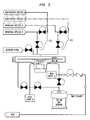
- FIG. 5 An embodiment including a purge gas system wherein the precursor gases are metered using two way valves is shown in Figure 5.
- the two sets of two way valves 210 and 220 control the flow of precursor gas A and precursor gas B.
- an atomic layer deposition process is described in which precursor gases including species used to form monatomic layers are quickly alternated as to allow the atomic layer deposition process to be conducted with fast cycle time.
Landscapes
- Chemical & Material Sciences (AREA)
- General Chemical & Material Sciences (AREA)
- Chemical Kinetics & Catalysis (AREA)
- Engineering & Computer Science (AREA)
- Materials Engineering (AREA)
- Mechanical Engineering (AREA)
- Metallurgy (AREA)
- Organic Chemistry (AREA)
- Chemical Vapour Deposition (AREA)
- Electrodes Of Semiconductors (AREA)
- Formation Of Insulating Films (AREA)
Applications Claiming Priority (2)
| Application Number | Priority Date | Filing Date | Title |
|---|---|---|---|
| US750310 | 2003-12-31 | ||
| US10/750,310 US20050145181A1 (en) | 2003-12-31 | 2003-12-31 | Method and apparatus for high speed atomic layer deposition |
Publications (1)
| Publication Number | Publication Date |
|---|---|
| EP1550738A1 true EP1550738A1 (de) | 2005-07-06 |
Family
ID=34574810
Family Applications (1)
| Application Number | Title | Priority Date | Filing Date |
|---|---|---|---|
| EP04257924A Withdrawn EP1550738A1 (de) | 2003-12-31 | 2004-12-17 | Vorrichtung und Verfahren zur Abscheidung von atomaren Schichten |
Country Status (4)
| Country | Link |
|---|---|
| US (1) | US20050145181A1 (de) |
| EP (1) | EP1550738A1 (de) |
| JP (1) | JP2005232591A (de) |
| KR (1) | KR20050071360A (de) |
Cited By (2)
| Publication number | Priority date | Publication date | Assignee | Title |
|---|---|---|---|---|
| CN110551990A (zh) * | 2018-06-04 | 2019-12-10 | Asm Ip控股有限公司 | 气体分配系统和包括该气体分配系统的反应器系统 |
| TWI900518B (zh) * | 2020-01-23 | 2025-10-11 | 荷蘭商Asm Ip私人控股有限公司 | 穩定壓力之方法 |
Families Citing this family (4)
| Publication number | Priority date | Publication date | Assignee | Title |
|---|---|---|---|---|
| US20040261712A1 (en) * | 2003-04-25 | 2004-12-30 | Daisuke Hayashi | Plasma processing apparatus |
| KR100672829B1 (ko) * | 2005-08-31 | 2007-01-22 | 삼성전자주식회사 | 전하 트랩 절연체의 제조 방법 및 소노스 타입의 비휘발성메모리 장치의 제조방법 |
| KR101288130B1 (ko) | 2011-07-13 | 2013-07-19 | 삼성디스플레이 주식회사 | 기상 증착 장치, 기상 증착 방법 및 유기 발광 표시 장치 제조 방법 |
| FI129502B (en) * | 2019-04-25 | 2022-03-31 | Beneq Oy | Feedstock supply cabinet |
Citations (8)
| Publication number | Priority date | Publication date | Assignee | Title |
|---|---|---|---|---|
| US5241987A (en) * | 1989-04-26 | 1993-09-07 | Tadahiro Ohmi | Process gas supplying apparatus |
| US5250323A (en) * | 1989-10-30 | 1993-10-05 | Kabushiki Kaisha Toshiba | Chemical vapor growth apparatus having an exhaust device including trap |
| EP0651432A1 (de) * | 1993-10-27 | 1995-05-03 | Kiyohara, Masako | Verfahren zum Zuführen von Gasen in eine Reaktions- bzw. Niederschlagskammer |
| US6113698A (en) * | 1997-07-10 | 2000-09-05 | Applied Materials, Inc. | Degassing method and apparatus |
| US20010011526A1 (en) * | 1997-03-03 | 2001-08-09 | Kenneth Doering | Processing chamber for atomic layer deposition processes |
| US20020117222A1 (en) * | 1999-07-01 | 2002-08-29 | Nippon Sanso Corporation | Apparatus and process for supplying gas |
| WO2003033762A1 (en) * | 2001-10-15 | 2003-04-24 | Micron Technology, Inc. | Atomic layer deposition apparatus and process |
| WO2003087429A1 (en) * | 2002-04-06 | 2003-10-23 | Jung Joong Lee | Automatic valve control system in plasma chemical vapor deposition system and chemical vapor deposition system for deposition of nano-scale multilayer film |
Family Cites Families (3)
| Publication number | Priority date | Publication date | Assignee | Title |
|---|---|---|---|---|
| US4657618A (en) * | 1984-10-22 | 1987-04-14 | Texas Instruments Incorporated | Powered load lock electrode/substrate assembly including robot arm, optimized for plasma process uniformity and rate |
| US5324386A (en) * | 1991-03-19 | 1994-06-28 | Fujitsu Limited | Method of growing group II-IV mixed compound semiconductor and an apparatus used therefor |
| JP3854555B2 (ja) * | 2002-08-30 | 2006-12-06 | 東京エレクトロン株式会社 | 薄膜形成装置および薄膜形成方法 |
-
2003
- 2003-12-31 US US10/750,310 patent/US20050145181A1/en not_active Abandoned
-
2004
- 2004-12-17 EP EP04257924A patent/EP1550738A1/de not_active Withdrawn
- 2004-12-28 JP JP2004380906A patent/JP2005232591A/ja active Pending
- 2004-12-31 KR KR1020040117650A patent/KR20050071360A/ko not_active Ceased
Patent Citations (8)
| Publication number | Priority date | Publication date | Assignee | Title |
|---|---|---|---|---|
| US5241987A (en) * | 1989-04-26 | 1993-09-07 | Tadahiro Ohmi | Process gas supplying apparatus |
| US5250323A (en) * | 1989-10-30 | 1993-10-05 | Kabushiki Kaisha Toshiba | Chemical vapor growth apparatus having an exhaust device including trap |
| EP0651432A1 (de) * | 1993-10-27 | 1995-05-03 | Kiyohara, Masako | Verfahren zum Zuführen von Gasen in eine Reaktions- bzw. Niederschlagskammer |
| US20010011526A1 (en) * | 1997-03-03 | 2001-08-09 | Kenneth Doering | Processing chamber for atomic layer deposition processes |
| US6113698A (en) * | 1997-07-10 | 2000-09-05 | Applied Materials, Inc. | Degassing method and apparatus |
| US20020117222A1 (en) * | 1999-07-01 | 2002-08-29 | Nippon Sanso Corporation | Apparatus and process for supplying gas |
| WO2003033762A1 (en) * | 2001-10-15 | 2003-04-24 | Micron Technology, Inc. | Atomic layer deposition apparatus and process |
| WO2003087429A1 (en) * | 2002-04-06 | 2003-10-23 | Jung Joong Lee | Automatic valve control system in plasma chemical vapor deposition system and chemical vapor deposition system for deposition of nano-scale multilayer film |
Cited By (2)
| Publication number | Priority date | Publication date | Assignee | Title |
|---|---|---|---|---|
| CN110551990A (zh) * | 2018-06-04 | 2019-12-10 | Asm Ip控股有限公司 | 气体分配系统和包括该气体分配系统的反应器系统 |
| TWI900518B (zh) * | 2020-01-23 | 2025-10-11 | 荷蘭商Asm Ip私人控股有限公司 | 穩定壓力之方法 |
Also Published As
| Publication number | Publication date |
|---|---|
| US20050145181A1 (en) | 2005-07-07 |
| JP2005232591A (ja) | 2005-09-02 |
| KR20050071360A (ko) | 2005-07-07 |
Similar Documents
| Publication | Publication Date | Title |
|---|---|---|
| JP3078620U (ja) | 薄膜を成長させるための装置 | |
| JP3403181B2 (ja) | 熱処理装置及び熱処理方法 | |
| JP2763222B2 (ja) | 化学気相成長方法ならびにそのための化学気相成長処理システムおよび化学気相成長装置 | |
| CN102046856B (zh) | 用于沉积反应器的方法和装置 | |
| US20040250765A1 (en) | Processing apparatus | |
| US20100022093A1 (en) | Vacuum processing apparatus, method of operating same and storage medium | |
| KR101204640B1 (ko) | 진공 처리 시스템 | |
| KR100674467B1 (ko) | 기판 처리 장치 및 반도체 장치의 제조 방법 | |
| KR20080066531A (ko) | 진공처리장치 및 그 진공처리장치를 사용한 진공처리방법 | |
| KR101210458B1 (ko) | 반도체 장치의 제조 방법 및 기판 처리 장치 | |
| KR102717050B1 (ko) | 가스공급장치, 이를 가지는 기판처리장치, 기판처리시스템 및 기판처리방법 | |
| US8051870B2 (en) | Pressure reduction process device, pressure reduction process method, and pressure regulation valve | |
| EP1550738A1 (de) | Vorrichtung und Verfahren zur Abscheidung von atomaren Schichten | |
| US6701972B2 (en) | Vacuum load lock, system including vacuum load lock, and associated methods | |
| US6908838B2 (en) | Method and device for treating semiconductor substrates | |
| US6086678A (en) | Pressure equalization system for chemical vapor deposition reactors | |
| JP2000232071A (ja) | 基板処理方法および基板処理装置 | |
| JPH0982594A (ja) | 半導体製造装置における室内減圧方法 | |
| JP2006086186A (ja) | 基板処理装置 | |
| JP4748594B2 (ja) | 真空処理装置および真空処理方法 | |
| KR20040079469A (ko) | 소스 가스 공급 장치 | |
| CN120020472A (zh) | 晶圆冷却处理装置、方法及半导体工艺设备 | |
| CN121228203A (zh) | 一种原子层沉积设备及沉积方法 | |
| KR20060099777A (ko) | 반도체 확산 설비의 배기 시스템 | |
| JP2005285922A (ja) | 基板処理装置 |
Legal Events
| Date | Code | Title | Description |
|---|---|---|---|
| PUAI | Public reference made under article 153(3) epc to a published international application that has entered the european phase |
Free format text: ORIGINAL CODE: 0009012 |
|
| AK | Designated contracting states |
Kind code of ref document: A1 Designated state(s): AT BE BG CH CY CZ DE DK EE ES FI FR GB GR HU IE IS IT LI LT LU MC NL PL PT RO SE SI SK TR |
|
| AX | Request for extension of the european patent |
Extension state: AL BA HR LV MK YU |
|
| 17P | Request for examination filed |
Effective date: 20060103 |
|
| AKX | Designation fees paid |
Designated state(s): AT BE BG CH CY CZ DE DK EE ES FI FR GB GR HU IE IS IT LI LT LU MC NL PL PT RO SE SI SK TR |
|
| RAP1 | Party data changed (applicant data changed or rights of an application transferred) |
Owner name: BOC EDWARDS, INC. |
|
| RAP1 | Party data changed (applicant data changed or rights of an application transferred) |
Owner name: EDWARDS VACUUM, INC. |
|
| STAA | Information on the status of an ep patent application or granted ep patent |
Free format text: STATUS: THE APPLICATION IS DEEMED TO BE WITHDRAWN |
|
| 18D | Application deemed to be withdrawn |
Effective date: 20080701 |