EP1550502B1 - Wirbelbettvorrichtung - Google Patents
Wirbelbettvorrichtung Download PDFInfo
- Publication number
- EP1550502B1 EP1550502B1 EP03794072.3A EP03794072A EP1550502B1 EP 1550502 B1 EP1550502 B1 EP 1550502B1 EP 03794072 A EP03794072 A EP 03794072A EP 1550502 B1 EP1550502 B1 EP 1550502B1
- Authority
- EP
- European Patent Office
- Prior art keywords
- processing container
- disintegrator
- fluidized bed
- powder particles
- particles
- Prior art date
- Legal status (The legal status is an assumption and is not a legal conclusion. Google has not performed a legal analysis and makes no representation as to the accuracy of the status listed.)
- Expired - Lifetime
Links
- 239000002245 particle Substances 0.000 claims abstract description 102
- 239000007921 spray Substances 0.000 claims abstract description 51
- 239000000843 powder Substances 0.000 claims abstract description 48
- 239000006185 dispersion Substances 0.000 claims abstract description 13
- 238000005507 spraying Methods 0.000 claims description 5
- 238000000576 coating method Methods 0.000 description 17
- 239000011248 coating agent Substances 0.000 description 16
- 230000000694 effects Effects 0.000 description 13
- 239000010419 fine particle Substances 0.000 description 8
- 238000005469 granulation Methods 0.000 description 8
- 230000003179 granulation Effects 0.000 description 8
- 239000012615 aggregate Substances 0.000 description 7
- 238000001035 drying Methods 0.000 description 6
- 238000005054 agglomeration Methods 0.000 description 5
- 230000002776 aggregation Effects 0.000 description 5
- 230000002093 peripheral effect Effects 0.000 description 5
- 230000001174 ascending effect Effects 0.000 description 3
- 238000010276 construction Methods 0.000 description 3
- 230000003247 decreasing effect Effects 0.000 description 3
- 238000004519 manufacturing process Methods 0.000 description 3
- 239000011230 binding agent Substances 0.000 description 2
- 238000009826 distribution Methods 0.000 description 2
- 239000000463 material Substances 0.000 description 2
- 239000011148 porous material Substances 0.000 description 2
- 238000003756 stirring Methods 0.000 description 2
- 238000005299 abrasion Methods 0.000 description 1
- 239000003905 agrochemical Substances 0.000 description 1
- 230000003466 anti-cipated effect Effects 0.000 description 1
- 238000010009 beating Methods 0.000 description 1
- 230000015572 biosynthetic process Effects 0.000 description 1
- 239000003795 chemical substances by application Substances 0.000 description 1
- 150000001875 compounds Chemical class 0.000 description 1
- 238000009792 diffusion process Methods 0.000 description 1
- 239000003995 emulsifying agent Substances 0.000 description 1
- 238000002474 experimental method Methods 0.000 description 1
- 238000001125 extrusion Methods 0.000 description 1
- 238000001914 filtration Methods 0.000 description 1
- 238000005243 fluidization Methods 0.000 description 1
- 235000013305 food Nutrition 0.000 description 1
- 239000008187 granular material Substances 0.000 description 1
- 238000010438 heat treatment Methods 0.000 description 1
- 239000002184 metal Substances 0.000 description 1
- 238000000034 method Methods 0.000 description 1
- 239000003595 mist Substances 0.000 description 1
- 238000005192 partition Methods 0.000 description 1
- 239000008177 pharmaceutical agent Substances 0.000 description 1
- 239000000825 pharmaceutical preparation Substances 0.000 description 1
- 230000002035 prolonged effect Effects 0.000 description 1
- 238000004080 punching Methods 0.000 description 1
- 230000003252 repetitive effect Effects 0.000 description 1
- 238000005096 rolling process Methods 0.000 description 1
- 238000007789 sealing Methods 0.000 description 1
- 238000010008 shearing Methods 0.000 description 1
- 125000006850 spacer group Chemical group 0.000 description 1
Images





Classifications
-
- B—PERFORMING OPERATIONS; TRANSPORTING
- B01—PHYSICAL OR CHEMICAL PROCESSES OR APPARATUS IN GENERAL
- B01J—CHEMICAL OR PHYSICAL PROCESSES, e.g. CATALYSIS OR COLLOID CHEMISTRY; THEIR RELEVANT APPARATUS
- B01J2/00—Processes or devices for granulating materials, e.g. fertilisers in general; Rendering particulate materials free flowing in general, e.g. making them hydrophobic
- B01J2/006—Coating of the granules without description of the process or the device by which the granules are obtained
-
- B—PERFORMING OPERATIONS; TRANSPORTING
- B01—PHYSICAL OR CHEMICAL PROCESSES OR APPARATUS IN GENERAL
- B01J—CHEMICAL OR PHYSICAL PROCESSES, e.g. CATALYSIS OR COLLOID CHEMISTRY; THEIR RELEVANT APPARATUS
- B01J2/00—Processes or devices for granulating materials, e.g. fertilisers in general; Rendering particulate materials free flowing in general, e.g. making them hydrophobic
- B01J2/16—Processes or devices for granulating materials, e.g. fertilisers in general; Rendering particulate materials free flowing in general, e.g. making them hydrophobic by suspending the powder material in a gas, e.g. in fluidised beds or as a falling curtain
-
- B—PERFORMING OPERATIONS; TRANSPORTING
- B01—PHYSICAL OR CHEMICAL PROCESSES OR APPARATUS IN GENERAL
- B01J—CHEMICAL OR PHYSICAL PROCESSES, e.g. CATALYSIS OR COLLOID CHEMISTRY; THEIR RELEVANT APPARATUS
- B01J8/00—Chemical or physical processes in general, conducted in the presence of fluids and solid particles; Apparatus for such processes
- B01J8/005—Separating solid material from the gas/liquid stream
- B01J8/006—Separating solid material from the gas/liquid stream by filtration
-
- B—PERFORMING OPERATIONS; TRANSPORTING
- B01—PHYSICAL OR CHEMICAL PROCESSES OR APPARATUS IN GENERAL
- B01J—CHEMICAL OR PHYSICAL PROCESSES, e.g. CATALYSIS OR COLLOID CHEMISTRY; THEIR RELEVANT APPARATUS
- B01J8/00—Chemical or physical processes in general, conducted in the presence of fluids and solid particles; Apparatus for such processes
- B01J8/18—Chemical or physical processes in general, conducted in the presence of fluids and solid particles; Apparatus for such processes with fluidised particles
- B01J8/1818—Feeding of the fluidising gas
-
- B—PERFORMING OPERATIONS; TRANSPORTING
- B01—PHYSICAL OR CHEMICAL PROCESSES OR APPARATUS IN GENERAL
- B01J—CHEMICAL OR PHYSICAL PROCESSES, e.g. CATALYSIS OR COLLOID CHEMISTRY; THEIR RELEVANT APPARATUS
- B01J8/00—Chemical or physical processes in general, conducted in the presence of fluids and solid particles; Apparatus for such processes
- B01J8/18—Chemical or physical processes in general, conducted in the presence of fluids and solid particles; Apparatus for such processes with fluidised particles
- B01J8/1845—Chemical or physical processes in general, conducted in the presence of fluids and solid particles; Apparatus for such processes with fluidised particles with particles moving upwards while fluidised
- B01J8/1854—Chemical or physical processes in general, conducted in the presence of fluids and solid particles; Apparatus for such processes with fluidised particles with particles moving upwards while fluidised followed by a downward movement inside the reactor to form a loop
-
- B—PERFORMING OPERATIONS; TRANSPORTING
- B01—PHYSICAL OR CHEMICAL PROCESSES OR APPARATUS IN GENERAL
- B01J—CHEMICAL OR PHYSICAL PROCESSES, e.g. CATALYSIS OR COLLOID CHEMISTRY; THEIR RELEVANT APPARATUS
- B01J8/00—Chemical or physical processes in general, conducted in the presence of fluids and solid particles; Apparatus for such processes
- B01J8/18—Chemical or physical processes in general, conducted in the presence of fluids and solid particles; Apparatus for such processes with fluidised particles
- B01J8/1845—Chemical or physical processes in general, conducted in the presence of fluids and solid particles; Apparatus for such processes with fluidised particles with particles moving upwards while fluidised
- B01J8/1863—Chemical or physical processes in general, conducted in the presence of fluids and solid particles; Apparatus for such processes with fluidised particles with particles moving upwards while fluidised followed by a downward movement outside the reactor and subsequently re-entering it
-
- B—PERFORMING OPERATIONS; TRANSPORTING
- B01—PHYSICAL OR CHEMICAL PROCESSES OR APPARATUS IN GENERAL
- B01J—CHEMICAL OR PHYSICAL PROCESSES, e.g. CATALYSIS OR COLLOID CHEMISTRY; THEIR RELEVANT APPARATUS
- B01J8/00—Chemical or physical processes in general, conducted in the presence of fluids and solid particles; Apparatus for such processes
- B01J8/18—Chemical or physical processes in general, conducted in the presence of fluids and solid particles; Apparatus for such processes with fluidised particles
- B01J8/24—Chemical or physical processes in general, conducted in the presence of fluids and solid particles; Apparatus for such processes with fluidised particles according to "fluidised-bed" technique
- B01J8/38—Chemical or physical processes in general, conducted in the presence of fluids and solid particles; Apparatus for such processes with fluidised particles according to "fluidised-bed" technique with fluidised bed containing a rotatable device or being subject to rotation or to a circulatory movement, i.e. leaving a vessel and subsequently re-entering it
-
- B—PERFORMING OPERATIONS; TRANSPORTING
- B01—PHYSICAL OR CHEMICAL PROCESSES OR APPARATUS IN GENERAL
- B01J—CHEMICAL OR PHYSICAL PROCESSES, e.g. CATALYSIS OR COLLOID CHEMISTRY; THEIR RELEVANT APPARATUS
- B01J8/00—Chemical or physical processes in general, conducted in the presence of fluids and solid particles; Apparatus for such processes
- B01J8/18—Chemical or physical processes in general, conducted in the presence of fluids and solid particles; Apparatus for such processes with fluidised particles
- B01J8/24—Chemical or physical processes in general, conducted in the presence of fluids and solid particles; Apparatus for such processes with fluidised particles according to "fluidised-bed" technique
- B01J8/38—Chemical or physical processes in general, conducted in the presence of fluids and solid particles; Apparatus for such processes with fluidised particles according to "fluidised-bed" technique with fluidised bed containing a rotatable device or being subject to rotation or to a circulatory movement, i.e. leaving a vessel and subsequently re-entering it
- B01J8/382—Chemical or physical processes in general, conducted in the presence of fluids and solid particles; Apparatus for such processes with fluidised particles according to "fluidised-bed" technique with fluidised bed containing a rotatable device or being subject to rotation or to a circulatory movement, i.e. leaving a vessel and subsequently re-entering it with a rotatable device only
-
- B—PERFORMING OPERATIONS; TRANSPORTING
- B01—PHYSICAL OR CHEMICAL PROCESSES OR APPARATUS IN GENERAL
- B01J—CHEMICAL OR PHYSICAL PROCESSES, e.g. CATALYSIS OR COLLOID CHEMISTRY; THEIR RELEVANT APPARATUS
- B01J8/00—Chemical or physical processes in general, conducted in the presence of fluids and solid particles; Apparatus for such processes
- B01J8/18—Chemical or physical processes in general, conducted in the presence of fluids and solid particles; Apparatus for such processes with fluidised particles
- B01J8/24—Chemical or physical processes in general, conducted in the presence of fluids and solid particles; Apparatus for such processes with fluidised particles according to "fluidised-bed" technique
- B01J8/38—Chemical or physical processes in general, conducted in the presence of fluids and solid particles; Apparatus for such processes with fluidised particles according to "fluidised-bed" technique with fluidised bed containing a rotatable device or being subject to rotation or to a circulatory movement, i.e. leaving a vessel and subsequently re-entering it
- B01J8/384—Chemical or physical processes in general, conducted in the presence of fluids and solid particles; Apparatus for such processes with fluidised particles according to "fluidised-bed" technique with fluidised bed containing a rotatable device or being subject to rotation or to a circulatory movement, i.e. leaving a vessel and subsequently re-entering it being subject to a circulatory movement only
- B01J8/386—Chemical or physical processes in general, conducted in the presence of fluids and solid particles; Apparatus for such processes with fluidised particles according to "fluidised-bed" technique with fluidised bed containing a rotatable device or being subject to rotation or to a circulatory movement, i.e. leaving a vessel and subsequently re-entering it being subject to a circulatory movement only internally, i.e. the particles rotate within the vessel
Definitions
- the present invention relates to a fluidized bed apparatus used in the production of fine particles, granules, etc. of pharmaceutical preparations, agricultural chemicals, food products, etc., and more specifically to a fluidized bed apparatus suitable for coating processing on particles of a fine particle size or granulation processing of particles with a fine final particle size.
- a fluidized bed apparatus generally performs granulation or coating by spraying a spray solution (coating solution, binder solution, etc.) from a spray nozzle while forming a fluidized bed of powder particles within a processing container by using fluidizing gas introduced from the bottom of the processing container.
- a spray solution coating solution, binder solution, etc.
- fluidizing gas introduced from the bottom of the processing container.
- those involving rolling, jetting, stirring, etc. of the powder particles are referred to as a compound fluidized bed apparatus.
- Fig. 8 shows a fluidized bed apparatus (commonly called "Wurster type fluidized bed apparatus") equipped with a draft tube S'.
- the fluidized bed apparatus has the draft tube 5' installed in the central portion of a processing container 3' .
- Particles are carried by an air current ascending within the tube 5' , thus generating an upward flow (jet layer) of the particles.
- a spray solution of film agent, pharmaceutical agent, or the like is sprayed upwardly from a spray nozzle 6' installed at the bottom center of the processing container 3' toward the particles in the tube 5'.
- the fluidized bed apparatus of this type which allows a large amount of particles to be sent into the coating zone at high speed, is relatively free from the spray dry phenomenon or secondary agglomeration of particles, thus enabling coating processIng on fine particles at good yield (refer to JP 2000-62277 A , for example).
- a generally adopted means for controlling the cohesiveness between particles, which results from the stickiness or tackiness of the base components of a spray solution is to set (during the coating operation) the spray rate of the spray solution to a low level where no secondary agglomeration will occur between the particles, or to set (during the granulating operation) the spray rate of the spray solution to a low level where the particles do not form an aggregate due to excessive agglomeration.
- this involves many problems in terms of product manufacture costs, such as the prolonged processing time due to the low spray rate of the spray solution or the necessity of performing numerous experiments to grasp the characteristics of the spray solution prior to setting the spray rate of the spray solution.
- a fluidized bed apparatus including a processing container, a draft tube arranged inside the processing container, and a disintegrator mechanism for dispersing agglomerates of powder particles by a mechanical disintegration force, in which: a fluidizing gas introduced from a bottom portion of the processing container causes powder particles in the processing container to form a fluidized bed in which the powder particles circulate so as to ascend through a space between an inner wall of the processing container and the draft tube and descend through an inner portion of the draft tube; and agglomerates of the powder particles descending through the inner portion of the draft tube are dispersed by the disintegrator mechanism.
- mechanical disintegration force refers to a force such as an impact force, a replusion force, a crushing force, a shearing force, a stirring force, or a friction force applied to the powder particles due to the motion of components constituting the disintegrator mechanism.
- the disintegrator mechanism for dispersing agglomerates of powder particles by such a mechanical disintegration force there may be employed, for example, those equipped with an impeller having a disintegrator blade or those further equipped with a screen arranged at a predetermined gap from the disintegrator blade of the impeller. Further, those equippedwith a rotorand a stator each having a plurality of concentrically arranged teeth may also be employed as the above-described disintegrator mechanism.
- Such a disintegrator mechanism equipped with a rotor and a stator is also referred to as the "homogenizer” and generally used in a dispersing emulsifier ("Universal Mixer SR Series" manufactured by POWREX CORPORATION, for example).
- a dispersing emulsifier Universal Mixer SR Series manufactured by POWREX CORPORATION, for example.
- the apparatus is provided with a rotary rotor for sending the powder particles having passed the disintegrator mechanism to an upward current of the fluidizing gas by centrifugal force.
- the apparatus may be provided with a spray nozzle for spraying the spray solution toward the powder particles fluidizing and circulating inside the processing container.
- the spray nozzle may be arranged so as to spray the spray solution to the fluidized bed of powder particles downwardly from its top (so-called top spray), or to spray the spray solution to the powder particles having passed the disintegrator mechanism.
- the present invention provides the following effects.
- Fig. 1 conceptually illustrates the overall construction of a fluidized bed apparatus according to this embodiment.
- a processing container 1 has a conical upper part and a cylindrical lower part, for example (or a cylindrical upper part and a conical lower part), with a filter system 2 installed in the space above the processing container 1 and a gas dispersion plate 3 consisting of a porous plate such as punching metal arranged at its bottom. Further, a rotary rotor 4 is arranged at the bottom center of the processing container 1, a disintegrator mechanism 5 is arranged above the rotary rotor 4, and a cylindrical draft tube 6 is installed above the disintegrator mechanism 5. Further, one or a plurality of spray nozzles 7 are arranged by the side of the disintegrator mechanism 5.
- Fig. 2 shows the lower part of the processing container 1.
- the draft tube 6 is fixed to the side wall of the processing container 1 through the intermediation of an attachment member 6a together with a screen 5b of the disintegrator mechanism 5.
- the draft tube 6 is open at its upper end portion.
- an upper part 6b of the draft tube 6 has a cylindrical configuration, and a lower part 6c thereof has a conical configuration with a downwardly decreasing diameter.
- the disintegrator mechanism 5 is equipped with an impeller 5a having a plurality of, for example, two disintegrator blades 5a1, and the screen (sieve) 5b having a large number of pores with a predetermined diameter.
- the screen 5b has a conical configuration with a downwardly decreasing diameter and fitted in conformity with the lower end portion of the draft tube 6.
- the impeller 5a is detachably fixed onto an upper part of a rotary shaft 5c with a bolt 5b, with a predetermined gap being provided between the side edges of the disintegrator blades 5a1 and the inner surface of the screen 5b.
- the rotary shaft 5c extends through the center portion of the gas dispersion plate 3 to a position below the processing container 1 and is rotatably supported, through the intermediation of bearings 10, by a housing 9 fixed onto a stand 8 on which the processing container 1 rests. It is to be noted that the inside of the housing 9 is sealed by seal members 11. Further, sealing between the rotary shaft 5c and the gas dispersion plate 3 is effected by a labyrinth seal.
- a spacer 13, an air cap 14, and the rotary rotor 4 are fixed to a portion of the rotary shaft 5c which is below the impeller 5a.
- the rotary rotor 4 is arranged at a predetermined gap from the upper surface of the gas dispersion plate 3 so as to cover the upper surface of the gas dispersion plate 3.
- the rotary shaft 5c is coupled to an appropriate rotation drive means (not shown) to be rotationally driven by the rotation drive means.
- the impeller 5a, the air cap 14, and the rotary rotor 4 all rotate integrally at high speed.
- the lower end opening of the screen 5b constitutes a labyrinth seal (or a contact seal) between the impeller 5a and the air cap 14.
- the impeller 5a and the rotary rotor 4 may be rotated at different speeds (For instance, the rotation speed of the rotary rotor 4 is set lower than the rotation speed of the impeller 5a) .
- a double-shaft structure may be employed, with the rotary shaft of the impeller 5a serving as the inner shaft and the rotary shaft of the rotary rotor 4 serving as the outer shaft, the respective shafts being coupled to rotation drive means at different rotation speeds.
- the spray nozzle 7 is arranged so as to spray the spray solution in the tangential direction with respect to the circle of a predetermined radius concentric with the axis of the rotary shaft 5c (That is, it is a so-called tangential spray).
- Fluidizing gas for example, hot air
- the fluidizing gas jetted into the processing container 1 through the gas dispersion plate 3 passes through the gap between the lower surface of the rotary rotor 4 and the upper surface of the gas dispersion plate 3 and ascends through the gap between the outer periphery of the rotary rotor 4 and the bottom inner wall of the processing container 1.
- the fluidizing gas then further continues its ascent through the space between the disintegrator mechanism 5 and the inner wall of the processing container 1 and through the space between the outer periphery of the draft tube 6 and the inner wall of the processing container 1 before reaching the filter system 2. Then, after filtration of fines etc.
- the filter system 2 the fluidizing gas is discharged to the exterior of the apparatus.
- the fanning effect due to the rotation of the impeller 5a of the disintegrator mechanism 5 generates an air current directed from the inside toward the outside of the screen 5b.
- the pressure within the draft tube 6 becomes a negative pressure that is only slightly below the pressure in surrounding areas, achieving the effect whereby the upper end portion of the draft tube 6 sucks in powder particles present in its surroundings.
- a vane-like portion capable of producing an up-to-down flow of air current as it rotates may be formed integrally with the impeller 5, or the vane-like portion may alternatively be fitted onto the impeller 5a or the rotary shaft 5c thereof. As shown in Fig.
- powder particles P charged into the processing container 1 ascend while carried by an upward current through the gap between the outer periphery of the rotary rotor 4 and the bottom inner wall of the processing container 1, the space between the disintegrator mechanism 5 and the inner wall of the processing container 1, and the space between the outer periphery of the draft tube 6 and the inner wall of the processing container 1. After thus having ascended to a certain level within the processing container 1, the powder particles P then descend by their own weights, and are further subj ected to the above-mentioned suction effect before flowing into the draft tube 6.
- the powder particles P thus having flown into the draft tube 6 descend within the draft tube 6, reaching the disintegrator mechanism 5 where they are subj ected to the centrifugal effect due to the rotation of the impeller 5a, and as they pass through the screen 5b having a large number of predetermined-diameter pores, the portions of the powder particles P forming secondary agglomerates or aggregates are disintegrated into single particles or particles of a predetermined diameter.
- the powder particles P having passed the disintegrator mechanism 5 are returned to the above-mentioned upward current again by the centrifugal effect of the rotary rotor 4.
- the powder particles P in the processing container 1 form a fluidized bed in which the powder particles P are suspended and circulate so as to ascend through the gap between the outer periphery of the rotary rotor 4 and the bottom inner wall of the processing container 1, the gap between the disintegrator mechanism 5 and the inner wall of the processing container 1, and the gap between the outer periphery of the draft tube 6 and the inner wall of the processing container 1, and then descend through the interior portion of the draft tube 6.
- the powder particles P thus returned to the above-described upward current by the centrifugal effect of the rotary rotor 4 are sprayed with the spray solution from the spray nozzle 7 at this position.
- the mist of the spray solution sprayed from the spray nozzle 7 moistens the powder particles P, and at the same time, the base coating material contained in the spray solution adheres to the surface of the powder particles P (during coating processing), or plural particles agglomerate due to the base binder material contained in the spray solution into a particle of a predetermined diameter (during granulation processing).
- the powder particles P thus sprayed with the spray solution are dried as they ascend through the space between the outer periphery of the draft tube 6 and the inner wall of the processing container 1, and flow into the draft tube 6 again.
- the cycle of disintegration, spraying of the spray solution, and drying is repeated, thereby enabling coating processing on single particles of a fine particle size or granulation processing of particles with a fine final particle size.
- coating processing for instance, it is possible to form a coating film on single particles (nuclear particles) having a particle size of 100 ⁇ m or less, particularly those having a particle size of 50 ⁇ m or less (on the order of 10 ⁇ m, for example), without giving rise to secondary agglomeration.
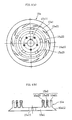
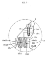
- Fig. 3 shows a fluidized bed apparatus according to another embodiment of the present invention. This embodiment adopts a disintegrator mechanism 15 equipped with a rotor 15a and a stator (outer stator 15b, an inner stator 15c) each having a plurality of teeth. As shown in Fig.
- the rotor 15a includes a disk-shaped base portion 15a1 and multiple comb-teeth 15a2 extending upward integrally from the upper surface of the base portion 15a1.
- a boss portion 15a11 that is key-coupled to the rotary shaft 5c, for example.
- a tapered surface 15a12 inclined toward the lower surface side.
- the comb-teeth 15a2 consist of outer teeth 15a21, intermediate teeth 15a22, and inner teeth 15a23 that are concentrically arranged.
- the outer teeth 15a21, the intermediate teeth 15a22, and the inner teeth 15a23 are arranged in a scattered formation at predetermined circumferential intervals from one another.
- the rotor 15a is coupled to the rotary shaft 5c, with its lower surface abutted on the upper surface of the rotary rotor 4.
- the outer stator 15b includes multiple teeth 15b1 arranged at a predetermined circumferential interval, a lower annular portion 15b2 integrally connecting the lower ends of respective teeth 15b1, an upper annular portion 15b3 integrally connecting the upper ends of respective teeth 15b1, and a flange 15b4 provided integrally with the upper annular portion 15b3.
- a window-like space 15b5 is formed between circumferentially adjacent teeth 15b1, 15b1.
- the inner stator 15c includes multiple teeth 15c1 arranged at a predetermined circumferential interval, a lower annular portion 15c2 integrally connecting the lower ends of respective teeth 15c1, an upper annular portion 15c3 integrally connecting the upper ends of respective teeth 15c1, and a flange 15c4 provided integrally with the upper annular portion 15c3.
- a window-like space 15c5 is formed between circumferentially adjacent teeth 15c1, 15c1.
- the pitch diameter of the teeth 15c1 of the inner stator 15c is smaller than the pitch diameter of the teeth 15b1 of the outer stator 15b.
- the outer stator 15b and the inner stator 15c are fixed to the lower end portion of the draft tube 6 with a bolt 16 such that the teeth 15c1 are incorporated into position on the inner peripheral side with respect to the teeth 15b1, with the flange 15b4 being abutted on the lower surface of the flange 15c4.
- the teeth 15b1 of the outer stator 15b are inserted in between the outer teeth 15a21 and the intermediate teeth 15a22 of the rotor 15a through the intermediation of a predetermined gap therebetween
- the teeth 15c1 of the inner stator 15c are inserted in between the intermediate teeth 15a22 and the inner teeth 15a23 of the rotor 15a through the intermediation of a predetermined gap therebetween.
- the portions of the powder particles forming secondary agglomerates or aggregates are disintegrated into single particles or particles of a predetermined particle size.
- the powder particles After passing the disintegrator mechanism 15, the powder particles are returned by the centrifugal force of the rotary rotor 4 to the upward current ascending in the space between the outer periphery of the draft tube 6 and the inner wall of the processing container 1.
- the tapered surface 15a12 is provided in the outer peripheral portion of the rotor 15a, whereby the powder particles having passed the disintegrator mechanism 15 can be smoothly carried onto the upper surface of the rotary rotor 4 due to the guiding action of the tapered surface 15a12.
- a vane-like member 17 which generates an up-to-down flow of air current as it rotates, is fitted to an upper end portion of the rotary shaft 5c.
- the turbulence effect of the disintegrator mechanism 15 combined with the sucking action of the air current generated by the rotation of the vane-like member 17 makes it possible to effectively suck the powder particles in the vicinity of the upper end portion of the draft tube 6 into the draft tube 6.
- a conical tapered guide surface 1a with a diameter gradually decreasing upwards is provided on the inner wall portion of the processing container 1 which is situated near the upper end portion of the draft tube 6.
Landscapes
- Chemical & Material Sciences (AREA)
- Organic Chemistry (AREA)
- Chemical Kinetics & Catalysis (AREA)
- Engineering & Computer Science (AREA)
- Combustion & Propulsion (AREA)
- Devices And Processes Conducted In The Presence Of Fluids And Solid Particles (AREA)
- Glanulating (AREA)
- Drying Of Solid Materials (AREA)
- Fertilizers (AREA)
Claims (4)
- Wirbelschichtvorrichtung, mit:einem Verarbeitungsbehälter (1);
einer Gasdispersionsplatte (3), die an einem Boden des Verarbeitungsbehälters (1) angeordnet ist;
einem drehbaren Rotor (4), der in der Bodenmitte des Verarbeitungsbehälters (1) derart angeordnet ist, dass er eine obere Fläche der Gasdispersionsplatte (3) mit einem dazwischen gebildeten, vorherbestimmten Spalt abdeckt;
einem Zerkleinerungsmechanismus (5, 15), der oberhalb des drehbaren Rotors (4) angeordnet ist, um Agglomerate von Pulverpartikeln durch eine mechanische Zerkleinerungskraft zu dispergieren; und
einem Saugrohr (6), das oberhalb des Zerkleinerungsmechanismus (5, 15) angeordnet ist;einem Gaszufuhrmittel zum Einleiten eines Wirbelgases durch die Gasdispersionsplatte (3) in den Verarbeitungsbehälter (1), um eine Wirbelschicht aus Pulverpartikeln in dem Verarbeitungsbehälter (1) zu bilden, in dem die Pulverpartikel so zirkulieren, dass sie durch einen Raum zwischen einer Innenwand des Verarbeitungsbehälters (1) und dem Saugrohr (6) aufsteigen und durch einen Innenbereich des Saugrohrs (6) absteigen, undeiner Sprühdüse (7), um eine Sprühlösung an einer Position auf die Pulverpartikel zu sprühen, an der die Pulverpartikel sich an dem Zerkleinerungsmechanismus (5, 15) vorbeibewegt haben und durch die Zentrifugalkraft des drehbaren Rotors (4) in eine aufwärts gerichtete Strömung des Wirbelgases geschickt werden. - Wirbelschichtvorrichtung nach Anspruch 1, dadurch gekennzeichnet, dass der Zerkleinerungsmechanismus (5) ein Flügelrad (5a) mit einem Zerkleinerungsflügel (5a1) aufweist.
- Wirbelschichtvorrichtung nach Anspruch 2, dadurch gekennzeichnet, dass der Zerkleinerungsmechanismus (5) außerdem eine Trennwand (5b) aufweist, die mit einem vorherbestimmten Spalt zu dem Zerkleinerungsflügel (5a1) des Flügelrads (5a) angeordnet ist.
- Wirbelschichtvorrichtung nach Anspruch 1, dadurch gekennzeichnet, dass der Zerkleinerungsmechanismus (15) einen Rotor (15a) und einen Stator (15b und 15c) aufweist, die jeweils eine Vielzahl konzentrisch angeordneter Zähne besitzen.
Applications Claiming Priority (5)
| Application Number | Priority Date | Filing Date | Title |
|---|---|---|---|
| JP2002259096 | 2002-09-04 | ||
| JP2002259096 | 2002-09-04 | ||
| JP2003184917A JP4015593B2 (ja) | 2002-09-04 | 2003-06-27 | 流動層装置 |
| JP2003184917 | 2003-06-27 | ||
| PCT/JP2003/009712 WO2004022217A1 (ja) | 2002-09-04 | 2003-07-30 | 流動層装置 |
Publications (3)
| Publication Number | Publication Date |
|---|---|
| EP1550502A1 EP1550502A1 (de) | 2005-07-06 |
| EP1550502A4 EP1550502A4 (de) | 2006-09-27 |
| EP1550502B1 true EP1550502B1 (de) | 2013-11-20 |
Family
ID=31980578
Family Applications (1)
| Application Number | Title | Priority Date | Filing Date |
|---|---|---|---|
| EP03794072.3A Expired - Lifetime EP1550502B1 (de) | 2002-09-04 | 2003-07-30 | Wirbelbettvorrichtung |
Country Status (7)
| Country | Link |
|---|---|
| US (1) | US7297314B2 (de) |
| EP (1) | EP1550502B1 (de) |
| JP (1) | JP4015593B2 (de) |
| CN (1) | CN1277600C (de) |
| AU (1) | AU2003252745A1 (de) |
| CA (1) | CA2495302C (de) |
| WO (1) | WO2004022217A1 (de) |
Families Citing this family (26)
| Publication number | Priority date | Publication date | Assignee | Title |
|---|---|---|---|---|
| JP4685400B2 (ja) * | 2004-09-30 | 2011-05-18 | 株式会社パウレック | 粒子のコーティング方法 |
| DE102006005382A1 (de) * | 2006-02-03 | 2007-08-16 | Glatt Gmbh | Messung, Überwachung und Regelung gerichteter Produktbewegungen in Wirbel- oder Strahlschichtanlagen und geeignete Anlagen |
| JP2008013480A (ja) * | 2006-07-05 | 2008-01-24 | Sawai Pharmaceutical Co Ltd | 薬物含有微粒子およびその製造方法 |
| DE102006053375A1 (de) * | 2006-11-10 | 2008-05-15 | Boehringer Ingelheim Pharma Gmbh & Co. Kg | Verfahren zur Mischung von Pulvern |
| US7908765B2 (en) * | 2006-12-22 | 2011-03-22 | Collette Nv | Continuous granulating and drying apparatus |
| JP4963420B2 (ja) * | 2007-02-06 | 2012-06-27 | キヤノン株式会社 | キャリア及びキャリアの製造方法 |
| JP4931222B2 (ja) * | 2007-03-29 | 2012-05-16 | パウダーテック株式会社 | 電子写真現像剤用樹脂コートキャリアの製造方法 |
| ES2666896T3 (es) | 2007-12-24 | 2018-05-08 | Borealis Technology Oy | Sistema reactor y proceso para la polimerización catalítica de olefinas y el uso de tal sistema reactor en la polimerización catalítica de olefinas |
| EP2082797A1 (de) * | 2007-12-24 | 2009-07-29 | Borealis Technology OY | Reaktorsystem für die katalytische Polymerisierung von Olefinen mit Abschirmmitteln und Verfahren und Verwendung davon |
| JP4914850B2 (ja) * | 2008-02-13 | 2012-04-11 | 株式会社リコー | 粉体処理装置 |
| JP5872140B2 (ja) | 2010-03-25 | 2016-03-01 | 住友ベークライト株式会社 | 粒子製造方法および半導体封止用樹脂組成物の製造方法 |
| FR2977259B1 (fr) | 2011-06-28 | 2013-08-02 | Commissariat Energie Atomique | Dispositif a profil specifique de reacteur de type lit a jet pour depot par cvd |
| AU2014309005A1 (en) * | 2013-08-19 | 2016-03-24 | The Mosaic Company | System and methods for addition of beneficial agricultural, biological, and/or dedusting additives to granular fertilizers |
| JP6345985B2 (ja) * | 2014-05-01 | 2018-06-20 | 小林 博 | 粉体ないしは粒子の表面を微細粒子の集まりで覆う表面処理装置 |
| US9751099B2 (en) * | 2014-06-10 | 2017-09-05 | Freund-Victor Corporation | Wurster accelerator with powder applicator |
| BR112017000358A2 (en) | 2014-07-07 | 2018-06-26 | The Mosaic Company | incorporation of biological agents in fertilizers |
| US10487016B2 (en) | 2015-08-12 | 2019-11-26 | The Mosaic Company | Acid treatment for fertilizers to increase zinc solubility and availability |
| JP6067154B1 (ja) * | 2016-01-25 | 2017-01-25 | 株式会社樋口商会 | コーティング粒子の製造方法 |
| CN108854869B (zh) * | 2017-05-10 | 2023-10-31 | 中国石油天然气集团公司 | 一种细粉提升装置 |
| JP7194375B2 (ja) * | 2017-06-29 | 2022-12-22 | アリメント工業株式会社 | 被覆粉末食品及びその製造方法 |
| CN107552204B (zh) * | 2017-09-28 | 2024-04-30 | 天津西敦粉漆科技有限公司 | 一种空气分级磨粉碎装置 |
| JP7698176B2 (ja) * | 2020-09-15 | 2025-06-25 | 株式会社パウレック | ゼラチン粒子製造方法およびゼラチン粒子製造装置 |
| CN112691765A (zh) * | 2021-01-05 | 2021-04-23 | 福汕生物科技(河北)有限公司 | 一种富硒木耳加工用破壁装置及其使用方法 |
| CN114210522B (zh) * | 2021-12-23 | 2023-02-28 | 成都华川电装有限责任公司 | 无轴式旋转涂覆装置 |
| CN117548041B (zh) * | 2024-01-11 | 2024-04-02 | 淄博鲁华泓锦新材料集团股份有限公司 | 化工用催化反应设备 |
| CN118577354B (zh) * | 2024-06-18 | 2025-10-17 | 中钢集团马鞍山矿山研究总院股份有限公司 | 一种制备超细粉体球磨机的衬板及其制造方法 |
Family Cites Families (8)
| Publication number | Priority date | Publication date | Assignee | Title |
|---|---|---|---|---|
| JPS5365272A (en) * | 1976-11-24 | 1978-06-10 | Okawara Mfg | Granule manufacturing apparatus |
| US5227136A (en) * | 1986-02-07 | 1993-07-13 | Envirotech Corporation | Bioslurry reactor for treatment of slurries containing minerals, soils and sludges |
| JPH01284329A (ja) * | 1988-05-09 | 1989-11-15 | Kawasaki Heavy Ind Ltd | 微粒体を造粒、コーティングおよび乾燥させる方法および装置 |
| DE59201645D1 (de) * | 1991-07-11 | 1995-04-20 | Glatt Gmbh | Verfahren und Einrichtung zum Beschichten von Teilchen. |
| JP3477581B2 (ja) * | 1993-06-29 | 2003-12-10 | 不二パウダル株式会社 | 造粒方法 |
| DE4435839A1 (de) * | 1994-10-07 | 1996-04-11 | Bayer Ag | Schlammphasenreaktor und dessen Verwendung |
| US5779996A (en) * | 1995-04-21 | 1998-07-14 | Innovative Biosystems, Inc. | Microbial remediation reactor and process |
| JP3827452B2 (ja) | 1998-08-14 | 2006-09-27 | トッパン・フォームズ株式会社 | 連続プリント方法 |
-
2003
- 2003-06-27 JP JP2003184917A patent/JP4015593B2/ja not_active Expired - Lifetime
- 2003-07-30 AU AU2003252745A patent/AU2003252745A1/en not_active Abandoned
- 2003-07-30 WO PCT/JP2003/009712 patent/WO2004022217A1/ja not_active Ceased
- 2003-07-30 CN CN03800262.0A patent/CN1277600C/zh not_active Expired - Lifetime
- 2003-07-30 US US10/526,248 patent/US7297314B2/en not_active Expired - Lifetime
- 2003-07-30 CA CA002495302A patent/CA2495302C/en not_active Expired - Lifetime
- 2003-07-30 EP EP03794072.3A patent/EP1550502B1/de not_active Expired - Lifetime
Also Published As
| Publication number | Publication date |
|---|---|
| CN1522172A (zh) | 2004-08-18 |
| AU2003252745A1 (en) | 2004-03-29 |
| JP2004148291A (ja) | 2004-05-27 |
| WO2004022217A1 (ja) | 2004-03-18 |
| JP4015593B2 (ja) | 2007-11-28 |
| EP1550502A1 (de) | 2005-07-06 |
| CA2495302A1 (en) | 2004-03-18 |
| CN1277600C (zh) | 2006-10-04 |
| EP1550502A4 (de) | 2006-09-27 |
| CA2495302C (en) | 2009-01-13 |
| US7297314B2 (en) | 2007-11-20 |
| US20060104871A1 (en) | 2006-05-18 |
Similar Documents
| Publication | Publication Date | Title |
|---|---|---|
| US7297314B2 (en) | Fluidized bed device | |
| JP2752378B2 (ja) | 噴霧乾燥機 | |
| JP2566884Y2 (ja) | 粉砕機 | |
| NL8303584A (nl) | Machine voor het granuleren en bekleden. | |
| EP0958043B1 (de) | Vorrichtung und verfahren zur behandlung teilchenförmiger materialien | |
| US4967688A (en) | Powder processing apparatus | |
| EP0328074A2 (de) | Gasstrom-Klassierabscheider | |
| JP4440278B2 (ja) | 流動層装置 | |
| JP2004122057A (ja) | 流動層装置 | |
| US4218411A (en) | Method and apparatus for producing particulate sulfur | |
| JP4685400B2 (ja) | 粒子のコーティング方法 | |
| JP4028121B2 (ja) | 整粒機 | |
| JP2003265975A (ja) | 乾式メディア撹拌型粉砕機 | |
| JP3271880B2 (ja) | 粉粒体処理装置 | |
| JP3640994B2 (ja) | 高速撹拌型分散機 | |
| JPH0411252B2 (de) | ||
| CN118923546B (zh) | 一种大颗粒饲料抛撒机 | |
| JP2003062475A (ja) | 固形物の粉砕方法および酸化粉砕品の製造方法とその設備 | |
| CN224087241U (zh) | 粉末流化涂装装置 | |
| JPH0615030B2 (ja) | 粉体処理装置 | |
| CN119926759A (zh) | 粉末流化涂装装置 | |
| JPH026860A (ja) | 連続流通攪拌装置 | |
| JPH0554376B2 (de) | ||
| JP3764950B2 (ja) | 微粒子コーティング・造粒装置 | |
| JP2746319B2 (ja) | 遠心流動粉砕装置 |
Legal Events
| Date | Code | Title | Description |
|---|---|---|---|
| PUAI | Public reference made under article 153(3) epc to a published international application that has entered the european phase |
Free format text: ORIGINAL CODE: 0009012 |
|
| 17P | Request for examination filed |
Effective date: 20050304 |
|
| AK | Designated contracting states |
Kind code of ref document: A1 Designated state(s): AT BE BG CH CY CZ DE DK EE ES FI FR GB GR HU IE IT LI LU MC NL PT RO SE SI SK TR |
|
| AX | Request for extension of the european patent |
Extension state: AL LT LV MK |
|
| DAX | Request for extension of the european patent (deleted) | ||
| A4 | Supplementary search report drawn up and despatched |
Effective date: 20060828 |
|
| RIN1 | Information on inventor provided before grant (corrected) |
Inventor name: NAGATO, TAKUYA Inventor name: WATANABE, NOBUYUKI Inventor name: TABATA, RAN Inventor name: KANOH, YOSHIYUKI Inventor name: KOBAYASHI, MAKOTO Inventor name: NAGATSUMA, KENJI Inventor name: NATSUYAMA, SUSUMU Inventor name: OTAKI, KAZUYOSHI |
|
| 17Q | First examination report despatched |
Effective date: 20071218 |
|
| GRAP | Despatch of communication of intention to grant a patent |
Free format text: ORIGINAL CODE: EPIDOSNIGR1 |
|
| INTG | Intention to grant announced |
Effective date: 20130605 |
|
| GRAS | Grant fee paid |
Free format text: ORIGINAL CODE: EPIDOSNIGR3 |
|
| GRAA | (expected) grant |
Free format text: ORIGINAL CODE: 0009210 |
|
| RAP1 | Party data changed (applicant data changed or rights of an application transferred) |
Owner name: KABUSHIKI KAISHA POWREX |
|
| AK | Designated contracting states |
Kind code of ref document: B1 Designated state(s): AT BE BG CH CY CZ DE DK EE ES FI FR GB GR HU IE IT LI LU MC NL PT RO SE SI SK TR |
|
| REG | Reference to a national code |
Ref country code: GB Ref legal event code: FG4D |
|
| REG | Reference to a national code |
Ref country code: CH Ref legal event code: EP |
|
| REG | Reference to a national code |
Ref country code: AT Ref legal event code: REF Ref document number: 641248 Country of ref document: AT Kind code of ref document: T Effective date: 20131215 |
|
| REG | Reference to a national code |
Ref country code: IE Ref legal event code: FG4D |
|
| REG | Reference to a national code |
Ref country code: DE Ref legal event code: R096 Ref document number: 60345338 Country of ref document: DE Effective date: 20140116 |
|
| REG | Reference to a national code |
Ref country code: NL Ref legal event code: VDEP Effective date: 20131120 |
|
| REG | Reference to a national code |
Ref country code: CH Ref legal event code: NV Representative=s name: TROESCH SCHEIDEGGER WERNER AG, CH |
|
| REG | Reference to a national code |
Ref country code: AT Ref legal event code: MK05 Ref document number: 641248 Country of ref document: AT Kind code of ref document: T Effective date: 20131120 |
|
| PG25 | Lapsed in a contracting state [announced via postgrant information from national office to epo] |
Ref country code: NL Free format text: LAPSE BECAUSE OF FAILURE TO SUBMIT A TRANSLATION OF THE DESCRIPTION OR TO PAY THE FEE WITHIN THE PRESCRIBED TIME-LIMIT Effective date: 20131120 Ref country code: SE Free format text: LAPSE BECAUSE OF FAILURE TO SUBMIT A TRANSLATION OF THE DESCRIPTION OR TO PAY THE FEE WITHIN THE PRESCRIBED TIME-LIMIT Effective date: 20131120 Ref country code: FI Free format text: LAPSE BECAUSE OF FAILURE TO SUBMIT A TRANSLATION OF THE DESCRIPTION OR TO PAY THE FEE WITHIN THE PRESCRIBED TIME-LIMIT Effective date: 20131120 |
|
| PG25 | Lapsed in a contracting state [announced via postgrant information from national office to epo] |
Ref country code: ES Free format text: LAPSE BECAUSE OF FAILURE TO SUBMIT A TRANSLATION OF THE DESCRIPTION OR TO PAY THE FEE WITHIN THE PRESCRIBED TIME-LIMIT Effective date: 20131120 Ref country code: AT Free format text: LAPSE BECAUSE OF FAILURE TO SUBMIT A TRANSLATION OF THE DESCRIPTION OR TO PAY THE FEE WITHIN THE PRESCRIBED TIME-LIMIT Effective date: 20131120 |
|
| PG25 | Lapsed in a contracting state [announced via postgrant information from national office to epo] |
Ref country code: PT Free format text: LAPSE BECAUSE OF FAILURE TO SUBMIT A TRANSLATION OF THE DESCRIPTION OR TO PAY THE FEE WITHIN THE PRESCRIBED TIME-LIMIT Effective date: 20140320 |
|
| PG25 | Lapsed in a contracting state [announced via postgrant information from national office to epo] |
Ref country code: EE Free format text: LAPSE BECAUSE OF FAILURE TO SUBMIT A TRANSLATION OF THE DESCRIPTION OR TO PAY THE FEE WITHIN THE PRESCRIBED TIME-LIMIT Effective date: 20131120 |
|
| REG | Reference to a national code |
Ref country code: DE Ref legal event code: R097 Ref document number: 60345338 Country of ref document: DE |
|
| PG25 | Lapsed in a contracting state [announced via postgrant information from national office to epo] |
Ref country code: CZ Free format text: LAPSE BECAUSE OF FAILURE TO SUBMIT A TRANSLATION OF THE DESCRIPTION OR TO PAY THE FEE WITHIN THE PRESCRIBED TIME-LIMIT Effective date: 20131120 Ref country code: SK Free format text: LAPSE BECAUSE OF FAILURE TO SUBMIT A TRANSLATION OF THE DESCRIPTION OR TO PAY THE FEE WITHIN THE PRESCRIBED TIME-LIMIT Effective date: 20131120 Ref country code: RO Free format text: LAPSE BECAUSE OF FAILURE TO SUBMIT A TRANSLATION OF THE DESCRIPTION OR TO PAY THE FEE WITHIN THE PRESCRIBED TIME-LIMIT Effective date: 20131120 |
|
| PLBE | No opposition filed within time limit |
Free format text: ORIGINAL CODE: 0009261 |
|
| STAA | Information on the status of an ep patent application or granted ep patent |
Free format text: STATUS: NO OPPOSITION FILED WITHIN TIME LIMIT |
|
| PG25 | Lapsed in a contracting state [announced via postgrant information from national office to epo] |
Ref country code: DK Free format text: LAPSE BECAUSE OF FAILURE TO SUBMIT A TRANSLATION OF THE DESCRIPTION OR TO PAY THE FEE WITHIN THE PRESCRIBED TIME-LIMIT Effective date: 20131120 |
|
| 26N | No opposition filed |
Effective date: 20140821 |
|
| REG | Reference to a national code |
Ref country code: DE Ref legal event code: R097 Ref document number: 60345338 Country of ref document: DE Effective date: 20140821 |
|
| PG25 | Lapsed in a contracting state [announced via postgrant information from national office to epo] |
Ref country code: LU Free format text: LAPSE BECAUSE OF FAILURE TO SUBMIT A TRANSLATION OF THE DESCRIPTION OR TO PAY THE FEE WITHIN THE PRESCRIBED TIME-LIMIT Effective date: 20140730 Ref country code: SI Free format text: LAPSE BECAUSE OF FAILURE TO SUBMIT A TRANSLATION OF THE DESCRIPTION OR TO PAY THE FEE WITHIN THE PRESCRIBED TIME-LIMIT Effective date: 20131120 |
|
| REG | Reference to a national code |
Ref country code: IE Ref legal event code: MM4A |
|
| PG25 | Lapsed in a contracting state [announced via postgrant information from national office to epo] |
Ref country code: IE Free format text: LAPSE BECAUSE OF NON-PAYMENT OF DUE FEES Effective date: 20140730 |
|
| PG25 | Lapsed in a contracting state [announced via postgrant information from national office to epo] |
Ref country code: MC Free format text: LAPSE BECAUSE OF FAILURE TO SUBMIT A TRANSLATION OF THE DESCRIPTION OR TO PAY THE FEE WITHIN THE PRESCRIBED TIME-LIMIT Effective date: 20131120 |
|
| PG25 | Lapsed in a contracting state [announced via postgrant information from national office to epo] |
Ref country code: BG Free format text: LAPSE BECAUSE OF FAILURE TO SUBMIT A TRANSLATION OF THE DESCRIPTION OR TO PAY THE FEE WITHIN THE PRESCRIBED TIME-LIMIT Effective date: 20131120 |
|
| PG25 | Lapsed in a contracting state [announced via postgrant information from national office to epo] |
Ref country code: CY Free format text: LAPSE BECAUSE OF FAILURE TO SUBMIT A TRANSLATION OF THE DESCRIPTION OR TO PAY THE FEE WITHIN THE PRESCRIBED TIME-LIMIT Effective date: 20131120 Ref country code: GR Free format text: LAPSE BECAUSE OF FAILURE TO SUBMIT A TRANSLATION OF THE DESCRIPTION OR TO PAY THE FEE WITHIN THE PRESCRIBED TIME-LIMIT Effective date: 20140221 |
|
| REG | Reference to a national code |
Ref country code: FR Ref legal event code: PLFP Year of fee payment: 14 |
|
| PG25 | Lapsed in a contracting state [announced via postgrant information from national office to epo] |
Ref country code: TR Free format text: LAPSE BECAUSE OF FAILURE TO SUBMIT A TRANSLATION OF THE DESCRIPTION OR TO PAY THE FEE WITHIN THE PRESCRIBED TIME-LIMIT Effective date: 20131120 Ref country code: HU Free format text: LAPSE BECAUSE OF FAILURE TO SUBMIT A TRANSLATION OF THE DESCRIPTION OR TO PAY THE FEE WITHIN THE PRESCRIBED TIME-LIMIT; INVALID AB INITIO Effective date: 20030730 |
|
| REG | Reference to a national code |
Ref country code: FR Ref legal event code: PLFP Year of fee payment: 15 |
|
| REG | Reference to a national code |
Ref country code: FR Ref legal event code: PLFP Year of fee payment: 16 |
|
| PGFP | Annual fee paid to national office [announced via postgrant information from national office to epo] |
Ref country code: GB Payment date: 20220601 Year of fee payment: 20 |
|
| PGFP | Annual fee paid to national office [announced via postgrant information from national office to epo] |
Ref country code: IT Payment date: 20220729 Year of fee payment: 20 Ref country code: DE Payment date: 20220531 Year of fee payment: 20 |
|
| PGFP | Annual fee paid to national office [announced via postgrant information from national office to epo] |
Ref country code: FR Payment date: 20220727 Year of fee payment: 20 Ref country code: BE Payment date: 20220720 Year of fee payment: 20 |
|
| PGFP | Annual fee paid to national office [announced via postgrant information from national office to epo] |
Ref country code: CH Payment date: 20220727 Year of fee payment: 20 |
|
| REG | Reference to a national code |
Ref country code: DE Ref legal event code: R071 Ref document number: 60345338 Country of ref document: DE |
|
| REG | Reference to a national code |
Ref country code: CH Ref legal event code: PL |
|
| REG | Reference to a national code |
Ref country code: BE Ref legal event code: MK Effective date: 20230730 |
|
| REG | Reference to a national code |
Ref country code: GB Ref legal event code: PE20 Expiry date: 20230729 |
|
| PG25 | Lapsed in a contracting state [announced via postgrant information from national office to epo] |
Ref country code: GB Free format text: LAPSE BECAUSE OF EXPIRATION OF PROTECTION Effective date: 20230729 |