EP1549542B1 - Glied zur befestigung einer fahrradantriebsvorrichtung - Google Patents
Glied zur befestigung einer fahrradantriebsvorrichtung Download PDFInfo
- Publication number
- EP1549542B1 EP1549542B1 EP03794718A EP03794718A EP1549542B1 EP 1549542 B1 EP1549542 B1 EP 1549542B1 EP 03794718 A EP03794718 A EP 03794718A EP 03794718 A EP03794718 A EP 03794718A EP 1549542 B1 EP1549542 B1 EP 1549542B1
- Authority
- EP
- European Patent Office
- Prior art keywords
- fixing member
- pivot pin
- fastener
- pivot
- drive device
- Prior art date
- Legal status (The legal status is an assumption and is not a legal conclusion. Google has not performed a legal analysis and makes no representation as to the accuracy of the status listed.)
- Expired - Lifetime
Links
- 238000000926 separation method Methods 0.000 claims 1
- 230000005540 biological transmission Effects 0.000 description 1
- 238000010276 construction Methods 0.000 description 1
- 229940082150 encore Drugs 0.000 description 1
- 230000005484 gravity Effects 0.000 description 1
- 238000004519 manufacturing process Methods 0.000 description 1
- 238000012986 modification Methods 0.000 description 1
- 230000004048 modification Effects 0.000 description 1
- 239000007787 solid Substances 0.000 description 1
Images



Classifications
-
- B—PERFORMING OPERATIONS; TRANSPORTING
- B62—LAND VEHICLES FOR TRAVELLING OTHERWISE THAN ON RAILS
- B62M—RIDER PROPULSION OF WHEELED VEHICLES OR SLEDGES; POWERED PROPULSION OF SLEDGES OR SINGLE-TRACK CYCLES; TRANSMISSIONS SPECIALLY ADAPTED FOR SUCH VEHICLES
- B62M13/00—Transmissions characterised by use of friction rollers engaging the periphery of the ground wheel
- B62M13/04—Transmissions characterised by use of friction rollers engaging the periphery of the ground wheel with means for moving roller into driving contact with ground wheel
-
- B—PERFORMING OPERATIONS; TRANSPORTING
- B62—LAND VEHICLES FOR TRAVELLING OTHERWISE THAN ON RAILS
- B62M—RIDER PROPULSION OF WHEELED VEHICLES OR SLEDGES; POWERED PROPULSION OF SLEDGES OR SINGLE-TRACK CYCLES; TRANSMISSIONS SPECIALLY ADAPTED FOR SUCH VEHICLES
- B62M6/00—Rider propulsion of wheeled vehicles with additional source of power, e.g. combustion engine or electric motor
- B62M6/40—Rider propelled cycles with auxiliary electric motor
- B62M6/75—Rider propelled cycles with auxiliary electric motor power-driven by friction rollers or gears engaging the ground wheel
Definitions
- the present invention relates to a bicycle wheel friction drive attachment member.
- Bike training systems provide help with pedaling by means of an additional motor.
- This aid generally consists of a drive mechanism arranged on one of the wheels of the bicycle.
- the power of the motor drives the wheel and adds to the power exerted by the pressure on the pedal, which allows the cyclist to provide less effort.
- Such a drive system according to the preamble of claim 1 is for example illustrated in the European patent EP-A-0155.185 .
- This known system is provided with a drive motor connected to one of the wheels of the bicycle via a drive wheel.
- the fastener of the driving device comprises a fastener to be connected to an element of the frame of the bicycle, the driving device being arranged so as to be pivotable about an axis provided on this attached.
- the object of the present invention is therefore to provide a bicycle wheel friction drive attachment member for easily adapting to each type of conventional bicycle.
- the drive device does not pivot directly relative to the frame of the bicycle or a fixed part relative to this frame, but unlike an intermediate piece, called the first part of the fastener, whose angular position relative to the second part can be previously adjusted.
- the driving device can adapt to the movement of the wheel relative to the frame of the bicycle, particularly when the latter is damped.
- the fixing member may be adapted by simple pivoting to the configuration of the frame, for example at the location of the attachment point or that of the drive device.
- the first pivot axis is located at a distance from the second pivot axis and the fixing member comprises distance modifying means between the first pivot axis and the second pivot axis.
- the first portion has a plurality of pivoting seats for optionally adjusting the position of the first pivot axis. In this way, we obtain a very easy adjustment and particularly adaptable to any bike model and at any location of the frame for the fastener and therefore the drive device.
- the fixing member may comprise at least one stop arranged to delimit a deflection angle between said drive device and said first part.
- the deflection angle thus defined reduces the risk that the drive device jumps disconnected from the wheel. Following its passage over an irregularity of the driving lane, the driving device can bounce on the bicycle tire and tilt around the first pivot point.
- the fixing member 1 comprises a first part 2 connected to the driving device 3 so as to be pivotable about a first pivot axis 4.
- a second part 5 is attached to the first part 2, in order to allow them to pivot one another about a second pivot axis 6.
- the second part also comprises a fastener 7 located at a predetermined distance from said second pivot axis 6.
- This fastener 7 may comprise, for example, two blocks 8, the first block having a concave face 9 placed facing the concave face of the second block and these blocks being connected by fastening means such as, for example, clamping screws 10. One of the blocks can be secured to the second part of the fastener.
- the operator can unscrew the clamping screws so as to separate the two blocks and place the solid block of the second part against the part of the bike on which the body is fixed. of fixation. Then, the operator can place the other block opposite and screw the clamping screws so as to fix the two blocks around the handlebar part.
- the shape of the sides of the blocks, coming into contact with the bicycle may vary so as to marry at best the edges of the place where the fastener will be fixed.
- the fastener 7 is itself releasably connected to the second portion 5 of the fastener. It can also be conceived, for example, that, as illustrated in figure 6 , the fastener is supported on the second part 5 by a pivot 21 to adapt the position of the fastener in the most appropriate manner on the frame member to which the fastener is to be attached.
- the pivot 21 is formed by one of the clamping bolts of the fastener 7.
- the drive device is composed of a motor 21, for example electric, connected to a drive wheel by a transmission means not shown, such as a chain or belt, the drive wheel acting on the tire of the bike by communicating to him his movement by friction.
- a transmission means not shown such as a chain or belt
- the first and second pivot axes may be coaxial along the near edge of the driving device.
- a single axis could serve as a pivot for the movement between the drive device and the assembly consisting of the first and the second part. This embodiment could be more economical to manufacture.
- first part 2 of the fixing member may also comprise a series of holes 12 close to the drive device. These holes representing different pivoting seats allow additional adjustment for the placement of the driving device. In fact, these holes make it possible to modify the location of the first pivot axis and thus to adjust the length between the fastener and the drive device so as to better position the wheel on the bicycle tire according to the configuration of the bicycle (see for example the different positions illustrated on the figures 2 and 3 ).
- the fixing member may also comprise at least one stop arranged to define a deflection angle between said drive device and said first part.
- the fixing member comprises two stops, the first stop 13 being one of the sides of the first part 2 of the fixing member and the second stop 15 being located on the other side of the fixing member.
- the driving device when the driving device rebounds, for example following a bump encountered by the wheel, it tilts around the first pivot axis 4, so as to be stopped by the first stop 13.
- the shell 14 of the driving device meets the side 13 which stops it in its rotary movement and allows the drive device to fall back to the wheel by gravity.
- the fixing member may also be provided with a current elastic means, not shown, which forces, with a certain degree of freedom, the drive device to remain essentially in contact with the wheel.
- the second stop 15 allows the driving device, when the wheel crashes or escapes violently under the driving device, to be stopped at a certain angle of movement so that when the wheel returns to its position initially, the training device does not come to meet the wheel too violently. For example, if the inclination of the driving device with respect to the deflection axis of the wheel was 90 ° or more, the encounter between the wheel and the driving device could cause significant stresses in the first axis swivel that could twist or break it.
- the fixing member also comprises adjustment means 16 which comprise, on one of the parts of the fastener, for example on the second part 5, at least a first orifice 17 extending in an arc of curvature having as a center the second pivot axis 6 and a second orifice 18, for example located on the first part 2 of the fastener.
- This second orifice 18 is arranged to be placed in front of one of said at least one first orifice.
- a holding and clamping means is arranged to engage the first port 17 and the second port 18 to thereby maintain the two integral parts of each other after tightening.
- the holding means 19 comprise a nut and a bolt.
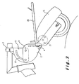
- the fastener can adapt to different bike configurations. So, as represented on the figure 2 , the fastener makes it possible to attach the driving device to a substantially vertical bar of a bicycle. It is also possible, as shown on the figure 3 , to attach the fastener on a substantially horizontal bar of the bicycle.
- the cyclist rotates mutually around the second pivot axis 6 the second portion 5 and the first portion 2 of the fastener. Then, in the appropriate angular position, the fastening means 19, in this case a nut and a bolt, are tightened so as to support the first part on the second which jointly secures these two parts.
- the drive device may comprise a shell provided with a luggage rack 20, the luggage carrier being preferably arranged to carry a bag placed astride the luggage carrier.
- the bag may for example comprise two locations, each arranged to contain for example batteries supplying the motor of the driving device. When the bag is straddling the rack, the batteries will be placed to balance the weight on both sides of the drive.
- the first part 2 consists of two parts 22 and 23 capable of sliding relative to each other, for example telescopically.
- the first part 22 is hollow and supports the drive device 3 by allowing it to pivot about the axis 4.
- the second part 23 slides inside the first part 22 and is connected to the second part 5 so as to allow mutual pivoting.
- a clamping bolt 25 supported by the first piece 22 can be passed and tightened.
- the bolt 25 can be tightened to lock the two parts in this position.
- the first portion 2 has at one end a circular detent 26 whose center is formed by the pivot axis 6.
- the second portion 5 has a corresponding detent 27 whose center is also formed by the pivot axis 6
- each of the parts has orifices which extend along equal circular arcs concentric with the axis. It is thus possible by a clamping bolt to fix the mutual angular position of the two parts of the fastener.
- the axis of the motor 21 is the axis of the wheel 11.
Landscapes
- Engineering & Computer Science (AREA)
- Chemical & Material Sciences (AREA)
- Combustion & Propulsion (AREA)
- Transportation (AREA)
- Mechanical Engineering (AREA)
- Axle Suspensions And Sidecars For Cycles (AREA)
- Steering Devices For Bicycles And Motorcycles (AREA)
- Transmission Devices (AREA)
- Fittings On The Vehicle Exterior For Carrying Loads, And Devices For Holding Or Mounting Articles (AREA)
- Motorcycle And Bicycle Frame (AREA)
- Automatic Cycles, And Cycles In General (AREA)
- Lock And Its Accessories (AREA)
Claims (8)
- Steckhülse (1) für den Antrieb durch Reibung des Fahrradrads einschließlich- einer Klemme (7), die mit einem Rahmenelement des Fahrrads verbunden ist.- der Antrieb durch Reibung (3) ist darauf ausgelegt, um eine erste Umdrehungsachse (4) frei schwenken zu können, und
"dadurch gekennzeichnet, dass die Steckhülse Folgendes umfasst":- einen ersten Teil (2), mit dem der Antrieb in einer Weise verbunden ist, in der er um die genannte erste Umdrehungsachse (4) frei schwenken kann,- einen zweiten Teil (5), der mit dem ersten Teil (2) auf eine Weise verbunden ist, in der
beide Teile untereinander um eine zweite Umdrehungsachse (6) schwenken können, bevor der erste (2) und der zweite Teil (5) gemeinsam angezogen und zusammengehalten werden, die Steckhülse umfasst darüber hinaus, im Abstand von der zweiten Umdrehungsachse, die genannte Klemme (7). Die Steckhülse ist mit dem genannten Rahmenelement durch die genannte Klemme (7) verbunden, und- Einstellinstrumente (17 - 19; 26 - 27), die den ersten Teil (2) im Verhältnis zum zweiten Teil (5) in einer durch die genannte, gegenseitige Verschwenkung einstellbaren Winkelposition halten kann. Dadurch wird der erste Teil (2) nach Einstellung relativ zum zweiten Teil (5) befestigt. "..."- Instrumenten zur Änderung des Abstands (22 - 25) zwischen der ersten Umdrehungsachse (4) und der zweiten Umdrehungsachse (6), um die Länge zwischen Klemme und Antrieb in einer Weise einstellen zu können, in der das Antriebsrad bestmöglich entsprechend der Konfiguration des Fahrrads am Fahrradpneu angeordnet wird. - Steckhülse gemäß der Anforderung 1, die dadurch gekennzeichnet ist, dass der erste Teil (2) aus zwei Teilen (22, 23) besteht, die relativ zueinander gleiten können. Einer (22) der beiden Teile trägt den Antrieb (3). Dadurch wird ermöglicht, dass dieses Teil um die erste Umdrehungsachse (4) schwenken kann. Das andere Teil (23) ist mit dem zweiten Teil (5) in einer Weise verbunden, durch die die genannte, gegenseitige Verschwenkung ermöglicht wird.
- Steckhülse gemäß allen Anforderungen 1 bis 2, die dadurch gekennzeichnet ist, dass sie mindestens einen Anschlag (13) umfasst, der darauf ausgelegt ist, zwischen dem genannten Antrieb und dem genannten ersten Teil einen Schwenkwinkel zu begrenzen.
- Steckhülse gemäß den Anforderungen 1 bis 3, die dadurch gekennzeichnet ist, dass die genannten Einstellinstrumente, auf einem der Teile der Steckhülse, mindestens eine Öffnung (17) umfassen, die sich entsprechend einem Bogen erstreckt, dessen Zentrum die zweite Umdrehungsachse (6) ist. Die Einstellinstrumente umfassen auf dem anderen Teil eine zweite Öffnung (18), die gegenüber mindestens einem des Genannten mindestens eine erste Öffnung (17) umfasst, sowie Instrumente zum Halten und Anziehen (19), die darauf ausgelegt sind, sich im Genannten mindestens durch eine erste Öffnung (17) und in der genannten zweiten Öffnung (18) einzubiegen, und dadurch die beiden, so genannten integrierten Teile nach dem Anziehen zu tragen.
- Steckhülse entsprechend einer der Anforderungen 1 bis 3, die dadurch gekennzeichnet ist, dass die genannten Einstellinstrumente, auf einem der beiden Teile der Steckhülse, eine erste Riffelung (26) umfassen, die sich entsprechend einem ersten Bogen erstreckt, dessen Zentrum die zweite Umdrehungsachse (6) ist. Auf dem zweiten Teil befindet sich eine zweite Riffelung (27), die mit der ersten Riffelung gemeinsam funktionieren kann und sich entsprechend einem zweiten Bogen erstreckt, dessen Zentrum die zweite Umdrehungsachse ist (6). Instrumente zum Anzug der beiden Teile sind mit ihren jeweiligen, sich gegenseitig ineinander einbiegenden Riffelungen, ebenfalls zugehörig.
- Steckhülse entsprechend einer der Anforderungen 1 bis 2, die dadurch gekennzeichnet ist, dass der genannte Antrieb (3) einen Motor (21) umfasst, der darauf ausgelegt ist, ein Antriebsrad (11), das durch Reibung auf das Fahrradrad einwirkt, in Rotation zu bringen.
- Steckhülse entsprechend den Anforderungen 1 bis 6, die dadurch gekennzeichnet ist, dass der erste Teil (2) mehrere Schwenkpositionen (12) aufweist, um die Position der ersten Umdrehungsachse (4) nach Wunsch einstellen zu können.
- Steckhülse entsprechend den Anforderungen 1 bis 7, die dadurch gekennzeichnet ist, dass durch die genannte Klemme (7) im zweiten Teil (5) ein Zwischenelement (28) winklig einstellbar befestigt wird.
Priority Applications (1)
| Application Number | Priority Date | Filing Date | Title |
|---|---|---|---|
| EP03794718A EP1549542B8 (de) | 2002-09-12 | 2003-09-11 | Glied zur befestigung einer fahrradantriebsvorrichtung |
Applications Claiming Priority (4)
| Application Number | Priority Date | Filing Date | Title |
|---|---|---|---|
| EP02447175A EP1398265A1 (de) | 2002-09-12 | 2002-09-12 | Befestigung für eine Fahrrad-Antriebseinheit |
| EP02447175 | 2002-09-12 | ||
| PCT/BE2003/000150 WO2004024549A1 (fr) | 2002-09-12 | 2003-09-11 | Organe de fixation de dispositif d'entrainement de velo |
| EP03794718A EP1549542B8 (de) | 2002-09-12 | 2003-09-11 | Glied zur befestigung einer fahrradantriebsvorrichtung |
Publications (3)
| Publication Number | Publication Date |
|---|---|
| EP1549542A1 EP1549542A1 (de) | 2005-07-06 |
| EP1549542B1 true EP1549542B1 (de) | 2010-12-08 |
| EP1549542B8 EP1549542B8 (de) | 2011-09-21 |
Family
ID=31725559
Family Applications (2)
| Application Number | Title | Priority Date | Filing Date |
|---|---|---|---|
| EP02447175A Withdrawn EP1398265A1 (de) | 2002-09-12 | 2002-09-12 | Befestigung für eine Fahrrad-Antriebseinheit |
| EP03794718A Expired - Lifetime EP1549542B8 (de) | 2002-09-12 | 2003-09-11 | Glied zur befestigung einer fahrradantriebsvorrichtung |
Family Applications Before (1)
| Application Number | Title | Priority Date | Filing Date |
|---|---|---|---|
| EP02447175A Withdrawn EP1398265A1 (de) | 2002-09-12 | 2002-09-12 | Befestigung für eine Fahrrad-Antriebseinheit |
Country Status (8)
| Country | Link |
|---|---|
| US (1) | US7441621B2 (de) |
| EP (2) | EP1398265A1 (de) |
| CN (1) | CN100357154C (de) |
| AT (1) | ATE490903T1 (de) |
| AU (1) | AU2003264185A1 (de) |
| DE (1) | DE60335277D1 (de) |
| TW (1) | TWI305522B (de) |
| WO (1) | WO2004024549A1 (de) |
Families Citing this family (10)
| Publication number | Priority date | Publication date | Assignee | Title |
|---|---|---|---|---|
| BE1016004A6 (fr) * | 2004-05-04 | 2006-01-10 | Motte Dit Falisse Gilles Jacqu | Dispositif de fixation universel d'un moteur d'entrainement pour roue. |
| CA128695S (en) * | 2008-11-26 | 2009-08-12 | Beta Calco Inc | Light fixture |
| US20110114407A1 (en) * | 2009-11-16 | 2011-05-19 | Chih Hsing Lee | Bicycle-running assistant system |
| US20110232985A1 (en) * | 2010-03-26 | 2011-09-29 | Chih Hsing Lee | Power drive assistant system for bicycle |
| EP2447145B1 (de) * | 2010-10-29 | 2014-01-01 | Günther Hirn | Elektroantrieb für Fahrräder |
| LT6125B (lt) | 2013-07-11 | 2015-03-25 | Uab "Elinta" | Elektrinė frikcinė dviračio pavara |
| US9758214B2 (en) | 2014-02-01 | 2017-09-12 | Shareroller Llc. | Portable multi-platform friction drive system with retractable motor drive assembly |
| US10005518B2 (en) | 2015-10-19 | 2018-06-26 | ShareRoller LLC | Automatic traction control for friction drives |
| US10279865B2 (en) * | 2016-08-08 | 2019-05-07 | Shareroller Llc. | Friction drive with speed wheel and automatic traction control |
| SE541446C2 (en) * | 2017-09-26 | 2019-10-01 | Zipforce Ab | Electric friction drive device and electric drive system |
Family Cites Families (18)
| Publication number | Priority date | Publication date | Assignee | Title |
|---|---|---|---|---|
| JPS577955B2 (de) * | 1973-09-11 | 1982-02-13 | ||
| US3978936A (en) * | 1974-07-11 | 1976-09-07 | Schwartz Theodore F | Bicycle drive means |
| FR2346178A1 (fr) | 1976-04-01 | 1977-10-28 | Depoilly Ricard | Dispositif pour solidariser temporairement sur son support un moteur monte oscillant |
| US4172504A (en) * | 1977-04-19 | 1979-10-30 | Tanaka Kogyo Kabushiki Kaisha | Bicycle engine |
| US4418784A (en) * | 1982-01-26 | 1983-12-06 | Duke Fox | Bicycle transmission assembly |
| GB8406726D0 (en) | 1984-03-15 | 1984-04-18 | Baker A | Electrically assisted cycle |
| US4579188A (en) * | 1984-11-09 | 1986-04-01 | Facer Robert H | Multi-speed transmission for friction driven cycles |
| CH685757A5 (de) | 1992-02-20 | 1995-09-29 | Nose Design Intelligence | Fahrradgepäckträger. |
| WO1994020357A1 (en) * | 1993-03-11 | 1994-09-15 | Randall Bruce Olsen | Bicycle power assist |
| EP0644110A2 (de) * | 1993-09-16 | 1995-03-22 | Sinclair Research Limited | Antriebseinrichtung für Fahrrad |
| US5423393A (en) * | 1993-11-12 | 1995-06-13 | Felt; Robert M. | Auxiliary engine assembly for a bicycle |
| US5491390A (en) * | 1994-01-18 | 1996-02-13 | Mcgreen; James R. | Electric propulsion system for a bicycle |
| US6102148A (en) * | 1998-10-21 | 2000-08-15 | Chien; Hsi-Hai | Electrically powered bicycle driving mechanism |
| IL127961A0 (en) * | 1999-01-07 | 1999-11-30 | Arie Becker | A kit for converting a muscle-powered vehicle into a motor-assisted vehicle |
| GB9904272D0 (en) * | 1999-02-24 | 1999-04-21 | Sinclair Res Ltd | Drive apparatus for a cycle |
| US6192773B1 (en) | 1999-04-21 | 2001-02-27 | Hsin Lung Accessories Co., Ltd. | Stem for a bicycle |
| DE29921956U1 (de) | 1999-12-16 | 2000-03-23 | Weidner, Frank, 71229 Leonberg | Vario-Vorbausystem für eine Fahrradgabel |
| TW443285U (en) | 2000-06-21 | 2001-06-23 | J D Components Co Ltd | Power clutch mechanism for scooter |
-
2002
- 2002-09-12 EP EP02447175A patent/EP1398265A1/de not_active Withdrawn
-
2003
- 2003-09-10 TW TW092125002A patent/TWI305522B/zh not_active IP Right Cessation
- 2003-09-11 CN CNB038217090A patent/CN100357154C/zh not_active Expired - Fee Related
- 2003-09-11 DE DE60335277T patent/DE60335277D1/de not_active Expired - Lifetime
- 2003-09-11 AU AU2003264185A patent/AU2003264185A1/en not_active Abandoned
- 2003-09-11 EP EP03794718A patent/EP1549542B8/de not_active Expired - Lifetime
- 2003-09-11 AT AT03794718T patent/ATE490903T1/de not_active IP Right Cessation
- 2003-09-11 US US10/526,542 patent/US7441621B2/en not_active Expired - Fee Related
- 2003-09-11 WO PCT/BE2003/000150 patent/WO2004024549A1/fr not_active Ceased
Also Published As
| Publication number | Publication date |
|---|---|
| AU2003264185A1 (en) | 2004-04-30 |
| ATE490903T1 (de) | 2010-12-15 |
| TW200408578A (en) | 2004-06-01 |
| US20050269146A1 (en) | 2005-12-08 |
| TWI305522B (en) | 2009-01-21 |
| EP1398265A1 (de) | 2004-03-17 |
| US7441621B2 (en) | 2008-10-28 |
| EP1549542B8 (de) | 2011-09-21 |
| EP1549542A1 (de) | 2005-07-06 |
| CN1681703A (zh) | 2005-10-12 |
| WO2004024549A1 (fr) | 2004-03-25 |
| DE60335277D1 (de) | 2011-01-20 |
| CN100357154C (zh) | 2007-12-26 |
Similar Documents
| Publication | Publication Date | Title |
|---|---|---|
| FR2719748A1 (fr) | Dispositif de fixation occipitale d'un casque. | |
| EP3552939B1 (de) | Aerodanymische anordnung für fahrradlenker | |
| FR2723561A1 (fr) | Bicyclette comportant un cadre a articulation | |
| FR2794422A3 (fr) | Frein a disque avant pour bicyclette | |
| EP0068538A2 (de) | Einstellvorrichtung der Stellung von Fussstützen für Motorfahrräder | |
| EP3187402B1 (de) | Sattelträger einer scheibenbremse für ein fahrrad oder ähnlich | |
| EP1549542A1 (de) | Glied zur befestigung einer fahrradantriebsvorrichtung | |
| EP3468856B1 (de) | Hilfsmittel zur bewegung eines kinderwagens oder handwagens | |
| EP3187406A1 (de) | Lasche eines hinteren arms eines fahrrads oder ähnlichem, und fahrrad, das eine solche lasche eines hinteren arms umfasst | |
| EP1652761A2 (de) | Befestigungseinrichtung für Fahrradzubehör | |
| US6164864A (en) | Cycle seat clamp | |
| EP1301389B1 (de) | Anhänger für zweiradfahrzeug | |
| FR2748716A1 (fr) | Structure de montage du guidon dans un motocycle | |
| FR2802171A1 (fr) | Dispositif de reglage de la position de la selle d'un deux-roues, en particulier d'une bicyclette | |
| FR3122822A1 (fr) | Dispositif de liaison entre un dispositif roulant et une trotinette motorisée | |
| FR3117992A1 (fr) | Accessoire de support pour vélocipède | |
| EP0814014A1 (de) | Diebstahlsicherung für Fahrrad | |
| FR2720996A1 (fr) | Selle pour bicyclette. | |
| EP4558391B1 (de) | System zur motorischen unterstützung eines fahrrads mittels reibung mit einer abnehmbaren antriebseinheit | |
| FR2509249A1 (fr) | Pedale de bicyclette permettant l'accrochage d'une chaussure en position prereglee | |
| FR2597827A1 (fr) | Dispositif du genre chariot pour embarcations | |
| WO2009074734A1 (fr) | Trottinette biplace | |
| FR3156088A1 (fr) | Système de maintien d’un vélo en position verticale | |
| FR2868034A1 (fr) | Dispositif porte carte | |
| EP1144243A1 (de) | Gangschaltungseinrichtung für ein fahrrad |
Legal Events
| Date | Code | Title | Description |
|---|---|---|---|
| PUAI | Public reference made under article 153(3) epc to a published international application that has entered the european phase |
Free format text: ORIGINAL CODE: 0009012 |
|
| 17P | Request for examination filed |
Effective date: 20050411 |
|
| AK | Designated contracting states |
Kind code of ref document: A1 Designated state(s): AT BE BG CH CY CZ DE DK EE ES FI FR GB LI |
|
| AX | Request for extension of the european patent |
Extension state: AL LT LV MK |
|
| DAX | Request for extension of the european patent (deleted) | ||
| 17Q | First examination report despatched |
Effective date: 20070712 |
|
| GRAP | Despatch of communication of intention to grant a patent |
Free format text: ORIGINAL CODE: EPIDOSNIGR1 |
|
| GRAS | Grant fee paid |
Free format text: ORIGINAL CODE: EPIDOSNIGR3 |
|
| GRAA | (expected) grant |
Free format text: ORIGINAL CODE: 0009210 |
|
| AK | Designated contracting states |
Kind code of ref document: B1 Designated state(s): AT BE BG CH CY CZ DE DK EE ES FI FR GB LI |
|
| REG | Reference to a national code |
Ref country code: GB Ref legal event code: FG4D Free format text: NOT ENGLISH |
|
| REG | Reference to a national code |
Ref country code: CH Ref legal event code: EP |
|
| REF | Corresponds to: |
Ref document number: 60335277 Country of ref document: DE Date of ref document: 20110120 Kind code of ref document: P |
|
| PG25 | Lapsed in a contracting state [announced via postgrant information from national office to epo] |
Ref country code: FI Free format text: LAPSE BECAUSE OF FAILURE TO SUBMIT A TRANSLATION OF THE DESCRIPTION OR TO PAY THE FEE WITHIN THE PRESCRIBED TIME-LIMIT Effective date: 20101208 Ref country code: AT Free format text: LAPSE BECAUSE OF FAILURE TO SUBMIT A TRANSLATION OF THE DESCRIPTION OR TO PAY THE FEE WITHIN THE PRESCRIBED TIME-LIMIT Effective date: 20101208 Ref country code: CY Free format text: LAPSE BECAUSE OF FAILURE TO SUBMIT A TRANSLATION OF THE DESCRIPTION OR TO PAY THE FEE WITHIN THE PRESCRIBED TIME-LIMIT Effective date: 20101208 Ref country code: BG Free format text: LAPSE BECAUSE OF FAILURE TO SUBMIT A TRANSLATION OF THE DESCRIPTION OR TO PAY THE FEE WITHIN THE PRESCRIBED TIME-LIMIT Effective date: 20110308 |
|
| RBV | Designated contracting states (corrected) |
Designated state(s): AT BE BG CH CY CZ DE DK EE ES FI FR GB GR HU IE IT LI LU MC NL PT RO SE SI SK TR |
|
| PG25 | Lapsed in a contracting state [announced via postgrant information from national office to epo] |
Ref country code: ES Free format text: LAPSE BECAUSE OF FAILURE TO SUBMIT A TRANSLATION OF THE DESCRIPTION OR TO PAY THE FEE WITHIN THE PRESCRIBED TIME-LIMIT Effective date: 20110319 Ref country code: EE Free format text: LAPSE BECAUSE OF FAILURE TO SUBMIT A TRANSLATION OF THE DESCRIPTION OR TO PAY THE FEE WITHIN THE PRESCRIBED TIME-LIMIT Effective date: 20101208 Ref country code: CZ Free format text: LAPSE BECAUSE OF FAILURE TO SUBMIT A TRANSLATION OF THE DESCRIPTION OR TO PAY THE FEE WITHIN THE PRESCRIBED TIME-LIMIT Effective date: 20101208 |
|
| REG | Reference to a national code |
Ref country code: IE Ref legal event code: FG4D Free format text: LANGUAGE OF EP DOCUMENT: FRENCH Ref country code: IE Ref legal event code: FD4D |
|
| REG | Reference to a national code |
Ref country code: NL Ref legal event code: T3 |
|
| PG25 | Lapsed in a contracting state [announced via postgrant information from national office to epo] |
Ref country code: SI Free format text: LAPSE BECAUSE OF FAILURE TO SUBMIT A TRANSLATION OF THE DESCRIPTION OR TO PAY THE FEE WITHIN THE PRESCRIBED TIME-LIMIT Effective date: 20101208 |
|
| PLBE | No opposition filed within time limit |
Free format text: ORIGINAL CODE: 0009261 |
|
| STAA | Information on the status of an ep patent application or granted ep patent |
Free format text: STATUS: NO OPPOSITION FILED WITHIN TIME LIMIT |
|
| PG25 | Lapsed in a contracting state [announced via postgrant information from national office to epo] |
Ref country code: IE Free format text: LAPSE BECAUSE OF FAILURE TO SUBMIT A TRANSLATION OF THE DESCRIPTION OR TO PAY THE FEE WITHIN THE PRESCRIBED TIME-LIMIT Effective date: 20101208 Ref country code: DK Free format text: LAPSE BECAUSE OF FAILURE TO SUBMIT A TRANSLATION OF THE DESCRIPTION OR TO PAY THE FEE WITHIN THE PRESCRIBED TIME-LIMIT Effective date: 20101208 |
|
| 26N | No opposition filed |
Effective date: 20110909 |
|
| REG | Reference to a national code |
Ref country code: DE Ref legal event code: R097 Ref document number: 60335277 Country of ref document: DE Effective date: 20110909 |
|
| PG25 | Lapsed in a contracting state [announced via postgrant information from national office to epo] |
Ref country code: MC Free format text: LAPSE BECAUSE OF NON-PAYMENT OF DUE FEES Effective date: 20110930 |
|
| PG25 | Lapsed in a contracting state [announced via postgrant information from national office to epo] |
Ref country code: SK Free format text: LAPSE BECAUSE OF FAILURE TO SUBMIT A TRANSLATION OF THE DESCRIPTION OR TO PAY THE FEE WITHIN THE PRESCRIBED TIME-LIMIT Effective date: 20110911 |
|
| PG25 | Lapsed in a contracting state [announced via postgrant information from national office to epo] |
Ref country code: SE Free format text: LAPSE BECAUSE OF FAILURE TO SUBMIT A TRANSLATION OF THE DESCRIPTION OR TO PAY THE FEE WITHIN THE PRESCRIBED TIME-LIMIT Effective date: 20101208 |
|
| PG25 | Lapsed in a contracting state [announced via postgrant information from national office to epo] |
Ref country code: TR Free format text: LAPSE BECAUSE OF FAILURE TO SUBMIT A TRANSLATION OF THE DESCRIPTION OR TO PAY THE FEE WITHIN THE PRESCRIBED TIME-LIMIT Effective date: 20101208 |
|
| PG25 | Lapsed in a contracting state [announced via postgrant information from national office to epo] |
Ref country code: HU Free format text: LAPSE BECAUSE OF FAILURE TO SUBMIT A TRANSLATION OF THE DESCRIPTION OR TO PAY THE FEE WITHIN THE PRESCRIBED TIME-LIMIT Effective date: 20101208 |
|
| PGFP | Annual fee paid to national office [announced via postgrant information from national office to epo] |
Ref country code: CH Payment date: 20131230 Year of fee payment: 11 |
|
| PG25 | Lapsed in a contracting state [announced via postgrant information from national office to epo] |
Ref country code: PT Free format text: LAPSE BECAUSE OF FAILURE TO SUBMIT A TRANSLATION OF THE DESCRIPTION OR TO PAY THE FEE WITHIN THE PRESCRIBED TIME-LIMIT Effective date: 20101208 Ref country code: RO Free format text: LAPSE BECAUSE OF FAILURE TO SUBMIT A TRANSLATION OF THE DESCRIPTION OR TO PAY THE FEE WITHIN THE PRESCRIBED TIME-LIMIT Effective date: 20101208 Ref country code: IT Free format text: LAPSE BECAUSE OF FAILURE TO SUBMIT A TRANSLATION OF THE DESCRIPTION OR TO PAY THE FEE WITHIN THE PRESCRIBED TIME-LIMIT Effective date: 20101208 |
|
| PG25 | Lapsed in a contracting state [announced via postgrant information from national office to epo] |
Ref country code: GR Free format text: LAPSE BECAUSE OF FAILURE TO SUBMIT A TRANSLATION OF THE DESCRIPTION OR TO PAY THE FEE WITHIN THE PRESCRIBED TIME-LIMIT Effective date: 20101208 |
|
| PGFP | Annual fee paid to national office [announced via postgrant information from national office to epo] |
Ref country code: GB Payment date: 20140924 Year of fee payment: 12 Ref country code: LU Payment date: 20141001 Year of fee payment: 12 |
|
| PGFP | Annual fee paid to national office [announced via postgrant information from national office to epo] |
Ref country code: FR Payment date: 20140926 Year of fee payment: 12 |
|
| PGFP | Annual fee paid to national office [announced via postgrant information from national office to epo] |
Ref country code: NL Payment date: 20140930 Year of fee payment: 12 |
|
| PGFP | Annual fee paid to national office [announced via postgrant information from national office to epo] |
Ref country code: DE Payment date: 20150326 Year of fee payment: 12 |
|
| REG | Reference to a national code |
Ref country code: CH Ref legal event code: PL |
|
| PG25 | Lapsed in a contracting state [announced via postgrant information from national office to epo] |
Ref country code: BE Free format text: LAPSE BECAUSE OF NON-PAYMENT OF DUE FEES Effective date: 20140930 |
|
| PG25 | Lapsed in a contracting state [announced via postgrant information from national office to epo] |
Ref country code: CH Free format text: LAPSE BECAUSE OF NON-PAYMENT OF DUE FEES Effective date: 20140930 Ref country code: LI Free format text: LAPSE BECAUSE OF NON-PAYMENT OF DUE FEES Effective date: 20140930 |
|
| PGFP | Annual fee paid to national office [announced via postgrant information from national office to epo] |
Ref country code: BE Payment date: 20141020 Year of fee payment: 12 |
|
| PGRI | Patent reinstated in contracting state [announced from national office to epo] |
Ref country code: BE Effective date: 20150504 |
|
| REG | Reference to a national code |
Ref country code: DE Ref legal event code: R119 Ref document number: 60335277 Country of ref document: DE |
|
| PG25 | Lapsed in a contracting state [announced via postgrant information from national office to epo] |
Ref country code: LU Free format text: LAPSE BECAUSE OF NON-PAYMENT OF DUE FEES Effective date: 20150911 |
|
| GBPC | Gb: european patent ceased through non-payment of renewal fee |
Effective date: 20150911 |
|
| REG | Reference to a national code |
Ref country code: NL Ref legal event code: MM Effective date: 20151001 |
|
| REG | Reference to a national code |
Ref country code: FR Ref legal event code: ST Effective date: 20160531 |
|
| PG25 | Lapsed in a contracting state [announced via postgrant information from national office to epo] |
Ref country code: DE Free format text: LAPSE BECAUSE OF NON-PAYMENT OF DUE FEES Effective date: 20160401 Ref country code: GB Free format text: LAPSE BECAUSE OF NON-PAYMENT OF DUE FEES Effective date: 20150911 |
|
| PG25 | Lapsed in a contracting state [announced via postgrant information from national office to epo] |
Ref country code: FR Free format text: LAPSE BECAUSE OF NON-PAYMENT OF DUE FEES Effective date: 20150930 Ref country code: NL Free format text: LAPSE BECAUSE OF NON-PAYMENT OF DUE FEES Effective date: 20151001 |
|
| PG25 | Lapsed in a contracting state [announced via postgrant information from national office to epo] |
Ref country code: BE Free format text: LAPSE BECAUSE OF NON-PAYMENT OF DUE FEES Effective date: 20150930 |