EP3552939B1 - Aerodanymische anordnung für fahrradlenker - Google Patents
Aerodanymische anordnung für fahrradlenker Download PDFInfo
- Publication number
- EP3552939B1 EP3552939B1 EP19164906.0A EP19164906A EP3552939B1 EP 3552939 B1 EP3552939 B1 EP 3552939B1 EP 19164906 A EP19164906 A EP 19164906A EP 3552939 B1 EP3552939 B1 EP 3552939B1
- Authority
- EP
- European Patent Office
- Prior art keywords
- extension
- adjustment
- assembly according
- forming
- aerodynamic assembly
- Prior art date
- Legal status (The legal status is an assumption and is not a legal conclusion. Google has not performed a legal analysis and makes no representation as to the accuracy of the status listed.)
- Active
Links
Images


Classifications
-
- B—PERFORMING OPERATIONS; TRANSPORTING
- B62—LAND VEHICLES FOR TRAVELLING OTHERWISE THAN ON RAILS
- B62K—CYCLES; CYCLE FRAMES; CYCLE STEERING DEVICES; RIDER-OPERATED TERMINAL CONTROLS SPECIALLY ADAPTED FOR CYCLES; CYCLE AXLE SUSPENSIONS; CYCLE SIDE-CARS, FORECARS, OR THE LIKE
- B62K21/00—Steering devices
- B62K21/12—Handlebars; Handlebar stems
- B62K21/125—Extensions; Auxiliary handlebars
-
- B—PERFORMING OPERATIONS; TRANSPORTING
- B62—LAND VEHICLES FOR TRAVELLING OTHERWISE THAN ON RAILS
- B62K—CYCLES; CYCLE FRAMES; CYCLE STEERING DEVICES; RIDER-OPERATED TERMINAL CONTROLS SPECIALLY ADAPTED FOR CYCLES; CYCLE AXLE SUSPENSIONS; CYCLE SIDE-CARS, FORECARS, OR THE LIKE
- B62K21/00—Steering devices
- B62K21/12—Handlebars; Handlebar stems
- B62K21/16—Handlebars; Handlebar stems having adjustable parts therein
Definitions
- the present invention relates generally to the hangers of bicycles, for example against the clock or triathlon, and more precisely to the extensions which can be used for the hangers of such bicycles.
- a time trial hanger allows the rider to have two different positions, a first position with the hands placed on the handlebars of the handlebars, typically used by the rider when starting or for straining, and a second position with the forearms resting on armrests and the hands placed on extensions. This second position is used by the rider to maintain a cruising speed while promoting the lowering of the torso and the bringing together of the rider's hands and elbows, thus improving aerodynamics.
- the two extensions used for the same hanger on the one hand, and the two associated arm rests on the other hand are separate parts from each other.
- the extensions are generally mounted adjustable relative to the hanger.
- variations in the spacing between the two extensions can for example be obtained by fixing the extensions at different points on the width of the hanger.
- the extensions can also be rotatably mounted on the hanger to allow adjustment of their inclination relative to the hanger.
- One or more shims of different heights can be used at the attachment point of the handlebars and each extension to allow height adjustment of the extensions relative to the handlebar.
- extension generally in the form of an elongated straight, S-shaped or elbow-shaped tube
- the length of the extension in relation to its point of attachment to the hanger can generally only be adjusted by cutting the extension tube.
- the arm rests are for their part fixed either to the hanger or to the extensions, possibly by means of wedges for height adjustment.
- each extension is attached to the crossbar of the bicycle handlebar, and an arm rest is attached to each extension, set back from the crossbar of the hanger.
- a second type of embodiment covers the single-piece parts for which each extension comes in the extension of its associated arm rest within the same part which is fixed on the hanger.
- only the inclination of each extension relative to the crossbar of the hanger and the spacing between the two extensions can be adjusted, but not the length of the extensions.
- a third type of realization covers the case of a monobloc plate whose H-shape incorporates two extensions and two associated arm rests, the plate being able to be fixed on the crossbar of the hanger. In this type of plate, no adjustment of the spacing of the extensions or the length of the extensions is possible.
- the object of the present invention is to propose an assembly comprising two distinct devices, the structure of which confers improved aerodynamics compared to existing solutions, while in particular allowing a length adjustment making it possible to suit a large number of cyclists of different morphologies.
- the invention also relates to a bicycle hanger characterized in that it comprises an assembly according to the first object.
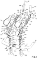
- the figures 1 and 2 show an aerodynamic assembly for a bicycle handlebar 1, respectively in exploded view and in the mounted position.
- the bicycle hanger 1 conventionally comprises a transverse bar 2, the central part of which is attached to the bicycle, generally using a stem.
- the crossbar 2 is extended by a grip zone or handle 3a, 3b at each of its two ends. These handles extend towards the front of the bicycle, substantially in the longitudinal direction of the bicycle shown in the figure by the longitudinal axis XX '.
- the indices "a” used in the reference signs to the figures are representative of the parts intended to be located to the left with respect to the longitudinal axis XX ', and the indices "b” used in the reference signs in the figures are representative of the parts intended to be located to the right with respect to the longitudinal axis XX '.
- the aerodynamic assembly features, as particularly visible on the figure 2 , two separate extension devices, namely a first left extension device 4a and a second right extension device 4b.
- each of the two extension devices left 4a and right 4b comprises a first part 5a, 5b forming an arm rest, able to be fixed on the crossbar 2 of the handlebar 1 of the bicycle extending longitudinally towards the before.
- Each first part 5a, 5b comprises a longitudinal extension 6a, 6b forming a free end portion before assembly (see figure 1 ).
- the upper surface of the first part 5a, 5b with its longitudinal extension 6a, 6b forms a receiving surface for a left or right forearm part of a cyclist.
- This reception surface can be advantageously covered with a foam coating 7a, 7b, of the same shape, to provide comfort to the cyclist, preferably removable as shown in the figure. figure 1 so as to be easily changed and / or cleaned.
- Each of the two left 4a and right 4b extension devices further comprises a second part 8a, 8b forming an extension, capable of being fixed, in a removable manner and in the extension of the first part 5a, 5b, to the free end portion of extension longitudinal 6a, 6b.
- the first parts 5a, 5b forming an arm rest and the second parts 8a, 8b forming extensions are preferably made of carbon fiber.
- the second part 8a, 8b forming an extension is also able to slide longitudinally relative to the longitudinal extension 6a, 6b to allow, as detailed below, an adjustment of the distance separating a free end of the second part 8a, 8b forming extension of the first part 5a, 5b forming an arm rest.
- the second part 8a, 8b forming an extension is able to be fixed and to slide longitudinally inside the longitudinal extension 6a, 6b.
- each second part 8a, 8b forming an extension can be fixed to its associated first part 5a, 5b forming an arm rest by a system of screws and plates. More precisely, a lower plate 9a, 9b, equipped with two threaded through holes, is housed in a first hollow end of each second part 8a, 8b forming an extension, and two screws 10a, 10'a, 10b, 10'b pass through through an upper plate 11a, 11b and the longitudinal extension 6a, 6b to be screwed into the threaded through holes of the lower plate 9a, 9b.
- bores 12a, 12b regularly spaced by a distance corresponding to the distance separating the threaded through holes of the lower plate 9a, 9b are advantageously provided through the upper surface of the second part 8a, 8b forming an extension.
- Each cyclist can thus perform a first adjustment of the insertion length which is adapted to the morphology of his forearms.
- a finer length adjustment can be advantageously obtained by providing, as shown in figure 3 , that the upper plate 11a, 11b can translate longitudinally inside an oblong-shaped opening 13a, 13b extending longitudinally on the upper part of the longitudinal extension 6a, 6b.
- the upper surface of the second part 8a, 8b forming the extension is preferably substantially in the extension of the upper surface of the first part 5a, 5b. This makes it possible to longitudinally increase the reception surface for each forearm of a cyclist.
- the upper surface of the first part 5a, 5b and the upper surface of the second part 8a, 8b forming an extension are substantially flat.
- the upper surface of the first part 5a, 5b and the upper surface of the second part 8a, 8b forming an extension are concave, which makes it possible to match at best the shape of a forearm over a large part or even over its entire length, as particularly visible on the figures 4 and 5 . This results in improved comfort and perfect forearm support.
- the lower surface of the second part 8a, 8b forming the extension is preferably substantially in the extension of the lower surface of the associated longitudinal extension 6a, 6b, the lower surface of the second part 8a, 8b forming an extension and the lower surface of the longitudinal extension 6a, 6b being advantageously convex to form a top facing the wind.
- the second part 8a, 8b forming an extension and the associated longitudinal extension 6a, 6b have complementary sections, preferably substantially triangular, as particularly visible on the figure. figure 3 on zone 14 added in dotted lines.
- Such a choice of section offers the cyclist the possibility of positioning his forearms in contact over a major part of the length of the extension devices 4a, 4b and confers improved aerodynamics, as visible by the arrows in solid lines added on the figures 5, 6 and 7 which illustrate the path followed by the wind around a cyclist's forearms as the bicycle rolls.
- the ends opposite to the hanger 1 of the parts 8a, 8b forming extensions are preferably flattened, inclined inwards with respect to the vertical, and provided with a through hole 15a, 15b (see figure 1 ) allowing removable attachment of handles 16a, 16b.
- Each handle 16a, 16b is advantageously mounted to pivot so as to allow an inclination adjustment, for example by cooperation of a tightening nut 17, a support washer 18 and a tightening screw 19.
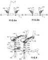
- the handles 16a, 16b have an angle ⁇ of a few degrees between their fixing lugs 20a, 20b in the lower part and the grip part.
- Each handle can thus be turned 180 ° around its axis before mounting on its fixing or, as shown on the figures 8a and 8b , invert the handles 16a, 16b. In both cases, we obtain a modification of the pinching position (inclination with respect to the vertical) of these handles.
- the flattened area of the ends opposite to the hanger 1 of the parts 8a, 8b forming extensions has an ergonomic shape 21a, 21b on which the palm of the cyclist's hand can advantageously rest (see in particular figures 1 and 2 ).
- the first part 5a, 5b forming the arm rest of each of the two extension devices 4a, 4b is configured to be fixed to the handlebar 1 of the bicycle by means of a system of adjustment, including a preferred mode, allowing a large number of adjustments (in addition to the adjustment of the sliding of the extension parts relative to the arm rest parts, and of the toe angle of the handles described above), will now be described.
- the wedges allow each cyclist to adjust the fixing height of each of the extension devices 4a, 4b relative to the crossbar 2 of the hanger 1, at the level of the first part 5a, 5b forming the arm rest.
- variable heights of 5 millimeters, 10 millimeters and 20 millimeters advantageously makes it possible to obtain heights ranging from 0 to 55 millimeters in steps of 5 millimeters, depending on the combination of shims used, providing for each set of right and left shims two 5 mm shims, two 10 mm shims, and four 20 mm shims (note that the shims are interchangeable and can be used either on the right side or on the left side).
- the view shown on the figure 9 corresponds to a height adjustment of 35 millimeters with the combined use of the three shims 25a, 26a, 27a and 25b, 26b, 27b.
- the adjustment system and therefore the associated extension devices, are able to be fixed in two dedicated zones 29a, 29b of the transverse bar 2 of the hanger 1, preferably by means of two screws 30a, 30b for clamping the supports 24a, 24b of cradles, the length of which depends on the number of wedges used for assembly, and of a support plate 31a, 31b making it possible to protect the material of the hanger 1.
- each upper plate 22a, 22b, of the cradle 23a, 23b and of the cradle support 24a, 24b to the part 5a, 5b forming the arm rest by means of the clamping screws 28a, 28b is carried out at through an oblong-shaped opening 32a, 32b extending longitudinally in the first part 5a, 5b forming an arm rest.
- Each cyclist can thus move forward or backward the parts 5a, 5b forming an arm rest along an axis transverse to the bar 2 of the hanger 1 by moving the assembly longitudinally in the oblong opening 32a, 32b before tightening the screws 28a, 28b.
- the figures 10a, 10b illustrate, in top view, two extreme positions, a first position ( figure 10a ) in which the first parts 5a, 5b are generally recessed towards the rear of the crossbar 2, and a second position ( figure 10a ) in which the first parts 5a, 5b are generally at the front of the transverse bar 2.
- a total range D max of forward / reverse translation adjustment for example equal to 55 millimeters, can thus be obtained.
- the upper plate 22a, 22b can advantageously include a cursor for locating on a graduated rule (33a on the figure 11 ), so as to help the rider in the forward / reverse translation adjustment.
- the oblong-shaped opening 32a, 32b extends longitudinally in a housing 34a, 34b of the first part 5a, 5b forming an arm rest, this housing 34a, 34b advantageously having a size of width greater than the width of the plate upper 22a, 22b.
- the two extension devices 4a, 4b can thus pivot around the upper plates 22a, 22b which serve as stops, which allows each cyclist to adjust the toe-in angle between the two extension devices 4a, 4b (angle ⁇ on the figure 12 ), before tightening the tightening screws 28a, 28b.
- a range of -7 ° to + 7 ° around the longitudinal axis of the oblong opening 32a, 32b can by example be obtained for the toe angle ⁇ .
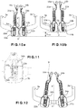
- the figure 13 is an enlarged view of the cradle support 24a of the figure 1 .
- the cradle support 24a has the general shape of an inverted capital "L", the base 35a of which is concave in shape to cooperate with the convex lower surface of the associated cradle, and is pierced with two parallel series of holes facing each other and extending. along the base of the "L" (parallel to the crossbar 2 of the hanger 1 after assembly) to form pairs accepting the clamping screws 28a.
- the cradle support 24b is of identical construction to the cradle support 24a. As visible on the figure 1 nevertheless, the cradle support 24a has its base offset to the left (with respect to the fixing points by the clamping screws 31a) while the cradle support 24b has its base offset to the right.
- the two supports 24a and 24b are advantageously interchangeable between the two extension devices 4a, 4b, so that it is possible to obtain six possible positions for fixing the first parts 5a, 5b forming an arm rest for adjustment in left translation. right.
- the housing 34a, 34b with its associated oblong-shaped opening 32a, 32b extends parallel to the longitudinal axis of the first part 5a, 5b forming an arm rest, but is also offset with respect to this longitudinal axis ( offset to the left for part 5a, and offset to the right for part 5b).
- the first two parts 5a, 5b are advantageously also interchangeable, namely that the first part 5a can be fixed to the cradle support 24a or to the cradle support 24b and the first part 5b can be fixed to the cradle support 24a or to the support Cradle 24b.
- the spacing between the centers of the parts 5a, 5b can vary between 97.5 millimeters and 205 millimeters per step depending on the distance between the holes 36a, 37a, 38a (or 36b, 37b, 38b) and the offset of each housing 34a, 34b relative to the longitudinal axis of the part 5a, 5b.
- the figures 14a illustrates, in top and rear views of the hanger, a first position of the spacing adjustment corresponding to a small spacing.
- This separation position is obtained on the one hand by combining the cradle support 24b with offset to the right with the first part 5a forming an arm rest and by fixing this combination on the left on the transverse bar 2 with the pair of holes 37b , 37'b (only the hole 37b is referenced so as not to overload the figure), and on the other hand by combining the cradle support 24a with offset to the left with the first part 5b forming an arm rest and by fixing this combination on the right on the crossbar 2 with the pair of holes 37a, 37'a (only the hole 37a is referenced so as not to overload the figure).
- the figures 14b illustrates, in top and rear views of the hanger, another position of the spacing adjustment corresponding to a maximum spacing.
- This maximum separation position is obtained on the one hand by combining the cradle support 24a with offset to the left with the first part 5b forming an arm rest and by fixing this combination on the left on the transverse bar 2 with the pair of holes 36a, 36'a (only the hole 36a is referenced so as not to overload the figure), and on the other hand by combining the cradle support 24b with offset to the right with the first part 5a forming an arm rest and by fixing this combination on the right on the crossbar 2 with the pair of holes 36b, 36'b (only the hole 36b is referenced so as not to overload the figure).
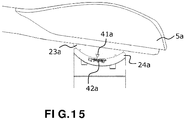
- the adjustment system also advantageously allows an inclination adjustment of each first part 5a, 5b forming arm rest by rotation about an axis substantially parallel to the longitudinal axis of the transverse bar 2.
- this adjustment of the angle of support of the forearms is made possible by the cooperation of the convex lower surface of the cradle 23a on the upper surface of the base 35a of the cradle support 24a.
- a mark 41a on the cradle 23a opposite a graduated marking 42a on the cradle support 24a advantageously makes it possible to help the cyclist in this adjustment of the angle of support of the forearms.
- the tilt angle can vary over a range of 0 ° to 12 °.
- a fixing system comprising a fixing ring which is clipped onto the transverse bar of a hanger can make it possible to adjust both the spacing of the extension devices along the bar and the bearing angle of the forearm.
Landscapes
- Engineering & Computer Science (AREA)
- Mechanical Engineering (AREA)
- Steering Devices For Bicycles And Motorcycles (AREA)
- Footwear And Its Accessory, Manufacturing Method And Apparatuses (AREA)
Claims (18)
- Aerodynamische Anordnung für Fahrradlenker, wobei die Anordnung zwei verschiedene Verlängerungsvorrichtungen (4a, 4b) aufweist, die eine erste linke Verlängerungsvorrichtung (4a) und eine zweite rechte Verlängerungsvorrichtung (4b) bilden, dadurch gekennzeichnet, dass jede der zwei Verlängerungsvorrichtungen (4a, 4b) umfasst:- einen ersten, eine Armauflage bildenden Teil (5a, 5b), der imstande ist, auf einer Querstrebe (2) eines Fahrradlenkers (1) befestigt zu sein, indem er sich längs nach vorn erstreckt und der eine Längserstreckung (6a, 6b) aufweist, die einen freien Endabschnitt bildet, wobei eine obere Fläche des ersten Teils (5a, 5b) mit seiner Längserstreckung (6a, 6b) eine Empfangsfläche für einen Teil eines Unterarms eines Radfahrers bildet; und- einen zweiten, einen Verlängerer bildenden Teil (8a, 8b), der imstande ist, lösbar und in der Verlängerung des ersten Teils (5a, 5b) am freien Endabschnitt befestigt zu sein, wobei der zweite, einen Verlängerer bildenden Teil (8a, 8b) imstande ist, längs relativ zu der Längserstreckung (6a, 6b) zu gleiten, um eine Einstellung eines Abstands zu erlauben, der ein freies Ende des zweiten, einen Verlängerer bildenden Teils (8a, 8b) vom ersten, eine Armauflage bildenden Teil (5a, 5b) trennt.
- Aerodynamische Anordnung nach Anspruch 1, dadurch gekennzeichnet, dass für jede der zwei Verlängerungsvorrichtungen (4a, 4b) eine obere Fläche des zweiten, einen Verlängerer bildenden Teils (8a, 8b) etwa in der Verlängerung der oberen Fläche des ersten Teils (5a, 5b) ist, so dass die Empfangsfläche für jeden Unterarm eines Radfahrers längs vergrößert wird.
- Aerodynamische Anordnung nach Anspruch 2, dadurch gekennzeichnet, dass für jede der zwei Verlängerungsvorrichtungen (4a, 4b) die obere Fläche des ersten Teils (5a, 5b) und die obere Fläche des zweiten, einen Verlängerer bildenden Teils (8a, 8b) etwa eben sind.
- Aerodynamische Anordnung nach Anspruch 2, dadurch gekennzeichnet, dass für jede der zwei Verlängerungsvorrichtungen (4a, 4b) die obere Fläche des ersten Teils (5a, 5b) und die obere Fläche des zweiten, einen Verlängerer bildenden Teils (8a, 8b) konkav sind, um sich an die Form eines Unterarms anzuschmiegen.
- Aerodynamische Anordnung nach einem der vorangehenden Ansprüche, dadurch gekennzeichnet, dass für jede der zwei Verlängerungsvorrichtungen (4a, 4b) eine untere Fläche des zweiten, einen Verlängerer bildenden Teils (8a, 8b) etwa in der Verlängerung einer unteren Fläche der Längserstreckung (6a, 6b) ist und dass die untere Fläche des zweiten, einen Verlängerer bildenden Teils (8a, 8b) und die untere Fläche der Längserstreckung (6a, 6b) konvex sind.
- Aerodynamische Anordnung nach einem der vorangehenden Ansprüche, dadurch gekennzeichnet, dass für jede der zwei Verlängerungsvorrichtungen (4a, 4b) der zweite, einen Verlängerer bildenden Teil (8a, 8b) und die Längserstreckung (6a, 6b) komplementäre Querschnitte haben.
- Aerodynamische Anordnung nach Anspruch 6, dadurch gekennzeichnet, dass für jede der zwei Verlängerungsvorrichtungen (4a, 4b) die komplementären Querschnitte (14) etwa dreieckig sind.
- Aerodynamische Anordnung nach einem der vorangehenden Ansprüche, dadurch gekennzeichnet, dass für jede der zwei Verlängerungsvorrichtungen (4a, 4b) der zweite, einen Verlängerer bildenden Teil (8a, 8b) imstande ist, längs innen in der Längserstreckung (6a, 6b) befestigt zu sein und zu gleiten.
- Aerodynamische Anordnung nach einem der Ansprüche 1 bis 7, dadurch gekennzeichnet, dass für jede der zwei Verlängerungsvorrichtungen der zweite, einen Verlängerer bildende Teil imstande ist, längs außen auf der Längserstreckung befestigt zu sein und zu gleiten.
- Aerodynamische Anordnung nach einem der vorangehenden Ansprüche, dadurch gekennzeichnet, dass für jede der zwei Verlängerungsvorrichtungen (4a, 4b) der erste, eine Armauflage bildende Teil (5a, 5b) ausgelegt ist, um auf einem Fahrradlenker (1) mittels eines Einstellsystems befestigt zu sein.
- Aerodynamische Anordnung nach Anspruch 10, dadurch gekennzeichnet, dass jedes Einstellsystem imstande ist, mindestens eine Einstellung von den folgenden Einstellungen durchzuführen:- eine Einstellung durch Verschieben nach oben/unten, die eine Anpassung der Höhe jedes ersten, eine Armauflage bildenden Teils (5a, 5b) in Bezug auf die Querstrebe (2) des Lenkers (1) erlaubt;- eine Einstellung durch Verschieben nach vorn/hinten, die eine Anpassung jedes ersten, eine Armauflage bildenden Teils (5a, 5b) mehr oder weniger hinter oder vor der Querstrebe (2) des Lenkers (1) erlaubt;- eine Einstellung durch Verschieben nach links/rechts, die eine Anpassung der Beabstandung der ersten, eine Armauflage bildenden Teile (5a, 5b) entlang der Querstrebe (2) des Lenkers (1) erlaubt;- eine Einstellung durch Rotieren in einer horizontalen Ebene, die die Anpassung eines Klemmwinkels zwischen den zwei Verlängerungsvorrichtungen (4a, 4b) erlaubt;- eine Einstellung durch Rotieren, die die Anpassung eines Abstützwinkels der Unterarme in Bezug auf die Horizontale erlaubt.
- Aerodynamische Anordnung nach einem der vorangehenden Ansprüche, dadurch gekennzeichnet, dass jede der zwei Verlängerungsvorrichtungen (4a, 4b) eine Verkleidung (7a, 7b) aus Schaumstoff aufweist, die imstande ist, die Empfangsfläche lösbar zu bedecken.
- Aerodynamische Anordnung nach einem der vorangehenden Ansprüche, dadurch gekennzeichnet, dass für jede der zwei Verlängerungsvorrichtungen (4a, 4b) ein Ende des zweiten, einen Verlängerer bildenden Teils (8a, 8b) abgeflacht ist und eine ergonomische Form (21a, 21b) aufweist, auf der sich ein Handteller eines Radfahrers abstützen kann.
- Aerodynamische Anordnung nach Anspruch 13, dadurch gekennzeichnet, dass jedes abgeflachte Ende mit einem Durchgangsloch (15a, 15b) ausgestattet ist, das die lösbare Befestigung eines Griffs (16a, 16b) erlaubt.
- Aerodynamische Anordnung nach Anspruch 14, dadurch gekennzeichnet, dass jeder Griff (16a, 16b) schwenkbar angebracht ist.
- Aerodynamische Anordnung nach einem der Ansprüche 13 oder 14, dadurch gekennzeichnet, dass jeder Griff (16a, 16b) einen Teil zum Ergreifen mit der Hand und Befestigungsfüße im unteren Teil aufweist, wobei der Teil zum Ergreifen mit der Hand mit den Befestigungsfüßen einen Winkel bildet.
- Aerodynamische Anordnung nach Anspruch 16, dadurch gekennzeichnet, dass die Griffe (16a, 16b) untereinander austauschbar sind, um einen Klemmwinkel zwischen diesen Griffen anzupassen.
- Fahrradlenker (1), dadurch gekennzeichnet, dass er zwei Verlängerungsvorrichtungen einer aerodynamischen Anordnung nach einem der vorangehenden Ansprüche aufweist.
Applications Claiming Priority (1)
| Application Number | Priority Date | Filing Date | Title |
|---|---|---|---|
| FR1853217A FR3080085B1 (fr) | 2018-04-12 | 2018-04-12 | Assemblage aerodynamique pour cintre de velo |
Publications (2)
| Publication Number | Publication Date |
|---|---|
| EP3552939A1 EP3552939A1 (de) | 2019-10-16 |
| EP3552939B1 true EP3552939B1 (de) | 2020-11-04 |
Family
ID=62597732
Family Applications (1)
| Application Number | Title | Priority Date | Filing Date |
|---|---|---|---|
| EP19164906.0A Active EP3552939B1 (de) | 2018-04-12 | 2019-03-25 | Aerodanymische anordnung für fahrradlenker |
Country Status (6)
| Country | Link |
|---|---|
| US (1) | US11235835B2 (de) |
| EP (1) | EP3552939B1 (de) |
| CN (1) | CN110371230B (de) |
| ES (1) | ES2837536T3 (de) |
| FR (1) | FR3080085B1 (de) |
| TW (1) | TWI779184B (de) |
Families Citing this family (9)
| Publication number | Priority date | Publication date | Assignee | Title |
|---|---|---|---|---|
| FR3080085B1 (fr) * | 2018-04-12 | 2020-03-20 | Look Cycle International | Assemblage aerodynamique pour cintre de velo |
| US11097762B1 (en) * | 2019-07-25 | 2021-08-24 | Ashley Collins | Handle extension for stroller |
| IT202000016621A1 (it) * | 2020-07-09 | 2022-01-09 | Ursus S P A | Manubrio da bicicletta con appoggi ergonomici perfezionato |
| TWI781825B (zh) * | 2021-11-17 | 2022-10-21 | 參聯國際股份有限公司 | 自行車輔助把手 |
| USD1027749S1 (en) * | 2021-12-15 | 2024-05-21 | Kids Ride Shotgun Limited | Handlebar |
| CN117057028A (zh) | 2022-05-03 | 2023-11-14 | 天心工业股份有限公司 | 自行车把手客制化流程及其系统 |
| TWI891214B (zh) * | 2024-01-19 | 2025-07-21 | 天心工業股份有限公司 | 可調式延伸把結構 |
| US12337924B1 (en) * | 2024-03-26 | 2025-06-24 | Tien Hsin Industries Co., Ltd. | Structure of adjustable extension handlebar |
| DE202024102073U1 (de) | 2024-04-24 | 2024-06-04 | Tien Hsin Industries Co., Ltd. | Verstellbare Lenkerverlängerungsstruktur |
Family Cites Families (29)
| Publication number | Priority date | Publication date | Assignee | Title |
|---|---|---|---|---|
| US6928897B2 (en) * | 2001-09-28 | 2005-08-16 | Robert C. Duncan | Bicycle handlebar extension with intergral armrest |
| US7077029B2 (en) * | 2002-09-27 | 2006-07-18 | Jas. D. Easton, Inc. | Cycle handlebars and attachments with adjustable forearm pads |
| US20050044981A1 (en) * | 2003-08-29 | 2005-03-03 | Yuan-Hsin Huang | Clipping cover for the assembling of a bicycle handle accessories |
| TWM247501U (en) * | 2003-12-18 | 2004-10-21 | Ourway Engineering Co Ltd | Retaining base for auxiliary grip lever of bicycle |
| WO2005084316A2 (en) * | 2004-03-01 | 2005-09-15 | Trek Bicycle Corporation | Unitary fiber reinforced plastic aerodynamic bicycle handlebar |
| TWM266233U (en) * | 2004-05-12 | 2005-06-01 | Ourway Engineering Co Ltd | Auxiliary handle fastening seat for bicycle |
| US7698967B2 (en) * | 2004-10-29 | 2010-04-20 | Compositech, Inc. | Bicycle handlebar with removable and adjustable aerobar |
| US7788992B2 (en) * | 2005-03-01 | 2010-09-07 | Trek Bicycle Corporation | Unitary fiber reinforced plastic aerodynamic bicycle handlebar with selectable stem |
| US7213485B2 (en) * | 2005-04-06 | 2007-05-08 | Yuan-Hsin Huang | Bicycle assistive handlebar structure |
| WO2007104943A2 (en) * | 2006-03-10 | 2007-09-20 | Ultimate Sports Engineering Limited | Bicycle handlebar |
| EP2030884B1 (de) * | 2007-08-30 | 2018-03-28 | Compositech, Inc. | Aerolenkeranordnung |
| TWM334813U (en) * | 2008-01-14 | 2008-06-21 | J D Components Co Ltd | Auxiliary handlebar with adjustable holding angle |
| CN201186718Y (zh) * | 2008-01-28 | 2009-01-28 | 参联国际贸易有限公司 | 自行车辅助把手固定座 |
| US7908940B2 (en) * | 2008-03-24 | 2011-03-22 | Shimano Inc. | Bar end electric shifter |
| US20100326232A1 (en) | 2009-06-24 | 2010-12-30 | Ming-Jen Wang | Supplemental set of handlebars for bicycle |
| US8172247B2 (en) | 2010-07-02 | 2012-05-08 | Trek Bicycle Corporation | Bicycle aero handlebar assembly |
| TWM397943U (en) * | 2010-09-23 | 2011-02-11 | Shieny Co Ltd | Bicycle handle bar and auxiliary handle bar and assembling fixture for a seat cushion |
| TW201228874A (en) * | 2011-01-07 | 2012-07-16 | Chang-Hui Lin | Anadjustablehandletheflying wing |
| US8307736B2 (en) * | 2011-03-22 | 2012-11-13 | Chang Hui Lin | Adjustable bicycle handlebar |
| TWM420474U (en) * | 2011-08-12 | 2012-01-11 | Sienna Group Corp | Invisible fastening device for auxiliary handlebars of bicycle |
| US8359713B1 (en) * | 2011-11-17 | 2013-01-29 | Sienna Group Corporation | Bike auxiliary handle fixing structure |
| TWM460041U (zh) * | 2013-03-05 | 2013-08-21 | Wei Hau Accessories Co Ltd | 自行車用之輔助把手構造 |
| DE202013004765U1 (de) * | 2013-05-22 | 2013-06-04 | Jochen Klieber | Aerolenker |
| US8850923B1 (en) * | 2013-06-11 | 2014-10-07 | Blktec Inc. | Bicycle handlebar assembly |
| US9725129B2 (en) * | 2014-12-23 | 2017-08-08 | Aerocat LLC | Streamlined aerobar for bicycle |
| US9415825B1 (en) * | 2015-03-31 | 2016-08-16 | Nicholas M Salazar | Combination bicycle handlebar and stem assembly |
| TWM545733U (zh) * | 2017-01-11 | 2017-07-21 | 天心工業股份有限公司 | 自行車之輔助操控裝置 |
| US10160510B1 (en) * | 2017-09-19 | 2018-12-25 | Nicholas M Salazar | Height and tilt adjustable handlebar and stem assembly |
| FR3080085B1 (fr) * | 2018-04-12 | 2020-03-20 | Look Cycle International | Assemblage aerodynamique pour cintre de velo |
-
2018
- 2018-04-12 FR FR1853217A patent/FR3080085B1/fr not_active Expired - Fee Related
-
2019
- 2019-03-25 ES ES19164906T patent/ES2837536T3/es active Active
- 2019-03-25 EP EP19164906.0A patent/EP3552939B1/de active Active
- 2019-04-01 TW TW108111510A patent/TWI779184B/zh active
- 2019-04-09 US US16/379,092 patent/US11235835B2/en active Active
- 2019-04-12 CN CN201910295220.4A patent/CN110371230B/zh active Active
Non-Patent Citations (1)
| Title |
|---|
| None * |
Also Published As
| Publication number | Publication date |
|---|---|
| CN110371230B (zh) | 2022-09-13 |
| TW201943592A (zh) | 2019-11-16 |
| TWI779184B (zh) | 2022-10-01 |
| FR3080085B1 (fr) | 2020-03-20 |
| EP3552939A1 (de) | 2019-10-16 |
| ES2837536T3 (es) | 2021-06-30 |
| FR3080085A1 (fr) | 2019-10-18 |
| US11235835B2 (en) | 2022-02-01 |
| US20200102046A1 (en) | 2020-04-02 |
| CN110371230A (zh) | 2019-10-25 |
Similar Documents
| Publication | Publication Date | Title |
|---|---|---|
| EP3552939B1 (de) | Aerodanymische anordnung für fahrradlenker | |
| EP0058438A2 (de) | Fahrradpedal zur Befestigung von einem Schuh in vorgesetzter Stellung und Fahrradschuh, angepasst an dieses Pedal | |
| EP2091778B1 (de) | Kopfstütze für autositz und mit dieser kopfstütze ausgestatteter autositz | |
| EP1544035A1 (de) | Vorderer Karosserieaufbau eines Kraftfahrzeuges mit verbesserten Befestigungs- und Lagejustiermitteln, und Kraftfahrzeug ausgestattet mit einem solchen Aufbau | |
| EP1563876B1 (de) | Langlaufski | |
| FR2719748A1 (fr) | Dispositif de fixation occipitale d'un casque. | |
| EP4011693B1 (de) | Rückenlehne eines fahrzeugsitzes | |
| FR2814962A1 (fr) | Perfectionnement pour dispositif de retenue d'une chaussure sur une planche de glisse sur neige du type surf | |
| EP0120758B1 (de) | Pedal-und befestigungsvorrichtung für Fahrradpedal | |
| EP1634800B1 (de) | Fronteinheit für ein Kraftfahrzeug | |
| EP1623879B1 (de) | Kraftfahrzeugfrontendmodul | |
| EP1549542B1 (de) | Glied zur befestigung einer fahrradantriebsvorrichtung | |
| FR2561502A1 (fr) | Dispositif de fixation d'une chaussure sur une pedale et parties constitutives dudit dispositif | |
| EP0367665A1 (de) | Handvorrichtung zur Verstellung eines Sicherheitsgurtels | |
| FR3018260A1 (fr) | Ensemble d'elements permettant de constituer une trottinette pour enfants | |
| FR2970935A1 (fr) | Vehicule du type bicyclette ou motocyclette comportant un cadre articule et suspendu a positionnement reglable | |
| FR2947511A1 (fr) | Engin de glisse sur neige guide par un utilisateur et comportant un passager | |
| FR3107696A3 (fr) | « Selle de vélo à surface d’appui d’ischions » | |
| FR2802171A1 (fr) | Dispositif de reglage de la position de la selle d'un deux-roues, en particulier d'une bicyclette | |
| EP4065454B1 (de) | Sitz, insbesondere geeignet für ein fahrrad | |
| FR3036365A1 (fr) | Selle a dossier reglable longitudinalement et en hauteur pour vehicule motorise etroit | |
| FR2948625A1 (fr) | Velocipede a selle reglable | |
| FR3148000A1 (fr) | Systeme de verrouillage en position pliee pour velo pliant | |
| FR2829442A1 (fr) | Appui-tete convertible, notamment pour vehicule automobile | |
| EP3344204B1 (de) | Sichtschtutzzubehör mit vorrichtung zur beabstandung des bildschirms vom rahmen |
Legal Events
| Date | Code | Title | Description |
|---|---|---|---|
| PUAI | Public reference made under article 153(3) epc to a published international application that has entered the european phase |
Free format text: ORIGINAL CODE: 0009012 |
|
| STAA | Information on the status of an ep patent application or granted ep patent |
Free format text: STATUS: THE APPLICATION HAS BEEN PUBLISHED |
|
| AK | Designated contracting states |
Kind code of ref document: A1 Designated state(s): AL AT BE BG CH CY CZ DE DK EE ES FI FR GB GR HR HU IE IS IT LI LT LU LV MC MK MT NL NO PL PT RO RS SE SI SK SM TR |
|
| AX | Request for extension of the european patent |
Extension state: BA ME |
|
| STAA | Information on the status of an ep patent application or granted ep patent |
Free format text: STATUS: REQUEST FOR EXAMINATION WAS MADE |
|
| 17P | Request for examination filed |
Effective date: 20191115 |
|
| RBV | Designated contracting states (corrected) |
Designated state(s): AL AT BE BG CH CY CZ DE DK EE ES FI FR GB GR HR HU IE IS IT LI LT LU LV MC MK MT NL NO PL PT RO RS SE SI SK SM TR |
|
| GRAP | Despatch of communication of intention to grant a patent |
Free format text: ORIGINAL CODE: EPIDOSNIGR1 |
|
| STAA | Information on the status of an ep patent application or granted ep patent |
Free format text: STATUS: GRANT OF PATENT IS INTENDED |
|
| INTG | Intention to grant announced |
Effective date: 20200422 |
|
| GRAJ | Information related to disapproval of communication of intention to grant by the applicant or resumption of examination proceedings by the epo deleted |
Free format text: ORIGINAL CODE: EPIDOSDIGR1 |
|
| STAA | Information on the status of an ep patent application or granted ep patent |
Free format text: STATUS: REQUEST FOR EXAMINATION WAS MADE |
|
| GRAP | Despatch of communication of intention to grant a patent |
Free format text: ORIGINAL CODE: EPIDOSNIGR1 |
|
| STAA | Information on the status of an ep patent application or granted ep patent |
Free format text: STATUS: GRANT OF PATENT IS INTENDED |
|
| INTC | Intention to grant announced (deleted) | ||
| INTG | Intention to grant announced |
Effective date: 20200812 |
|
| GRAS | Grant fee paid |
Free format text: ORIGINAL CODE: EPIDOSNIGR3 |
|
| GRAA | (expected) grant |
Free format text: ORIGINAL CODE: 0009210 |
|
| STAA | Information on the status of an ep patent application or granted ep patent |
Free format text: STATUS: THE PATENT HAS BEEN GRANTED |
|
| AK | Designated contracting states |
Kind code of ref document: B1 Designated state(s): AL AT BE BG CH CY CZ DE DK EE ES FI FR GB GR HR HU IE IS IT LI LT LU LV MC MK MT NL NO PL PT RO RS SE SI SK SM TR |
|
| REG | Reference to a national code |
Ref country code: GB Ref legal event code: FG4D Free format text: NOT ENGLISH |
|
| REG | Reference to a national code |
Ref country code: CH Ref legal event code: EP |
|
| REG | Reference to a national code |
Ref country code: AT Ref legal event code: REF Ref document number: 1330488 Country of ref document: AT Kind code of ref document: T Effective date: 20201115 |
|
| REG | Reference to a national code |
Ref country code: IE Ref legal event code: FG4D Free format text: LANGUAGE OF EP DOCUMENT: FRENCH |
|
| REG | Reference to a national code |
Ref country code: DE Ref legal event code: R096 Ref document number: 602019001165 Country of ref document: DE |
|
| REG | Reference to a national code |
Ref country code: NL Ref legal event code: FP |
|
| REG | Reference to a national code |
Ref country code: AT Ref legal event code: MK05 Ref document number: 1330488 Country of ref document: AT Kind code of ref document: T Effective date: 20201104 |
|
| PG25 | Lapsed in a contracting state [announced via postgrant information from national office to epo] |
Ref country code: NO Free format text: LAPSE BECAUSE OF FAILURE TO SUBMIT A TRANSLATION OF THE DESCRIPTION OR TO PAY THE FEE WITHIN THE PRESCRIBED TIME-LIMIT Effective date: 20210204 Ref country code: GR Free format text: LAPSE BECAUSE OF FAILURE TO SUBMIT A TRANSLATION OF THE DESCRIPTION OR TO PAY THE FEE WITHIN THE PRESCRIBED TIME-LIMIT Effective date: 20210205 Ref country code: RS Free format text: LAPSE BECAUSE OF FAILURE TO SUBMIT A TRANSLATION OF THE DESCRIPTION OR TO PAY THE FEE WITHIN THE PRESCRIBED TIME-LIMIT Effective date: 20201104 Ref country code: PT Free format text: LAPSE BECAUSE OF FAILURE TO SUBMIT A TRANSLATION OF THE DESCRIPTION OR TO PAY THE FEE WITHIN THE PRESCRIBED TIME-LIMIT Effective date: 20210304 Ref country code: FI Free format text: LAPSE BECAUSE OF FAILURE TO SUBMIT A TRANSLATION OF THE DESCRIPTION OR TO PAY THE FEE WITHIN THE PRESCRIBED TIME-LIMIT Effective date: 20201104 |
|
| PG25 | Lapsed in a contracting state [announced via postgrant information from national office to epo] |
Ref country code: BG Free format text: LAPSE BECAUSE OF FAILURE TO SUBMIT A TRANSLATION OF THE DESCRIPTION OR TO PAY THE FEE WITHIN THE PRESCRIBED TIME-LIMIT Effective date: 20210204 Ref country code: SE Free format text: LAPSE BECAUSE OF FAILURE TO SUBMIT A TRANSLATION OF THE DESCRIPTION OR TO PAY THE FEE WITHIN THE PRESCRIBED TIME-LIMIT Effective date: 20201104 Ref country code: IS Free format text: LAPSE BECAUSE OF FAILURE TO SUBMIT A TRANSLATION OF THE DESCRIPTION OR TO PAY THE FEE WITHIN THE PRESCRIBED TIME-LIMIT Effective date: 20210304 Ref country code: PL Free format text: LAPSE BECAUSE OF FAILURE TO SUBMIT A TRANSLATION OF THE DESCRIPTION OR TO PAY THE FEE WITHIN THE PRESCRIBED TIME-LIMIT Effective date: 20201104 Ref country code: LV Free format text: LAPSE BECAUSE OF FAILURE TO SUBMIT A TRANSLATION OF THE DESCRIPTION OR TO PAY THE FEE WITHIN THE PRESCRIBED TIME-LIMIT Effective date: 20201104 Ref country code: AT Free format text: LAPSE BECAUSE OF FAILURE TO SUBMIT A TRANSLATION OF THE DESCRIPTION OR TO PAY THE FEE WITHIN THE PRESCRIBED TIME-LIMIT Effective date: 20201104 |
|
| REG | Reference to a national code |
Ref country code: LT Ref legal event code: MG9D |
|
| PG25 | Lapsed in a contracting state [announced via postgrant information from national office to epo] |
Ref country code: HR Free format text: LAPSE BECAUSE OF FAILURE TO SUBMIT A TRANSLATION OF THE DESCRIPTION OR TO PAY THE FEE WITHIN THE PRESCRIBED TIME-LIMIT Effective date: 20201104 |
|
| REG | Reference to a national code |
Ref country code: ES Ref legal event code: FG2A Ref document number: 2837536 Country of ref document: ES Kind code of ref document: T3 Effective date: 20210630 |
|
| PG25 | Lapsed in a contracting state [announced via postgrant information from national office to epo] |
Ref country code: RO Free format text: LAPSE BECAUSE OF FAILURE TO SUBMIT A TRANSLATION OF THE DESCRIPTION OR TO PAY THE FEE WITHIN THE PRESCRIBED TIME-LIMIT Effective date: 20201104 Ref country code: LT Free format text: LAPSE BECAUSE OF FAILURE TO SUBMIT A TRANSLATION OF THE DESCRIPTION OR TO PAY THE FEE WITHIN THE PRESCRIBED TIME-LIMIT Effective date: 20201104 Ref country code: CZ Free format text: LAPSE BECAUSE OF FAILURE TO SUBMIT A TRANSLATION OF THE DESCRIPTION OR TO PAY THE FEE WITHIN THE PRESCRIBED TIME-LIMIT Effective date: 20201104 Ref country code: EE Free format text: LAPSE BECAUSE OF FAILURE TO SUBMIT A TRANSLATION OF THE DESCRIPTION OR TO PAY THE FEE WITHIN THE PRESCRIBED TIME-LIMIT Effective date: 20201104 Ref country code: SM Free format text: LAPSE BECAUSE OF FAILURE TO SUBMIT A TRANSLATION OF THE DESCRIPTION OR TO PAY THE FEE WITHIN THE PRESCRIBED TIME-LIMIT Effective date: 20201104 Ref country code: SK Free format text: LAPSE BECAUSE OF FAILURE TO SUBMIT A TRANSLATION OF THE DESCRIPTION OR TO PAY THE FEE WITHIN THE PRESCRIBED TIME-LIMIT Effective date: 20201104 |
|
| REG | Reference to a national code |
Ref country code: DE Ref legal event code: R097 Ref document number: 602019001165 Country of ref document: DE |
|
| PG25 | Lapsed in a contracting state [announced via postgrant information from national office to epo] |
Ref country code: DK Free format text: LAPSE BECAUSE OF FAILURE TO SUBMIT A TRANSLATION OF THE DESCRIPTION OR TO PAY THE FEE WITHIN THE PRESCRIBED TIME-LIMIT Effective date: 20201104 |
|
| PLBE | No opposition filed within time limit |
Free format text: ORIGINAL CODE: 0009261 |
|
| STAA | Information on the status of an ep patent application or granted ep patent |
Free format text: STATUS: NO OPPOSITION FILED WITHIN TIME LIMIT |
|
| 26N | No opposition filed |
Effective date: 20210805 |
|
| PG25 | Lapsed in a contracting state [announced via postgrant information from national office to epo] |
Ref country code: AL Free format text: LAPSE BECAUSE OF FAILURE TO SUBMIT A TRANSLATION OF THE DESCRIPTION OR TO PAY THE FEE WITHIN THE PRESCRIBED TIME-LIMIT Effective date: 20201104 Ref country code: MC Free format text: LAPSE BECAUSE OF FAILURE TO SUBMIT A TRANSLATION OF THE DESCRIPTION OR TO PAY THE FEE WITHIN THE PRESCRIBED TIME-LIMIT Effective date: 20201104 |
|
| PG25 | Lapsed in a contracting state [announced via postgrant information from national office to epo] |
Ref country code: SI Free format text: LAPSE BECAUSE OF FAILURE TO SUBMIT A TRANSLATION OF THE DESCRIPTION OR TO PAY THE FEE WITHIN THE PRESCRIBED TIME-LIMIT Effective date: 20201104 |
|
| PG25 | Lapsed in a contracting state [announced via postgrant information from national office to epo] |
Ref country code: LU Free format text: LAPSE BECAUSE OF NON-PAYMENT OF DUE FEES Effective date: 20210325 Ref country code: IE Free format text: LAPSE BECAUSE OF NON-PAYMENT OF DUE FEES Effective date: 20210325 |
|
| PG25 | Lapsed in a contracting state [announced via postgrant information from national office to epo] |
Ref country code: IS Free format text: LAPSE BECAUSE OF FAILURE TO SUBMIT A TRANSLATION OF THE DESCRIPTION OR TO PAY THE FEE WITHIN THE PRESCRIBED TIME-LIMIT Effective date: 20210304 |
|
| REG | Reference to a national code |
Ref country code: CH Ref legal event code: PL |
|
| PG25 | Lapsed in a contracting state [announced via postgrant information from national office to epo] |
Ref country code: LI Free format text: LAPSE BECAUSE OF NON-PAYMENT OF DUE FEES Effective date: 20220331 Ref country code: CH Free format text: LAPSE BECAUSE OF NON-PAYMENT OF DUE FEES Effective date: 20220331 |
|
| PG25 | Lapsed in a contracting state [announced via postgrant information from national office to epo] |
Ref country code: CY Free format text: LAPSE BECAUSE OF FAILURE TO SUBMIT A TRANSLATION OF THE DESCRIPTION OR TO PAY THE FEE WITHIN THE PRESCRIBED TIME-LIMIT Effective date: 20201104 |
|
| PG25 | Lapsed in a contracting state [announced via postgrant information from national office to epo] |
Ref country code: HU Free format text: LAPSE BECAUSE OF FAILURE TO SUBMIT A TRANSLATION OF THE DESCRIPTION OR TO PAY THE FEE WITHIN THE PRESCRIBED TIME-LIMIT; INVALID AB INITIO Effective date: 20190325 |
|
| PGFP | Annual fee paid to national office [announced via postgrant information from national office to epo] |
Ref country code: NL Payment date: 20240320 Year of fee payment: 6 |
|
| PG25 | Lapsed in a contracting state [announced via postgrant information from national office to epo] |
Ref country code: MK Free format text: LAPSE BECAUSE OF FAILURE TO SUBMIT A TRANSLATION OF THE DESCRIPTION OR TO PAY THE FEE WITHIN THE PRESCRIBED TIME-LIMIT Effective date: 20201104 |
|
| PGFP | Annual fee paid to national office [announced via postgrant information from national office to epo] |
Ref country code: DE Payment date: 20240320 Year of fee payment: 6 Ref country code: GB Payment date: 20240320 Year of fee payment: 6 |
|
| PGFP | Annual fee paid to national office [announced via postgrant information from national office to epo] |
Ref country code: IT Payment date: 20240329 Year of fee payment: 6 Ref country code: BE Payment date: 20240320 Year of fee payment: 6 |
|
| PG25 | Lapsed in a contracting state [announced via postgrant information from national office to epo] |
Ref country code: TR Free format text: LAPSE BECAUSE OF FAILURE TO SUBMIT A TRANSLATION OF THE DESCRIPTION OR TO PAY THE FEE WITHIN THE PRESCRIBED TIME-LIMIT Effective date: 20201104 |
|
| PGFP | Annual fee paid to national office [announced via postgrant information from national office to epo] |
Ref country code: ES Payment date: 20240429 Year of fee payment: 6 |
|
| PG25 | Lapsed in a contracting state [announced via postgrant information from national office to epo] |
Ref country code: MT Free format text: LAPSE BECAUSE OF FAILURE TO SUBMIT A TRANSLATION OF THE DESCRIPTION OR TO PAY THE FEE WITHIN THE PRESCRIBED TIME-LIMIT Effective date: 20201104 |
|
| PGFP | Annual fee paid to national office [announced via postgrant information from national office to epo] |
Ref country code: FR Payment date: 20250326 Year of fee payment: 7 |
|
| REG | Reference to a national code |
Ref country code: DE Ref legal event code: R119 Ref document number: 602019001165 Country of ref document: DE |
|
| REG | Reference to a national code |
Ref country code: NL Ref legal event code: MM Effective date: 20250401 |
|
| GBPC | Gb: european patent ceased through non-payment of renewal fee |
Effective date: 20250325 |
|
| REG | Reference to a national code |
Ref country code: BE Ref legal event code: MM Effective date: 20250331 |
|
| PG25 | Lapsed in a contracting state [announced via postgrant information from national office to epo] |
Ref country code: NL Free format text: LAPSE BECAUSE OF NON-PAYMENT OF DUE FEES Effective date: 20250401 |
|
| PG25 | Lapsed in a contracting state [announced via postgrant information from national office to epo] |
Ref country code: DE Free format text: LAPSE BECAUSE OF NON-PAYMENT OF DUE FEES Effective date: 20251001 |
|
| PG25 | Lapsed in a contracting state [announced via postgrant information from national office to epo] |
Ref country code: GB Free format text: LAPSE BECAUSE OF NON-PAYMENT OF DUE FEES Effective date: 20250325 |
|
| PG25 | Lapsed in a contracting state [announced via postgrant information from national office to epo] |
Ref country code: IT Free format text: LAPSE BECAUSE OF NON-PAYMENT OF DUE FEES Effective date: 20250325 |
|
| PG25 | Lapsed in a contracting state [announced via postgrant information from national office to epo] |
Ref country code: BE Free format text: LAPSE BECAUSE OF NON-PAYMENT OF DUE FEES Effective date: 20250331 |