EP1548482A1 - Mikroskopobjektiv mit axial verstellbaren Korrekturfassungen - Google Patents
Mikroskopobjektiv mit axial verstellbaren Korrekturfassungen Download PDFInfo
- Publication number
- EP1548482A1 EP1548482A1 EP04029779A EP04029779A EP1548482A1 EP 1548482 A1 EP1548482 A1 EP 1548482A1 EP 04029779 A EP04029779 A EP 04029779A EP 04029779 A EP04029779 A EP 04029779A EP 1548482 A1 EP1548482 A1 EP 1548482A1
- Authority
- EP
- European Patent Office
- Prior art keywords
- microscope objective
- rings
- correction
- objective according
- adjusting ring
- Prior art date
- Legal status (The legal status is an assumption and is not a legal conclusion. Google has not performed a legal analysis and makes no representation as to the accuracy of the status listed.)
- Granted
Links
- 230000003287 optical effect Effects 0.000 claims abstract description 33
- 238000012937 correction Methods 0.000 claims description 46
- 230000006835 compression Effects 0.000 claims description 3
- 238000007906 compression Methods 0.000 claims description 3
- 230000002093 peripheral effect Effects 0.000 claims description 3
- 238000003384 imaging method Methods 0.000 claims 1
- 230000035515 penetration Effects 0.000 claims 1
- 238000006073 displacement reaction Methods 0.000 description 7
- 239000006059 cover glass Substances 0.000 description 6
- 230000007613 environmental effect Effects 0.000 description 3
- 238000007654 immersion Methods 0.000 description 3
- PEDCQBHIVMGVHV-UHFFFAOYSA-N Glycerine Chemical compound OCC(O)CO PEDCQBHIVMGVHV-UHFFFAOYSA-N 0.000 description 2
- 230000004075 alteration Effects 0.000 description 2
- 238000005553 drilling Methods 0.000 description 2
- 238000000386 microscopy Methods 0.000 description 2
- 230000006978 adaptation Effects 0.000 description 1
- 230000001419 dependent effect Effects 0.000 description 1
- 238000001514 detection method Methods 0.000 description 1
- 235000011187 glycerol Nutrition 0.000 description 1
- 230000003993 interaction Effects 0.000 description 1
- 239000007788 liquid Substances 0.000 description 1
- 238000010859 live-cell imaging Methods 0.000 description 1
- 238000004519 manufacturing process Methods 0.000 description 1
- 239000003550 marker Substances 0.000 description 1
- 238000003801 milling Methods 0.000 description 1
- 230000008092 positive effect Effects 0.000 description 1
- 238000002360 preparation method Methods 0.000 description 1
- 239000007787 solid Substances 0.000 description 1
- XLYOFNOQVPJJNP-UHFFFAOYSA-N water Substances O XLYOFNOQVPJJNP-UHFFFAOYSA-N 0.000 description 1
Images


Classifications
-
- G—PHYSICS
- G02—OPTICS
- G02B—OPTICAL ELEMENTS, SYSTEMS OR APPARATUS
- G02B7/00—Mountings, adjusting means, or light-tight connections, for optical elements
- G02B7/02—Mountings, adjusting means, or light-tight connections, for optical elements for lenses
- G02B7/023—Mountings, adjusting means, or light-tight connections, for optical elements for lenses permitting adjustment
-
- G—PHYSICS
- G02—OPTICS
- G02B—OPTICAL ELEMENTS, SYSTEMS OR APPARATUS
- G02B21/00—Microscopes
- G02B21/02—Objectives
Definitions
- the invention relates to a microscope objective with axially adjustable Correction frames in which lenses or lens groups are arranged, in particular for live cell imaging and for research on cell and tissue cultures.
- the Invention is related to microscope objectives in conjunction with different Cover glasses and / or different immersion liquids and / or at different operating temperatures applicable.
- DE 38 12 745 C2 is a microscope objective with a Aperture of at least 0.5 and a setup device described on different cover glass thicknesses, in which one between a fixed first lens group and a fixed third lens group one second lens group is arranged linearly displaceable, too which displaced another lens group in opposite axial direction can be.
- the movement strokes of this can shiftable lens groups be different.
- a single actuating ring is provided.
- This Lens is the device for setting to different Cover glass thicknesses with a device for refocusing coupled to the entire lens.
- the lens groups are linearly displaced during the adjustment movement. This can be different, for example, by thread Reach slope or through cams, which in corresponding grooves with constant but different Gradient in a rotatable intermediate ring of the lens frame intervention.
- An adjusting device for a lens is in DE 199 47 378 A1 described, which with an axially movable Optic member is provided, which has a sliding mount with the main version is connected.
- a first linear drive via actuators with a second linear drive, which the linear movement along the optical Axis created, connected.
- the second linear drive is with connected to the sliding mount.
- the invention is based on the object, a microscope objective to create with correction frames, with which with good correction of the aberrations and compliance a small length of the lens a setting to compensate for at least three, the image quality influencing parameters is possible.
- this object is achieved according to the preamble designed microscope lens with the distinctive Characteristics of the first claim solved.
- Adjusting rings each with at least a driving ring in operative connection, wherein Advantageously, the individual adjusting rings independently to be rotated about the optical axis of the lens can.
- compression springs or elements which the Function of a compression spring exercise, can be used.
- the bolts engage in a play formed by at least one resilient web, open to the edge of the respective associated threaded ring hole.
- the diameter of the bore is advantageously smaller than or equal to the diameter of the engaging in the bore of the threaded ring part of the respective bolt.
- a play-free connection between the bolt and the associated Threaded ring is also advantageous if between the bolt and the wall of the threaded ring bore an elastic intermediate member is provided.
- the invention serves a microscope objective in a optical correction by axial displacement of three or more optic links with the help of radially moving threaded rings with threads of equal or different Gradient, without the usual curve rings and without to use spiral grooves in individual rings, too realize.
- this lens has a short overall length achievable in the order of 50 mm. At a Small working distance of about 0.18 mm is also a reliable Preparation or object protection in a simple manner realizable.
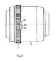
- the illustrated in Figure 1 in a partial section microscope objective includes a provided with a screw thread 1.1 Main version 1 with a fixed to this, inside cylindrical sleeve 2, which axially directed Breakthroughs 3.1 to 3.4 owns and in the precise, axial adjustable correction frames 4.1 to 4.4 arranged are.
- four correction frames are 4.1 to 4.4 provided.
- the cylinder sleeve 2 also a corresponding number of breakthroughs.
- the number of interacting with the correction frames Components depend on the number of correction frames.
- correction versions 4.1 to 4.4 are the individual optical members (not shown) firmly, which consists of individual lenses and / or lens groups consist.
- At the individual correction versions 4.1 bis 4.4 is outside each one, through an associated breakthrough 3.1 to 3.4 of the cylinder sleeve 2 reaching therethrough (gripping), radially directed bolt 6.1 to 6.4 or a screw arranged.
- Each of these bolts 6.1 to 6.4 stands with its associated threaded ring 9.1 bis 9.4 in operative connection.
- These threaded rings 9.1 to 9.4 have one external thread 8.1 to 8.4 and are only mounted axially adjustable on the cylinder sleeve 2.
- the threaded rings 9.1 to 9.4 and the driving rings 10.1 to 10.4 can thread equal or different pitch own, so that with the same rotation of the driving rings 10.1 to 10.4 about the optical axis 7 of the lens non-rotatable threaded rings 9.1 to 9.4 different shifts in the direction of the optical axis 7 run.
- the individual driving rings 10.1 to 10.4 are advantageous by screws 13.1 to 13.3 or pins connected to each other and stand with at least one, externally operated and around the optical axis 7 rotatable adjustment ring 11 in operative connection.
- the lens On the object side, the lens has an object or specimen protection Serving fuse element 14, which over an intermediate part 14.1 with the front correction frame 4.1 is connected and moved axially together with this.
- the correction versions 4.1 to 4.4 in which the optical Links (not shown) are taken and the external threads 8.1 to 8.4 bearing threaded rings 9.1 to 9.4 are connected by the bolts 6.1 to 6.4.
- These bolts 6.1 to 6.4 are due to the axial openings 3.1 to 3.4 of firmly arranged in the main frame 1 cylinder sleeve. 2 passed through and thus have together with the threaded rings 5.1 to 5.4 and the correction versions 4.1 to 4.4 only an adjustment or displacement in the direction the optical axis 7.
- a rotation about the axis 7 is not possible.
- By rotation of the adjusting ring 11 to the optical axis 7 are the interconnected driving rings 10.1 to 10.4 with rotated about the axis 7.
- Fig. 4 and Fig. 5 show the example of the threaded ring 9.1 and the bolt 6.1 as a backlash-free invention Connection between these two components is realized. Especially with high-quality microscopic lenses is such a connection to achieve a nearly error-free Illustration absolutely necessary.
- a Connection engages screwed in the correction version 4.1 and radially directed bolt 6.1 in one in axial Direction to the edge 19 towards the threaded ring 9.1 milled freely Hole 20 a.
- This bore 20 is defined by two, produced by cutouts 21 and 22 of the threaded ring 9.1, resilient webs 17; 18 formed. By the springy Webs 17 and 18 is formed in the threaded ring 9.1 a clamping of the bolt 6.1.
- the shaft of these webs 17; 18 is advantageous in their strength so dimensioned that they themselves not by the movement of the pin 6.1 and other parts of the lens can be further spread.
- the respective bolt 6.1 to 6.4 is in his assigned hole arranged without play. Another positive effect arises in the bore 20 a three-point system of the bolt 20, whereby a precise guidance in the respective threaded ring arises.
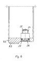
- Fig. 6 is based on the threaded ring 9.3 and the bolt 6.3 will be explained in more detail.
- the bolt 6.3 which with its threaded end 24 in the correction socket 4.3 (not shown in Fig. 6) screwed is, engages in a bore 26 of the associated, with the Thread 8.3 threaded nut 9.3 provided.
- the backlash ensuring intermediate member 27 is arranged between the Bolt 6.3 and the wall of the bore 26 .
- this intermediate member has 27 the shape of a round ring. Other suitable designs the intermediate member 27 are also possible.
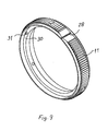
- the spatially illustrated in Fig. 7 microscope objective includes, inter alia, the main version 1 and the rotatable thereon mounted adjustment ring 11, which a mark 28 owns.
- At the main frame 1 are setting marks 29th arranged, which, for example, the adjustment of the lens to different cover glasses or to different Environmental conditions can serve.
- a axially directed pin 31 preferably in a bore is arranged at an in Interior of the adjusting ring 11 located end face 30 .
- This pin 31 is in a defined Position arranged to mark the adjustment ring 11.
- the main version 1 has in its interior at an end face 32 ( Figure 10) extends over a peripheral area extending outbreak 33, whose boundary surfaces as Stops 34; 35 for the pin 31 in the rotation of the Adjustment ring 11 relative to the main version 1.
- the limitation the breakout 33, so the attacks 34; 35 are also oriented to the mark 28 of the adjusting ring 11.
- the angle of the breakout 33 of the main frame 1 determines the width of the overflow, which is advantageous Passing the zero mark in both directions in narrow limits allowed.
- the uniformity of the overflow is automatically determined by the orientation of the outbreak 33 to the respective adjustment mark 29 of the main version 1 given. This measure will be without additional Share a uniform overflow and 7 and solid stops 34; 35 for limiting the rotation of the adjusting ring 11th achieved.
- This arrangement is applicable to all microscope objectives applicable with one or more adjusting rings, such. B. also micro-lenses with iris diaphragm.
Landscapes
- Physics & Mathematics (AREA)
- General Physics & Mathematics (AREA)
- Optics & Photonics (AREA)
- Chemical & Material Sciences (AREA)
- Analytical Chemistry (AREA)
- Microscoopes, Condenser (AREA)
- Lens Barrels (AREA)
- Lenses (AREA)
Abstract
Description
Um stets eine Klemmung des Bolzens in der Bohrung zu realisieren, ist vorteilhaft der Durchmesser der Bohrung kleiner als der oder gleich dem Durchmesser des in die Bohrung des Gewinderinges eingreifenden Teiles des jeweiligen Bolzens.
- Fig.1
- einen teilweisen Längsschnitt durch ein erfindungsgemäßes Mikroskopobjektiv,
- Fig. 2
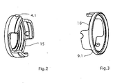
- ein weiteres Fassungsteil des vorderen optischen Gliedes,
- Fig. 3
- ein Fassungsteil des vorderen optischen Gliedes,
- Fig. 4
- einen Gewindering mit geöffneter Bohrung und federnden Stegen,
- Fig. 5
- einen Gewindering mit eingreifendem Bolzen,
- Fig. 6
- einen Gewindering mit Bolzen und elastischem Element,
- Fig. 7
- eine Ansicht eines Objektivs mit Hauptfassung und Einstellring,
- Fig. 8
- ein Objektiv mit geöffnetem Einstellring,
- Fig. 9
- einen Einstellring und
- Fig. 10
- die Hauptfassung mit Ausbruch und Skala.
- 1
- Hauptfassung
- 2
- Zylinderhülse
- 3.1 bis 3.4
- Durchbrüche
- 4.1 bis 4.4
- Korrekturfassungen
- 6.1 bis 6.4
- Bolzen
- 7
- optische Achse
- 8.1 bis 8.4
- Außengewinde
- 9.1 bis 9.4
- Gewinderinge
- 10.1 bis 10.4
- Mitnahmeringe
- 11
- Einstellring
- 12.1 bis 12.4
- Federelemente
- 13.1 bis 13.4
- Schrauben
- 14
- Sicherungselement
- 14.1
- Zwischenteil
- 15, 16
- Aussparungen
- 17, 18
- Stege
- 19
- Rand
- 20
- Bohrung
- 21; 22
- Ausfräsungen
- 23
- Zwischenglied
- 24
- Gewinde
- 25
- Ende
- 26
- Bohrung
- 27
- Zwischenglied
- 28
- Markierung
- 29
- Einstellmarke
- 30
- Stirnfläche
- 31
- Stift
- 32
- Stirnfläche
- 33
- Ausbruch
- 34; 35
- Anschläge
Claims (13)
- Mikroskopobjektiv mit axial verstellbaren Korrekturfassungen zur Anpassung an unterschiedliche, die Abbildungsgüte beeinflussende Parameter, wobei die axiale Verstellung der Korrekturfassungen relativ zu einer feststehenden Hauptfassung von einem außen an der Hauptfassung angeordneten Einstellring über einen in der jeweiligen Korrekturfassung angeordneten, radial zur optischen Achse des Objektivs gerichteten, in Durchbrüchen von Gewinderingen eingreifenden Zapfen realisierbar ist, dadurch gekennzeichnet, daß das Objektiv mindestens drei Korrekturfassungen (4.1 bis 4.4) umfaßt, welche durch mindestens einen Einstellring (11) ohne eine zusätzliche Drehung um die optische Achse (7) des Objektivs in Richtung dieser Achse (7) verstellbar sind.
- Mikroskopobjektiv nach Anspruch 1, umfassend
eine Hauptfassung (1), die mit einer innen liegenden Zylinderhülse (2) mit axial gerichteten Durchbrüchen (3.1 bis 3.4) fest verbunden ist,
axial verstellbare Korrekturfassungen (4.1 bis 4.4) zur Aufnahme optischer Glieder, welche in der Zylinderhülse (2) axial verschiebbar gelagert sind und an denen außen jeweils ein, durch einen zugeordneten Durchbruch (3.1 bis 3.4) der Zylinderhülse (2) hindurch reichender, radial gerichteter Bolzen (6.1 bis 6.4) oder Schraube angeordnet ist, wobei
mit jeweils einem Bolzen (6.1 bis 6.4) in Wirkverbindung stehende, mit einem Außengewinde (8.1 bis 8.4) gleicher oder unterschiedlicher Steigung versehene Gewinderinge (9.1 bis 9.4), welche nur axial verschiebbar auf der Zylinderhülse (2) gelagert sind und in ein Innengewinde entsprechender Steigung von jeweils den Gewinderingen (9.1 bis 9.4) zugeordneten Mitnahmeringen (10.1 bis 10.4) eingreifen, die um die optische Achse (7) drehbar in der Hauptfassung (1) angeordnet sind und mit mindestens einem außen an der Hauptfassung (1) angeordneten Einstellring (11) in Wirkverbindung stehen und mit diesem gedreht werden können. - Mikroskopobjektiv nach Anspruch 2, dadurch gekennzeichnet, daß die mit einem Einstellring (11) in Wirkverbindung stehenden Mitnahmeringe (10.1 bis 10.4) fest miteinander verbunden und gemeinsam durch den Einstellring (11) um die optische Achse (7) drehbar sind.
- Mikroskopobjektiv nach einem der Ansprüche 1 bis 3, dadurch gekennzeichnet, daß mehrere Einstellringe (11) vorgesehen sind, welche jeweils mit mindestens einem Mitnahmering (10.1 bis 10.4) in Wirkverbindung stehen.
- Mikroskopobjektiv nach einem der Ansprüche 1 bis 4, dadurch gekennzeichnet, daß die einem Einstellring (11) zugeordneten Mitnahmeringe (10.1 bis 10.4) Gewinde gleicher oder unterschiedlicher Steigung aufweisen.
- Mikroskopobjektiv nach einem der Ansprüche 1 bis 5, dadurch gekennzeichnet, daß zur Beseitigung des Spiels oder des toten Ganges im Gewinde zwischen den Mitnahmeringen (10.1 bis 10.4) und den zugeordneten Gewinderingen (9.1 bis 9.4) Federelemente (12.1 bis 12.4) angeordnet sind.
- Mikroskopobjektiv nach Anspruch 6, dadurch gekennzeichnet, daß die Federelemente (12.1 bis 12.4) Druckfedern sind.
- Mikroskopobjektiv nach einem der Ansprüche 1 bis 7, dadurch gekennzeichnet, daß mit der vorderen Korrekturfassung (4.1) ein dem Schutz des Objektes dienendes Sicherheitselement (14) verbunden ist, welches mit der Korrekturfassung (4.1) zusammen axial bewegbar ist.
- Mikroskopobjektiv nach einem der Ansprüche 1 bis 8, dadurch gekennzeichnet, daß die Bolzen (6.1 bis 6.4) in eine durch mindestens einen federnden Steg (17 oder 18) gebildete, zum Rand (19) des jeweils zugeordneten Gewinderinges (9.1 bis 9.4) offene Bohrung (20) spielfrei eingreifen.
- Mikroskopobjektiv nach Anspruch 9, dadurch gekennzeichnet, daß der Durchmesser der Bohrung (20) kleiner als der oder gleich dem Durchmesser des in die Bohrung (20) eingreifenden Teiles des jeweiligen Bolzens (6.1 bis 6.4) ist.
- Mikroskopobjektiv nach Anspruch 9, dadurch gekennzeichnet, daß zwischen dem Bolzen (6.1 bis 6.4) und der zugehörigen Bohrung (20) des jeweiligen Gewinderinges (9.1 bis 9.4) ein elastisches Zwischenglied (23) vorgesehen ist.
- Mikroskopobjektiv nach einem der Ansprüche 1 bis 8, dadurch gekennzeichnet, daß an einer im Innern des Einstellringes (11) gelegene Stirnfläche (30) ein axial gerichteter Stift (31) vorgesehen ist,
daß in einer, im Innern des Objektivs gelegenen weiteren Stirnfläche (32) der Hauptfassung (1) ein sich über einen Umfangsbereich erstreckender Ausbruch (33) vorgesehen ist, dessen Begrenzungsflächen Anschläge (34; 35) für den Stift (31) bilden
und daß der Einstellring (11) eine Markierung (28) und die Hauptfassung (1) über mindestens einen Teil ihres Umfanges eine Skala mit Einstellmarken (29) besitzen. - Mikroskopobjektiv nach Anspruch 12, dadurch gekennzeichnet, daß die Positionen des axial gerichteten Stiftes (31) und die Positionen der Anschläge (34; 35) zur Markierung (28) des Einstellringes (11) orientiert sind.
Applications Claiming Priority (2)
| Application Number | Priority Date | Filing Date | Title |
|---|---|---|---|
| DE10361911A DE10361911A1 (de) | 2003-12-24 | 2003-12-24 | Mikroskopobjektiv mit axial verstellbaren Korrekturfassungen |
| DE10361911 | 2003-12-24 |
Publications (2)
| Publication Number | Publication Date |
|---|---|
| EP1548482A1 true EP1548482A1 (de) | 2005-06-29 |
| EP1548482B1 EP1548482B1 (de) | 2011-09-28 |
Family
ID=34530418
Family Applications (1)
| Application Number | Title | Priority Date | Filing Date |
|---|---|---|---|
| EP04029779A Expired - Lifetime EP1548482B1 (de) | 2003-12-24 | 2004-12-16 | Mikroskopobjektiv mit axial verstellbaren Korrekturfassungen |
Country Status (5)
| Country | Link |
|---|---|
| US (1) | US7259924B2 (de) |
| EP (1) | EP1548482B1 (de) |
| JP (1) | JP2005189856A (de) |
| AT (1) | ATE526602T1 (de) |
| DE (1) | DE10361911A1 (de) |
Cited By (2)
| Publication number | Priority date | Publication date | Assignee | Title |
|---|---|---|---|---|
| EP1746448A2 (de) | 2005-07-22 | 2007-01-24 | Carl Zeiss MicroImaging GmbH | Mikroskopobjektiv |
| CN102866493A (zh) * | 2011-07-08 | 2013-01-09 | 莱卡微系统Cms有限责任公司 | 显微镜物镜 |
Families Citing this family (5)
| Publication number | Priority date | Publication date | Assignee | Title |
|---|---|---|---|---|
| DE102005034442A1 (de) * | 2005-07-22 | 2007-02-22 | Carl Zeiss Microimaging Gmbh | Mikroskopobjektivsystem |
| US8792632B2 (en) | 2009-08-13 | 2014-07-29 | Genesys Telecommunications Laboratories, Inc. | System and methods for scheduling and optimizing inbound call flow to a call center |
| KR20140038957A (ko) * | 2011-04-02 | 2014-03-31 | 심천 피씨후드 테크놀로지 컴퍼니 리미티드 | 광학 렌즈용 마디가 부가된 링 |
| CN112034583B (zh) * | 2020-08-25 | 2022-11-11 | 长春长光智欧科技有限公司 | 一种显微物镜高集成度整机装置 |
| CN114295005A (zh) * | 2021-11-30 | 2022-04-08 | 航天科工微电子系统研究院有限公司 | 一种基准镜调节装置 |
Citations (7)
| Publication number | Priority date | Publication date | Assignee | Title |
|---|---|---|---|---|
| US3549230A (en) | 1967-03-15 | 1970-12-22 | Nippon Kogaku Kk | Zooming device for adjusting the light amount of a formed image |
| US4993815A (en) * | 1989-02-21 | 1991-02-19 | Olympus Optical Co., Ltd. | Zoom-lens-barrel assembly |
| DE3812745C2 (de) | 1988-04-16 | 1997-07-10 | Zeiss Carl Fa | Mikroskopobjektiv mit einer Einrichtung zur Einstellung auf unterschiedliche Deckglasdicken |
| EP0660942B1 (de) | 1993-07-15 | 1998-09-30 | LEICA MIKROSKOPIE UND SYSTEME GmbH | Mikroskopobjektiv mit einer korrekturfassung |
| DE19804470C1 (de) | 1998-02-05 | 1999-08-26 | Leica Microsystems | Mikroskopobjektiv mit einer Korrekturfassung |
| DE19947378A1 (de) | 1998-10-09 | 2000-04-13 | Zeiss Carl Fa | Verstellvorrichtung für ein Objektiv mit einem axial beweglichen Optikglied |
| DE10209403A1 (de) * | 2002-03-04 | 2003-10-09 | Zeiss Carl | Video-Beobachtungssystem |
Family Cites Families (12)
| Publication number | Priority date | Publication date | Assignee | Title |
|---|---|---|---|---|
| US2078858A (en) * | 1935-02-08 | 1937-04-27 | Lyman Gun Sight Corp | Telescope sight |
| US2437775A (en) * | 1946-02-11 | 1948-03-16 | Williams William Ewart | Optical micrometer for measuring the thickness of transparent or translucent bodies |
| US2529894A (en) * | 1948-05-28 | 1950-11-14 | Eastman Kodak Co | Objective mount |
| AT170000B (de) * | 1948-10-01 | 1951-12-27 | Ernst Leitz Ges M B H | Fassung für Mikro-Objektive |
| US2945419A (en) * | 1955-12-06 | 1960-07-19 | Ednalite Optical Company Inc | Variable focal length lens system for movie cameras |
| AT241152B (de) * | 1962-02-28 | 1965-07-12 | Voigtlaender Ag | Objektiv veränderlicher Brennweite |
| US3213539A (en) * | 1963-03-04 | 1965-10-26 | Redfield Gun Sight Company | Adjustable reticle assembly for optical sighting devices |
| DE1932681A1 (de) * | 1969-06-27 | 1971-01-14 | Leitz Ernst Gmbh | Fassung fuer optische Systeme mit mindestens zwei axial gegeneinander verschiebbaren Systemteilen |
| JP2505192B2 (ja) * | 1987-03-10 | 1996-06-05 | オリンパス光学工業株式会社 | ズ−ム機構 |
| JP3291746B2 (ja) * | 1991-11-20 | 2002-06-10 | 株式会社ニコン | ズームレンズ系 |
| JPH10142512A (ja) * | 1996-11-12 | 1998-05-29 | Nikon Corp | 顕微鏡対物レンズ |
| DE10361912A1 (de) * | 2003-12-24 | 2005-07-21 | Carl Zeiss Jena Gmbh | Mikroskopobjektiv mit axial verstellbaren Korrekturfassungen |
-
2003
- 2003-12-24 DE DE10361911A patent/DE10361911A1/de not_active Withdrawn
-
2004
- 2004-12-16 EP EP04029779A patent/EP1548482B1/de not_active Expired - Lifetime
- 2004-12-16 AT AT04029779T patent/ATE526602T1/de active
- 2004-12-21 JP JP2004369476A patent/JP2005189856A/ja active Pending
- 2004-12-22 US US11/020,710 patent/US7259924B2/en not_active Expired - Lifetime
Patent Citations (7)
| Publication number | Priority date | Publication date | Assignee | Title |
|---|---|---|---|---|
| US3549230A (en) | 1967-03-15 | 1970-12-22 | Nippon Kogaku Kk | Zooming device for adjusting the light amount of a formed image |
| DE3812745C2 (de) | 1988-04-16 | 1997-07-10 | Zeiss Carl Fa | Mikroskopobjektiv mit einer Einrichtung zur Einstellung auf unterschiedliche Deckglasdicken |
| US4993815A (en) * | 1989-02-21 | 1991-02-19 | Olympus Optical Co., Ltd. | Zoom-lens-barrel assembly |
| EP0660942B1 (de) | 1993-07-15 | 1998-09-30 | LEICA MIKROSKOPIE UND SYSTEME GmbH | Mikroskopobjektiv mit einer korrekturfassung |
| DE19804470C1 (de) | 1998-02-05 | 1999-08-26 | Leica Microsystems | Mikroskopobjektiv mit einer Korrekturfassung |
| DE19947378A1 (de) | 1998-10-09 | 2000-04-13 | Zeiss Carl Fa | Verstellvorrichtung für ein Objektiv mit einem axial beweglichen Optikglied |
| DE10209403A1 (de) * | 2002-03-04 | 2003-10-09 | Zeiss Carl | Video-Beobachtungssystem |
Cited By (3)
| Publication number | Priority date | Publication date | Assignee | Title |
|---|---|---|---|---|
| EP1746448A2 (de) | 2005-07-22 | 2007-01-24 | Carl Zeiss MicroImaging GmbH | Mikroskopobjektiv |
| CN102866493A (zh) * | 2011-07-08 | 2013-01-09 | 莱卡微系统Cms有限责任公司 | 显微镜物镜 |
| CN102866493B (zh) * | 2011-07-08 | 2016-04-06 | 莱卡微系统Cms有限责任公司 | 显微镜物镜 |
Also Published As
| Publication number | Publication date |
|---|---|
| JP2005189856A (ja) | 2005-07-14 |
| DE10361911A1 (de) | 2005-07-21 |
| US20050141109A1 (en) | 2005-06-30 |
| US7259924B2 (en) | 2007-08-21 |
| EP1548482B1 (de) | 2011-09-28 |
| ATE526602T1 (de) | 2011-10-15 |
Similar Documents
| Publication | Publication Date | Title |
|---|---|---|
| DE102008026774B4 (de) | Steuerungseinrichtung für Stellglieder in Mikroskopobjektiven | |
| EP3190377B1 (de) | Verstellvorrichtung für die einstellung eines zielfernrohrs und hiermit ausgestattetes zielfernrohr | |
| EP3315893B1 (de) | Zielfernrohr mit verstellhilfe | |
| DE2933829C2 (de) | Tubus für ein Objektiv | |
| DE3650509T2 (de) | Zoom-Mikroskop mit Kurbel und Gestängemechanismus | |
| DE102012214703B4 (de) | Operationsmikroskop-Objektiv mit einstellbarer Schnittweite, Wechsel-objektiv sowie Operationsmikroskop | |
| DE4033151C2 (de) | Binokulares Fernglas | |
| DE3023595C2 (de) | Varioobjektivfassung | |
| DE4104548A1 (de) | Zoomobjektivtubus | |
| DE2903892A1 (de) | Halterung fuer optische linsenanordnungen | |
| WO2018073167A1 (de) | Adaptereinrichtung und kameraobjektiv | |
| DE112014006622B4 (de) | Zoom-Objektiv für ein Operationsmikroskop | |
| EP1548483B1 (de) | Mikroskopobjektiv mit axial verstellbaren Korrekturfassungen | |
| EP0660942B1 (de) | Mikroskopobjektiv mit einer korrekturfassung | |
| EP1548482B1 (de) | Mikroskopobjektiv mit axial verstellbaren Korrekturfassungen | |
| AT513008B1 (de) | Adapterhülse für Beobachtungsfernrohr | |
| DE102018127469B4 (de) | Positioniereinheit und Beobachtungsvorrichtung | |
| DE2263756C2 (de) | Varioobjektivanordnung | |
| DE3013173A1 (de) | Zoomobjektivfassung mit naheinstellung | |
| EP1426808B1 (de) | Endoskop-Okular | |
| EP2365274B1 (de) | Zielfernrohr mit einer Umkehrsystem-Lagerung | |
| DE102021108266B4 (de) | Adaptervorrichtung zur Befestigung eines Zusatzgerätes sowie Befestigungsringe einer Adaptervorrichtung | |
| EP3752469B1 (de) | Haltefutter für maschinen zur herstellung von glasbehältnissen | |
| DE102004022007B4 (de) | Lagerung für eine Walze einer Rotationsdruckmaschine, insbesondere für eine Auftragwalze eines Lackwerks | |
| DE202014009275U1 (de) | Strahlaufweiter und additive Fertigungsvorrichtung mit einem Strahlaufweiter |
Legal Events
| Date | Code | Title | Description |
|---|---|---|---|
| PUAI | Public reference made under article 153(3) epc to a published international application that has entered the european phase |
Free format text: ORIGINAL CODE: 0009012 |
|
| 17P | Request for examination filed |
Effective date: 20041216 |
|
| AK | Designated contracting states |
Kind code of ref document: A1 Designated state(s): AT BE BG CH CY CZ DE DK EE ES FI FR GB GR HU IE IS IT LI LT LU MC NL PL PT RO SE SI SK TR |
|
| AX | Request for extension of the european patent |
Extension state: AL BA HR LV MK YU |
|
| AKX | Designation fees paid |
Designated state(s): AT BE BG CH CY CZ DE DK EE ES FI FR GB GR HU IE IS IT LI LT LU MC NL PL PT RO SE SI SK TR |
|
| GRAP | Despatch of communication of intention to grant a patent |
Free format text: ORIGINAL CODE: EPIDOSNIGR1 |
|
| GRAS | Grant fee paid |
Free format text: ORIGINAL CODE: EPIDOSNIGR3 |
|
| RIN1 | Information on inventor provided before grant (corrected) |
Inventor name: FAHLBUSCH, INGO Inventor name: NOLTE, DETMAR Inventor name: HERBST, GEORG Inventor name: MOLLENHAUER, GERHARD Inventor name: SHI, RENHU Inventor name: SEBODE, WOLFGANG Inventor name: HARTJE, WOLFGANG Inventor name: DAMBECK, MARION Inventor name: GUENTHER, THOMAS Inventor name: BUSSE, ANDREAS Inventor name: WILHELM, ADOLPH Inventor name: WAHL, HUBERT |
|
| GRAA | (expected) grant |
Free format text: ORIGINAL CODE: 0009210 |
|
| RAP1 | Party data changed (applicant data changed or rights of an application transferred) |
Owner name: CARL ZEISS MICROIMAGING GMBH |
|
| AK | Designated contracting states |
Kind code of ref document: B1 Designated state(s): AT BE BG CH CY CZ DE DK EE ES FI FR GB GR HU IE IS IT LI LT LU MC NL PL PT RO SE SI SK TR |
|
| REG | Reference to a national code |
Ref country code: GB Ref legal event code: FG4D Free format text: NOT ENGLISH |
|
| REG | Reference to a national code |
Ref country code: CH Ref legal event code: EP |
|
| REG | Reference to a national code |
Ref country code: IE Ref legal event code: FG4D |
|
| REG | Reference to a national code |
Ref country code: DE Ref legal event code: R096 Ref document number: 502004012899 Country of ref document: DE Effective date: 20111124 |
|
| REG | Reference to a national code |
Ref country code: NL Ref legal event code: VDEP Effective date: 20110928 |
|
| PG25 | Lapsed in a contracting state [announced via postgrant information from national office to epo] |
Ref country code: FI Free format text: LAPSE BECAUSE OF FAILURE TO SUBMIT A TRANSLATION OF THE DESCRIPTION OR TO PAY THE FEE WITHIN THE PRESCRIBED TIME-LIMIT Effective date: 20110928 Ref country code: SE Free format text: LAPSE BECAUSE OF FAILURE TO SUBMIT A TRANSLATION OF THE DESCRIPTION OR TO PAY THE FEE WITHIN THE PRESCRIBED TIME-LIMIT Effective date: 20110928 Ref country code: LT Free format text: LAPSE BECAUSE OF FAILURE TO SUBMIT A TRANSLATION OF THE DESCRIPTION OR TO PAY THE FEE WITHIN THE PRESCRIBED TIME-LIMIT Effective date: 20110928 |
|
| LTIE | Lt: invalidation of european patent or patent extension |
Effective date: 20110928 |
|
| PG25 | Lapsed in a contracting state [announced via postgrant information from national office to epo] |
Ref country code: CY Free format text: LAPSE BECAUSE OF FAILURE TO SUBMIT A TRANSLATION OF THE DESCRIPTION OR TO PAY THE FEE WITHIN THE PRESCRIBED TIME-LIMIT Effective date: 20110928 Ref country code: GR Free format text: LAPSE BECAUSE OF FAILURE TO SUBMIT A TRANSLATION OF THE DESCRIPTION OR TO PAY THE FEE WITHIN THE PRESCRIBED TIME-LIMIT Effective date: 20111229 Ref country code: SI Free format text: LAPSE BECAUSE OF FAILURE TO SUBMIT A TRANSLATION OF THE DESCRIPTION OR TO PAY THE FEE WITHIN THE PRESCRIBED TIME-LIMIT Effective date: 20110928 |
|
| REG | Reference to a national code |
Ref country code: IE Ref legal event code: FD4D |
|
| PG25 | Lapsed in a contracting state [announced via postgrant information from national office to epo] |
Ref country code: IS Free format text: LAPSE BECAUSE OF FAILURE TO SUBMIT A TRANSLATION OF THE DESCRIPTION OR TO PAY THE FEE WITHIN THE PRESCRIBED TIME-LIMIT Effective date: 20120128 Ref country code: CZ Free format text: LAPSE BECAUSE OF FAILURE TO SUBMIT A TRANSLATION OF THE DESCRIPTION OR TO PAY THE FEE WITHIN THE PRESCRIBED TIME-LIMIT Effective date: 20110928 Ref country code: SK Free format text: LAPSE BECAUSE OF FAILURE TO SUBMIT A TRANSLATION OF THE DESCRIPTION OR TO PAY THE FEE WITHIN THE PRESCRIBED TIME-LIMIT Effective date: 20110928 |
|
| PG25 | Lapsed in a contracting state [announced via postgrant information from national office to epo] |
Ref country code: IT Free format text: LAPSE BECAUSE OF FAILURE TO SUBMIT A TRANSLATION OF THE DESCRIPTION OR TO PAY THE FEE WITHIN THE PRESCRIBED TIME-LIMIT Effective date: 20110928 Ref country code: EE Free format text: LAPSE BECAUSE OF FAILURE TO SUBMIT A TRANSLATION OF THE DESCRIPTION OR TO PAY THE FEE WITHIN THE PRESCRIBED TIME-LIMIT Effective date: 20110928 Ref country code: NL Free format text: LAPSE BECAUSE OF FAILURE TO SUBMIT A TRANSLATION OF THE DESCRIPTION OR TO PAY THE FEE WITHIN THE PRESCRIBED TIME-LIMIT Effective date: 20110928 Ref country code: PT Free format text: LAPSE BECAUSE OF FAILURE TO SUBMIT A TRANSLATION OF THE DESCRIPTION OR TO PAY THE FEE WITHIN THE PRESCRIBED TIME-LIMIT Effective date: 20120130 Ref country code: RO Free format text: LAPSE BECAUSE OF FAILURE TO SUBMIT A TRANSLATION OF THE DESCRIPTION OR TO PAY THE FEE WITHIN THE PRESCRIBED TIME-LIMIT Effective date: 20110928 |
|
| BERE | Be: lapsed |
Owner name: CARL ZEISS MICROIMAGING G.M.B.H. Effective date: 20111231 |
|
| PG25 | Lapsed in a contracting state [announced via postgrant information from national office to epo] |
Ref country code: IE Free format text: LAPSE BECAUSE OF FAILURE TO SUBMIT A TRANSLATION OF THE DESCRIPTION OR TO PAY THE FEE WITHIN THE PRESCRIBED TIME-LIMIT Effective date: 20110928 Ref country code: MC Free format text: LAPSE BECAUSE OF NON-PAYMENT OF DUE FEES Effective date: 20111231 Ref country code: DK Free format text: LAPSE BECAUSE OF FAILURE TO SUBMIT A TRANSLATION OF THE DESCRIPTION OR TO PAY THE FEE WITHIN THE PRESCRIBED TIME-LIMIT Effective date: 20110928 |
|
| REG | Reference to a national code |
Ref country code: CH Ref legal event code: PL |
|
| PLBE | No opposition filed within time limit |
Free format text: ORIGINAL CODE: 0009261 |
|
| STAA | Information on the status of an ep patent application or granted ep patent |
Free format text: STATUS: NO OPPOSITION FILED WITHIN TIME LIMIT |
|
| PG25 | Lapsed in a contracting state [announced via postgrant information from national office to epo] |
Ref country code: PL Free format text: LAPSE BECAUSE OF FAILURE TO SUBMIT A TRANSLATION OF THE DESCRIPTION OR TO PAY THE FEE WITHIN THE PRESCRIBED TIME-LIMIT Effective date: 20110928 |
|
| 26N | No opposition filed |
Effective date: 20120629 |
|
| REG | Reference to a national code |
Ref country code: DE Ref legal event code: R097 Ref document number: 502004012899 Country of ref document: DE Effective date: 20120629 |
|
| PG25 | Lapsed in a contracting state [announced via postgrant information from national office to epo] |
Ref country code: BE Free format text: LAPSE BECAUSE OF NON-PAYMENT OF DUE FEES Effective date: 20111231 Ref country code: CH Free format text: LAPSE BECAUSE OF NON-PAYMENT OF DUE FEES Effective date: 20111231 Ref country code: LI Free format text: LAPSE BECAUSE OF NON-PAYMENT OF DUE FEES Effective date: 20111231 |
|
| REG | Reference to a national code |
Ref country code: AT Ref legal event code: MM01 Ref document number: 526602 Country of ref document: AT Kind code of ref document: T Effective date: 20111216 |
|
| REG | Reference to a national code |
Ref country code: DE Ref legal event code: R081 Ref document number: 502004012899 Country of ref document: DE Owner name: CARL ZEISS MICROSCOPY GMBH, DE Free format text: FORMER OWNER: CARL ZEISS JENA GMBH, 07745 JENA, DE Effective date: 20111004 Ref country code: DE Ref legal event code: R081 Ref document number: 502004012899 Country of ref document: DE Owner name: CARL ZEISS MICROSCOPY GMBH, DE Free format text: FORMER OWNER: CARL ZEISS MICROIMAGING GMBH, 07745 JENA, DE Effective date: 20130204 |
|
| PG25 | Lapsed in a contracting state [announced via postgrant information from national office to epo] |
Ref country code: ES Free format text: LAPSE BECAUSE OF FAILURE TO SUBMIT A TRANSLATION OF THE DESCRIPTION OR TO PAY THE FEE WITHIN THE PRESCRIBED TIME-LIMIT Effective date: 20120108 |
|
| PG25 | Lapsed in a contracting state [announced via postgrant information from national office to epo] |
Ref country code: LU Free format text: LAPSE BECAUSE OF NON-PAYMENT OF DUE FEES Effective date: 20111216 |
|
| PG25 | Lapsed in a contracting state [announced via postgrant information from national office to epo] |
Ref country code: BG Free format text: LAPSE BECAUSE OF FAILURE TO SUBMIT A TRANSLATION OF THE DESCRIPTION OR TO PAY THE FEE WITHIN THE PRESCRIBED TIME-LIMIT Effective date: 20111228 Ref country code: AT Free format text: LAPSE BECAUSE OF NON-PAYMENT OF DUE FEES Effective date: 20111216 |
|
| PG25 | Lapsed in a contracting state [announced via postgrant information from national office to epo] |
Ref country code: TR Free format text: LAPSE BECAUSE OF FAILURE TO SUBMIT A TRANSLATION OF THE DESCRIPTION OR TO PAY THE FEE WITHIN THE PRESCRIBED TIME-LIMIT Effective date: 20110928 |
|
| PG25 | Lapsed in a contracting state [announced via postgrant information from national office to epo] |
Ref country code: HU Free format text: LAPSE BECAUSE OF FAILURE TO SUBMIT A TRANSLATION OF THE DESCRIPTION OR TO PAY THE FEE WITHIN THE PRESCRIBED TIME-LIMIT Effective date: 20110928 |
|
| REG | Reference to a national code |
Ref country code: FR Ref legal event code: PLFP Year of fee payment: 12 |
|
| REG | Reference to a national code |
Ref country code: FR Ref legal event code: PLFP Year of fee payment: 13 |
|
| REG | Reference to a national code |
Ref country code: FR Ref legal event code: PLFP Year of fee payment: 14 |
|
| PGFP | Annual fee paid to national office [announced via postgrant information from national office to epo] |
Ref country code: GB Payment date: 20211221 Year of fee payment: 18 Ref country code: FR Payment date: 20211224 Year of fee payment: 18 Ref country code: DE Payment date: 20211210 Year of fee payment: 18 |
|
| REG | Reference to a national code |
Ref country code: DE Ref legal event code: R119 Ref document number: 502004012899 Country of ref document: DE |
|
| GBPC | Gb: european patent ceased through non-payment of renewal fee |
Effective date: 20221216 |
|
| PG25 | Lapsed in a contracting state [announced via postgrant information from national office to epo] |
Ref country code: GB Free format text: LAPSE BECAUSE OF NON-PAYMENT OF DUE FEES Effective date: 20221216 Ref country code: DE Free format text: LAPSE BECAUSE OF NON-PAYMENT OF DUE FEES Effective date: 20230701 |
|
| PG25 | Lapsed in a contracting state [announced via postgrant information from national office to epo] |
Ref country code: FR Free format text: LAPSE BECAUSE OF NON-PAYMENT OF DUE FEES Effective date: 20221231 |