EP1547847A2 - Abstandsbezogenes Fahrgeschwindigkeitsregelsystem - Google Patents
Abstandsbezogenes Fahrgeschwindigkeitsregelsystem Download PDFInfo
- Publication number
- EP1547847A2 EP1547847A2 EP04258054A EP04258054A EP1547847A2 EP 1547847 A2 EP1547847 A2 EP 1547847A2 EP 04258054 A EP04258054 A EP 04258054A EP 04258054 A EP04258054 A EP 04258054A EP 1547847 A2 EP1547847 A2 EP 1547847A2
- Authority
- EP
- European Patent Office
- Prior art keywords
- vehicle
- road
- speed
- running
- target
- Prior art date
- Legal status (The legal status is an assumption and is not a legal conclusion. Google has not performed a legal analysis and makes no representation as to the accuracy of the status listed.)
- Withdrawn
Links
Images

Classifications
-
- B—PERFORMING OPERATIONS; TRANSPORTING
- B60—VEHICLES IN GENERAL
- B60W—CONJOINT CONTROL OF VEHICLE SUB-UNITS OF DIFFERENT TYPE OR DIFFERENT FUNCTION; CONTROL SYSTEMS SPECIALLY ADAPTED FOR HYBRID VEHICLES; ROAD VEHICLE DRIVE CONTROL SYSTEMS FOR PURPOSES NOT RELATED TO THE CONTROL OF A PARTICULAR SUB-UNIT
- B60W30/00—Purposes of road vehicle drive control systems not related to the control of a particular sub-unit, e.g. of systems using conjoint control of vehicle sub-units
- B60W30/14—Adaptive cruise control
- B60W30/16—Control of distance between vehicles, e.g. keeping a distance to preceding vehicle
-
- B—PERFORMING OPERATIONS; TRANSPORTING
- B60—VEHICLES IN GENERAL
- B60K—ARRANGEMENT OR MOUNTING OF PROPULSION UNITS OR OF TRANSMISSIONS IN VEHICLES; ARRANGEMENT OR MOUNTING OF PLURAL DIVERSE PRIME-MOVERS IN VEHICLES; AUXILIARY DRIVES FOR VEHICLES; INSTRUMENTATION OR DASHBOARDS FOR VEHICLES; ARRANGEMENTS IN CONNECTION WITH COOLING, AIR INTAKE, GAS EXHAUST OR FUEL SUPPLY OF PROPULSION UNITS IN VEHICLES
- B60K31/00—Vehicle fittings, acting on a single sub-unit only, for automatically controlling vehicle speed, i.e. preventing speed from exceeding an arbitrarily established velocity or maintaining speed at a particular velocity, as selected by the vehicle operator
- B60K31/0008—Vehicle fittings, acting on a single sub-unit only, for automatically controlling vehicle speed, i.e. preventing speed from exceeding an arbitrarily established velocity or maintaining speed at a particular velocity, as selected by the vehicle operator including means for detecting potential obstacles in vehicle path
-
- B—PERFORMING OPERATIONS; TRANSPORTING
- B60—VEHICLES IN GENERAL
- B60W—CONJOINT CONTROL OF VEHICLE SUB-UNITS OF DIFFERENT TYPE OR DIFFERENT FUNCTION; CONTROL SYSTEMS SPECIALLY ADAPTED FOR HYBRID VEHICLES; ROAD VEHICLE DRIVE CONTROL SYSTEMS FOR PURPOSES NOT RELATED TO THE CONTROL OF A PARTICULAR SUB-UNIT
- B60W2552/00—Input parameters relating to infrastructure
- B60W2552/15—Road slope, i.e. the inclination of a road segment in the longitudinal direction
Definitions
- the present invention relates to a vehicle active drive assist system for performing a control to follow a preceding vehicle in a driving lane.
- vehicle active drive assist systems that perform a running control of a vehicle based on outside circumstances in front of the vehicle, which is recognized by using a millimeter-wave radar, an infrared-laser radar, a stereo camera (or a binocular), a monocular camera, or the like, have been developed and put into practical use.
- vehicle active drive assist systems the most common type has included a vehicle-to-vehicle distance cruise control (ACC: Adaptive Cruise Control) function to perform a constant speed running control and a follow-running control with respect to the preceding vehicle according to recognition results of the preceding vehicle.
- ACC Adaptive Cruise Control
- 6-230115 discloses a technology in which the vehicle-to-vehicle distance to the preceding vehicle or the like is detected by processing images obtained by the stereo camera, the vehicle-to-vehicle distance to the preceding vehicle or the like is detected from the data obtained by the millimeter-wave radar, the reliability of the stereo camera and the millimeter-wave radar is determined on the basis of external circumstances or the like, and either of the vehicle-to-vehicle distance obtained by the image processing or the vehicle-to-vehicle distance obtained by processing the data from the millimeter-wave radar based on the determined reliability is selectively used.
- the vehicle active drive assist system of the present invention comprises a detecting unit to detect a preceding vehicle in a driving lane, a calculating unit to calculate a target vehicle speed of the vehicle based on the vehicle-to-vehicle distance to the preceding vehicle, a deciding unit to determine a road gradient of a road based on an information about driving modes of the vehicle, and an adjusting unit to correct the target vehicle speed according to the road gradient.
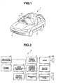
- reference numeral 1 denotes a vehicle (an own vehicle) such as an automobile, and an active drive assist system (ADA: Active Drive Assist system) 2 is installed in the vehicle 1.
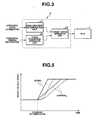
- the active drive assist system 2 comprises a stereo camera unit 3, a millimeter-wave radar unit 4, an image processing unit (IPU) 5, a preview control unit (PCU) 6, an engine control unit (ECU) 7, a vehicle dynamics control unit (VDC) 8, and an integrated unit 9, which are connected to each other via a multiplex communication system such as CAN (Controller Area Network).
- a center display 10, an instrument panel 11, and an audio device 12 are connected to the integrated unit 9 via another communication system (an on-board communication system) using a different communication speed.
- the stereo camera unit 3 has a pair of (right and left) CCD cameras using solid-state image pickup devices such as charge coupled devices (CCDs). These right and left CCD cameras are fixed to a forward part of a ceiling in a cabin with a space of a predetermined reference length therebetween (see Fig. 1), and pick up images of an object outside the vehicle from different viewpoints.
- the stereo camera unit 3 performs A/D conversion of each image (a reference image and a comparative image) picked up by the right and left CCD cameras, and various kinds of corrections, and outputs these image signals to the IPU 5.
- the millimeter-wave radar unit 4 is fixed to, for example, a front bumper member of the vehicle 1 (see Fig. 1).
- the millimeter-wave radar unit 4 has a transmitter-receiver (not shown) which transmits and receives millimeter-waves at predetermined time intervals in a predetermined scanning range in a horizontal direction of the vehicle 1.
- the millimeter-wave radar unit 4 generates a millimeter-wave radar image consisting of two-dimensional distribution information of a three-dimensional object ahead of the vehicle based on the time difference until the transmitted millimeter-waves are reflected by a reflective object, such as the three-dimensional object, and returned, and outputs the image to the IPU 5.
- the IPU 5 performs a three-dimensional object recognition based on the stereo image, the three-dimensional object recognition based on the radar image, and the three-dimensional object recognition by fusing the three-dimensional object recognized based on the stereo image (hereinafter, referred to as "the image three-dimensional object”) and the three-dimensional object recognized based on the radar image (hereinafter, referred to as "the radar three-dimensional object”).
- three-dimensional objects such as white lines on the road, side walls of guard rails, curbs or the like present along the road, and vehicles are recognized by a known operation process using the principle of triangulation of the stereo image or the like.
- a different ID is allocated to each piece of data related to the recognized white lines, the side walls and the three-dimensional objects.
- two or more surfaces of the three-dimensional objects such as the vehicles are often recognized continuously by means of corners formed by these surfaces, and three-dimensional objects having a high likelihood of being such vehicles are registered separately as corner-shaped three-dimensional objects.
- portions with continuous distance values on the radar image are extracted as one three-dimensional object, and an ID is allocated to each piece of data related to the extracted three-dimensional object.
- an identical probability for every combination of each image three-dimensional object with each radar three-dimensional object is determined based on the position and the moving speed of each image three-dimensional object and each radar three-dimensional object, and each combination of the image three-dimensional objects with the radar three-dimensional objects for which the identical probability is equal to or larger than a predetermined value and which has the highest coincidence with each other is recognized as a three-dimensional object (a fusion three-dimensional object) using both the stereo image and the millimeter-wave radar.
- each three-dimensional object comprising the three-dimensional object recognized as a single image three-dimensional object, the three-dimensional object recognized as a single radar three-dimensional object, or a fusion three-dimensional object recognized by the combination of the single image three-dimensional object and the single radar three-dimensional object is recognized ahead of the vehicle.
- the vehicle driving lane is estimated on the basis of the information on the white lines, the side walls or the like recognized from the stereo image and the information on the running conditions of the vehicle 1 obtained from the VDC 8, and a three-dimensional object existing in the estimated vehicle driving lane is extracted. If three-dimensional objects in the vehicle driving lane are extracted, the three-dimensional object that is located closest to the vehicle among those objects is acquired as a preceding vehicle.
- the above-described recognition result of the outside circumstances by the IPU 5 is input to the PCU 6 to control each function of the active drive assist system 2.
- the PCU 6 performs various kinds of active drive assist functions based on the information obtained from the IPU 5 and the VDC 8, and adequately outputs display signals to the center display 10 and the instrument panel 11, outputs buzzer (or audio) signals to the speakers 11a and 12a connected to the instrument panel 11 and the audio device 12, or outputs control signals to the ECU 7 and the VDC 8.
- the active drive assist function carried out by the PCU 6 includes, for example, an alarm function for the vehicle-to-vehicle distance, lane deviations, and lane deviations (meandering) swaying, tire-grip estimating functions, and visibility assist functions, and further includes the vehicle-to-vehicle distance cruise control (Adaptive Cruise Control: ACC) function for performing a constant speed running control and follow-running control with respect to the preceding vehicle according to the recognition result of the preceding vehicle.
- Adaptive Cruise Control: ACC Adaptive Cruise Control
- the vehicle When a driver sets a desired running speed by operating a touch switch provided on the center display 10, the vehicle is subjected to automatic constant speed running if no preceding vehicle is present in the vehicle driving lane, and follow-running control is performed so as to maintain an adequate vehicle-to-vehicle distance if the preceding vehicle at a lower speed than that of the vehicle is acquired in the vehicle driving lane.
- the touch switch of the center display 10 is used to perform/cancel the active drive assist functions, or to switch the display of the center display 10, and the ACC function can be selected by operating a main switch to turn on and off the ACC function, a vehicle speed switch to set the target vehicle speed at the constant speed running, a coast switch for mainly changing and setting the target vehicle speed to a downhill side, a resume switch for mainly changing and setting the target vehicle speed to an uphill side, or the like.
- This ACC control function is turned OFF not only in the event of a system fault when a fault is detected in each unit, but also in the event of fog or rain or degradations of the image pickup environment, such as when the image pickup against a backlight (or a bright background) is attempted, on the basis of the stereo image in the IPU 5, or when a stain on the windshield or a camera lens, a misalignment of the radar based on the millimeter-wave radar image, a stain on the radar cover, or the like is detected. Further, even when the ACC control function is turned ON, the follow running with respect to the preceding vehicle is prohibited if a possibility of mistaken recognition is determined on the basis of the information about recognition types in addition to the information on the preceding vehicle, which is described below.
- Fig. 3 shows a main configuration of the ACC control function performed by the PCU 6, mainly consisting of a mode-changing operation unit 20, a road gradient determination unit 21, and a target speed operation unit 22.
- the target speed operation unit 22 the target vehicle-to-vehicle distance according to the running mode controlled by the mode-changing operation unit 20 is controlled on the basis of the information on the preceding vehicle, such as the speed and the distance of the preceding vehicle acquired by the IPU 5, and the target vehicle speed is corrected according to the gradient of the road determined by the road gradient determination unit 21 and output to the ECU 7 as a target value of the engine output control performed by the ECU 7.
- the mode-changing operation unit 20 basically operates the constant speed running mode and the follow running mode.
- the mode-changing operation unit 20 operates the constant speed running mode and the acceleration/deceleration mode via the VDC 8. These are operated on the basis of the information on the preceding vehicle from the IPU 5.
- the constant speed running mode controls the vehicle speed set by the driver to maintain that speed when no preceding vehicle is present in the driving lane.
- the follow running mode performs the follow running in which an adequate vehicle-to-vehicle distance to the targeted preceding vehicle is maintained when the preceding vehicle is running at a lower speed than that of the vehicle in the driving lane.
- the constant speed running mode maintains the vehicle speed when sight of the preceding vehicle is lost during the follow running mode.
- the result of the mode-change of operation is updated as needed on the basis of the information on the preceding vehicle from the IPU 5.
- the road gradient determination unit 21 determines the road gradient of the running lane of the vehicle by combining at least the engine output control state, the speed change state, and the braking state of the vehicle while paying attention to the change of the running condition of the vehicle corresponding to the change of the road gradient if the road changes from a flat road to a downhill road or an uphill road. More specifically, it is determined that the present road on which the vehicle is running is a downhill road, an uphill road or a flat road from the information on the running condition of the vehicle, such as the engine throttle opening degree information, the speed change of the vehicle, the braking applied or not, and the braking control performed or not.
- the control responsiveness with respect to the target vehicle speed is higher than that on a flat road, and the throttle opening degree of the engine is controlled to be relatively small, and, depending on the acceleration of the vehicle, braking control is performed or braking is applied by the driver.
- the control responsiveness to the target vehicle speed is lower than that on a flat road, the acceleration is relatively small, and the throttle opening degree of the engine is controlled to be relatively large to compensate for this.
- the road gradient of the road can be determined by learning in advance the relationship between a change in the running condition and the road gradient based on the driving characteristics and a braking capacity of the vehicle using a neural network or the like, and inputting the information on the present running condition to the neural network without providing any special sensor such as an inclination sensor.
- the road gradient determination unit 21 Concerning the result of determination of the road gradient by the road gradient determination unit 21, the kinds of road, that is, a flat road, a downhill road, or an uphill road, and the gradient thereof are output to the target speed operation unit 22.
- the target speed operation unit 22 operates the target vehicle speed in each running mode corresponding to the mode-changing instructions from the mode-changing operation unit 20.
- the target vehicle speed is output to the ECU 7, the throttle opening degree is feedback-controlled via an actuator to open/close a throttle valve according to the difference between the target vehicle speed and the actual vehicle speed obtained by the ECU 7, and the vehicle speed is thus controlled.
- the target speed operation unit 22 corrects the target vehicle speed according to the degree of the gradient if it is determined during the follow running mode by the road gradient determination unit 21 that the road surface is not flat. Therefore, the vehicle can be prevented from approaching too close to the preceding vehicle due to an excessive response speed on a downhill road, and control hunting in deceleration and acceleration does not occur. Further, an inadequate increase of the vehicle-to-vehicle distance caused by reduction of the response speed on an uphill road can be prevented.
- the target vehicle speed in the above-described ACC control function is calculated by the program processing in Fig. 4.
- a target vehicle speed calculation routine in Fig. 4 will be described below.
- This target vehicle speed calculation routine is started by turning ON an ACC main switch on the center display 10 under the ACC control executable conditions, and is repeated at predetermined intervals.
- Step S101 the mode-changing operated on the basis of the information on the preceding vehicle from the IPU 5 is read in Step S101, and it is determined in Step S102 whether or not the present mode-changing is the constant speed running mode in which the preceding vehicle in the driving lane is not caught in sight. If the present mode-changing is the constant speed running mode, the program advances from Step S102 to Step S103, calculates the vehicle speed set by the driver as the target vehicle speed, and exits the routine.
- the target vehicle speed is output from the PCU 6 to the ECU 7, and the ECU 7 performs feedback control of the opening degree of the throttle valve so that the difference between the target vehicle speed and the present vehicle speed converges to zero.
- the throttle opening degree is increased, the engine speed is increased, and the vehicle speed is increased.
- the throttle opening degree is reduced, engine braking is applied to perform a deceleration. Therefore, the vehicle 1 is automatically controlled so as to run at the constant speed set by the driver.
- Step S102 if the present mode-changing is not the constant speed running mode, the program advances from Step S102 to Step S104, and if the IPU 5 cannot have sight of the preceding vehicle because it is running on a curve, performing a lane change, or the like, it is determined whether or not the preceding vehicle is temporarily lost from sight.
- Step S104 if it is determined that the preceding vehicle is lost from sight, the program advances from Step S104 to Step S105, and a counter T to count the duration for which the loss continues counts down from the previous value (T ⁇ T - 1).
- An initial value to provide a holding time for maintaining the present vehicle speed mode (for example, 2 seconds) when the preceding vehicle is lost from sight during the follow running mode is set in the counter T, and the counter counts down from the initial value immediately after the preceding vehicle is lost from sight.
- Step S106 it is checked whether or not the counter T reaches zero. If T > 0, the duration time after the preceding vehicle is lost from sight has not yet elapsed, the program advances from Step S106 to Step S107, maintains the target vehicle speed at the target vehicle speed immediately before the preceding vehicle was lost from sight, and the program then exits the routine.
- the present mode-changing changes from the follow running mode to the constant speed running mode.
- the opening degree of the throttle valve is feedback-controlled according to the difference between the target vehicle speed output from the PCU 6 to the ECU 7 and the present vehicle speed, and this control is maintained so that the vehicle speed is equal to the target vehicle speed when the preceding vehicle cannot be caught in sight.
- the present vehicle speed mode is maintained without immediately performing the acceleration, and a buffer zone for the control is provided, preventing the driver from feeling any incompatibility.
- Step S106 the routine is repeated, and when T ⁇ 0 in Step S106, and the lost state of the preceding vehicle elapses the speed-maintaining time, it is determined that the preceding vehicle is not temporarily lost, but n preceding vehicle is present in the driving lane (the preceding vehicle is absent), the program exits from Step S106 to Step S103, and the acceleration is immediately started by setting the target vehicle speed to be the set vehicle speed. If the target vehicle speed changes, the preceding vehicle being found again, the mode-changing changes to the constant speed running mode, and the vehicle speed is rapidly returned to the set vehicle speed without the driver experiencing any sense of hesitation (feeling of defective acceleration).
- Step S104 if it is not determined that the preceding vehicle is lost, and the preceding vehicle in the driving lane is adequately acquired, the program advances from Step S104 to Step S108, and calculates the target vehicle speed using the controlled value based on an adequate vehicle-to-vehicle distance to the preceding vehicle. For example, a target value of the vehicle-to-vehicle distance to an object to be followed is obtained by multiplying the vehicle speed by the set time, the controlled value according to the difference between the target vehicle-to-vehicle distance and the actual vehicle-to-vehicle distance and the relative speed between the vehicle and the preceding vehicle is added to the speed of the preceding vehicle, and the target vehicle speed is thereby operated.
- the mode-changing is the follow running mode.
- the opening of the throttle valve is feedback-controlled according to the difference between the target vehicle speed output from the PCU 6 to the ECU 7 and the actual vehicle speed.
- the vehicle-to-vehicle distance between the vehicle and the preceding vehicle is controlled so as to be equal to the target vehicle-to-vehicle distance by performing a deceleration using an automatic brake from the PCU 6 via the VDC 8 as necessary, such as when another vehicle cuts into the running lane of the vehicle.
- the vehicle 1 thereby performs the follow running while maintaining an adequate vehicle-to-vehicle distance to the preceding vehicle thereby.
- Step S109 determines whether the gradient of the road on which the vehicle is presently running is a downhill road or an uphill road, not a flat road. If it is determined that the road is not inclined, that is, the road is flat, the program exits the routine without changing the target vehicle speed previously calculated in Step S108. If it is determined that the road is a downhill road, or an uphill road, the program advances to Step S110, and corrects the previously calculated target vehicle speed according to the gradient.
- the target vehicle speed increase rate (the difference between the target vehicle speed calculated this time and the target vehicle speed calculated previously) is checked, and the acceleration of the vehicle on the downhill road is limited by reducing the target vehicle speed calculated this time so that the target vehicle speed increase rate is not more than an upper limit value set according to the gradient.
- the difference between the actual vehicle speed on the uphill road and the target vehicle speed is set to be larger than that on the flat road by increasing the target vehicle speed calculated this time so that the target vehicle speed increase rate is not less than a lower limit value set according to the gradient, and any sense of hesitation due to defective accelerations is eliminated to maintain an adequate vehicle-to-vehicle distance.
- the target vehicle speed increase rate of the vehicle on a downhill road is set to be smaller than that on a flat road, or the target vehicle speed increase rate of the vehicle on an uphill road is set to be larger than that on a flat road, and as indicated by a broken line in the figure, the response delay of the actual vehicle speed to the target vehicle speed is set to be substantially constant irrespective of the gradient.
- the preceding vehicle may be caught in sight by using either of them, or the preceding vehicle may be caught in sight singularly or by a combination of the infrared-laser radar with a monocular camera.
- the vehicle active drive assist system of the present invention can eliminate the influence of changes of the acceleration/deceleration responsiveness due to the road gradient, and can realize the follow-running to maintain an adequate vehicle-to-vehicle distance to the preceding vehicle.
Landscapes
- Engineering & Computer Science (AREA)
- Transportation (AREA)
- Mechanical Engineering (AREA)
- Chemical & Material Sciences (AREA)
- Combustion & Propulsion (AREA)
- Automation & Control Theory (AREA)
- Controls For Constant Speed Travelling (AREA)
- Control Of Driving Devices And Active Controlling Of Vehicle (AREA)
- Control Of Vehicle Engines Or Engines For Specific Uses (AREA)
Applications Claiming Priority (2)
| Application Number | Priority Date | Filing Date | Title |
|---|---|---|---|
| JP2003431259 | 2003-12-25 | ||
| JP2003431259A JP2005186813A (ja) | 2003-12-25 | 2003-12-25 | 車両用運転支援装置 |
Publications (2)
| Publication Number | Publication Date |
|---|---|
| EP1547847A2 true EP1547847A2 (de) | 2005-06-29 |
| EP1547847A3 EP1547847A3 (de) | 2007-02-14 |
Family
ID=34545046
Family Applications (1)
| Application Number | Title | Priority Date | Filing Date |
|---|---|---|---|
| EP04258054A Withdrawn EP1547847A3 (de) | 2003-12-25 | 2004-12-22 | Abstandsbezogenes Fahrgeschwindigkeitsregelsystem |
Country Status (3)
| Country | Link |
|---|---|
| US (1) | US20050143895A1 (de) |
| EP (1) | EP1547847A3 (de) |
| JP (1) | JP2005186813A (de) |
Cited By (6)
| Publication number | Priority date | Publication date | Assignee | Title |
|---|---|---|---|---|
| WO2008087092A1 (de) * | 2007-01-16 | 2008-07-24 | Continental Automotive Gmbh | Gemeinsamer kontroller für verschiedene fahrerassistenzsysteme |
| FR2937936A1 (fr) * | 2008-11-03 | 2010-05-07 | Valeo Vision Sas | Procede d'assistance a la conduite pour vehicule automobile |
| CN102618906A (zh) * | 2012-01-18 | 2012-08-01 | 清华大学 | 一种龙门架式汽车涂装输送机 |
| CN104169154A (zh) * | 2012-03-15 | 2014-11-26 | 丰田自动车株式会社 | 车辆行驶控制装置 |
| WO2016122383A1 (en) * | 2015-01-28 | 2016-08-04 | Scania Cv Ab | Method and control unit for adjusting a time gap |
| CN113879304A (zh) * | 2021-10-21 | 2022-01-04 | 中寰卫星导航通信有限公司 | 一种车辆控制方法、装置、设备及存储介质 |
Families Citing this family (29)
| Publication number | Priority date | Publication date | Assignee | Title |
|---|---|---|---|---|
| JP4862036B2 (ja) * | 2006-03-06 | 2012-01-25 | 日立オートモティブシステムズ株式会社 | 自動車の制御装置及び制御方法 |
| JP4938542B2 (ja) * | 2007-04-27 | 2012-05-23 | トヨタ自動車株式会社 | 車両の車速制御装置 |
| TWM353849U (en) * | 2008-09-17 | 2009-04-01 | Jyh-Chiang Liou | Integrated driving assistance apparatus |
| KR101023334B1 (ko) * | 2009-06-02 | 2011-03-22 | 삼성전기주식회사 | 자동차용 카메라 모듈 및 이를 이용한 주차 안내선 표시방법 |
| SE534036C2 (sv) * | 2009-06-10 | 2011-04-12 | Scania Cv Ab | Metod och modul för bestämning av hastighetsbörvärden till ett fordons styrsystem. |
| JP5039765B2 (ja) * | 2009-09-17 | 2012-10-03 | 日立オートモティブシステムズ株式会社 | 車両制御装置 |
| JP5349234B2 (ja) * | 2009-09-25 | 2013-11-20 | 本田技研工業株式会社 | 補助動力装置付き二輪車 |
| JP5887219B2 (ja) * | 2012-07-03 | 2016-03-16 | クラリオン株式会社 | 車線逸脱警報装置 |
| US20140198195A1 (en) * | 2013-01-17 | 2014-07-17 | Electronics And Telecommunications Research Institute | Terahertz health checker |
| DE102013011624A1 (de) * | 2013-07-12 | 2015-01-15 | Wabco Gmbh | Verfahren und Vorrichtung zur automatischen Regelung einer Längsdynamik eines Kraftfahrzeugs |
| GB2519533B (en) * | 2013-10-23 | 2018-04-04 | Jaguar Land Rover Ltd | Vehicle speed control system |
| US20150258994A1 (en) * | 2014-03-17 | 2015-09-17 | Ford Global Technologies, Llc | Vehicle with mass and grade responsive cruise control |
| DE102014208500A1 (de) * | 2014-05-07 | 2015-11-12 | Volkswagen Aktiengesellschaft | Verfahren und Vorrichtung zur Schätzung einer zu erwartenden Empfangsqualität |
| JP6094530B2 (ja) | 2014-05-30 | 2017-03-15 | 株式会社デンソー | 運転支援装置および運転支援プログラム |
| US10112609B2 (en) | 2014-06-10 | 2018-10-30 | Denso Corporation | Collision avoidance apparatus |
| SE1451022A1 (sv) | 2014-09-03 | 2016-01-19 | Scania Cv Ab | Styrenhet och metod för att reglera hastigheten på ett fordon i ett avståndsreglerat fordonståg vid backtagning |
| US9827970B2 (en) * | 2015-03-11 | 2017-11-28 | Ford Global Technologies, Llc | Vehicle stopping assist and speed control system |
| US9682705B2 (en) * | 2015-08-13 | 2017-06-20 | Ford Global Technologies, Llc | Vehicle having ACC stop and go with braking auto-hold to increase engine autostop availability |
| GB2552021B (en) * | 2016-07-08 | 2019-08-28 | Jaguar Land Rover Ltd | Improvements in vehicle speed control |
| JP6528213B2 (ja) * | 2016-11-08 | 2019-06-12 | 本田技研工業株式会社 | 車両制御装置、車両制御方法、および車両制御プログラム |
| WO2019166141A1 (en) * | 2018-03-01 | 2019-09-06 | Jaguar Land Rover Limited | Vehicle control method and apparatus |
| WO2020072046A1 (en) * | 2018-10-03 | 2020-04-09 | Hewlett-Packard Development Company, L.P. | Audio feedback devices |
| JP7358133B2 (ja) * | 2019-09-13 | 2023-10-10 | ダイムラー トラック エージー | 隊列走行制御装置 |
| JP6961031B2 (ja) * | 2020-04-08 | 2021-11-05 | 三菱電機株式会社 | 自動二輪車の運転支援装置 |
| US12043309B2 (en) * | 2020-08-17 | 2024-07-23 | Magna Electronics Inc. | Vehicular control system with enhanced lane centering |
| JP7508945B2 (ja) * | 2020-08-25 | 2024-07-02 | 日産自動車株式会社 | 車両の制御方法および制御装置 |
| JP7578089B2 (ja) * | 2021-10-05 | 2024-11-06 | トヨタ自動車株式会社 | 自動駐車システム、設定方法及びコンピュータプログラム |
| JP7755970B2 (ja) * | 2021-10-14 | 2025-10-17 | 株式会社Subaru | 自動後退運転制御装置 |
| US12246747B2 (en) * | 2023-05-31 | 2025-03-11 | Plusai, Inc. | Adaptive and fuel efficient planning and control |
Family Cites Families (13)
| Publication number | Priority date | Publication date | Assignee | Title |
|---|---|---|---|---|
| JPH06255389A (ja) * | 1991-02-26 | 1994-09-13 | Mitsubishi Electric Corp | 車両の走行制御装置 |
| DE4443522C2 (de) * | 1994-12-07 | 1999-11-25 | Daimler Chrysler Ag | Verfahren zur Bestimmung der Fahrbahnneigung |
| JP3708180B2 (ja) * | 1995-09-14 | 2005-10-19 | 富士重工業株式会社 | 自動ブレーキ制御装置 |
| JP3468001B2 (ja) * | 1996-12-16 | 2003-11-17 | 日産自動車株式会社 | 車両用走行制御装置 |
| US6076036A (en) * | 1998-10-05 | 2000-06-13 | Price; Christopher C. | Vehicle cruise control |
| DE19859743A1 (de) * | 1998-12-23 | 2000-06-29 | Man Nutzfahrzeuge Ag | Verfahren und Vorrichtung zur Regelung der Fahrweise eines Kraftfahrzeuges |
| US6374173B1 (en) * | 1999-05-28 | 2002-04-16 | Freightliner Llc | Terrain adaptive cruise control |
| JP3723028B2 (ja) * | 1999-12-28 | 2005-12-07 | 本田技研工業株式会社 | 路面勾配検出装置及び発進クラッチの制御装置 |
| JP3909647B2 (ja) * | 2000-12-13 | 2007-04-25 | 本田技研工業株式会社 | オートクルーズ装置 |
| JP4489333B2 (ja) * | 2001-09-26 | 2010-06-23 | 日産自動車株式会社 | 車両の駆動力制御装置 |
| US7260465B2 (en) * | 2002-04-30 | 2007-08-21 | Ford Global Technology, Llc | Ramp identification in adaptive cruise control |
| JP4039184B2 (ja) * | 2002-08-29 | 2008-01-30 | 株式会社アドヴィックス | クリープ走行制御装置 |
| JP4254586B2 (ja) * | 2004-03-15 | 2009-04-15 | 日産自動車株式会社 | 減速制御装置 |
-
2003
- 2003-12-25 JP JP2003431259A patent/JP2005186813A/ja active Pending
-
2004
- 2004-12-21 US US11/019,003 patent/US20050143895A1/en not_active Abandoned
- 2004-12-22 EP EP04258054A patent/EP1547847A3/de not_active Withdrawn
Non-Patent Citations (1)
| Title |
|---|
| None |
Cited By (12)
| Publication number | Priority date | Publication date | Assignee | Title |
|---|---|---|---|---|
| WO2008087092A1 (de) * | 2007-01-16 | 2008-07-24 | Continental Automotive Gmbh | Gemeinsamer kontroller für verschiedene fahrerassistenzsysteme |
| FR2937936A1 (fr) * | 2008-11-03 | 2010-05-07 | Valeo Vision Sas | Procede d'assistance a la conduite pour vehicule automobile |
| EP2189348A1 (de) * | 2008-11-03 | 2010-05-26 | Valeo Vision | Verfahren zur Unterstützung des Fahrens eines Fahrzeugs |
| CN102618906A (zh) * | 2012-01-18 | 2012-08-01 | 清华大学 | 一种龙门架式汽车涂装输送机 |
| CN104169154A (zh) * | 2012-03-15 | 2014-11-26 | 丰田自动车株式会社 | 车辆行驶控制装置 |
| EP2826685A4 (de) * | 2012-03-15 | 2016-03-16 | Toyota Motor Co Ltd | Fahrtsteuerungsvorrichtung für ein fahrzeug |
| US9610950B2 (en) | 2012-03-15 | 2017-04-04 | Toyota Jidosha Kabushiki Kaisha | Vehicle travel control apparatus |
| WO2016122383A1 (en) * | 2015-01-28 | 2016-08-04 | Scania Cv Ab | Method and control unit for adjusting a time gap |
| KR20170107008A (ko) * | 2015-01-28 | 2017-09-22 | 스카니아 씨브이 악티에볼라그 | 시간 간격을 조정하기 위한 방법 및 제어 유닛 |
| EP3250429A4 (de) * | 2015-01-28 | 2019-01-16 | Scania CV AB | Verfahren und steuerungseinheit zur einstellung einer zeitlücke |
| US10293821B2 (en) | 2015-01-28 | 2019-05-21 | Scania Cv Ab | Method and control unit for adjusting a time gap |
| CN113879304A (zh) * | 2021-10-21 | 2022-01-04 | 中寰卫星导航通信有限公司 | 一种车辆控制方法、装置、设备及存储介质 |
Also Published As
| Publication number | Publication date |
|---|---|
| EP1547847A3 (de) | 2007-02-14 |
| US20050143895A1 (en) | 2005-06-30 |
| JP2005186813A (ja) | 2005-07-14 |
Similar Documents
| Publication | Publication Date | Title |
|---|---|---|
| EP1547847A2 (de) | Abstandsbezogenes Fahrgeschwindigkeitsregelsystem | |
| US8010274B2 (en) | Vehicle driving support apparatus with target position arrival determination | |
| US10160450B2 (en) | Travel control device for vehicle | |
| JP6275213B2 (ja) | 車両の追従発進制御装置 | |
| EP1455323B1 (de) | Fahrassistenzsystem für Fahrzeuge | |
| CN102205845B (zh) | 车辆的驾驶辅助装置 | |
| EP3674157B1 (de) | Fahrzeugsteuergerät | |
| US8762021B2 (en) | Driving support system | |
| JP6158523B2 (ja) | 車間距離制御装置 | |
| EP1564703B1 (de) | Fahrassistenzsystem für Fahrzeuge | |
| US8938354B2 (en) | Driving support apparatus for vehicle | |
| JP2020201734A (ja) | 車両制御装置 | |
| JP3970486B2 (ja) | 車両用走行制御装置 | |
| WO2021235043A1 (ja) | 車両制御装置 | |
| JP2005081999A (ja) | 車両用運転支援装置 | |
| JP4294450B2 (ja) | 車両用運転支援装置 | |
| JP2002248965A (ja) | 車輌用走行制御装置 | |
| JP4635721B2 (ja) | 車両のオートクルーズ装置 | |
| JP4824118B2 (ja) | 車両の運転支援装置 | |
| JP3720117B2 (ja) | 車両の警報装置 | |
| US20060111831A1 (en) | Vehicle driving support apparatus | |
| JP2006298254A (ja) | 走行支援装置 | |
| JP2021039690A (ja) | 車両運転支援方法及び車両運転支援システム | |
| JP4163074B2 (ja) | 車両用運転支援装置 | |
| JP4904983B2 (ja) | 物体検出装置 |
Legal Events
| Date | Code | Title | Description |
|---|---|---|---|
| PUAI | Public reference made under article 153(3) epc to a published international application that has entered the european phase |
Free format text: ORIGINAL CODE: 0009012 |
|
| AK | Designated contracting states |
Kind code of ref document: A2 Designated state(s): AT BE BG CH CY CZ DE DK EE ES FI FR GB GR HU IE IS IT LI LT LU MC NL PL PT RO SE SI SK TR |
|
| AX | Request for extension of the european patent |
Extension state: AL BA HR LV MK YU |
|
| PUAL | Search report despatched |
Free format text: ORIGINAL CODE: 0009013 |
|
| AK | Designated contracting states |
Kind code of ref document: A3 Designated state(s): AT BE BG CH CY CZ DE DK EE ES FI FR GB GR HU IE IS IT LI LT LU MC NL PL PT RO SE SI SK TR |
|
| AX | Request for extension of the european patent |
Extension state: AL BA HR LV MK YU |
|
| AKX | Designation fees paid | ||
| REG | Reference to a national code |
Ref country code: DE Ref legal event code: 8566 |
|
| STAA | Information on the status of an ep patent application or granted ep patent |
Free format text: STATUS: THE APPLICATION IS DEEMED TO BE WITHDRAWN |
|
| 18D | Application deemed to be withdrawn |
Effective date: 20070816 |