EP1547784A2 - Réservoir de liquide, système d'alimentation de liquide, sa méthode de fabrication, sa carte de circuit et cartouche contenant du liquide - Google Patents
Réservoir de liquide, système d'alimentation de liquide, sa méthode de fabrication, sa carte de circuit et cartouche contenant du liquide Download PDFInfo
- Publication number
- EP1547784A2 EP1547784A2 EP04030458A EP04030458A EP1547784A2 EP 1547784 A2 EP1547784 A2 EP 1547784A2 EP 04030458 A EP04030458 A EP 04030458A EP 04030458 A EP04030458 A EP 04030458A EP 1547784 A2 EP1547784 A2 EP 1547784A2
- Authority
- EP
- European Patent Office
- Prior art keywords
- ink
- light emitting
- container
- liquid container
- recording
- Prior art date
- Legal status (The legal status is an assumption and is not a legal conclusion. Google has not performed a legal analysis and makes no representation as to the accuracy of the status listed.)
- Granted
Links
- 239000007788 liquid Substances 0.000 title claims abstract description 94
- 238000004519 manufacturing process Methods 0.000 title claims description 19
- 230000004044 response Effects 0.000 claims abstract description 13
- 108091008695 photoreceptors Proteins 0.000 claims abstract description 11
- 239000000758 substrate Substances 0.000 claims description 56
- 238000000034 method Methods 0.000 claims description 42
- 239000000976 ink Substances 0.000 description 495
- 230000008569 process Effects 0.000 description 38
- 239000000463 material Substances 0.000 description 17
- 238000010200 validation analysis Methods 0.000 description 15
- 238000012790 confirmation Methods 0.000 description 9
- 238000004891 communication Methods 0.000 description 7
- 230000006870 function Effects 0.000 description 7
- 238000002347 injection Methods 0.000 description 7
- 239000007924 injection Substances 0.000 description 7
- 238000007789 sealing Methods 0.000 description 7
- 239000004065 semiconductor Substances 0.000 description 7
- 230000008054 signal transmission Effects 0.000 description 7
- 239000003086 colorant Substances 0.000 description 6
- 238000010586 diagram Methods 0.000 description 6
- 230000000694 effects Effects 0.000 description 6
- 230000005856 abnormality Effects 0.000 description 5
- 230000003287 optical effect Effects 0.000 description 5
- 238000012545 processing Methods 0.000 description 5
- 239000012530 fluid Substances 0.000 description 4
- 230000007246 mechanism Effects 0.000 description 4
- 239000000203 mixture Substances 0.000 description 4
- 238000011112 process operation Methods 0.000 description 4
- 230000005540 biological transmission Effects 0.000 description 3
- 238000006243 chemical reaction Methods 0.000 description 3
- 238000001514 detection method Methods 0.000 description 3
- 230000009467 reduction Effects 0.000 description 3
- 239000011347 resin Substances 0.000 description 3
- 229920005989 resin Polymers 0.000 description 3
- 230000002159 abnormal effect Effects 0.000 description 2
- 239000011358 absorbing material Substances 0.000 description 2
- 238000009835 boiling Methods 0.000 description 2
- 125000004122 cyclic group Chemical group 0.000 description 2
- 210000003128 head Anatomy 0.000 description 2
- 230000006872 improvement Effects 0.000 description 2
- 230000004048 modification Effects 0.000 description 2
- 238000012986 modification Methods 0.000 description 2
- 230000000630 rising effect Effects 0.000 description 2
- 239000000565 sealant Substances 0.000 description 2
- 238000003860 storage Methods 0.000 description 2
- WBMKMLWMIQUJDP-STHHAXOLSA-N (4R,4aS,7aR,12bS)-4a,9-dihydroxy-3-prop-2-ynyl-2,4,5,6,7a,13-hexahydro-1H-4,12-methanobenzofuro[3,2-e]isoquinolin-7-one hydrochloride Chemical compound Cl.Oc1ccc2C[C@H]3N(CC#C)CC[C@@]45[C@@H](Oc1c24)C(=O)CC[C@@]35O WBMKMLWMIQUJDP-STHHAXOLSA-N 0.000 description 1
- BQCADISMDOOEFD-UHFFFAOYSA-N Silver Chemical compound [Ag] BQCADISMDOOEFD-UHFFFAOYSA-N 0.000 description 1
- 230000004308 accommodation Effects 0.000 description 1
- 230000009471 action Effects 0.000 description 1
- 238000005054 agglomeration Methods 0.000 description 1
- 230000002776 aggregation Effects 0.000 description 1
- 238000013459 approach Methods 0.000 description 1
- 230000008901 benefit Effects 0.000 description 1
- 230000000903 blocking effect Effects 0.000 description 1
- 230000008859 change Effects 0.000 description 1
- 238000011109 contamination Methods 0.000 description 1
- 230000008021 deposition Effects 0.000 description 1
- 238000007599 discharging Methods 0.000 description 1
- 238000006073 displacement reaction Methods 0.000 description 1
- 239000013013 elastic material Substances 0.000 description 1
- 239000000835 fiber Substances 0.000 description 1
- PCHJSUWPFVWCPO-UHFFFAOYSA-N gold Chemical compound [Au] PCHJSUWPFVWCPO-UHFFFAOYSA-N 0.000 description 1
- 239000010931 gold Substances 0.000 description 1
- 229910052737 gold Inorganic materials 0.000 description 1
- 238000005470 impregnation Methods 0.000 description 1
- 230000005499 meniscus Effects 0.000 description 1
- 229910052751 metal Inorganic materials 0.000 description 1
- 239000002184 metal Substances 0.000 description 1
- 238000012856 packing Methods 0.000 description 1
- 239000000049 pigment Substances 0.000 description 1
- 230000002265 prevention Effects 0.000 description 1
- 238000001454 recorded image Methods 0.000 description 1
- 229910052709 silver Inorganic materials 0.000 description 1
- 239000004332 silver Substances 0.000 description 1
- 230000008023 solidification Effects 0.000 description 1
- 238000007711 solidification Methods 0.000 description 1
- 239000004753 textile Substances 0.000 description 1
- 239000012780 transparent material Substances 0.000 description 1
- 238000012795 verification Methods 0.000 description 1
- 230000000007 visual effect Effects 0.000 description 1
- 229910052727 yttrium Inorganic materials 0.000 description 1
Images


Classifications
-
- B—PERFORMING OPERATIONS; TRANSPORTING
- B41—PRINTING; LINING MACHINES; TYPEWRITERS; STAMPS
- B41J—TYPEWRITERS; SELECTIVE PRINTING MECHANISMS, i.e. MECHANISMS PRINTING OTHERWISE THAN FROM A FORME; CORRECTION OF TYPOGRAPHICAL ERRORS
- B41J2/00—Typewriters or selective printing mechanisms characterised by the printing or marking process for which they are designed
- B41J2/005—Typewriters or selective printing mechanisms characterised by the printing or marking process for which they are designed characterised by bringing liquid or particles selectively into contact with a printing material
- B41J2/01—Ink jet
- B41J2/17—Ink jet characterised by ink handling
- B41J2/175—Ink supply systems ; Circuit parts therefor
- B41J2/17503—Ink cartridges
- B41J2/17543—Cartridge presence detection or type identification
- B41J2/17546—Cartridge presence detection or type identification electronically
-
- B—PERFORMING OPERATIONS; TRANSPORTING
- B41—PRINTING; LINING MACHINES; TYPEWRITERS; STAMPS
- B41J—TYPEWRITERS; SELECTIVE PRINTING MECHANISMS, i.e. MECHANISMS PRINTING OTHERWISE THAN FROM A FORME; CORRECTION OF TYPOGRAPHICAL ERRORS
- B41J2/00—Typewriters or selective printing mechanisms characterised by the printing or marking process for which they are designed
- B41J2/005—Typewriters or selective printing mechanisms characterised by the printing or marking process for which they are designed characterised by bringing liquid or particles selectively into contact with a printing material
- B41J2/01—Ink jet
- B41J2/015—Ink jet characterised by the jet generation process
- B41J2/04—Ink jet characterised by the jet generation process generating single droplets or particles on demand
- B41J2/045—Ink jet characterised by the jet generation process generating single droplets or particles on demand by pressure, e.g. electromechanical transducers
- B41J2/04501—Control methods or devices therefor, e.g. driver circuits, control circuits
- B41J2/04581—Control methods or devices therefor, e.g. driver circuits, control circuits controlling heads based on piezoelectric elements
-
- B—PERFORMING OPERATIONS; TRANSPORTING
- B41—PRINTING; LINING MACHINES; TYPEWRITERS; STAMPS
- B41J—TYPEWRITERS; SELECTIVE PRINTING MECHANISMS, i.e. MECHANISMS PRINTING OTHERWISE THAN FROM A FORME; CORRECTION OF TYPOGRAPHICAL ERRORS
- B41J2/00—Typewriters or selective printing mechanisms characterised by the printing or marking process for which they are designed
- B41J2/005—Typewriters or selective printing mechanisms characterised by the printing or marking process for which they are designed characterised by bringing liquid or particles selectively into contact with a printing material
- B41J2/01—Ink jet
- B41J2/015—Ink jet characterised by the jet generation process
- B41J2/04—Ink jet characterised by the jet generation process generating single droplets or particles on demand
- B41J2/045—Ink jet characterised by the jet generation process generating single droplets or particles on demand by pressure, e.g. electromechanical transducers
- B41J2/04501—Control methods or devices therefor, e.g. driver circuits, control circuits
- B41J2/04588—Control methods or devices therefor, e.g. driver circuits, control circuits using a specific waveform
Definitions
- the present invention relates to a liquid container, a liquid supplying system using the container, a manufacturing method for the container, a circuit board for the container, and a liquid containing cartridge, more particularly to a liquid container and a liquid supplying system, more particularly, to a liquid container which is capable of notifying a state of the liquid container using light emitting means such as a LED, the state including an ink remaining amount of an ink container for ink jet recording, and to a liquid supplying system using such a container, to a manufacturing method for such a container, to a circuit board for such a container and to a liquid containing cartridge using such a container.
- a recording device for recording desired, letters, images or the like on a recording material such as recording sheet of paper or the like to output information in personal computers, facsimile machines and so on.
- a recording device there is a strong demand for high resolution, high speed and high precision recording is desired both in the fields of business use and personal use, and in addition, there is also a demand for cost reduction and reliability.
- the ink jet recording apparatus comprises a recording head including an ejection outlet and an element for generated energy for ejecting ink through the ejection outlet (a electrothermal transducer element for generating thermal energy effective to create film boiling in the ink, for example), wherein ink is detected onto the recording material in accordance with the desired information to be recorded.
- a plurality of ejection outlets are arranged in a line or in lines, and energy generating elements are disposed inside the respective ejection outlets.
- the recording head and the ink container which is a liquid container for containing the ink to be supplied to the recording head, are unified to form a unit. Different units are provided depending on the colors and/or kinds of the ink and are supported on a carriage.
- the ink jet recording head is a separate member from an ink container in the form of a cartridge (ink cartridge), wherein the ink jet recording head has a plurality of ejection portions correspondingly to the colors and kinds of the ink (for example, black (K), yellow (Y), magenta (M) and cyan (C) inks), and a plurality of cartridges are loaded.
- the cartridge integrally having the ink container and the recording head is detachably mountable to the main assembly of the recording device as a unit, and in the latter structure, only the ink cartridge is detachably mountable with the recording head held in the main assembly of the recording device.
- the performance of the ink jet recording head has been remarkably improved to meet recent demand for high precision recording and high image quality recording.
- a larger number of ejection outlets and energy generating elements are provided in the recording head, and an increasing number of energy generating elements are simultaneously driven, by which the recording speed and therefore recording throughput are improved.
- Japanese Laid-open Patent Application Hei 7- 076104 discloses that in a recording head having such high performance, an ink jet recording head 1105 is provided with a storing element such as an EEPROM storing individual information of the recording head 1105 per se, to provide the service life and/or the time when the ink jet recording head 1105 is to be exchanged.
- a storing element such as an EEPROM storing individual information of the recording head 1105 per se
- Figure 27 illustrates the structure.
- the electric signal wiring from the recording head 1105 having the EEPROM 1018 includes only those designated by 1016 (a) -1016 -1016 (c) which are expanded from a connector 1028 on the recording head 1105 and are connected to CPU Central-Processing-Unit) 1300 into control circuit portion provided in the main assembly of the recording device through a flexible cable 1206.
- the ink cartridge carries a storing element storing information such as ink remaining amount, and the information can be presented to the main assembly side of the recording device.
- Figures 28 and 29 illustrate two examples.
- the plurality of ink cartridges 1001K,1001Y,1001M and 1001C have respective storing elements 1100A, 1100B, 1100C.
- the signal lines for the respective storing elements are gathered on the recording head 1105 together with the signal lines for the storing elements 1018, and the group of the signal line 1016 is connected to the CPU1300 in the control circuit portion of the main assembly of the recording device from the connector 1028 on the recording head 1105 through the flexible cable 1206.
- storing elements 1100A - 1100D for storing various information are directly connected to the CPU1300 in the control circuit portion of the main assembly of the recording device not through the recording head 1105 to effect preferable operation control.
- the ink has been improved. More particularly, the components and composition ratios of the recently used inks are complicated and seventeen in consideration of various properties in order to accomplish high recording performance.
- some ink in order to enhance the weather-resistant property of the ink and the robustness of the recorded image, some ink contain a pigment component in addition to dye components; in order to meet the demand for high speed printing, a resin material component is added to enhance the fixing; and the composition is determined in consideration of the chemical reaction between different color inks (in the case of multi-color recording).
- the kind of the ink may be changed depending on the materials of the recording material (paper designed particularly for ink jet recording, plain paper, resin material sheet, textile or the like) and/or depending on the desired visual effect (glossiness, use of gold color and/or silver color).
- Such ink works properly when only same kinds of inks are used, thus permitting high quality recording.
- the different kinds of inks are mixed inside one ejection portion with the result of reaction between the different kinds of inks and agglomeration or solidification. If this occurs, the recording operation is damaged by deposition on the ink supply passage in the ejection portion, the liquid passage in the ejection outlet or the side having the ejection outlets. Therefore, considerations have to be paid to avoid mixture of the different kind inks in the recording device. Therefore, it is strongly desired that mounting of an ink cartridge to a wrong position (different color position) is prevented.
- the first method to do this is to different configurations of the ink cartridges are used for different inks, thus preventing the ink cartridges from being mounted to wrong positions.
- the manufacturing cost of the ink cartridges is very high, and storage and management of ink cartridges having different configurations are cumbersome.
- ink cartridges 1001K - 1001C have storing elements 1100A - 1100D for storing data indicative of the kinds of the ink contained therein, respectively.
- Japanese Laid-open Patent Application Hei 6- 155769 discloses that storing element of the ink cartridge is connected to the electric circuit of the main assembly of the recording device to permit the kinds of the ink to be recognized by difference in the voltage.
- U. S. Patent 6196670 discloses a control IC in the main assembly of the recording device is connected to the storing elements storing the data indicative of the kind of the ink contained therein, date and time of manufacture thereof, so that data is read and written. If an ink cartridge is mounted to a wrong position, the event is recognized on the basis of information in the ink cartridge, and is notified to the user, thus the inconveniences can be avoided beforehand.
- the ink cartridges 1001A - 1001D and the kind of the ink in the ink cartridge1001A - 1001D can be recognized by the CPU 1300 of the main assembly of the recording device reading the information in the storing elements 1018 and 1100A - 1100D, and in addition, the service gives of the recording head 1105 and the ink cartridge1001A - 1001D and timing of exchange thereof can be appropriately determined. Additionally, by setting a condition of a refreshing process for maintaining the optimum recording condition the ink ejection performance of the recording head in accordance with the kinds of the ink, satisfy recording
- Japanese Laid-open Patent Application Hei 4- 275156 discloses another example of the structures for appropriately notifying the service life of the recording head 105 or ink cartridges 1001A- 1001D and the timing of exchange thereof.
- a cartridge integrally having t recording head and ink container is provided with a light emitting portion in the form of LED, and the ink remaining amount can be notified in accordance with the information of the storing element storing the number of recording electric power supplies for the cartridge.
- the ink cartridge carries the storing element for storing the various information including the kind of the ink in addition to the storing element 1018 carried on the storing element 1018
- all of the storing elements have to be electrically connected to the CPU1300 of the control circuit portion in the main assembly of the recording device to permit communication of information therebetween. Therefore, with the increase of the number of the storing elements, the number of the signal lines 1016 increases for connecting them.
- the connecting portions for connection between the storing elements provided in both of the recording head and a plurality of ink cartridges and the CPU1300 of the control circuit portion in the main assembly of the recording device have to be permanently provided.
- four color inks black, yellow, magenta and cyan
- four ink cartridges 1001K, 1001Y, 1001M and 1001C are simultaneously mounted on the main assembly of the recording device.
- the signal line 1016 is necessary for each of the four storing element1100A-s 1100D of the ink cartridges 1001K, 1001Y, 1001M and 1001C, wherein two or more signal lines 1016 are provided for each of the storing elements.
- recording head 1105 is provided with a storing element 1018, three, for example, signal lines 1016 are required in addition to the lines for the storing elements of the ink cartridge.
- connection step becomes cumbersome since the reliability of the electrical connections have to be maintained.
- the mounting and demounting are carried out by the user, the complication of the connection step is not desirable.
- the main assembly of the recording device has to have a large number of contacts and/or wiring leads for connection with the signal lines 1016 with the result of manufacturing cost rise and complication of structure.
- the ink cartridge is provided with notifying means to notify the ink remaining amount, as disclosed in Japanese Laid-open Patent Application Hei 4- 275156, additional wiring lead is necessary for ON / OFF of the notifying means. At least one such wiring lead is required per one ink cartridge without consideration to the ground line. Namely, in the case that four or more ink cartridges are used for color recording, more than four signal lines are required with the result that number of connections with the main assembly of the recording device is even larger.
- a liquid container detachably mountable to a recording apparatus to which a plurality of liquid containers are detachably mountable wherein said recording apparatus includes apparatus electrical contacts corresponding to the liquid containers, respectively, photoreceptor means for receiving light, and an electric circuit connected with a line which is commonly connected with said apparatus electrical contacts, said liquid container comprising a container electrical contact electrically connectable with one of said apparatus contacts; an information storing portion capable of storing at least individual information relating to said liquid container; a light emitting portion; an actuating portion for actuating said light emitting portion; a controller for controlling access to said information storing portion and/or actuation of said light emitting portion by said driver in response to individual information supplied from the recording device and reception of a command from the recording device.
- a liquid container detachably mountable to a recording apparatus to which a plurality of liquid containers are detachably mountable at different positions wherein said recording apparatus includes apparatus electrical contacts corresponding to the liquid containers, respectively, photoreceptor means for receiving light, and an electric circuit connected with a line which is commonly connected with said apparatus electrical contacts, said liquid container comprising a container electrical contact electrically connectable with one of said apparatus contacts; an information storing portion storing at least individual information relating to said liquid container; a light emitting portion for emitting light to said position detecting means; an actuating portion for actuating said light emitting portion; a controller for controlling access to said information storing portion and/or actuation of said light emitting portion by said driver in response to individual information supplied from the recording device and reception of a command from the recording device.
- the present invention by providing the storing element and the light emitting portion on the cartridge and by transmission of the information stored in the storing element to the main assembly of the recording device, a process can be carried out depending on the state of the cartridge (ink remaining amount, for example).
- the state of the cartridge can be notified by the light emitting portion.
- the increase of the number of the signal lines for connection with the main assembly side of the recording device can be suppressed even when a plurality of cartridges are used.
- modification for an increased number of the cartridges is easy.
- the reliability of the electrical connections can be maintained without cumbersome of the connection step, and the recording device or the like can be made inexpensive.
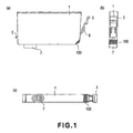
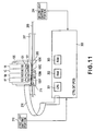
- Figure 1 is a side view (a), front view (b) and bottom view (c) of an ink container which the present invention is applicable to
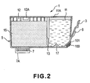
- Figure 2 is a sectional side elevation of the ink container which the present invention is applicable to.
- the front side of the ink container is the side which is faced to the user who is manipulating the ink container (mounting and demounting operation of the ink container), which provides the user with information (by light emission of LED which will be described hereinafter).
- the ink container 1 of this embodiment has a supporting member 3 supported on the lower portion at the front side side thereof.
- the supporting member 3 is made of resin material integrally molded with an outer casing of the ink container 1, and the ink container 1 is displaceable about a portion of the ink container to be supported when the ink container 1 is mounted to the container holder.
- the ink container 1 is provided on its rear side and front side with a first engaging portion 5 and second engaging portion 6, respectively, which are engageable with locking portions provided in a container holder. In this embodiment, they are integral with the supporting member 3. By engagement of the engaging portion 5 and the engaging portion 6 with the locking portions, the ink container 1 is securedly mounted in the ink container 1. The operation during the mounting will be described hereinafter referring to Figure 15.
- the bottom surface of the ink container 1 is provided with an ink supply port 7 for ink supply, which port is connectable with an ink introduction opening of the recording head which will be described hereinafter, by mounting of the ink container 1 to the container holder.
- a base member is provided on the bottom side of the supporting portion of the supporting member 3 at a position where the bottom side and the front side intersect with each other.
- the base member may be in the form of a chip or a plate. In the following description, it is called "substrate" 100.
- Figure 2 figure 2 is a sectional side elevation of the ink container 1.
- An inside of the ink container 1 is divided into an ink reservoir chamber 11 which is provided adjacent the front side where the supporting member 3 and the substrate 100 are provided, and a negative pressure generating member accommodating chamber 12 which is provided adjacent the rear side and which is in fluid communication with an ink supply port 7.
- the ink reservoir chamber 11 and the negative pressure generating member accommodating chamber 12 are in fluid communication with each other through a communication port 13.
- the ink reservoir chamber 11 contains the ink alone in this embodiment, whereas the negative pressure generating member accommodating chamber 12 accommodates an ink absorbing material 15 (negative pressure generating member which is a porous member in this embodiment) made of sponge, fiber aggregate or the like for retaining the ink by impregnation.
- the porous member 15 functions to generate such a negative pressure as is sufficient to provide balance with the force of meniscus formed in the ink ejection nozzle of the recording head to prevent ink leakage from the ink ejection portion to the outside and to permits ink ejection by actuation of the recording head.
- an air vent 12A for introduction of the ambience to ease the negative pressure tending to increase with ink supply into the recording head and to maintain the negative pressure within a predetermined preferable range.
- the ink container 1 shown in Figure 2 may be manufactured by preparing a container body of the ink container 1 on which a substrate which will be described hereinafter is mounted, and then injecting the ink thereinto.
- the ink injection port for carried out such a method may be formed in a top surface of the ink reservoir chamber 11, for example. Then, the injection port may be sealed by a sealing member 11A after t ink injection.
- the sealing member 11A may be dismounted or may be broken to reform an injection port, and the ink is injected using an injector, and then, the reformed injection port may be re-sealed by a sealing member 11A or a substitute member, if necessary.
- opening may be formed at another position in the top surface of the ink reservoir chamber 11, for example, and the ink may be injected through the opening, and then, the opening may be sealed.
- the Embodiments of the manufacturing method for the ink container are in tended to cover such manufacturing methods in which the ink is injected into the ink container containing some responsibility zero amount of the ink.
- the sealing member 7A is detachably mountable in order to prevent of the ink leakage during transportation or storage of the manufactured ink container 1.
- the sealing member 7A may be of any type, such as a capping or typing member or the like, if a predetermined sealing property is provided, and it is removable when the ink container is mounted to the recording head. In the case that ink container is dismounted from the recording head after the start of use, the sealing member 7A and the substitute member may be used to seal the ink supply port 7.
- the internal structure of the ink container 1 is not limited to such a partitioned structure in which the inside is partitioned into the porous member accommodating chamber and the reservoir containing the ink alone.
- the porous member may occupy substantially all of the inside space of the ink container.
- the negative pressure generating means is not limited to the one using the porous member.
- the ink alone is contained in a bladder-like member made of elastic material such as rubber or the like which produces tension in the direction of expanding the volume thereof. In such a case, the negative pressure is generated by the tension in the bladder-like member to retain the ink.
- the ink accommodation space is constructed by a flexible member, and the ink alone is accommodated in the space, wherein a spring force is applied to the flexible member, by which a negative pressure is generated.
- the ink container may be manufactured by injecting the ink in the above-described manner.
- the ink injection may be carried out utilizing the air vent portion, which is provided to introduce the ambience in order to ease the negative pressure tending to increase with ink supply into the recording head and in order to maintain the negative pressure within a predetermined preferable range, as described hereinbefore.
- the bottom portion of the ink reservoir chamber 11 is provided with a portion to be detected 17 at a position opposite to an ink remaining amount detection sensor (which will be described hereinafter) provided in the apparatus side, when the ink container 1 is mounted to the apparatus.
- the ink remaining amount detection sensor is in the form of a photo-sensor comprising a light emitting portion and a light receiving portion.
- the portion to be detected 17 is made of a transparent or semi-transparent material, and when the ink is not contained, the light from the light emitting portion is appropriately reflected toward the light receiving portion (which will be described hereinafter) by providing an inclined surface portion having a configuration, angle or the like for this purpose.
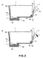
- Figure 3 is schematic side views ((a) and (b)) of a substrate provided on the ink container which the present invention is applicable to.
- Figure 4 is an enlarged view (a) of a major part of the ink container shown in Figure 3, and a view (b) as seen in a direction IVb.
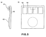
- Figure 5 is a side view (a) and front view (b) of an example of controller substrate mounted to an ink container which the present invention is applicable to.
- the ink container 1 is securedly mounted in or to the holder 150 which is integral with the recording head unit 105 having the recording head 105, by engagements of the first engaging portion 5 and the second engaging portion 6 of the ink container 1 with a first locking portion 155 and a second locking portion 156 of the holder 150, respectively.
- a contact (connector) 152 provided in the holder 150, and a contact in the form of an electrode pad 102 ((b) of Figure 5) provided on a surface of the substrate 100 facing to outside, are electrically contacted to establish electrical connection.
- a surface of the substrate 100 facing inwardly of the ink container 1 is provided with a first light emitting portion 101 such as a LED for emitting visible light and a control unit 103 for controling the light emitting portion, and the control unit 103 controls the light emission of the first light emitting portion 101 in accordance with the electric signal supplied through the connector 152 and the pad 102.
- (a) shows a state in which after the control unit 103 is set in the substrate 100, it is coated with a protecting sealant.
- a memory element for storing information such as a color or the remaining amount of the ink contained in the ink container is employed, it is set at the same place, so that it is coated with the sealant.
- the substrate 100 is disposed at a lower portion of the supporting portion of the supporting member 3 adjacent the portion where the sides of the ink container 1 constituting the bottom side and the front side cross with each other. At this position, an inclined surface is provided between the bottom and front sides of the ink container 1. Therefore, when the first light emitting portion 101 emits light, a part thereof is emitted outwardly from the front side of the ink container 1 along the inclined surface.
- the information relating to the ink container 1 can be directly provided not only to the recording device (and to a host apparatus such as a computer connected thereto) also to the user, by the first light emitting portion 101 alone.
- the light receiving portion is disposed at a position for receiving the light emitted in an upper right direction in the Figure adjacent an end of a scanning range of the carriage for carrying the holder 150, and at the timing when the carriage comes to the position, the light emission of the first light emitting portion 101 is controlled, by which the recording device side can obtain predetermined information relating to the ink container 1 on the basis of a content of the light received by the light receiving portion.
- the predetermined information of the ink container (liquid container) 1 includes at least one of properness of the mounting state of the ink container 1 (i.e. whether the mounting is mounting or not), properness of the position of mounting of the ink container 1 (i.e. whether or not the ink container 1 is mounted on the right position in the holder which is determined corresponding to the ink color), and. Sufficiency of the ink remaining amount (i.e. whether the remaining amount of the ink is sufficient or not).
- the information relating to them can be provided by emission or non-emission of the light and/or states of light emission (flickering or the like). The control of the light emission, the manners of providing the information will be described hereinafter in the description of the structure of the control system.
- FIG 4 shows a preferable example of the disposition, the operation of the substrate 100, and the first light emitting portion 101.
- a portion of the ink container 1 as is opposed to the surface of the substrate 100 having the first light emitting portion 101 and the control unit 103 is provided with a space 1A at least along the optical axis, as indicated by the arrow.
- the arrangement and the configuration of the supporting member 3 are so selected that optical axis is not blocked.
- the holder 150 is provided with a hole (or a light transmitting portion) 150H to assure non-blocking of the optical axis.
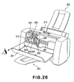
- Figure 6 is a perspective view illustrating an example of a recording head unit having a holder to which the ink container according to the first embodiment is mountable.
- Figure 7 is a schematic side view illustrating an operation of mounting and demounting (a) - (c) of the ink container according to the first embodiment to the holder shown in Figure 14.
- the recording head unit 105 is generally constituted by a holder 150 for detachably holding a plurality (four, in the example shown in the Figure) of ink containers, and a recording head 105 disposed adjacent the bottom side (unshown in Figure 6).
- a holder 150 for detachably holding a plurality (four, in the example shown in the Figure) of ink containers, and a recording head 105 disposed adjacent the bottom side (unshown in Figure 6).
- an ink introduction opening 107 of the recording head disposed adjacent the bottom portion of the holder is connected with the ink supply port 7 of the ink container to establish an ink fluid communication path therebetween.
- An example of usable recording head 105 comprises a liquid passage constituting a nozzle, an electrothermal transducer element provided in the liquid passage.
- the electrothermal transducer element is supplied with electrical pulses in accordance with recording signals, by which thermal energy is applied to the ink in the liquid passage. This causes a phase change of the ink resulting in bubble generation (boiling), and therefore, abrupt pressure rise, by which the ink is ejected from the nozzle.
- the holder 150 When the ink container 1 is mounted to the recording head unit 105, the holder 150 is brought to above the holder 150 ((a) in Figure 7), and a first engaging portion 5 in the form of a projection provided on an ink container rear side is inserted into a first locking portion 155 in the form of a through hole provided in a holder rear side, so that ink container 1 is placed on the inner bottom surface of the holder ((b) of Figure 7).
- the front side upper end of the ink container 1 is pressed down as indicated by arrow P, by which the ink container 1 rotates in the direction indicated by the arrow R about the engaging portion between the first engaging portion 5 and the first locking portion 155, so that front side of the ink container displaces downwardly.
- the supporting member 3 is displaced in the direction of an arrow Q, while a side surface of a second engaging portion 6 provided in the supporting member 3 on the ink container front side is being pressed to the second locking portion 156 provided on the holder front side.
- the above-described uses the principle of "lever" during the mounting process shown in (b) of Figure 7, wherein the engaging portion between the first engaging portion 5 and the first locking portion 155 is a fulcrum, and the front side of the ink container 1 is a power point where the force is applied.
- the connecting portion between the ink supply port 7 and the ink introduction opening 107 is a working point which is located between the power point and the fulcrum, preferably, closer to the fulcrum. Therefore, the ink supply port 7 is pressed against the ink introduction opening 107 with a large force by the rotation of the ink container 1.
- an elastic member such as a filter, an absorbing material, a packing or the like which has a relatively high flexibility is provided to assure an ink communication property to prevent ink leakage there.
- Such structure, arrangement and mounting operation are therefore preferable in that such a member is elastically deformed by the relatively large force.
- the first locking portion 155 engaged with the first engaging portion 5 and the second locking portion 156 engaged with the second engaging portion 6 are effective to prevent the ink container 1 from rising away from the holder, and therefore, the restoration of the elastic member is suppressed, so that member is kept in an appropriately deformed elastically.
- the pad 102 and the connector 152 are made of a relatively rigidity electroconductive material such as metal to assuring satisfy electrical connection property therebetween.
- an excessive contact force therebetween is not preferable from the standpoint of damage prevention and sufficient durability.
- they are disposed at a position as remote as possible from the fulcrum, more particularly, in the neighborhood of the front side of the ink container, in this example, by which the contact force is minimized.
- the pad of the substrate is placed at a position very close to the front side on the bottom side of the ink container.
- it is considered to place the pad of the substrate on the front side of the ink container.
- some limitation is imparted to the disposition of the first light emitting portion 101 on the substrate, which should be selected such that light should properly reach the first light receiving portion 210 and the eyes of the user.
- the pad 102 and the connector 152 approach to each other in a face-to-face fashion in the state immediately before completion of the mounting of the ink container 1, and they abut each other in such a state.
- a large mounting force is required in order to provide a satisfy electrical connection irrespective of the surface conditions of the pad and the connector, with a possible result of excessive force applied to the pad and to the connector.
- the ink leaks out at the connecting portion between the ink supply port 7 and/or the ink introduction opening 107, the leaked ink might reach the pad and/or the connecting portion along the bottom side of the ink container.
- the substrate is disposed at the ink container front side, the disengagement of the ink container from the main assembly of the apparatus may be difficult.
- the substrate 100 is disposed on the inclined surface connecting the bottom side of the ink container 1 with the front side of the ink container 1, namely, at the corner portion therebetween.
- the ink container 1 When the ink container 1 is pressed down toward the mounting completion position where the first engaging portion 5 is engaged with each other, the second engaging portion 6 and the second locking portion 156 are engaged with each other, and there arises a component force (a force sliding the pad 102 on the connector 152) parallel with a surface of the substrate 100 by the urging force. Therefore, a good electrical connection property is provided and assured upon the completion of the mounting of the ink container.
- the electrical connecting portion is at a position high from the bottom side of the ink container, and therefore, the liability of the leaked ink reaching there is small. Furthermore, the optical axes toward the first light receiving portion 210 and toward the eyes of the user can be assured.
- the structure and arrangement of the electrical connecting portion described above is advantageous from the standpoint of assuring the optical path in the case that first light emitting portion 101 is used both for the first light receiving portion, for the eyes of the user, in addition, from the standpoint of the magnitude of the required ink container mounting force, assurance of the electrical contact state and the protection from contamination with the leaked ink.
- the structure of the mounting portion for the ink container in the first embodiment or the modified example is not limited to that shown in Figure 6.
- Figure 8 is a perspective view (a) of another example of the recording head unit for executing the recording operation while being supplied with the ink from the ink container, and a carriage for carrying the recording head unit; and a perspective view wherein the ink container is carried on the carriage.
- the recording head unit 405 of this example is different from those (holder 150) described hereinbefore in that it does not have the holder portion corresponding to the ink container front side, the second locking portion or the connector.
- the recording head unit 405 is similar to the foregoing one in the other respects, the bottom side thereof is provided with an ink introduction opening 107 to be connected with the ink supply port 7.
- the rear side thereof is provided with the first locking portion 155, and the back side is provided with an electrical contact portion (unshown) for signal transmission.
- the carriage 415 is movable along a shaft 417, and is provided with a lever 419 for fixing the recording head unit 405, and an electrical contact portion 418 connected with the electrical contact portion of the recording head.
- the carriage 415 is also provided with a holder portion corresponding to the structure of the ink container front side.
- the second locking portion 156, the connector 152 and the wiring portion 159 to the connector, are provided on the carriage side.
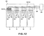
- Figure 9 shows an outer appearance of an ink jet printer 200 to which the ink container described in the foregoing.
- Figure 10 is a perspective view of the printer in which the main assembly cover 201 of Figure 9 is open.
- the printer 200 of this embodiment comprises a main assembly, a sheet discharge tray 203 at the front side of the main assembly, an automatic sheet feeding device (ASF) 202 at the rear side thereof, a main assembly cover 201, and other case portions which cover major parts including a mechanism for scanningly moving the carriage carrying the recording heads and the ink containers and for effecting the recording during the movement of the carriage.
- an operating panel portion 213 which includes a displaying device which in turn displays states of the printer irrespective of whether the main assembly cover is closed or opened, a main switch, and a reset switch.
- the main assembly cover 201 when the main assembly cover 201 is open, the user can see the movable range, the neighborhood thereof which carries the recording head unit 105 and the ink containers 1K, 1Y, 1M and 1C (the ink containers may be indicated by reference numeral "1" only hereinafter for simplicity).
- the main assembly cover 201 when the main assembly cover 201 is opened. A sequence operation is carried out so that carriage 205 is automatically comes to the center position ("container exchanging position", shown in the Figure ), where the user can do the ink container exchanging operation or the like.
- the recording head (unshown) is in the form of a chip mounted to the recording head unit 105, corresponding to the respective inks.
- the recording heads scan the recording material by the movement of the carriage 205, during which the recording heads eject the ink to effect the printing.
- the carriage 205 is slidably engaged with the guiding shaft 207 which extends in the moving direction thereof, is driven by a carriage motor through a drive transmission mechanism.
- the recording heads corresponding to the K, Y, M and C (black, yellow, magenta and cyan) inks eject the inks on the basis of ejection data fed from a control circuit provided in the main assembly side through a flexible cable 206.
- a paper feeding mechanism including a paper feeding roller, a sheet discharging roller and so on to feed the recording material (unshown) fed from the automatic sheet feeding device 202 to the sheet discharge tray 203.
- the recording head unit 105 having an integral ink container holder is detachably mounted on the carriage 205, and the respective ink containers 1 are detachably mounted on the recording head unit 105.
- the recording head unit 105 can be mounted on the carriage 205, and the ink container 1 can be mounted on the recording head unit 105.
- the ink container 1 is, therefore, detachably mountable to the carriage 205 by way of t recording head unit 105.
- the liquid supplying system of the present invention is established.
- the recording head scan the recording material by the above-described movement, during which the recording heads eject the inks onto the recording material to effect the recording on a width of the recording material corresponding to the range of the ejection outlets of the recording head.
- the paper feeding mechanism feeds the recording material through a predetermined distance corresponding to the width. In this manner, the recording is sequentially effected to cover the entire area of the recording material.
- An end portion of the movement range of the recording head by the movement of the carriage there is provided an ejection refreshing unit including caps for capping the sides of the recording heads having the ejection outlets. Therefore, the recording heads move to the position of the refreshing unit at predetermined time intervals, and are subjected to the refreshing process including the preliminary ejections or the like.
- the recording head unit 105 having a holder portion for each ink container 1, is provided with a connector corresponding to each of the ink containers, and the respective connectors are contacted to the pad of the substrate provided on the ink container 1.
- the LED 101 of the ink container 1 is switched on or flickered. This applies to each of the ink containers 1. Adjacent to an end portion which is opposite the position where the refreshing unit is provided, a first light receiving portion 210 having a light receiving element is provided.
- the LEDs 101 of the ink containers 1 pass by the light receiving portion 210 by the movement of the carriage 205, the LEDs 101 are switched on, and the light is received by the first light receiving position 210 so that positions of the ink containers 1 on the carriage 205 can be detected on the basis of the position of the carriage 205 when the light is received.
- the LED 101 of the container is switched on when the ink container 1 is correctly mounted at the container exchange position.
- These controls are executed, similarly to the control for the ink ejection of the recording head, by supplying control data (control signal) to the respective ink containers form the main assembly side control circuit through the flexible cable 206.
- control circuit 300 executes data processing relating to the printer and operation control. More particularly, a CPU 301 carried out processes which will be described hereinafter in conjunction with Figure 17 - Figure 19 in accordance with a program stored in ROM 303. RAM 302 is used as a work area in the process execution of the CPU 301.
- the recording head unit 105 carried on the carriage 205 has recording heads 105K, 105Y, 105M and 105C which have a plurality of ejection outlets for ejecting black (K), yellow (Y), magenta (M) and cyan (C) inks, respectively.
- recording heads 105K, 105Y, 105M and 105C which have a plurality of ejection outlets for ejecting black (K), yellow (Y), magenta (M) and cyan (C) inks, respectively.
- ink containers 1K, 1Y, 1M and 1C are detachably mounted corresponding to the respective recording heads.
- the colors of the ink or the number of the ink container is not limited to those, and the same color inks with different density may be used.
- Each of the ink container 1, as described hereinbefore, is provided with the substrate 100 provided with the LED 101, the display control circuit therefor and the pad (electric contact) or the like.
- the pad on the substrate 100 is contacted to the connector provided corresponding to each of ink containers 1 in the recording head unit 105.
- the connector (unshown) provided in the carriage 205, the control circuit 300 provided in the main assembly side, are electrically connected for transmission of signals through the flexible cable 206. Furthermore, by the mounting of the recording head unit 105 on the carriage 205, the connector of the carriage 205 and the connector of the recording head unit 105 are electrically contacted with each other for signal transmission.
- the signals can be transmitted between the control circuit 300 of the main assembly side and the respective ink containers 1.
- the control circuit 300 can perform the control for turn-on and -off of LED in accordance with the sequence which will be described hereinafter in conjunction with Figure 25 - Figure 27.
- the control of ink ejections of the recording heads 105K, 105Y, 105M and 105C, is carried out similarly through the flexible cable 206, the connector of the carriage 205, the connector of the recording head unit with the signal connection between the driving circuit and so on provided in the recording head, and the control circuit 300 in the main assembly side.
- the control circuit 300 controls the ink ejections and so on for the respective recording heads.
- the first light receiving portion 210 disposed adjacent one of the end portions of the movement range of the carriage 205 receives light from the LED 101 of the ink container 1, and a signal indicative of the event is supplied to the control circuit 300.
- the control circuit 300 responds to the signal to discriminate the position of the ink container 1 in the carriage 205.
- an encoder scale 209 is provided along the movement path of the carriage 205, and the carriage 205 is correspondingly provided with an encoder sensor 211.
- the detection signal of the sensor is supplied to the control circuit 300 through the flexible cable 206, by which the movement position of the carriage 205 is obtained.
- the position information is used for the respective recording head ejection controls, and is used also for light validation process in which the positions of the ink containers are detected, which will be described hereinafter in conjunction with Figure 17.
- a second light emission / receiving portion 214 is provided in the neighborhood of the predetermined position in the movement range of the carriage 205, includes a light emitting element and a light receiving element, and it functions to output to the control circuit 300 a signal relating to an ink remaining amount of each of the ink container 1 carried on the carriage 205.
- the control circuit 300 can detect the ink remaining amount on the basis of the signal.
- Figure 12 figure 20 Figure 20 shows a structure of signal line wiring for signal transmission between the ink container 1 and the flexible cable 206 of the ink jet printer in terms of the substrate 100 of the ink container 1.
- the signal line wiring for the ink container 1 comprises four signal lines in this embodiment, each of them is common for all of four ink containers 1 (bus connection).
- the signal line wiring for the ink containers 1 include four signal lines, namely, a voltage source signal line VDD relating to electric power supply such as for an operation of a control unit 103 for effecting light emission, actuation of the LED 101 in the ink container; a ground signal line GND; a signal line DATA for supplying control signal (control data), the like relating to the process such as turning-on and -off of the LED 101 from the control circuit 300; and a clock signal line CLK therefor.
- Each of the substrates 100 of the ink containers 1 has a controller 103 which is responsive to the signal supplied through the four signal lines, and a LED 101 actuatable in response to the output of the controller 103.
- the ink container has a minimum number of connecting contacts, and with such examples, the LED101 can be controlled, the information of the ink container can be obtained, and/or the information can be obtained or renewed, with a driving timing chart which will be described hereinafter in conjunction with Figures 15 and 16.
- Figure 13 is a circuit diagram showing the details of one embodiment of the substrate on which a controller which the present invention is applicable to is provided. The description will be made with an ink container as the cartridge, an ink as the recording material and the light emitting diode (LED) as the light emitting portion.
- the controlling unit 103 provided in the substrate100A- 100D on the ink container, comprises a semiconductor substrate 120 which has a memory array 103B (information storing portion), LED driver 103C (driver), and an I/O control circuit 103A for controling the memory array 103B and the LED driver 103C.
- the I/O control circuit 103A is responsive to control data fed through the flexible cable 206 from the control circuit 300 of the main assembly side to control the display driving of the LED 101 through the LED driver 103C for notifying operation, the writing of the data in the memory array 103B and the reading of the data.
- Figure 13 is a block diagram, and therefore, the signal connection between the control circuit 300 of the main assembly side and the substrate 100A of the ink container side, are shown in a simplified manner.
- control data fed form a control signal connector 110 in the main assembly side through the flexible cable 206 are not transmitted directly to the substrate100A- 100D on the ink container, but they are transmitted through an electrical contact portion for signal transmission provided in the carriage 203, the electrical contact portion 157 on the recording head unit 105 side, or the like.
- the memory array 103B is in the form of an EEPROM in this embodiment, and is able to store individual information of the ink container, such as information relating to the ink remaining amount in the ink container, the color information of the ink therein, and in addition, manufacturing information such as a number of the ink container, production lot number or the like.
- the color information is written in a predetermined address of the memory array 103B corresponding to the color of the ink stored in the ink container.
- the color information is used as ink container discrimination information (individual information) which will be described hereinafter in conjunction with Figures 15 and 16 to identify the ink container when the data is written in the memory array 103B and is read out therefrom, or when the actuation and deactuation of the LED 101 is controlled for the particular ink container.
- the data written in the memory array 103B or read out of it include, for example, the data indicative of the ink remaining amount.
- the ink container of this embodiment, as described hereinbefore, is provided in the bottom portion with a prism, and when the remaining amount of the ink becomes small, the event can be optically detected by means of the prism.
- the control circuit 300 of this embodiment counts the number of ejections for each of the recording heads on the basis of the ejection data.
- the remaining amount information is written in the memory array 103B of the corresponding ink container, and the information is read out. By doing so, the memory array 103B stores the information of the ink remaining amount in real time.
- the information represents the ink remaining amount with high accuracy since the information is provided with the aid of the prism, too. Also, it is possible to use it to discriminate whether the mounted ink container is a fresh one, or used and then remounted one.
- a LED driver 103C functions to apply a power source voltage to the LED 101 to cause it to emit light when the signal supplied from the I/O control circuit 103A is at a high level. Therefore, when the signal supplied from the I/O control circuit 103A is at a high level, the LED 101 is in the on-state, and when the signal is at a low level, the LED 101 is in the off-state.
- Designated by reference numeral 113 is a contact for connecting an anode side of the LED101 to the LED driver 102C on the semiconductor substrate 120; 115 is a contact for connecting the cathode side of the LED101 to the ground line of the semiconductor substrate 120.
- Designated by reference numeral 114 is a limiting resistor for determining a current supplied to the LED101, and is electrically interposed between the output side of the LED driver 103C and the anode side of the LED114.
- the limiting resistor 114 may be provided in the substrate100A- 100D on the ink container or may be built in the semiconductor substrate 120.
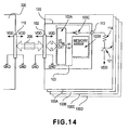
- Figure 14 a circuit diagram of a modified example of the substrate of Figure 13.
- This modified example is different from the example of Figure 13 in the structure for applying the power source voltage to the LED 101, more particularly, the voltage source voltage is supplied from the VDD voltage source pattern provided inside the substrate 100 of the ink container.
- respective elements constituting the controlling unit 103 are built in the semiconductor substrate 120 all together, and the connecting contact means connected to the LED101 is only the connecting contact 113. Reduction of the number of the connecting contacts by only one is significantly influential to the area occupied by the semiconductor substrate 120, so that cost reduction of the semiconductor substrate 120 is significant.
- start code plus color information, control code, address code, data code are supplied in the order named from the control circuit 300 in the main assembly side through the signal line DATA ( Figure 12) to the I/O control circuit 103A in the controller 103 of the ink container 1 in synchronism with the clock signal CLK.
- the start code signal in the start code plus color information indicates the begining of the series of the data signals, and the color information signal is effective to identify the particular ink container which the series of data signal are related to.
- the color information has a code corresponding to each colors of the ink, K, C, M and Y.
- the I/O control circuit 103A compares the color information indicated by the code with the color information stored in the memory array 103B of the ink container per se. Only if they are the same, the subsequent data are taken in, and if not, the subsequent data are ignored. In this embodiment, the color information corresponding to the information supplied from the recording device.
- the control modes of this embodiment include OFF and ON codes for actuation and deactuation of the LED which will be described hereinafter, and READ and WRITE codes for for access to the memory array, that is, for reading out of the memory array and writing therein.
- the WRITE code follows the color information code for identifying the ink container.
- the next code, i.e., the address code indicates an address in the memory array in which the data are to be written in
- the last code i.e., the data code indicates the content of information to be written in.
- these codes correspond to the commands from the recording device.
- the content indicated by the control code is not limited to the example described above, and, for example, control codes for verification command and/or continuous reading command may be added.
- the structure of the data signal is the same as in the case of the writing operation.
- the code of the start code plus color information is taken by the I/O control circuit 103A of all of the ink containers, similarly to the case of the writing operation, and the subsequent data signal are taken in only by the I/O control circuit 103A of the ink container having the same color information. What is different is that.
- the read data are outputted in synchronizm with rising of the first clock (13th clock in Figure 23) after the address is designated by the address code.
- the I/O control circuit 103A effects control to prevent interference of the read data with another input signal even though the data signal contacts of the ink containers are connected to the common (one) data signal line.
- the data signal of the start code plus color information is first sent to the I/O control circuit 103A through the signal line DATA from the main assembly side, similarly to the foregoing.
- the right ink container is identified on the basis of the color information, and the actuation and deactuation of the LED 101 by the control code fed subsequently, are effected only for the identified ink container.
- the control codes for the actuation and the deactuation include one of ON code and OFF code which are effective to actuate and deactuate the LED 101, respectively.
- the I/O control circuit 103A when the control code indicates ON, the I/O control circuit 103A outputs an ON signal to the LED driver 103C, as described hereinbefore in conjunction with Figure 13, the output state is continuously maintained thereafter. On the contrary, when the control code indicates OFF, the I/O control circuit 103A outputs an OFF signal to the LED driver 103C, and the output state is continuously maintained thereafter.
- the actual timing for the actuation or deactuation of the LED 101 is after 7th clock of the clock CLK for each of the data signals.
- the black (K) ink container which the leftmost data signal designates is first identified, and then, the LED 101 of the black ink K container is switched on. Then, the color information of the second data signal indicates magenta ink M, and the control code indicates actuation, and therefore, the LED 101 of the ink M container is switched on while the LED 101 of the ink K container is kept in ON state.
- the control code of the third data signal means instruction of deactuation, and only the LED 101 of the ink K container is deactuated.
- the flickering control of the LED is accomplished by the control circuit 300 of the main assembly side sending repeated actuation and deactuation control codes alternately for the identified ink container.
- the cyclic period of the flickering can be determined by selecting the cyclic period of the alternating control codes.
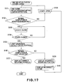
- Figure 17 is a flow chart illustrating control processes relating the mounting and demounting of the ink container according to the embodiment of the present invention, and particularly shows the actuation and deactuation control for the LED 101 of each of the ink containers 1K, 1Y, 1M and 1C by the control circuit 300 provided in the main assembly side.
- the process shown in Figure 17 starts in response to the user opening the main assembly cover of the printer 201 ( Figure s9, 10) which is detected by a predetermined sensor.
- the ink container is mounted or demounted by step S101.
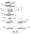
- Figure 18 is a flow chart of a mounting and demounting process of the ink container.
- the carriage 205 moves at step S201, and the information of the state of ink container (individual information thereof) carried on the carriage 205 is obtained.
- the information of the state to be obtained here is an ink remaining amount or the like which is read out of the memory array 103B together with the number of the ink container.
- the discrimination is made as to whether the carriage 205 reaches the ink container exchange position having been described in conjunction with Figure 9 or not.
- step S203 is executed for ink container mounting confirmation control.
- FIG. 19 is a flow chart showing in detail the mounting confirmation control.
- a parameter N indicative of the number of the ink container carried on the carriage 205 is set, and a flag F (k) for confirmation of light emission of the LED correspondingly to the number of the ink container, is initialized.
- N is set to 4 since the number of the ink containers is 4 (K, C, M, Y).
- step S302 a variable An of the flag relating to the order of mounting discrimination for the ink container is set to "1", and in step S303, the mounting confirmation control is effected for the Ath ink container.
- the contact 152 of the holder 150 and the contact 102 of the ink container are contacted with each other by the user mounting the ink container to the right position in the holder 150 of the recording head unit 105, by which the control circuit 300 of the main assembly side, as described hereinbefore, identifies the ink container by the color information (individual information for the ink container), and the color information stored in the memory array 103B of the identified container is sequentially read out.
- the color information for the identification is not used for the already read out one or ones.
- the discrimination is also made as to whether or not the read color information is different from the color information already read out after the start of this process.
- step S304 if the color information have been able to read out, the color information has been different from the already read out piece or pieces of information, it is then discriminated that ink container of the color information is mounted as the A-th ink container. Otherwise, it is discriminated that A-th ink container is not mounted.
- the "A-th" represents only the order of discrimination of the ink container, does not represent the order indicative of the mounted position of the ink container.
- the flag F (A) is set to "0" in step S311.
- an abnormality state is returned to the processing routine of Figure 18 in step S312 since there is a possibility that user has closed the cover although one of some of the ink containers are not mounted or are not properly mounted. Then, this process operation is completed.
- step S309 discriminates that not all of the LEDs are switched on, the lighted on LED or LEDs are flickered to notify the user of the fact the there is at least one unmounted or incompletely mounted (the contact 152 of the holder 150 and the contact 102 of the ink container 1 are not electrically contacted to each other) ink container.
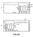
- FIG. 20 shows a state (a) in which all of the ink containers are correctly mounted at correct positions, and therefore, the LEDs are all switched on, respectively.
- step S203 the discrimination is made as to whether or not the control is normally completed, namely, whether or not the ink containers are properly mounted, in step S204. If the mountings are discriminated as being normal, the displaying device ( Figure 9 and Figure 10) in the operating portion 213 is lighted green, for example, and in step S205, a normal ending is executed at step S206, and the operation returns to the example shown in Figure 17.
- the displaying device in the operating portion 213 is flickered orange, for example, in step S207, and the abnormality ending is carried out, and then, the operation returns the processing routine shown in Figure 17.
- the mounting abnormality display is also effected on the display of the PC simultaneously.
- step S101 when the ink container seating process of step S101 is completed, the discrimination is made as to whether or not the mounting or demounting process is properly completed in step S102. If the abnormality is discriminated, the process operation waits for the user to open the main assembly cover 201, and in response to the opening of the cover 201, the process of the step S101 is started, so that process described in conjunction with Figure 18 is repeated.
- step S102 When the proper mounting or demounting process is discriminated in step S102, the process waits for the user to close the main assembly cover 201 in step S103, and the discrimination is made as to whether or not the cover 201 is closed or not in step S104. If the result of the discrimination is affirmative, the operation proceeds to light validation process of step S105. In this case, if the closing of the main assembly cover 201 is detected as shown by (b) in Figure 20, the carriage 205 moves to the position for light validation, and the LEDs 101 of the ink containers are deactuated.
- the light validation process is intended to discriminate whether or not the properly mounted ink containers are mounted at the correct positions, respectively.
- the structures of the ink containers are not such that configurations thereof are made peculiar depending on the colors of the ink contained therein for the purpose of preventing the ink containers from being mounted at wrong positions. This is for the simplicity of manufacturing of the ink container bodies. Therefore, there is a possibility that ink containers are mounted at wrong positions.
- the light validation process is effective to detect such wrong mounting and to notify the user of the event. By this, the efficiency and low cost of the ink container manufacturing are accomplished since it is not required to make the configurations of the ink containers different from each other depending on the colors of the ink.
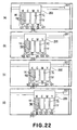
- Figure 21 illustrates the light validation process (a) - (d).
- Figure 22 also illustrates the light validation process (a) - (d).
- the movable carriage 205 first starts moving from the lefthand side to the righthand side in the Figure toward the first light receiving portion 210.
- a signal for actuating the LED 101 of the yellow ink container is outputted in order to switch it on for a predetermined time duration, by the control having been described in conjunction with Figure 16.
- the first light receiving portion 210 receives the light from the LED 101, so that control circuit 300 discriminates that ink container 1Y is mounted at the correct position.
- a magenta ink container 1M is erroneously mounted at a position for a cyan ink container 1C, as shown by (c) in Figure 20, the LED 101 of the ink container 1M which is opposed to the first light receiving portion 210 is not actuated, but the ink container 1C mounted at another position is switched on.
- the light validation process with the control circuit 300 described above is effective to identify the ink container or ink containers not mounted at the correct position. If the mounting position does not have the correct ink container mounted thereto, the color of the ink container erroneously mounted there can be identified by sequentially actuating the LEDs of the other three color ink containers.
- the discrimination is made as to whether or not the light validation process is properly completed or not in step S106.
- the displaying device in the operating portion 213 is lighted up green, for example, in step S107, and the process ends.
- the displaying device in the operating portion 213 is flickered orange at step S109, and the LED 101 of the ink container which is not mounted at the correct position and which has been identified in the step S105 is flickered or switched on in step S105.
- the user opens the main assembly cover 201, the user is notified of the ink container which is not mounted at the correct position, so that user is prompted to remount it to the correct position.
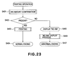
- Figure 23 figure 23q is a flow chart illustrating a recording process according to the embodiment of the present invention.
- the ink remaining amount is first checked in step S401.
- an amount of printing is determined from the printing data of the job for which the printing is going to be effected, and the comparison is made between the determined amount and the remaining amount of the ink container to check whether the remaining amount is sufficient or not (confirmation process).
- the ink remaining amount is the amount detected by the control circuit 300 on the basis of the counting.
- step S402 the discrimination is made as to whether the remaining ink amount is sufficient to the printing or not, on the basis of the confirmation process. If the ink amount is sufficient, the operation goes to the printing in step S403, and the displaying device of the operating portion 213 is lighted green at step S404 (normal ending). On the other hand, if the result of the discrimination at the step S402 indicates a shortage of the ink, the displaying device of the operating portion 213 is flickered orange in the step S405, and in step S406, the LED 101 of the ink container 1 containing the insufficient amount of the ink is flickered or switched on (abnormal ending).
- the user can confirm the information relating to the ink container by the display function provided in the ink container per se.
- the structure of the foregoing embodiments not only the remaining service life of the cartridge and the timing of cartridge exchange, but also the information indicative of the properness of the mounting can be notified to the user utilizing the light emitting portion.
- the manner of utilization of the light emitting portion is wide ranging, and the possibility of utilization is wide.
- the first engaging portion 5 provided on the ink container rear side is inserted into the first locking portion 155 provided at the rear side of the holder, and the ink container 1 is rotated about the rotational pivot which is the inserted portion, while pushing the ink container front side down.
- the position of the substrate 100 is, as described hereinbefore, the front side which is away from the rotational pivot, and the first light receiving portion 210, and the first light emitting portion 101 for directing the light toward the first light receiving portion 210, toward the user's eyes are integral with the substrate 100, accordingly.
- the preferable position of the substrate and the position required by the light emitting portion are different from each other, depending on the structures of the ink container and/or the mounting portion thereof.
- the substrate and the light emitting portion may be disposed at proper positions. In other words, they are not necessarily integral with each other.
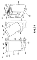
- Figure 24 illustrates structures of an ink container and a mounting portion thereof according to another embodiment of the present invention ((a) - (c)).
- the ink container 501 of this embodiment of the present invention is provided on the top side adjacent the front side with a substrate 600 which has a light emitting portion 601 such as LED, which has a pad 602 at the top rear portion.
- a light emitting portion 601 such as LED
- the light is emitted toward the front side.
- a light receiving portion 620 is disposed at a position for receiving the light directed leftward in the Figure adjacent an end of a scanning range of the carriage.
- the light emitting portion 601 is controlled, so that recording device side can obtain predetermined information relating to the ink container 501 from the content of the light received by the light receiving portion.
- the light emitting portion 601 is controlled, by which the user is able to see the state of lightening so that predetermined information relating to the ink container 501 can be recognized by the user.
- the recording head unit 605 comprises a holder 650 for detachably holding a plurality of ink containers (two, in the example of the Figure ), a recording head 605 ' provided at the bottom side thereof.
- a holder 650 for detachably holding a plurality of ink containers (two, in the example of the Figure ), a recording head 605 ' provided at the bottom side thereof.
- an ink introduction opening 607 of the recording head side located in the inner bottom portion of the holder is connected with an ink supply port 507 located in the bottom portion of the ink container, so that ink fluid communication path is established therebetween.
- the holder 650 is provided on a rear side thereof with a locking portion 656 for locking the ink container 501 at the complete mounting position with the engaging portion 655 (rotational center) at the front side.
- the user brings the ink container 501 to the front side of the holder 650, as shown by (b) in Figure 24, presses the lower edge portion of the ink container rear side to the rear side of the holder 650 to bring the ink container front side into engagement with the engaging portion 655 of the holder 650.
- the upper portion of the front side of the ink container 501 is pressed toward the rear side, by which the ink container 501 is mounted in the holder while rotating in the direction indicated by an arrow about the engaging portion 655.
- ink container 501 which has been completely mounted, wherein the ink supply port 507 and the ink introduction opening 607 are connected to each other, and the pad 602 and the connector 652 are connected with each other.
- the pad 602 and the connector 652 are located at a position as far as possible from the rotational center upon the mounting operation, and immediately before completion of the mounting of the ink container 501, they are contacted to each other so that satisfy electrical connection property is established therebetween upon the completion of mounting.
- the structures of the engaging portion 655 of the holder 650 and the locking portion 656 and the corresponding structure of the ink container 501 side may be properly determined by one skilled in the art.
- the substrate 600 is provided on the top surface of the ink container 501, and extends in parallel with the top surface, but this is not limiting, and it may be inclined as in the first embodiment.
- the holder 650 and the structural members relating to it is not necessarily provided in the head unit.
- Figure 25 shows a modified example of Figure 24 structure, and shows two recording head units (liquid containing cartridges) each of which comprises an ink container 501 and a recording head 605 ' which are integral with each other.
- one of the units is a cartridge for black ink, and the other is a cartridge for yellow, magenta and cyan inks.
- the holder 650 may be provided with similar structures corresponding to such a structure.
- the control circuit for the light emitting portion 601 disposed on the front side may be provided at a proper position on the head unit.
- a control circuit is provided on the driving circuit substrate having an integral recording head 605 ', and the wiring is extended to the light emitting portion 601.
- a driving circuit for the recording head 605 ' and the control circuit for the light emitting portion 601 are connected with an electrical contact portion on the carriage through an unshown electrical contact portion.
- Figure 26 is a perspective view of a printer to which the ink container according to said another embodiment of the present invention.
- the same reference numerals as in Embodiment shown in Figure 9 and Figure 10 are assigned to the elements having the corresponding functions in this embodiment, and the detailed description thereof is omitted for simplicity.
- an ink container 501K containing black ink, and an ink containers 501CMY having integral accommodating chambers containing cyan, magenta and yellow inks separately, are mounted in the holder of the recording head unit 605 on the carriage 205.
- the LED 601 is provided as a separate member from the substrate, and the user can see the LEDs 601 at the front side when the ink container is mounted at the exchange position.
- a light receiving portion 210 is provided in the neighborhood of one of the end portions of the movement range of the carriage 205.
- a liquid container detachably mountable to a recording apparatus to which a plurality of liquid containers are detachably mountable wherein the recording apparatus includes apparatus electrical contacts corresponding to the liquid containers, respectively, photoreceptor means for receiving light, and an electric circuit connected with a line which is commonly connected with the apparatus electrical contacts, the liquid container includes a container electrical contact electrically connectable with one of the apparatus contacts; an information storing portion capable of storing at least individual information relating to the liquid container; a light emitting portion; an actuating portion for actuating the light emitting portion; a controller for controlling access to the information storing portion and/or actuation of the light emitting portion by the driver in response to individual information supplied from the recording device and reception of a command from the recording device.
Landscapes
- Ink Jet (AREA)
- Containers And Packaging Bodies Having A Special Means To Remove Contents (AREA)
- Manufacturing Of Printed Wiring (AREA)
- Packaging Of Annular Or Rod-Shaped Articles, Wearing Apparel, Cassettes, Or The Like (AREA)
Priority Applications (6)
| Application Number | Priority Date | Filing Date | Title |
|---|---|---|---|
| PL11150832T PL2319694T3 (pl) | 2003-12-26 | 2004-12-22 | Pojemnik na ciecz, system dostarczania cieczy, sposób jego wytwarzania, płytka obwodu dla niego oraz kartridż zawierający ciecz |
| EP11154693.3A EP2322351B1 (fr) | 2003-12-26 | 2004-12-22 | Réservoir de liquide et imprimante |
| EP11150832.1A EP2319694B1 (fr) | 2003-12-26 | 2004-12-22 | Réservoir de liquide, système d'alimentation de liquide, sa méthode de fabrication, sa carte de circuit et cartouche contenant du liquide |
| DK11150832.1T DK2319694T3 (da) | 2003-12-26 | 2004-12-22 | Væskebeholder, væsketilførselssystem, fremgangsmåde til fremstilling deraf, printplade dertil samt væske-indeholdende patron |
| EP10195661A EP2319693B1 (fr) | 2003-12-26 | 2004-12-22 | Réservoir de liquide, système d'alimentation de liquide, sa méthode de fabrication, sa carte de circuit et cartouche contenant du liquide |
| DK11154693.3T DK2322351T3 (en) | 2003-12-26 | 2004-12-22 | Liquid Container and printer |
Applications Claiming Priority (4)
| Application Number | Priority Date | Filing Date | Title |
|---|---|---|---|
| JP2003435942 | 2003-12-26 | ||
| JP2003435942 | 2003-12-26 | ||
| JP2004319751A JP4298629B2 (ja) | 2003-12-26 | 2004-11-02 | インクジェット記録装置 |
| JP2004319751 | 2004-11-02 |
Related Child Applications (6)
| Application Number | Title | Priority Date | Filing Date |
|---|---|---|---|
| EP10195661A Division-Into EP2319693B1 (fr) | 2003-12-26 | 2004-12-22 | Réservoir de liquide, système d'alimentation de liquide, sa méthode de fabrication, sa carte de circuit et cartouche contenant du liquide |
| EP11154693.3A Division EP2322351B1 (fr) | 2003-12-26 | 2004-12-22 | Réservoir de liquide et imprimante |
| EP11154693.3A Division-Into EP2322351B1 (fr) | 2003-12-26 | 2004-12-22 | Réservoir de liquide et imprimante |
| EP11150832.1A Division-Into EP2319694B1 (fr) | 2003-12-26 | 2004-12-22 | Réservoir de liquide, système d'alimentation de liquide, sa méthode de fabrication, sa carte de circuit et cartouche contenant du liquide |
| EP10195661.3 Division-Into | 2010-12-17 | ||
| EP11150832.1 Division-Into | 2011-01-13 |
Publications (4)
| Publication Number | Publication Date |
|---|---|
| EP1547784A2 true EP1547784A2 (fr) | 2005-06-29 |
| EP1547784A3 EP1547784A3 (fr) | 2008-10-22 |
| EP1547784B1 EP1547784B1 (fr) | 2011-02-23 |
| EP1547784B2 EP1547784B2 (fr) | 2018-01-17 |
Family
ID=34554892
Family Applications (4)
| Application Number | Title | Priority Date | Filing Date |
|---|---|---|---|
| EP11150832.1A Expired - Lifetime EP2319694B1 (fr) | 2003-12-26 | 2004-12-22 | Réservoir de liquide, système d'alimentation de liquide, sa méthode de fabrication, sa carte de circuit et cartouche contenant du liquide |
| EP10195661A Revoked EP2319693B1 (fr) | 2003-12-26 | 2004-12-22 | Réservoir de liquide, système d'alimentation de liquide, sa méthode de fabrication, sa carte de circuit et cartouche contenant du liquide |
| EP11154693.3A Expired - Lifetime EP2322351B1 (fr) | 2003-12-26 | 2004-12-22 | Réservoir de liquide et imprimante |
| EP04030458.6A Expired - Lifetime EP1547784B2 (fr) | 2003-12-26 | 2004-12-22 | Réservoir de liquide, système d'alimentation de liquide, sa méthode de fabrication, sa carte de circuit et cartouche contenant du liquide |
Family Applications Before (3)
| Application Number | Title | Priority Date | Filing Date |
|---|---|---|---|
| EP11150832.1A Expired - Lifetime EP2319694B1 (fr) | 2003-12-26 | 2004-12-22 | Réservoir de liquide, système d'alimentation de liquide, sa méthode de fabrication, sa carte de circuit et cartouche contenant du liquide |
| EP10195661A Revoked EP2319693B1 (fr) | 2003-12-26 | 2004-12-22 | Réservoir de liquide, système d'alimentation de liquide, sa méthode de fabrication, sa carte de circuit et cartouche contenant du liquide |
| EP11154693.3A Expired - Lifetime EP2322351B1 (fr) | 2003-12-26 | 2004-12-22 | Réservoir de liquide et imprimante |
Country Status (19)
| Country | Link |
|---|---|
| US (1) | US7237881B2 (fr) |
| EP (4) | EP2319694B1 (fr) |
| JP (1) | JP4298629B2 (fr) |
| KR (1) | KR100754038B1 (fr) |
| CN (1) | CN1636744A (fr) |
| AT (1) | ATE499213T1 (fr) |
| AU (1) | AU2004242556B2 (fr) |
| BR (1) | BRPI0405830A (fr) |
| CA (2) | CA2759022C (fr) |
| CY (1) | CY1114557T1 (fr) |
| DE (1) | DE602004031499D1 (fr) |
| DK (2) | DK2322351T3 (fr) |
| ES (3) | ES2401962T3 (fr) |
| MX (1) | MXPA04012677A (fr) |
| PL (1) | PL2319694T3 (fr) |
| PT (1) | PT2319694E (fr) |
| SG (3) | SG113034A1 (fr) |
| SI (1) | SI2319694T1 (fr) |
| TW (1) | TWI295631B (fr) |
Cited By (3)
| Publication number | Priority date | Publication date | Assignee | Title |
|---|---|---|---|---|
| CN105082773A (zh) * | 2011-12-30 | 2015-11-25 | 珠海艾派克微电子有限公司 | 一种可拆装地安装到打印机上的墨盒及墨盒上的存储芯片 |
| WO2019074132A1 (fr) * | 2017-10-13 | 2019-04-18 | Canon Kabushiki Kaisha | Élément comprenant une électrode en pastille, cartouche d'encre, appareil d'enregistrement |
| RU2759741C2 (ru) * | 2017-10-13 | 2021-11-17 | Кэнон Кабусики Кайся | Элемент, включающий в себя электрод с плоской контактной поверхностью, чернильный картридж, записывающее устройство |
Families Citing this family (63)
| Publication number | Priority date | Publication date | Assignee | Title |
|---|---|---|---|---|
| AUPQ439299A0 (en) | 1999-12-01 | 1999-12-23 | Silverbrook Research Pty Ltd | Interface system |
| MXPA04012681A (es) * | 2003-12-26 | 2005-07-01 | Canon Kk | Recipiente para liquido y sistema de suministro de liquido. |
| JP4058436B2 (ja) | 2003-12-26 | 2008-03-12 | キヤノン株式会社 | インク収納容器 |
| JP3793216B2 (ja) * | 2003-12-26 | 2006-07-05 | キヤノン株式会社 | 液体収納容器、該容器を備える液体供給システム、前記容器の製造方法、前記容器用回路基板および液体収納カートリッジ |
| JP4058434B2 (ja) | 2003-12-26 | 2008-03-12 | キヤノン株式会社 | インク収納容器、該容器の製造方法およびプリンタシステム |
| JP4047328B2 (ja) * | 2004-12-24 | 2008-02-13 | キヤノン株式会社 | 液体収納容器、該容器を用いる液体供給システムおよび記録装置、並びに前記容器用回路基板 |
| JP2006181717A (ja) * | 2004-12-24 | 2006-07-13 | Canon Inc | 液体収納容器、該容器を用いる液体供給システムおよび記録装置、前記容器用回路モジュールおよび基板、並びに液体収納カートリッジ |
| US7517046B2 (en) * | 2005-05-09 | 2009-04-14 | Silverbrook Research Pty Ltd | Mobile telecommunications device with printhead capper that is held in uncapped position by media |
| US7284921B2 (en) | 2005-05-09 | 2007-10-23 | Silverbrook Research Pty Ltd | Mobile device with first and second optical pathways |
| JP4898147B2 (ja) * | 2005-06-01 | 2012-03-14 | キヤノン株式会社 | インクタンク |
| US7604317B2 (en) * | 2005-06-21 | 2009-10-20 | Canon Kabushiki Kaisha | Recording apparatus capable of checking positions of ink containers, and method for checking the positions |
| JP4649274B2 (ja) * | 2005-06-21 | 2011-03-09 | キヤノン株式会社 | 位置検出方法 |
| JP4659530B2 (ja) * | 2005-06-24 | 2011-03-30 | キヤノン株式会社 | インクタンクホルダおよびインクジェット記録ヘッドカートリッジ |
| CN2832527Y (zh) * | 2005-08-30 | 2006-11-01 | 珠海纳思达电子科技有限公司 | 一种分体式发光墨盒 |
| JP4697434B2 (ja) * | 2006-02-22 | 2011-06-08 | セイコーエプソン株式会社 | キャリッジおよび該キャリッジを備える記録装置 |
| US8240359B2 (en) * | 2006-04-17 | 2012-08-14 | Gerald Garrett | Liquid storage and cooling computer case |
| JP4125329B2 (ja) * | 2006-05-19 | 2008-07-30 | キヤノン株式会社 | 液体収納容器、および該容器を備える液体供給システム |
| JP4942161B2 (ja) | 2006-06-30 | 2012-05-30 | キヤノン株式会社 | 液体収納容器およびインクジェット記録装置 |
| ATE499215T1 (de) | 2008-03-31 | 2011-03-15 | Canon Kk | Tintenbehälter und tintenstrahlaufzeichnungssystem |
| US8160473B2 (en) * | 2008-12-08 | 2012-04-17 | Static Control Components, Inc. | Imaging apparatus and methods |
| US8657396B2 (en) * | 2010-03-02 | 2014-02-25 | Canon Kabushiki Kaisha | Ink jet printing apparatus |
| JP5565029B2 (ja) * | 2010-03-29 | 2014-08-06 | セイコーエプソン株式会社 | 液体容器および液体消費装置 |
| JP5246196B2 (ja) | 2010-03-30 | 2013-07-24 | ブラザー工業株式会社 | インクジェット記録装置 |
| JP5720148B2 (ja) | 2010-09-03 | 2015-05-20 | セイコーエプソン株式会社 | 印刷材カートリッジ、及び、印刷材供給システム |
| JP5569475B2 (ja) * | 2010-09-03 | 2014-08-13 | セイコーエプソン株式会社 | 液体収容容器、及び、液体噴射装置 |
| JP4963513B2 (ja) * | 2010-11-08 | 2012-06-27 | キヤノン株式会社 | 記録装置 |
| JP5828682B2 (ja) * | 2011-06-06 | 2015-12-09 | キヤノン株式会社 | 液体吐出ヘッドの製造方法 |
| JP5887748B2 (ja) | 2011-07-28 | 2016-03-16 | ブラザー工業株式会社 | 印刷装置 |
| JP5880286B2 (ja) | 2011-08-24 | 2016-03-08 | セイコーエプソン株式会社 | 液体容器 |
| JP2013049168A (ja) | 2011-08-30 | 2013-03-14 | Brother Industries Ltd | 印刷流体カートリッジ及び記録装置 |
| JP5899714B2 (ja) | 2011-08-31 | 2016-04-06 | ブラザー工業株式会社 | 印刷装置システム、並びに、それに用いられる接続機器及び印刷装置 |
| CN102950901B (zh) * | 2011-12-30 | 2015-06-03 | 珠海纳思达企业管理有限公司 | 一种喷墨墨盒组及其装机检测方法 |
| US8297739B1 (en) | 2012-03-02 | 2012-10-30 | Seiko Epson Corporation | Cartridge and printing material supply system |
| CN103204006B (zh) | 2012-01-12 | 2017-04-26 | 精工爱普生株式会社 | 印刷装置、以及印刷材料供应系统 |
| US8708469B2 (en) | 2012-01-12 | 2014-04-29 | Seiko Epson Corporation | Cartridge and printing material supply system |
| UA111500C2 (uk) * | 2012-01-12 | 2016-05-10 | Сейко Епсон Корпорейшн | Картридж і система подачі друкувального матеріалу |
| US8915582B2 (en) | 2012-01-12 | 2014-12-23 | Seiko Epson Corporation | Cartridge and printing material supply system |
| CA2860539C (fr) | 2012-01-12 | 2017-03-28 | Seiko Epson Corporation | Systeme d'alimentation pour cartouche et materiau d'impression |
| JP6060544B2 (ja) | 2012-05-23 | 2017-01-18 | セイコーエプソン株式会社 | 液体収容体、及び、収容体ユニット |
| EP2837499B1 (fr) * | 2012-05-23 | 2019-10-16 | Seiko Epson Corporation | Cartouche et élément d'étanchéité |
| US9061512B2 (en) | 2012-05-23 | 2015-06-23 | Seiko Epson Corporation | Cover and liquid container |
| US8894184B2 (en) | 2012-05-23 | 2014-11-25 | Seiko Epson Corporation | Cover and liquid container |
| DE102012104592A1 (de) | 2012-05-29 | 2013-12-05 | Tigerline Gmbh | Flüssigkeitsbehälter und Verfahren zu dessen Betrieb sowie Ausgabeeinrichtung mit Flüssigkeitsbehälter |
| JP6048004B2 (ja) | 2012-07-23 | 2016-12-21 | セイコーエプソン株式会社 | カートリッジ |
| US10384454B2 (en) | 2012-07-23 | 2019-08-20 | Seiko Epson Corporation | Refilled cartridge and method for manufacturing refilled cartridge |
| JP6069964B2 (ja) | 2012-07-23 | 2017-02-01 | セイコーエプソン株式会社 | カートリッジの製造方法、注入キット、及び、注入装置 |
| US9776418B2 (en) | 2012-07-23 | 2017-10-03 | Seiko Epson Corporation | Method and apparatus for manufacturing cartridge |
| CN103832077B (zh) | 2012-11-22 | 2016-02-03 | 珠海艾派克微电子有限公司 | 墨盒芯片的控制方法、墨盒芯片以及墨盒 |
| CN103895359B (zh) * | 2012-12-27 | 2016-03-23 | 珠海纳思达企业管理有限公司 | 墨盒的发光控制方法及装置 |
| WO2014101399A1 (fr) * | 2012-12-27 | 2014-07-03 | 珠海纳思达企业管理有限公司 | Procédé et appareil de commande d'électroluminescence d'un boîtier d'encre |
| CN105377561B (zh) | 2013-07-10 | 2017-12-12 | 惠普发展公司,有限责任合伙企业 | 包括闩手柄和肋的流体容器部 |
| WO2015003514A1 (fr) | 2013-07-11 | 2015-01-15 | 珠海艾派克微电子有限公司 | Puce de cartouche d'encre, cartouche d'encre et bâti adaptatif de cartouche d'encre |
| CN103847237B (zh) * | 2013-12-25 | 2015-09-23 | 珠海艾派克微电子有限公司 | 喷墨成像设备及光检测方法 |
| CN103847238B (zh) * | 2013-12-25 | 2016-04-13 | 珠海艾派克微电子有限公司 | 喷墨成像设备及光检测方法 |
| DE102014000954A1 (de) | 2014-01-24 | 2015-07-30 | 3T Supplies Ag | Tintenpatrone und Tintenpatronensatz |
| JP2015199261A (ja) | 2014-04-08 | 2015-11-12 | ブラザー工業株式会社 | 液体吐出装置 |
| JP6402507B2 (ja) * | 2014-06-25 | 2018-10-10 | セイコーエプソン株式会社 | 流体噴射装置 |
| JP6512774B2 (ja) | 2014-08-25 | 2019-05-15 | キヤノン株式会社 | 液体収納容器の保持部材、プリントヘッドおよびプリンタ |
| JP6447300B2 (ja) | 2015-03-27 | 2019-01-09 | ブラザー工業株式会社 | 液体カートリッジ |
| JP6753054B2 (ja) * | 2015-11-27 | 2020-09-09 | セイコーエプソン株式会社 | 液体収容容器および保護部材 |
| JP2017165037A (ja) * | 2016-03-17 | 2017-09-21 | セイコーエプソン株式会社 | 液体吐出装置及びヘッドユニット |
| EP3565705A4 (fr) | 2017-04-21 | 2020-09-30 | Hewlett-Packard Development Company, L.P. | Imprimante tridimensionnelle |
| CN112147345B (zh) * | 2019-06-28 | 2024-05-17 | 深圳迈瑞生物医疗电子股份有限公司 | 清除残留反应杯的方法、样本分析设备和存储介质 |
Citations (4)
| Publication number | Priority date | Publication date | Assignee | Title |
|---|---|---|---|---|
| JPH04275156A (ja) | 1991-03-01 | 1992-09-30 | Tokyo Electric Co Ltd | インクジェットプリンタ及びこのプリンタに使用されるインクカートリッジ |
| JPH06155769A (ja) | 1992-11-19 | 1994-06-03 | Canon Inc | インクジェット記録装置 |
| JPH0776104A (ja) | 1993-06-30 | 1995-03-20 | Canon Inc | インクジェットプリント装置 |
| US6196670B1 (en) | 1998-11-26 | 2001-03-06 | Seiko Epson Corporation | Printer and ink cartridge attached thereto |
Family Cites Families (42)
| Publication number | Priority date | Publication date | Assignee | Title |
|---|---|---|---|---|
| JPS6032667A (ja) * | 1983-08-02 | 1985-02-19 | Canon Inc | インク残量検出装置 |
| US4849379A (en) * | 1988-01-28 | 1989-07-18 | E. I. Du Pont De Nemours And Company | Dielectric composition |
| DE3880694D1 (de) * | 1988-07-25 | 1993-06-03 | Siemens Ag | Anordnung fuer druckeinrichtungen zur ueberwachung von druckmedium enthaltenden vorratsbehaeltern. |
| US5049898A (en) * | 1989-03-20 | 1991-09-17 | Hewlett-Packard Company | Printhead having memory element |
| DE69034212T2 (de) | 1989-08-05 | 2006-07-13 | Canon K.K. | Tintenstrahlaufzeichnungsgerät und Tintenkassette dafür |
| JP2752793B2 (ja) | 1990-12-10 | 1998-05-18 | キヤノン株式会社 | インクジェット記録装置および該装置用インクタンクカートリッジ |
| JPH05340791A (ja) * | 1992-06-11 | 1993-12-21 | Canon Inc | 液面検知手段およびインクジェット記録装置 |
| JPH0825808B2 (ja) * | 1992-07-16 | 1996-03-13 | スチライト工業株式会社 | 炭酸水素化合物による耐火被覆材 |
| CA2272165C (fr) | 1992-07-31 | 2003-10-14 | Canon Kabushiki Kaisha | Contenant pour liquide dans un appareil enregistreur |
| TW297332U (en) | 1993-01-19 | 1997-02-01 | Canon Kk | Ink jet cartridge, ink jet apparatus and ink container |
| JP3221210B2 (ja) * | 1994-02-07 | 2001-10-22 | 富士ゼロックス株式会社 | インクタンク |
| US5699091A (en) * | 1994-12-22 | 1997-12-16 | Hewlett-Packard Company | Replaceable part with integral memory for usage, calibration and other data |
| US6246484B1 (en) * | 1995-11-22 | 2001-06-12 | Canon Kabushiki Kaisha | Image reading apparatus and information processing apparatus having image reading function |
| US6097405A (en) * | 1996-09-30 | 2000-08-01 | Hewlett-Packard Company | Detection apparatus and method for use in a printing device |
| JPH1161637A (ja) | 1997-08-18 | 1999-03-05 | Canon Inc | 繊維素材及びそのインク接液部材としての用途並びにこれらの製造方法 |
| ES2330915T3 (es) † | 1999-01-25 | 2009-12-17 | Fargo Electronics, Inc. | Metodo y aparato para la comunicacion entre una impresora o una plastificadora y sus suministros. |
| US6312074B1 (en) * | 1999-04-30 | 2001-11-06 | Hewlett-Packard Company | Method and apparatus for detecting fluid level in a fluid container |
| JP2000326604A (ja) | 1999-05-18 | 2000-11-28 | Funai Electric Co Ltd | 印字装置 |
| JP2001010081A (ja) | 1999-06-30 | 2001-01-16 | Canon Inc | インクジェットカートリッジ、インクジェット装置、およびインクジェットカートリッジの製造方法 |
| JP3755755B2 (ja) * | 1999-07-14 | 2006-03-15 | セイコーエプソン株式会社 | インクカートリッジおよびこれを用いたインクジェット式記録装置並びに同装置へのインクカートリッジの装着可否判定方法。 |
| JP2001071522A (ja) | 1999-09-03 | 2001-03-21 | Canon Inc | 液体容器およびプリント装置 |
| JP3492283B2 (ja) | 2000-03-31 | 2004-02-03 | キヤノン株式会社 | 液体容器および記録装置 |
| US6742872B2 (en) | 2000-03-31 | 2004-06-01 | Canon Kabushiki Kaisha | Ink jet recording apparatus and ink tank mounted on such ink jet recording apparatus |
| JP3387890B2 (ja) | 2000-03-31 | 2003-03-17 | キヤノン株式会社 | 液体容器および記録装置 |
| CA2343853A1 (fr) | 2000-04-14 | 2001-10-14 | Muga Mochizuki | Dispositif a semiconducteurs, reservoir d'encre dote de ce dispositif a semiconducteurs, cartouche a jet d'encre, appareil d'enregistrement a jet d'encre, methode de fabrication de ce dispositif a semiconducteurs, systeme de communication, methode de commande de pression, element de memoire, systeme de securite pour appareil d'enregistrement a jet d'encre |
| JP3745199B2 (ja) | 2000-06-16 | 2006-02-15 | キヤノン株式会社 | 立体形半導体素子が配されたインクタンク、および該インクタンクが搭載されるインクジェット記録装置 |
| ATE519598T1 (de) | 2000-06-16 | 2011-08-15 | Canon Kk | Tintenstrahlaufzeichnungsgerät das ein festkörperhalbleiterbauelement verwendet |
| JP3814465B2 (ja) | 2000-06-16 | 2006-08-30 | キヤノン株式会社 | インクジェット記録システム |
| DE60140497D1 (de) † | 2000-11-20 | 2009-12-24 | Seiko Epson Corp | Behälteridentifikation für Aufzeichnungsmaterial |
| JP3697213B2 (ja) | 2001-02-09 | 2005-09-21 | キヤノン株式会社 | 液体収納容器、および液体の撹拌方法 |
| CA2371040A1 (fr) | 2001-02-09 | 2002-08-09 | Nobuyuki Hatasa | Contenant a liquide et appareil d'enregistrement |
| CA2379725C (fr) | 2001-04-03 | 2007-06-12 | Seiko Epson Corporation | Cartouche a encre |
| JP2002301829A (ja) | 2001-04-04 | 2002-10-15 | Canon Inc | インクジェット記録装置 |
| JP3596871B2 (ja) | 2001-09-28 | 2004-12-02 | キヤノン株式会社 | 液体収納容器 |
| JP3667283B2 (ja) | 2002-01-25 | 2005-07-06 | キヤノン株式会社 | 液体収納容器 |
| JP4086515B2 (ja) | 2002-02-15 | 2008-05-14 | キヤノン株式会社 | シール部材とそれを用いた接続構造および液体噴射記録ヘッド |
| JP4018422B2 (ja) | 2002-03-29 | 2007-12-05 | キヤノン株式会社 | 液体収納容器、および液体収納容器の識別方法 |
| JP2003300358A (ja) | 2002-04-10 | 2003-10-21 | Canon Inc | カートリッジ装着装置およびプリンタ装置 |
| US7128380B2 (en) | 2002-04-10 | 2006-10-31 | Canon Kabushiki Kaisha | Recording liquid container, ink jet recording apparatus, and cartridge collecting apparatus |
| JP3754954B2 (ja) | 2002-11-27 | 2006-03-15 | キヤノン株式会社 | 液体収容容器およびインクジェット記録装置 |
| JP2004358913A (ja) | 2003-06-06 | 2004-12-24 | Canon Inc | インクタンクおよびインクタンクホルダー |
| JP2005028779A (ja) | 2003-07-07 | 2005-02-03 | Canon Inc | インクタンクおよびインクタンクホルダー |
-
2004
- 2004-11-02 JP JP2004319751A patent/JP4298629B2/ja not_active Expired - Fee Related
- 2004-12-15 MX MXPA04012677A patent/MXPA04012677A/es active IP Right Grant
- 2004-12-21 CA CA2759022A patent/CA2759022C/fr not_active Expired - Fee Related
- 2004-12-21 US US11/016,757 patent/US7237881B2/en not_active Expired - Lifetime
- 2004-12-21 CA CA2490744A patent/CA2490744C/fr not_active Expired - Fee Related
- 2004-12-22 EP EP11150832.1A patent/EP2319694B1/fr not_active Expired - Lifetime
- 2004-12-22 SI SI200432109T patent/SI2319694T1/sl unknown
- 2004-12-22 DK DK11154693.3T patent/DK2322351T3/en active
- 2004-12-22 ES ES10195661T patent/ES2401962T3/es not_active Expired - Lifetime
- 2004-12-22 SG SG200407932A patent/SG113034A1/en unknown
- 2004-12-22 DE DE602004031499T patent/DE602004031499D1/de not_active Expired - Lifetime
- 2004-12-22 EP EP10195661A patent/EP2319693B1/fr not_active Revoked
- 2004-12-22 EP EP11154693.3A patent/EP2322351B1/fr not_active Expired - Lifetime
- 2004-12-22 ES ES11154693.3T patent/ES2526392T3/es not_active Expired - Lifetime
- 2004-12-22 AT AT04030458T patent/ATE499213T1/de not_active IP Right Cessation
- 2004-12-22 SG SG200704787-1A patent/SG133611A1/en unknown
- 2004-12-22 DK DK11150832.1T patent/DK2319694T3/da active
- 2004-12-22 SG SG2011072758A patent/SG175591A1/en unknown
- 2004-12-22 ES ES11150832T patent/ES2429845T3/es not_active Expired - Lifetime
- 2004-12-22 PT PT111508321T patent/PT2319694E/pt unknown
- 2004-12-22 PL PL11150832T patent/PL2319694T3/pl unknown
- 2004-12-22 EP EP04030458.6A patent/EP1547784B2/fr not_active Expired - Lifetime
- 2004-12-23 AU AU2004242556A patent/AU2004242556B2/en not_active Ceased
- 2004-12-23 BR BR0405830-5A patent/BRPI0405830A/pt not_active Application Discontinuation
- 2004-12-24 KR KR1020040111800A patent/KR100754038B1/ko not_active Expired - Fee Related
- 2004-12-24 TW TW093140583A patent/TWI295631B/zh not_active IP Right Cessation
- 2004-12-27 CN CNA2004101034247A patent/CN1636744A/zh active Pending
-
2013
- 2013-10-30 CY CY20131100960T patent/CY1114557T1/el unknown
Patent Citations (4)
| Publication number | Priority date | Publication date | Assignee | Title |
|---|---|---|---|---|
| JPH04275156A (ja) | 1991-03-01 | 1992-09-30 | Tokyo Electric Co Ltd | インクジェットプリンタ及びこのプリンタに使用されるインクカートリッジ |
| JPH06155769A (ja) | 1992-11-19 | 1994-06-03 | Canon Inc | インクジェット記録装置 |
| JPH0776104A (ja) | 1993-06-30 | 1995-03-20 | Canon Inc | インクジェットプリント装置 |
| US6196670B1 (en) | 1998-11-26 | 2001-03-06 | Seiko Epson Corporation | Printer and ink cartridge attached thereto |
Cited By (13)
| Publication number | Priority date | Publication date | Assignee | Title |
|---|---|---|---|---|
| CN105082773A (zh) * | 2011-12-30 | 2015-11-25 | 珠海艾派克微电子有限公司 | 一种可拆装地安装到打印机上的墨盒及墨盒上的存储芯片 |
| CN105082773B (zh) * | 2011-12-30 | 2017-07-21 | 珠海艾派克微电子有限公司 | 一种可拆装地安装到打印机上的墨盒及墨盒上的存储芯片 |
| WO2019074132A1 (fr) * | 2017-10-13 | 2019-04-18 | Canon Kabushiki Kaisha | Élément comprenant une électrode en pastille, cartouche d'encre, appareil d'enregistrement |
| CN111194266A (zh) * | 2017-10-13 | 2020-05-22 | 佳能株式会社 | 包括焊盘电极的构件、墨盒、记录设备 |
| RU2759741C2 (ru) * | 2017-10-13 | 2021-11-17 | Кэнон Кабусики Кайся | Элемент, включающий в себя электрод с плоской контактной поверхностью, чернильный картридж, записывающее устройство |
| CN111194266B (zh) * | 2017-10-13 | 2021-12-24 | 佳能株式会社 | 包括焊盘电极的构件、墨盒、记录设备 |
| CN114248557A (zh) * | 2017-10-13 | 2022-03-29 | 佳能株式会社 | 包括焊盘电极的构件、墨盒、记录设备 |
| US11376859B2 (en) | 2017-10-13 | 2022-07-05 | Canon Kabushiki Kaisha | Member including pad electrode, ink cartridge, recording apparatus |
| EP4147873A1 (fr) * | 2017-10-13 | 2023-03-15 | Canon Kabushiki Kaisha | Élément comprenant une électrode tampon, cartouche d'encre, appareil d'enregistrement |
| US11642892B2 (en) | 2017-10-13 | 2023-05-09 | Canon Kabushiki Kaisha | Member including pad electrode, ink cartridge, recording apparatus |
| US11833834B2 (en) | 2017-10-13 | 2023-12-05 | Canon Kabushiki Kaisha | Member including pad electrode, ink cartridge, recording apparatus |
| CN114248557B (zh) * | 2017-10-13 | 2024-03-12 | 佳能株式会社 | 包括焊盘电极的构件、墨盒、记录设备 |
| US12115796B2 (en) | 2017-10-13 | 2024-10-15 | Canon Kabushiki Kaisha | Member including pad electrode, ink cartridge, recording apparatus |
Also Published As
Similar Documents
| Publication | Publication Date | Title |
|---|---|---|
| CA2759022C (fr) | Appareil d'enregistrement | |
| EP2272676B1 (fr) | Réservoir de liquide, système d'alimentation de liquide, sa méthode de fabrication, sa carte de circuit et cartouche contenant du liquide | |
| HK1074426A (en) | Liquid container, liquid supplying system, manufacturing method therefor, circuit board therefor and liquid containing cartridge | |
| HK1152275B (en) | Liquid container, liquid supplying system, manufacturing method therefor, circuit board therefor and liquid containing cartridge | |
| HK1152274B (en) | Liquid container and printer | |
| HK1152276B (en) | Liquid container, liquid supplying system, manufacturing method therefor, circuit board therefor and liquid containing cartridge | |
| HK1152277B (en) | Liquid container and liquid supplying system | |
| HK1152510B (en) | Liquid container and liquid supplying system | |
| HK1154225B (en) | Liquid container | |
| HK1072583B (en) | Liquid container and liquid supplying system |
Legal Events
| Date | Code | Title | Description |
|---|---|---|---|
| PUAI | Public reference made under article 153(3) epc to a published international application that has entered the european phase |
Free format text: ORIGINAL CODE: 0009012 |
|
| 17P | Request for examination filed |
Effective date: 20041222 |
|
| AK | Designated contracting states |
Kind code of ref document: A2 Designated state(s): AT BE BG CH CY CZ DE DK EE ES FI FR GB GR HU IE IS IT LI LT LU MC NL PL PT RO SE SI SK TR |
|
| AX | Request for extension of the european patent |
Extension state: AL BA HR LV MK YU |
|
| REG | Reference to a national code |
Ref country code: HK Ref legal event code: DE Ref document number: 1074426 Country of ref document: HK |
|
| PUAL | Search report despatched |
Free format text: ORIGINAL CODE: 0009013 |
|
| AK | Designated contracting states |
Kind code of ref document: A3 Designated state(s): AT BE BG CH CY CZ DE DK EE ES FI FR GB GR HU IE IS IT LI LT LU MC NL PL PT RO SE SI SK TR |
|
| AX | Request for extension of the european patent |
Extension state: AL BA HR LV MK YU |
|
| 17Q | First examination report despatched |
Effective date: 20090216 |
|
| AKX | Designation fees paid |
Designated state(s): AT BE BG CH CY CZ DE DK EE ES FI FR GB GR HU IE IS IT LI LT LU MC NL PL PT RO SE SI SK TR |
|
| GRAP | Despatch of communication of intention to grant a patent |
Free format text: ORIGINAL CODE: EPIDOSNIGR1 |
|
| GRAS | Grant fee paid |
Free format text: ORIGINAL CODE: EPIDOSNIGR3 |
|
| GRAA | (expected) grant |
Free format text: ORIGINAL CODE: 0009210 |
|
| AK | Designated contracting states |
Kind code of ref document: B1 Designated state(s): AT BE BG CH CY CZ DE DK EE ES FI FR GB GR HU IE IS IT LI LT LU MC NL PL PT RO SE SI SK TR |
|
| REG | Reference to a national code |
Ref country code: GB Ref legal event code: FG4D |
|
| REG | Reference to a national code |
Ref country code: CH Ref legal event code: EP |
|
| REG | Reference to a national code |
Ref country code: IE Ref legal event code: FG4D |
|
| REF | Corresponds to: |
Ref document number: 602004031499 Country of ref document: DE Date of ref document: 20110407 Kind code of ref document: P |
|
| REG | Reference to a national code |
Ref country code: DE Ref legal event code: R096 Ref document number: 602004031499 Country of ref document: DE Effective date: 20110407 |
|
| REG | Reference to a national code |
Ref country code: NL Ref legal event code: VDEP Effective date: 20110223 |
|
| LTIE | Lt: invalidation of european patent or patent extension |
Effective date: 20110223 |
|
| PG25 | Lapsed in a contracting state [announced via postgrant information from national office to epo] |
Ref country code: PT Free format text: LAPSE BECAUSE OF FAILURE TO SUBMIT A TRANSLATION OF THE DESCRIPTION OR TO PAY THE FEE WITHIN THE PRESCRIBED TIME-LIMIT Effective date: 20110623 Ref country code: GR Free format text: LAPSE BECAUSE OF FAILURE TO SUBMIT A TRANSLATION OF THE DESCRIPTION OR TO PAY THE FEE WITHIN THE PRESCRIBED TIME-LIMIT Effective date: 20110524 Ref country code: LT Free format text: LAPSE BECAUSE OF FAILURE TO SUBMIT A TRANSLATION OF THE DESCRIPTION OR TO PAY THE FEE WITHIN THE PRESCRIBED TIME-LIMIT Effective date: 20110223 Ref country code: SE Free format text: LAPSE BECAUSE OF FAILURE TO SUBMIT A TRANSLATION OF THE DESCRIPTION OR TO PAY THE FEE WITHIN THE PRESCRIBED TIME-LIMIT Effective date: 20110223 Ref country code: ES Free format text: LAPSE BECAUSE OF FAILURE TO SUBMIT A TRANSLATION OF THE DESCRIPTION OR TO PAY THE FEE WITHIN THE PRESCRIBED TIME-LIMIT Effective date: 20110603 |
|
| REG | Reference to a national code |
Ref country code: HK Ref legal event code: WD Ref document number: 1074426 Country of ref document: HK |
|
| PG25 | Lapsed in a contracting state [announced via postgrant information from national office to epo] |
Ref country code: CY Free format text: LAPSE BECAUSE OF FAILURE TO SUBMIT A TRANSLATION OF THE DESCRIPTION OR TO PAY THE FEE WITHIN THE PRESCRIBED TIME-LIMIT Effective date: 20110223 Ref country code: BG Free format text: LAPSE BECAUSE OF FAILURE TO SUBMIT A TRANSLATION OF THE DESCRIPTION OR TO PAY THE FEE WITHIN THE PRESCRIBED TIME-LIMIT Effective date: 20110523 Ref country code: BE Free format text: LAPSE BECAUSE OF FAILURE TO SUBMIT A TRANSLATION OF THE DESCRIPTION OR TO PAY THE FEE WITHIN THE PRESCRIBED TIME-LIMIT Effective date: 20110223 Ref country code: SI Free format text: LAPSE BECAUSE OF FAILURE TO SUBMIT A TRANSLATION OF THE DESCRIPTION OR TO PAY THE FEE WITHIN THE PRESCRIBED TIME-LIMIT Effective date: 20110223 Ref country code: FI Free format text: LAPSE BECAUSE OF FAILURE TO SUBMIT A TRANSLATION OF THE DESCRIPTION OR TO PAY THE FEE WITHIN THE PRESCRIBED TIME-LIMIT Effective date: 20110223 Ref country code: NL Free format text: LAPSE BECAUSE OF FAILURE TO SUBMIT A TRANSLATION OF THE DESCRIPTION OR TO PAY THE FEE WITHIN THE PRESCRIBED TIME-LIMIT Effective date: 20110223 Ref country code: AT Free format text: LAPSE BECAUSE OF FAILURE TO SUBMIT A TRANSLATION OF THE DESCRIPTION OR TO PAY THE FEE WITHIN THE PRESCRIBED TIME-LIMIT Effective date: 20110223 |
|
| PG25 | Lapsed in a contracting state [announced via postgrant information from national office to epo] |
Ref country code: EE Free format text: LAPSE BECAUSE OF FAILURE TO SUBMIT A TRANSLATION OF THE DESCRIPTION OR TO PAY THE FEE WITHIN THE PRESCRIBED TIME-LIMIT Effective date: 20110223 Ref country code: DK Free format text: LAPSE BECAUSE OF FAILURE TO SUBMIT A TRANSLATION OF THE DESCRIPTION OR TO PAY THE FEE WITHIN THE PRESCRIBED TIME-LIMIT Effective date: 20110223 |
|
| PLBI | Opposition filed |
Free format text: ORIGINAL CODE: 0009260 |
|
| PG25 | Lapsed in a contracting state [announced via postgrant information from national office to epo] |
Ref country code: SK Free format text: LAPSE BECAUSE OF FAILURE TO SUBMIT A TRANSLATION OF THE DESCRIPTION OR TO PAY THE FEE WITHIN THE PRESCRIBED TIME-LIMIT Effective date: 20110223 Ref country code: RO Free format text: LAPSE BECAUSE OF FAILURE TO SUBMIT A TRANSLATION OF THE DESCRIPTION OR TO PAY THE FEE WITHIN THE PRESCRIBED TIME-LIMIT Effective date: 20110223 Ref country code: CZ Free format text: LAPSE BECAUSE OF FAILURE TO SUBMIT A TRANSLATION OF THE DESCRIPTION OR TO PAY THE FEE WITHIN THE PRESCRIBED TIME-LIMIT Effective date: 20110223 |
|
| 26 | Opposition filed |
Opponent name: PELIKAN HARDCOPY PRODUCTION AG Effective date: 20111123 |
|
| PLAX | Notice of opposition and request to file observation + time limit sent |
Free format text: ORIGINAL CODE: EPIDOSNOBS2 |
|
| REG | Reference to a national code |
Ref country code: DE Ref legal event code: R026 Ref document number: 602004031499 Country of ref document: DE Effective date: 20111123 |
|
| PG25 | Lapsed in a contracting state [announced via postgrant information from national office to epo] |
Ref country code: PL Free format text: LAPSE BECAUSE OF FAILURE TO SUBMIT A TRANSLATION OF THE DESCRIPTION OR TO PAY THE FEE WITHIN THE PRESCRIBED TIME-LIMIT Effective date: 20110223 |
|
| PLBB | Reply of patent proprietor to notice(s) of opposition received |
Free format text: ORIGINAL CODE: EPIDOSNOBS3 |
|
| PG25 | Lapsed in a contracting state [announced via postgrant information from national office to epo] |
Ref country code: IT Free format text: LAPSE BECAUSE OF FAILURE TO SUBMIT A TRANSLATION OF THE DESCRIPTION OR TO PAY THE FEE WITHIN THE PRESCRIBED TIME-LIMIT Effective date: 20110223 |
|
| PG25 | Lapsed in a contracting state [announced via postgrant information from national office to epo] |
Ref country code: MC Free format text: LAPSE BECAUSE OF NON-PAYMENT OF DUE FEES Effective date: 20111231 |
|
| REG | Reference to a national code |
Ref country code: CH Ref legal event code: PL |
|
| GBPC | Gb: european patent ceased through non-payment of renewal fee |
Effective date: 20111222 |
|
| REG | Reference to a national code |
Ref country code: FR Ref legal event code: ST Effective date: 20120831 |
|
| REG | Reference to a national code |
Ref country code: AT Ref legal event code: MK05 Ref document number: 499213 Country of ref document: AT Kind code of ref document: T Effective date: 20110223 |
|
| REG | Reference to a national code |
Ref country code: IE Ref legal event code: MM4A |
|
| PG25 | Lapsed in a contracting state [announced via postgrant information from national office to epo] |
Ref country code: IE Free format text: LAPSE BECAUSE OF NON-PAYMENT OF DUE FEES Effective date: 20111222 Ref country code: CH Free format text: LAPSE BECAUSE OF NON-PAYMENT OF DUE FEES Effective date: 20111231 Ref country code: LI Free format text: LAPSE BECAUSE OF NON-PAYMENT OF DUE FEES Effective date: 20111231 Ref country code: GB Free format text: LAPSE BECAUSE OF NON-PAYMENT OF DUE FEES Effective date: 20111222 |
|
| PLAB | Opposition data, opponent's data or that of the opponent's representative modified |
Free format text: ORIGINAL CODE: 0009299OPPO |
|
| PG25 | Lapsed in a contracting state [announced via postgrant information from national office to epo] |
Ref country code: FR Free format text: LAPSE BECAUSE OF NON-PAYMENT OF DUE FEES Effective date: 20120102 |
|
| R26 | Opposition filed (corrected) |
Opponent name: PELIKAN HARDCOPY PRODUCTION AG Effective date: 20111123 |
|
| PG25 | Lapsed in a contracting state [announced via postgrant information from national office to epo] |
Ref country code: LU Free format text: LAPSE BECAUSE OF NON-PAYMENT OF DUE FEES Effective date: 20111222 |
|
| PG25 | Lapsed in a contracting state [announced via postgrant information from national office to epo] |
Ref country code: IS Free format text: LAPSE BECAUSE OF FAILURE TO SUBMIT A TRANSLATION OF THE DESCRIPTION OR TO PAY THE FEE WITHIN THE PRESCRIBED TIME-LIMIT Effective date: 20110223 |
|
| APAH | Appeal reference modified |
Free format text: ORIGINAL CODE: EPIDOSCREFNO |
|
| APBM | Appeal reference recorded |
Free format text: ORIGINAL CODE: EPIDOSNREFNO |
|
| APBP | Date of receipt of notice of appeal recorded |
Free format text: ORIGINAL CODE: EPIDOSNNOA2O |
|
| APBM | Appeal reference recorded |
Free format text: ORIGINAL CODE: EPIDOSNREFNO |
|
| APBP | Date of receipt of notice of appeal recorded |
Free format text: ORIGINAL CODE: EPIDOSNNOA2O |
|
| PG25 | Lapsed in a contracting state [announced via postgrant information from national office to epo] |
Ref country code: TR Free format text: LAPSE BECAUSE OF FAILURE TO SUBMIT A TRANSLATION OF THE DESCRIPTION OR TO PAY THE FEE WITHIN THE PRESCRIBED TIME-LIMIT Effective date: 20110223 |
|
| PG25 | Lapsed in a contracting state [announced via postgrant information from national office to epo] |
Ref country code: HU Free format text: LAPSE BECAUSE OF FAILURE TO SUBMIT A TRANSLATION OF THE DESCRIPTION OR TO PAY THE FEE WITHIN THE PRESCRIBED TIME-LIMIT Effective date: 20110223 |
|
| APBQ | Date of receipt of statement of grounds of appeal recorded |
Free format text: ORIGINAL CODE: EPIDOSNNOA3O |
|
| PLAB | Opposition data, opponent's data or that of the opponent's representative modified |
Free format text: ORIGINAL CODE: 0009299OPPO |
|
| R26 | Opposition filed (corrected) |
Opponent name: PELIKAN HARDCOPY PRODUCTION AG Effective date: 20111123 |
|
| APBU | Appeal procedure closed |
Free format text: ORIGINAL CODE: EPIDOSNNOA9O |
|
| PUAH | Patent maintained in amended form |
Free format text: ORIGINAL CODE: 0009272 |
|
| STAA | Information on the status of an ep patent application or granted ep patent |
Free format text: STATUS: PATENT MAINTAINED AS AMENDED |
|
| 27A | Patent maintained in amended form |
Effective date: 20180117 |
|
| AK | Designated contracting states |
Kind code of ref document: B2 Designated state(s): AT BE BG CH CY CZ DE DK EE ES FI FR GB GR HU IE IS IT LI LT LU MC NL PL PT RO SE SI SK TR |
|
| REG | Reference to a national code |
Ref country code: DE Ref legal event code: R102 Ref document number: 602004031499 Country of ref document: DE |
|
| PGFP | Annual fee paid to national office [announced via postgrant information from national office to epo] |
Ref country code: DE Payment date: 20200227 Year of fee payment: 16 |
|
| REG | Reference to a national code |
Ref country code: DE Ref legal event code: R119 Ref document number: 602004031499 Country of ref document: DE |
|
| PG25 | Lapsed in a contracting state [announced via postgrant information from national office to epo] |
Ref country code: DE Free format text: LAPSE BECAUSE OF NON-PAYMENT OF DUE FEES Effective date: 20210701 |