EP1547704B1 - Rocker arm of sheet metal and its method of manufacturing - Google Patents
Rocker arm of sheet metal and its method of manufacturing Download PDFInfo
- Publication number
- EP1547704B1 EP1547704B1 EP04030670A EP04030670A EP1547704B1 EP 1547704 B1 EP1547704 B1 EP 1547704B1 EP 04030670 A EP04030670 A EP 04030670A EP 04030670 A EP04030670 A EP 04030670A EP 1547704 B1 EP1547704 B1 EP 1547704B1
- Authority
- EP
- European Patent Office
- Prior art keywords
- rocker arm
- diameter
- pair
- hole
- axial holes
- Prior art date
- Legal status (The legal status is an assumption and is not a legal conclusion. Google has not performed a legal analysis and makes no representation as to the accuracy of the status listed.)
- Expired - Lifetime
Links
- 239000002184 metal Substances 0.000 title claims description 13
- 238000004519 manufacturing process Methods 0.000 title claims description 6
- 239000000463 material Substances 0.000 claims description 15
- 239000007769 metal material Substances 0.000 claims description 9
- 238000000034 method Methods 0.000 claims description 7
- 238000003825 pressing Methods 0.000 description 2
- 230000003245 working effect Effects 0.000 description 2
- 238000005520 cutting process Methods 0.000 description 1
- 238000011161 development Methods 0.000 description 1
- 230000018109 developmental process Effects 0.000 description 1
- KJFBVJALEQWJBS-XUXIUFHCSA-N maribavir Chemical compound CC(C)NC1=NC2=CC(Cl)=C(Cl)C=C2N1[C@H]1O[C@@H](CO)[C@H](O)[C@@H]1O KJFBVJALEQWJBS-XUXIUFHCSA-N 0.000 description 1
- 230000010355 oscillation Effects 0.000 description 1
- 238000004080 punching Methods 0.000 description 1
- 230000008961 swelling Effects 0.000 description 1
Images


Classifications
-
- B—PERFORMING OPERATIONS; TRANSPORTING
- B21—MECHANICAL METAL-WORKING WITHOUT ESSENTIALLY REMOVING MATERIAL; PUNCHING METAL
- B21K—MAKING FORGED OR PRESSED METAL PRODUCTS, e.g. HORSE-SHOES, RIVETS, BOLTS OR WHEELS
- B21K1/00—Making machine elements
- B21K1/20—Making machine elements valve parts
- B21K1/205—Making machine elements valve parts rocker arms
-
- B—PERFORMING OPERATIONS; TRANSPORTING
- B21—MECHANICAL METAL-WORKING WITHOUT ESSENTIALLY REMOVING MATERIAL; PUNCHING METAL
- B21D—WORKING OR PROCESSING OF SHEET METAL OR METAL TUBES, RODS OR PROFILES WITHOUT ESSENTIALLY REMOVING MATERIAL; PUNCHING METAL
- B21D19/00—Flanging or other edge treatment, e.g. of tubes
- B21D19/08—Flanging or other edge treatment, e.g. of tubes by single or successive action of pressing tools, e.g. vice jaws
-
- B—PERFORMING OPERATIONS; TRANSPORTING
- B21—MECHANICAL METAL-WORKING WITHOUT ESSENTIALLY REMOVING MATERIAL; PUNCHING METAL
- B21D—WORKING OR PROCESSING OF SHEET METAL OR METAL TUBES, RODS OR PROFILES WITHOUT ESSENTIALLY REMOVING MATERIAL; PUNCHING METAL
- B21D53/00—Making other particular articles
-
- B—PERFORMING OPERATIONS; TRANSPORTING
- B21—MECHANICAL METAL-WORKING WITHOUT ESSENTIALLY REMOVING MATERIAL; PUNCHING METAL
- B21D—WORKING OR PROCESSING OF SHEET METAL OR METAL TUBES, RODS OR PROFILES WITHOUT ESSENTIALLY REMOVING MATERIAL; PUNCHING METAL
- B21D53/00—Making other particular articles
- B21D53/84—Making other particular articles other parts for engines, e.g. connecting-rods
-
- B—PERFORMING OPERATIONS; TRANSPORTING
- B21—MECHANICAL METAL-WORKING WITHOUT ESSENTIALLY REMOVING MATERIAL; PUNCHING METAL
- B21K—MAKING FORGED OR PRESSED METAL PRODUCTS, e.g. HORSE-SHOES, RIVETS, BOLTS OR WHEELS
- B21K1/00—Making machine elements
- B21K1/20—Making machine elements valve parts
-
- F—MECHANICAL ENGINEERING; LIGHTING; HEATING; WEAPONS; BLASTING
- F01—MACHINES OR ENGINES IN GENERAL; ENGINE PLANTS IN GENERAL; STEAM ENGINES
- F01L—CYCLICALLY OPERATING VALVES FOR MACHINES OR ENGINES
- F01L1/00—Valve-gear or valve arrangements, e.g. lift-valve gear
- F01L1/12—Transmitting gear between valve drive and valve
- F01L1/18—Rocking arms or levers
-
- F—MECHANICAL ENGINEERING; LIGHTING; HEATING; WEAPONS; BLASTING
- F01—MACHINES OR ENGINES IN GENERAL; ENGINE PLANTS IN GENERAL; STEAM ENGINES
- F01L—CYCLICALLY OPERATING VALVES FOR MACHINES OR ENGINES
- F01L1/00—Valve-gear or valve arrangements, e.g. lift-valve gear
- F01L1/12—Transmitting gear between valve drive and valve
- F01L1/18—Rocking arms or levers
- F01L1/185—Overhead end-pivot rocking arms
-
- F—MECHANICAL ENGINEERING; LIGHTING; HEATING; WEAPONS; BLASTING
- F01—MACHINES OR ENGINES IN GENERAL; ENGINE PLANTS IN GENERAL; STEAM ENGINES
- F01L—CYCLICALLY OPERATING VALVES FOR MACHINES OR ENGINES
- F01L2303/00—Manufacturing of components used in valve arrangements
-
- F—MECHANICAL ENGINEERING; LIGHTING; HEATING; WEAPONS; BLASTING
- F01—MACHINES OR ENGINES IN GENERAL; ENGINE PLANTS IN GENERAL; STEAM ENGINES
- F01L—CYCLICALLY OPERATING VALVES FOR MACHINES OR ENGINES
- F01L2305/00—Valve arrangements comprising rollers
- F01L2305/02—Mounting of rollers
-
- Y—GENERAL TAGGING OF NEW TECHNOLOGICAL DEVELOPMENTS; GENERAL TAGGING OF CROSS-SECTIONAL TECHNOLOGIES SPANNING OVER SEVERAL SECTIONS OF THE IPC; TECHNICAL SUBJECTS COVERED BY FORMER USPC CROSS-REFERENCE ART COLLECTIONS [XRACs] AND DIGESTS
- Y10—TECHNICAL SUBJECTS COVERED BY FORMER USPC
- Y10T—TECHNICAL SUBJECTS COVERED BY FORMER US CLASSIFICATION
- Y10T29/00—Metal working
- Y10T29/49—Method of mechanical manufacture
- Y10T29/49229—Prime mover or fluid pump making
- Y10T29/49295—Push rod or rocker arm making
Definitions
- the present invention relates to a rocker arm made of sheet metal for a valve mechanism of an automobile engine, and a method of manufacturing the same.
- the rocker arm furnished to the valve mechanism of the automobile engine is provided with a body made of sheet metal, a roller disposed between side walls of the body, and an axis for rotatably supporting the roller via needle rollers.
- the axis is non-rotatably inserted in axial holes formed in the side walls of the body.
- a rotation of cam in contact with the roller oscillates the body, and the valve stem is vertically moved in cooperation with this oscillation to open and close a valve (see, for example, Patent Laid Open No.2001-55912 ).
- the body of the rocker arm receives load from the cam via the roller.
- the surrounds of the axial holes through which the axis passing through the body is inserted receives large load. Therefore, for securing rigidity in response to load, the sheet metal having thickness durable against the load is employed for the material of the body, so that the weight of the rocker arm increases by such an amount of the durable thickness.
- the axial holes are formed by punching the sheet metal by an amount of the diameter of the axis, and punched circular parts are scrapped as they are, resulting in lowering yield rate.
- JP 06 079383 A discloses a rocker arm comprising a body that is made of sheet metal and includes a pair of side walls; and a pair of axial holes that are respectively formed through the pair of side walls and have a first diameter and through which an axis is inserted, wherein the pair of axial holes include thickened portions formed partially or overall of circumference of the pair of axial holes, and wherein the thickened portion is formed by expanding a hole that has a second diameter smaller than the first diameter and is formed in a pre-arranged range for forming the axial hole in a blank material so as to cause plastic flow in a metallic material of the circumference of the hole.
- an object of the present invention is to provide a rocker arm in which weight is reduced, and a desired rigidity is secured.
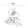
- Figure 1 is a perspective view showing the disassembled rocker arm
- Figure 2 is a cross sectional view showing a using condition of the rocker arm
- Figure 3 is a cross sectional view of a central part in the longitudinal direction of the rocker arm
- Figure 4 is a plan view of the blank work
- Figure 5 is a cross sectional view showing a processing procedure of the body.
- reference numeral 1 denotes a cam
- reference number2 denotes the rocker arm.
- the cam 1 is rotatably furnished around a cam shaft 3 at a predetermined position of the valve mechanism (not shown).
- the rocker arm 2 is used to OHC type engine, and is provided with a body 4 made of sheet metal, roller 5, needle rollers 6 turnably disposed at the side of an inner diameter of the roller 5, and an axis 7 inserted at the side of an inner diameter of the needle rollers 6.
- the body 4 includes a pair of side walls 8, 9 being parallel to each other.
- the axis 7 is bridged between both side walls 8, 9 and non-rotatably attached to the side walls 8, 9 by fitting the axis 7 to circumferential faces of the axial holes 8a, 9a and expanding opposite end faces 7a, 7b outside in the radial direction.
- the outer circumferential portions of the axial holes 8a, 9a are formed to be thickened portions 10, 11 having thickness t2 larger than thickness t1 of blank materials of opposite side walls 8, 9 constituting the body 4.
- t2 1.5 x t1.
- Such thickened portions 10, 11 are formed by causing a metallic material to generate plastic flow when forming the axial holes 8a, 9a.
- a lash adjuster carrier 12 is provided between both opposite side walls 8, 9 at one side in the longitudinal direction of the body 4.
- a lash adjuster 14 slidably fits at its front end to the lash adjuster carrier 12.
- a valve carrier 13 is provided between opposite side walls 8, 9 at the other side in the longitudinal direction of the body 4.
- the valve carrier 13 is incorporated with a front end 15a of a valve stem 15.
- the body 4 is produced by pressing one sheet of metallic sheet, and opposite side walls 8, 9, lash adjuster carrier 12 and valve carrier 13 are formed as one body.
- the body 4 of the above structure is made of the sheet metal.
- the first step is to perform a die-cutting treatment on one sheet of metallic sheet by a pressing process so as to produce a blank material 18 as shown in Figure 4.
- This case employs such a metallic sheet being thinner than metallic sheets used to forming of conventional rocker arms.
- reference numerals 19, 20 denote pre-arranged ranges for forming the side walls 8, 9
- reference numeral 21 denotes the pre-arranged range for forming the lash adjuster carrier 12, and
- reference numeral 22 denotes the pre-arranged range for forming the valve carrier.
- Reference numerals 23, 24 denote the pre-arranged ranges for forming the axial holes 8a, 9a. At a stage of this blank material, sizes of diameters d1 of holes 23a, 24a formed in the pre-arranged ranges for forming the axial holes 8a, 9a are in advance prepared to be enough smaller than the diameter d2 of the axis 7.
- the diameter d1 of the holes 23a, 24a of the pre-arranged ranges 23, 24 is expanded for forming the axial holes 8a, 9a by means of a suited jig 25.
- the expansion process is performed under a condition of holding the blank material 18 at its one side on a metal mold 28.
- the metal mold is formed with a releasing part 27 corresponding to the ranges of the axial holes 8a, 9a, and the jig 28 is positioned to the holes 23a, 24a of the pre-arranged ranges 23, 24 for forming axialholes8a, 9a, and presses the other side of the blank material 18.
- the holes 23a, 24a are expanded, and the metal material by an expanding amount is effected with plastic flow in order to increase thickness as swelling with respect to the pre-arranged ranges 19, 20 so that thickened portions 10, 11 are formed.
- the pre-arranged ranges 19, 20 that form the side walls 8, 9 are bent at the positions shown with imaginary lines 18a, 18b of Figure 4 by a determined metal mold (not shown) so as to form the body having the side walls 8, 9, the lash adjuster carrier 12 and the valve carrier 13 as shown in Figure 1.
- a assembly in which the needle rollers 6 are arrangedon the inner circumference of the roller 5 is disposed between the side walls 8, 9 as shown in Figure 1.
- the axis 7 is inserted from one-side axial hole 9a toward the other axial hole 8a, and is fitted to the circumferential face of the axial holes 8a, 9a of the side walls 8, 9 and is expanded at opposite ends 7a, 7b outside in an axial direction so that the axis 7 is non-rotatably attached to the axial holes 8a, 9a.
- the body 4 oscillates around a fulcrum of a front end 14a of the lash adjuster 14, whereby the valve stem 15 is vertically reciprocated to open and close the valve of the engine.
- the axial holes 8a, 9a secure rigidity at the outer circumference of the axial holes 8a, 9a in such manners that, when forming the axial holes 8a, 9a, the metallic material of the blank material is caused with the plastic flow to make the thickened portions 10, 11 thicker than the thickness of the blank material blank metal material of the side walls 8, 9. Therefore, in this rocker arm 2, even if using the material thinner than the blank material of the body of the conventional rocker arm, the cam 1 is enough durable against such load from the cam 1, and as a result, the rocker arm 2 is enough durable in the severely using circumstance of the valve mechanism of the engine, while realizing reduction in weight by using the thin metallic sheet of the body 4.
- the body 4 is formed with the metallic sheet thinner than the conventional ones, and the axial holes 8a, 9a are formed so that the holes 23a, 24a are expanded for causing the plastic flow in the thickness of the metallic sheet, an amount of scrappingmetal parts is considerably reduced, and accordingly the body 4 of the rocker arm 2 can be heightened in a yield of production.
Landscapes
- Engineering & Computer Science (AREA)
- Mechanical Engineering (AREA)
- General Engineering & Computer Science (AREA)
- Valve-Gear Or Valve Arrangements (AREA)
- Mechanically-Actuated Valves (AREA)
- Forging (AREA)
Applications Claiming Priority (2)
| Application Number | Priority Date | Filing Date | Title |
|---|---|---|---|
| JP2003429613A JP2005188362A (ja) | 2003-12-25 | 2003-12-25 | 板金製ロッカアームおよびその製造方法 |
| JP2003429613 | 2003-12-25 |
Publications (2)
| Publication Number | Publication Date |
|---|---|
| EP1547704A1 EP1547704A1 (en) | 2005-06-29 |
| EP1547704B1 true EP1547704B1 (en) | 2007-07-11 |
Family
ID=34545014
Family Applications (1)
| Application Number | Title | Priority Date | Filing Date |
|---|---|---|---|
| EP04030670A Expired - Lifetime EP1547704B1 (en) | 2003-12-25 | 2004-12-23 | Rocker arm of sheet metal and its method of manufacturing |
Country Status (6)
| Country | Link |
|---|---|
| US (1) | US7222599B2 (https=) |
| EP (1) | EP1547704B1 (https=) |
| JP (1) | JP2005188362A (https=) |
| KR (1) | KR20050065419A (https=) |
| DE (1) | DE602004007466T2 (https=) |
| ES (1) | ES2289420T3 (https=) |
Families Citing this family (5)
| Publication number | Priority date | Publication date | Assignee | Title |
|---|---|---|---|---|
| US7631425B2 (en) * | 2004-12-17 | 2009-12-15 | Nakanishi Metal Works Co., Ltd. | Method for manufacturing rocker arm |
| DE102006048342A1 (de) * | 2006-10-12 | 2008-04-17 | Schaeffler Kg | Schlepphebel |
| DE102011007450A1 (de) * | 2011-04-15 | 2012-10-18 | Schaeffler Technologies AG & Co. KG | Schlepphebel eines Ventiltriebs und Verfahren zu dessen Herstellung |
| DE102011079605A1 (de) * | 2011-07-22 | 2013-01-24 | Schaeffler Technologies AG & Co. KG | Schlepphebel für den Ventiltrieb einer Brennkraftmaschine |
| JP6721374B2 (ja) | 2016-03-29 | 2020-07-15 | 株式会社オティックス | ロッカアーム及びロッカアームの製造方法 |
Family Cites Families (9)
| Publication number | Priority date | Publication date | Assignee | Title |
|---|---|---|---|---|
| JPH0679383A (ja) | 1992-05-29 | 1994-03-22 | Toshiomi Hayashi | ロッカーアームの製造方法 |
| US6516766B2 (en) * | 1997-04-23 | 2003-02-11 | Koyo Seiko Co., Ltd. | Rocker arm |
| US5943897A (en) * | 1997-04-30 | 1999-08-31 | Exedy Corporation | Method for making a hole in a plate and a punch for making such a hole |
| US6199527B1 (en) * | 1998-03-12 | 2001-03-13 | Nsk Ltd. | Sheet metal rocker arm, manufacturing method thereof, cam follower with said rocker arm, and assembling method thereof |
| JP4099909B2 (ja) | 1999-08-18 | 2008-06-11 | 株式会社ジェイテクト | ロッカアーム胴体の製造方法 |
| JP2001271614A (ja) | 2000-03-27 | 2001-10-05 | Toyota Motor Corp | ロッカアーム及びその製造方法 |
| DE50112627D1 (de) * | 2000-06-08 | 2007-07-26 | Adval Tech Holding Ag | Hohlnietverbindung zwischen zwei blechen und verfahren zu ihrer herstellung |
| JP2003056314A (ja) | 2001-08-22 | 2003-02-26 | Nsk Ltd | ロッカーアーム |
| JP2003328704A (ja) | 2001-11-22 | 2003-11-19 | Ntn Corp | ロッカーアーム |
-
2003
- 2003-12-25 JP JP2003429613A patent/JP2005188362A/ja active Pending
-
2004
- 2004-12-22 US US11/018,933 patent/US7222599B2/en not_active Expired - Lifetime
- 2004-12-23 ES ES04030670T patent/ES2289420T3/es not_active Expired - Lifetime
- 2004-12-23 EP EP04030670A patent/EP1547704B1/en not_active Expired - Lifetime
- 2004-12-23 DE DE602004007466T patent/DE602004007466T2/de not_active Expired - Lifetime
- 2004-12-24 KR KR1020040111995A patent/KR20050065419A/ko not_active Ceased
Also Published As
| Publication number | Publication date |
|---|---|
| KR20050065419A (ko) | 2005-06-29 |
| DE602004007466T2 (de) | 2008-03-13 |
| US7222599B2 (en) | 2007-05-29 |
| ES2289420T3 (es) | 2008-02-01 |
| JP2005188362A (ja) | 2005-07-14 |
| EP1547704A1 (en) | 2005-06-29 |
| US20050199204A1 (en) | 2005-09-15 |
| DE602004007466D1 (de) | 2007-08-23 |
Similar Documents
| Publication | Publication Date | Title |
|---|---|---|
| US5678305A (en) | Method for manufacturing a rocker arm with a roller | |
| SK10182003A3 (sk) | Prírubové puzdro, spôsob jeho výroby a ohýbací nástroj na výrobu prírub na puzdre | |
| EP1547704B1 (en) | Rocker arm of sheet metal and its method of manufacturing | |
| JP2008014180A (ja) | カムフォロア装置用支持軸とその製造方法並びに搬送方法 | |
| EP1372881B1 (en) | Method of forming a sheet metal cup without a mandrel | |
| CN101137854A (zh) | 滚针轴承及其制造方法 | |
| US20050034696A1 (en) | Rocker arm | |
| US5904123A (en) | Mechanical valve tappet | |
| JP2805409B2 (ja) | 板金ローラロッカアームとその製造方法 | |
| JP4161658B2 (ja) | カムフォロアの製造方法 | |
| JPH0679383A (ja) | ロッカーアームの製造方法 | |
| JP2001041011A (ja) | ロッカアーム | |
| JPH0771210A (ja) | 軸受ピン | |
| JP4525435B2 (ja) | ロッカアーム | |
| WO2021148243A1 (en) | Switching roller finger follower with inner arm having asymmetric inner roller | |
| JP2017180149A (ja) | ロッカアーム及びロッカアームの製造方法 | |
| JP4009839B2 (ja) | カムフォロア | |
| JP3857639B2 (ja) | ロッカアーム | |
| JP2001003714A (ja) | ロッカアーム | |
| JP2001355413A (ja) | ロッカアーム | |
| JP3438036B2 (ja) | ロッカアーム | |
| US12157161B2 (en) | Method of manufacturing a flange for holding an outer ring of a rolling bearing | |
| US20070039174A1 (en) | Manufacturing a rocker lever using cold forming and welding | |
| JPS6070103A (ja) | 組立カムシヤフトの製造方法 | |
| JP4304043B2 (ja) | カムフォロアの製造方法 |
Legal Events
| Date | Code | Title | Description |
|---|---|---|---|
| PUAI | Public reference made under article 153(3) epc to a published international application that has entered the european phase |
Free format text: ORIGINAL CODE: 0009012 |
|
| AK | Designated contracting states |
Kind code of ref document: A1 Designated state(s): AT BE BG CH CY CZ DE DK EE ES FI FR GB GR HU IE IS IT LI LT LU MC NL PL PT RO SE SI SK TR |
|
| AX | Request for extension of the european patent |
Extension state: AL BA HR LV MK YU |
|
| 17P | Request for examination filed |
Effective date: 20051227 |
|
| AKX | Designation fees paid |
Designated state(s): DE ES FR GB IT NL |
|
| RAP1 | Party data changed (applicant data changed or rights of an application transferred) |
Owner name: JTEKT CORPORATION |
|
| 17Q | First examination report despatched |
Effective date: 20060201 |
|
| GRAP | Despatch of communication of intention to grant a patent |
Free format text: ORIGINAL CODE: EPIDOSNIGR1 |
|
| RIN1 | Information on inventor provided before grant (corrected) |
Inventor name: WASEDA, YOSHITAKAC/O KOYO SEIKO CO., LTD. |
|
| GRAS | Grant fee paid |
Free format text: ORIGINAL CODE: EPIDOSNIGR3 |
|
| GRAA | (expected) grant |
Free format text: ORIGINAL CODE: 0009210 |
|
| AK | Designated contracting states |
Kind code of ref document: B1 Designated state(s): DE ES FR GB IT NL |
|
| REG | Reference to a national code |
Ref country code: GB Ref legal event code: FG4D |
|
| REF | Corresponds to: |
Ref document number: 602004007466 Country of ref document: DE Date of ref document: 20070823 Kind code of ref document: P |
|
| ET | Fr: translation filed | ||
| REG | Reference to a national code |
Ref country code: ES Ref legal event code: FG2A Ref document number: 2289420 Country of ref document: ES Kind code of ref document: T3 |
|
| PGFP | Annual fee paid to national office [announced via postgrant information from national office to epo] |
Ref country code: ES Payment date: 20071228 Year of fee payment: 4 |
|
| PLBE | No opposition filed within time limit |
Free format text: ORIGINAL CODE: 0009261 |
|
| STAA | Information on the status of an ep patent application or granted ep patent |
Free format text: STATUS: NO OPPOSITION FILED WITHIN TIME LIMIT |
|
| 26N | No opposition filed |
Effective date: 20080414 |
|
| GBPC | Gb: european patent ceased through non-payment of renewal fee |
Effective date: 20081223 |
|
| NLV4 | Nl: lapsed or anulled due to non-payment of the annual fee |
Effective date: 20090701 |
|
| PG25 | Lapsed in a contracting state [announced via postgrant information from national office to epo] |
Ref country code: GB Free format text: LAPSE BECAUSE OF NON-PAYMENT OF DUE FEES Effective date: 20081223 Ref country code: NL Free format text: LAPSE BECAUSE OF NON-PAYMENT OF DUE FEES Effective date: 20090701 |
|
| REG | Reference to a national code |
Ref country code: ES Ref legal event code: FD2A Effective date: 20081224 |
|
| PG25 | Lapsed in a contracting state [announced via postgrant information from national office to epo] |
Ref country code: ES Free format text: LAPSE BECAUSE OF NON-PAYMENT OF DUE FEES Effective date: 20081224 |
|
| PGFP | Annual fee paid to national office [announced via postgrant information from national office to epo] |
Ref country code: IT Payment date: 20071231 Year of fee payment: 4 |
|
| REG | Reference to a national code |
Ref country code: FR Ref legal event code: PLFP Year of fee payment: 12 |
|
| PGFP | Annual fee paid to national office [announced via postgrant information from national office to epo] |
Ref country code: FR Payment date: 20151110 Year of fee payment: 12 |
|
| REG | Reference to a national code |
Ref country code: FR Ref legal event code: ST Effective date: 20170831 |
|
| PG25 | Lapsed in a contracting state [announced via postgrant information from national office to epo] |
Ref country code: FR Free format text: LAPSE BECAUSE OF NON-PAYMENT OF DUE FEES Effective date: 20170102 |
|
| PGFP | Annual fee paid to national office [announced via postgrant information from national office to epo] |
Ref country code: DE Payment date: 20201208 Year of fee payment: 17 |
|
| REG | Reference to a national code |
Ref country code: DE Ref legal event code: R119 Ref document number: 602004007466 Country of ref document: DE |
|
| PG25 | Lapsed in a contracting state [announced via postgrant information from national office to epo] |
Ref country code: DE Free format text: LAPSE BECAUSE OF NON-PAYMENT OF DUE FEES Effective date: 20220701 |