EP1547669A1 - Catalyst system and method for the reduction of NOx - Google Patents
Catalyst system and method for the reduction of NOx Download PDFInfo
- Publication number
- EP1547669A1 EP1547669A1 EP04257882A EP04257882A EP1547669A1 EP 1547669 A1 EP1547669 A1 EP 1547669A1 EP 04257882 A EP04257882 A EP 04257882A EP 04257882 A EP04257882 A EP 04257882A EP 1547669 A1 EP1547669 A1 EP 1547669A1
- Authority
- EP
- European Patent Office
- Prior art keywords
- catalyst
- reductant
- mol
- metal oxide
- oxide
- Prior art date
- Legal status (The legal status is an assumption and is not a legal conclusion. Google has not performed a legal analysis and makes no representation as to the accuracy of the status listed.)
- Withdrawn
Links
- 239000003054 catalyst Substances 0.000 title claims abstract description 147
- 238000000034 method Methods 0.000 title claims abstract description 14
- 230000009467 reduction Effects 0.000 title claims description 9
- 239000003638 chemical reducing agent Substances 0.000 claims abstract description 50
- 229910052751 metal Inorganic materials 0.000 claims abstract description 42
- 239000002184 metal Substances 0.000 claims abstract description 42
- 229910044991 metal oxide Inorganic materials 0.000 claims abstract description 39
- 150000004706 metal oxides Chemical class 0.000 claims abstract description 39
- 239000000203 mixture Substances 0.000 claims abstract description 37
- 230000001737 promoting effect Effects 0.000 claims abstract description 30
- 230000003197 catalytic effect Effects 0.000 claims abstract description 23
- 229930195733 hydrocarbon Natural products 0.000 claims abstract description 22
- 150000002430 hydrocarbons Chemical class 0.000 claims abstract description 22
- 229910052709 silver Inorganic materials 0.000 claims abstract description 20
- 239000004332 silver Substances 0.000 claims abstract description 19
- BQCADISMDOOEFD-UHFFFAOYSA-N Silver Chemical compound [Ag] BQCADISMDOOEFD-UHFFFAOYSA-N 0.000 claims abstract description 17
- AJNVQOSZGJRYEI-UHFFFAOYSA-N digallium;oxygen(2-) Chemical compound [O-2].[O-2].[O-2].[Ga+3].[Ga+3] AJNVQOSZGJRYEI-UHFFFAOYSA-N 0.000 claims abstract description 15
- 229910001195 gallium oxide Inorganic materials 0.000 claims abstract description 15
- 125000004432 carbon atom Chemical group C* 0.000 claims abstract description 13
- 239000004215 Carbon black (E152) Substances 0.000 claims abstract description 10
- 239000012530 fluid Substances 0.000 claims abstract description 9
- 229910017052 cobalt Inorganic materials 0.000 claims abstract description 8
- 239000010941 cobalt Substances 0.000 claims abstract description 8
- GUTLYIVDDKVIGB-UHFFFAOYSA-N cobalt atom Chemical compound [Co] GUTLYIVDDKVIGB-UHFFFAOYSA-N 0.000 claims abstract description 8
- 229910052750 molybdenum Inorganic materials 0.000 claims abstract description 8
- 229910052721 tungsten Inorganic materials 0.000 claims abstract description 8
- ZOKXTWBITQBERF-UHFFFAOYSA-N Molybdenum Chemical compound [Mo] ZOKXTWBITQBERF-UHFFFAOYSA-N 0.000 claims abstract description 7
- 229910003437 indium oxide Inorganic materials 0.000 claims abstract description 7
- PJXISJQVUVHSOJ-UHFFFAOYSA-N indium(iii) oxide Chemical compound [O-2].[O-2].[O-2].[In+3].[In+3] PJXISJQVUVHSOJ-UHFFFAOYSA-N 0.000 claims abstract description 7
- 239000011733 molybdenum Substances 0.000 claims abstract description 7
- WFKWXMTUELFFGS-UHFFFAOYSA-N tungsten Chemical compound [W] WFKWXMTUELFFGS-UHFFFAOYSA-N 0.000 claims abstract description 7
- 239000010937 tungsten Substances 0.000 claims abstract description 7
- ATJFFYVFTNAWJD-UHFFFAOYSA-N Tin Chemical compound [Sn] ATJFFYVFTNAWJD-UHFFFAOYSA-N 0.000 claims abstract description 6
- HCHKCACWOHOZIP-UHFFFAOYSA-N Zinc Chemical compound [Zn] HCHKCACWOHOZIP-UHFFFAOYSA-N 0.000 claims abstract description 6
- 229910052797 bismuth Inorganic materials 0.000 claims abstract description 6
- JCXGWMGPZLAOME-UHFFFAOYSA-N bismuth atom Chemical compound [Bi] JCXGWMGPZLAOME-UHFFFAOYSA-N 0.000 claims abstract description 6
- 229910052718 tin Inorganic materials 0.000 claims abstract description 6
- 239000011135 tin Substances 0.000 claims abstract description 6
- 229910052720 vanadium Inorganic materials 0.000 claims abstract description 6
- LEONUFNNVUYDNQ-UHFFFAOYSA-N vanadium atom Chemical compound [V] LEONUFNNVUYDNQ-UHFFFAOYSA-N 0.000 claims abstract description 6
- 229910052725 zinc Inorganic materials 0.000 claims abstract description 6
- 239000011701 zinc Substances 0.000 claims abstract description 6
- 238000002156 mixing Methods 0.000 claims abstract description 5
- 239000007789 gas Substances 0.000 claims description 34
- PNEYBMLMFCGWSK-UHFFFAOYSA-N aluminium oxide Inorganic materials [O-2].[O-2].[O-2].[Al+3].[Al+3] PNEYBMLMFCGWSK-UHFFFAOYSA-N 0.000 claims description 14
- 229910052738 indium Inorganic materials 0.000 claims description 7
- APFVFJFRJDLVQX-UHFFFAOYSA-N indium atom Chemical compound [In] APFVFJFRJDLVQX-UHFFFAOYSA-N 0.000 claims description 5
- GWEVSGVZZGPLCZ-UHFFFAOYSA-N Titan oxide Chemical compound O=[Ti]=O GWEVSGVZZGPLCZ-UHFFFAOYSA-N 0.000 claims description 4
- MCMNRKCIXSYSNV-UHFFFAOYSA-N Zirconium dioxide Chemical compound O=[Zr]=O MCMNRKCIXSYSNV-UHFFFAOYSA-N 0.000 claims description 4
- 238000002485 combustion reaction Methods 0.000 claims description 3
- CETPSERCERDGAM-UHFFFAOYSA-N ceric oxide Chemical compound O=[Ce]=O CETPSERCERDGAM-UHFFFAOYSA-N 0.000 claims description 2
- 229910000422 cerium(IV) oxide Inorganic materials 0.000 claims description 2
- 230000008569 process Effects 0.000 abstract description 5
- MWUXSHHQAYIFBG-UHFFFAOYSA-N Nitric oxide Chemical compound O=[N] MWUXSHHQAYIFBG-UHFFFAOYSA-N 0.000 description 96
- 238000002474 experimental method Methods 0.000 description 16
- TVMXDCGIABBOFY-UHFFFAOYSA-N octane Chemical compound CCCCCCCC TVMXDCGIABBOFY-UHFFFAOYSA-N 0.000 description 14
- QQONPFPTGQHPMA-UHFFFAOYSA-N Propene Chemical compound CC=C QQONPFPTGQHPMA-UHFFFAOYSA-N 0.000 description 12
- 238000006243 chemical reaction Methods 0.000 description 12
- VLKZOEOYAKHREP-UHFFFAOYSA-N n-Hexane Chemical compound CCCCCC VLKZOEOYAKHREP-UHFFFAOYSA-N 0.000 description 12
- 238000006722 reduction reaction Methods 0.000 description 10
- 239000000243 solution Substances 0.000 description 10
- QGZKDVFQNNGYKY-UHFFFAOYSA-N Ammonia Chemical compound N QGZKDVFQNNGYKY-UHFFFAOYSA-N 0.000 description 9
- IJGRMHOSHXDMSA-UHFFFAOYSA-N Atomic nitrogen Chemical compound N#N IJGRMHOSHXDMSA-UHFFFAOYSA-N 0.000 description 9
- ATUOYWHBWRKTHZ-UHFFFAOYSA-N Propane Chemical compound CCC ATUOYWHBWRKTHZ-UHFFFAOYSA-N 0.000 description 8
- XLYOFNOQVPJJNP-UHFFFAOYSA-N water Substances O XLYOFNOQVPJJNP-UHFFFAOYSA-N 0.000 description 8
- OFBQJSOFQDEBGM-UHFFFAOYSA-N n-pentane Natural products CCCCC OFBQJSOFQDEBGM-UHFFFAOYSA-N 0.000 description 7
- 150000002739 metals Chemical class 0.000 description 6
- 238000002360 preparation method Methods 0.000 description 6
- 239000000376 reactant Substances 0.000 description 6
- CHPZKNULDCNCBW-UHFFFAOYSA-N gallium nitrate Chemical compound [Ga+3].[O-][N+]([O-])=O.[O-][N+]([O-])=O.[O-][N+]([O-])=O CHPZKNULDCNCBW-UHFFFAOYSA-N 0.000 description 5
- SGVUHPSBDNVHKL-UHFFFAOYSA-N 1,3-dimethylcyclohexane Chemical compound CC1CCCC(C)C1 SGVUHPSBDNVHKL-UHFFFAOYSA-N 0.000 description 4
- QVGXLLKOCUKJST-UHFFFAOYSA-N atomic oxygen Chemical compound [O] QVGXLLKOCUKJST-UHFFFAOYSA-N 0.000 description 4
- 230000000052 comparative effect Effects 0.000 description 4
- 229910052733 gallium Inorganic materials 0.000 description 4
- 238000011068 loading method Methods 0.000 description 4
- 229910052757 nitrogen Inorganic materials 0.000 description 4
- 239000001301 oxygen Substances 0.000 description 4
- 229910052760 oxygen Inorganic materials 0.000 description 4
- 239000002245 particle Substances 0.000 description 4
- 239000002243 precursor Substances 0.000 description 4
- 239000001294 propane Substances 0.000 description 4
- 229910021529 ammonia Inorganic materials 0.000 description 3
- 238000010531 catalytic reduction reaction Methods 0.000 description 3
- 230000000694 effects Effects 0.000 description 3
- 229910000069 nitrogen hydride Inorganic materials 0.000 description 3
- OKTJSMMVPCPJKN-UHFFFAOYSA-N Carbon Chemical compound [C] OKTJSMMVPCPJKN-UHFFFAOYSA-N 0.000 description 2
- RYGMFSIKBFXOCR-UHFFFAOYSA-N Copper Chemical compound [Cu] RYGMFSIKBFXOCR-UHFFFAOYSA-N 0.000 description 2
- GYHNNYVSQQEPJS-UHFFFAOYSA-N Gallium Chemical compound [Ga] GYHNNYVSQQEPJS-UHFFFAOYSA-N 0.000 description 2
- 230000008901 benefit Effects 0.000 description 2
- 239000006227 byproduct Substances 0.000 description 2
- 229910052799 carbon Inorganic materials 0.000 description 2
- 229910052802 copper Inorganic materials 0.000 description 2
- 239000010949 copper Substances 0.000 description 2
- -1 for example Chemical class 0.000 description 2
- 229940044658 gallium nitrate Drugs 0.000 description 2
- PCHJSUWPFVWCPO-UHFFFAOYSA-N gold Chemical compound [Au] PCHJSUWPFVWCPO-UHFFFAOYSA-N 0.000 description 2
- 229910052737 gold Inorganic materials 0.000 description 2
- 239000010931 gold Substances 0.000 description 2
- 238000010438 heat treatment Methods 0.000 description 2
- 239000007788 liquid Substances 0.000 description 2
- 239000000463 material Substances 0.000 description 2
- 239000011148 porous material Substances 0.000 description 2
- 239000000047 product Substances 0.000 description 2
- 230000001105 regulatory effect Effects 0.000 description 2
- 150000003839 salts Chemical class 0.000 description 2
- 238000012360 testing method Methods 0.000 description 2
- KWKAKUADMBZCLK-UHFFFAOYSA-N 1-octene Chemical compound CCCCCCC=C KWKAKUADMBZCLK-UHFFFAOYSA-N 0.000 description 1
- CBENFWSGALASAD-UHFFFAOYSA-N Ozone Chemical compound [O-][O+]=O CBENFWSGALASAD-UHFFFAOYSA-N 0.000 description 1
- 239000012494 Quartz wool Substances 0.000 description 1
- 238000003916 acid precipitation Methods 0.000 description 1
- 238000003915 air pollution Methods 0.000 description 1
- 150000001335 aliphatic alkanes Chemical class 0.000 description 1
- 150000001336 alkenes Chemical class 0.000 description 1
- 229910045601 alloy Inorganic materials 0.000 description 1
- 239000000956 alloy Substances 0.000 description 1
- 239000007864 aqueous solution Substances 0.000 description 1
- 208000006673 asthma Diseases 0.000 description 1
- 230000015572 biosynthetic process Effects 0.000 description 1
- 239000001273 butane Substances 0.000 description 1
- 150000001722 carbon compounds Chemical class 0.000 description 1
- 238000006555 catalytic reaction Methods 0.000 description 1
- 230000003247 decreasing effect Effects 0.000 description 1
- 230000002939 deleterious effect Effects 0.000 description 1
- 230000006866 deterioration Effects 0.000 description 1
- 229910001873 dinitrogen Inorganic materials 0.000 description 1
- 230000007613 environmental effect Effects 0.000 description 1
- 239000000446 fuel Substances 0.000 description 1
- 231100001261 hazardous Toxicity 0.000 description 1
- 230000008821 health effect Effects 0.000 description 1
- 239000012535 impurity Substances 0.000 description 1
- 229910001055 inconels 600 Inorganic materials 0.000 description 1
- 230000004941 influx Effects 0.000 description 1
- 239000012528 membrane Substances 0.000 description 1
- 229910001960 metal nitrate Inorganic materials 0.000 description 1
- IJDNQMDRQITEOD-UHFFFAOYSA-N n-butane Chemical compound CCCC IJDNQMDRQITEOD-UHFFFAOYSA-N 0.000 description 1
- 150000002823 nitrates Chemical class 0.000 description 1
- 239000011368 organic material Substances 0.000 description 1
- 239000002994 raw material Substances 0.000 description 1
- 230000000241 respiratory effect Effects 0.000 description 1
- 239000012266 salt solution Substances 0.000 description 1
- 238000005070 sampling Methods 0.000 description 1
- 238000012216 screening Methods 0.000 description 1
- 239000004071 soot Substances 0.000 description 1
- 239000007858 starting material Substances 0.000 description 1
- 239000000126 substance Substances 0.000 description 1
- 238000012956 testing procedure Methods 0.000 description 1
- 238000013519 translation Methods 0.000 description 1
- 238000009834 vaporization Methods 0.000 description 1
- 230000008016 vaporization Effects 0.000 description 1
Images
Classifications
-
- B—PERFORMING OPERATIONS; TRANSPORTING
- B01—PHYSICAL OR CHEMICAL PROCESSES OR APPARATUS IN GENERAL
- B01J—CHEMICAL OR PHYSICAL PROCESSES, e.g. CATALYSIS OR COLLOID CHEMISTRY; THEIR RELEVANT APPARATUS
- B01J23/00—Catalysts comprising metals or metal oxides or hydroxides, not provided for in group B01J21/00
- B01J23/38—Catalysts comprising metals or metal oxides or hydroxides, not provided for in group B01J21/00 of noble metals
- B01J23/54—Catalysts comprising metals or metal oxides or hydroxides, not provided for in group B01J21/00 of noble metals combined with metals, oxides or hydroxides provided for in groups B01J23/02 - B01J23/36
- B01J23/66—Silver or gold
-
- B—PERFORMING OPERATIONS; TRANSPORTING
- B01—PHYSICAL OR CHEMICAL PROCESSES OR APPARATUS IN GENERAL
- B01D—SEPARATION
- B01D53/00—Separation of gases or vapours; Recovering vapours of volatile solvents from gases; Chemical or biological purification of waste gases, e.g. engine exhaust gases, smoke, fumes, flue gases, aerosols
- B01D53/34—Chemical or biological purification of waste gases
- B01D53/74—General processes for purification of waste gases; Apparatus or devices specially adapted therefor
- B01D53/86—Catalytic processes
- B01D53/8621—Removing nitrogen compounds
- B01D53/8625—Nitrogen oxides
- B01D53/8628—Processes characterised by a specific catalyst
-
- B—PERFORMING OPERATIONS; TRANSPORTING
- B01—PHYSICAL OR CHEMICAL PROCESSES OR APPARATUS IN GENERAL
- B01J—CHEMICAL OR PHYSICAL PROCESSES, e.g. CATALYSIS OR COLLOID CHEMISTRY; THEIR RELEVANT APPARATUS
- B01J23/00—Catalysts comprising metals or metal oxides or hydroxides, not provided for in group B01J21/00
- B01J23/08—Catalysts comprising metals or metal oxides or hydroxides, not provided for in group B01J21/00 of gallium, indium or thallium
-
- B—PERFORMING OPERATIONS; TRANSPORTING
- B01—PHYSICAL OR CHEMICAL PROCESSES OR APPARATUS IN GENERAL
- B01J—CHEMICAL OR PHYSICAL PROCESSES, e.g. CATALYSIS OR COLLOID CHEMISTRY; THEIR RELEVANT APPARATUS
- B01J23/00—Catalysts comprising metals or metal oxides or hydroxides, not provided for in group B01J21/00
- B01J23/16—Catalysts comprising metals or metal oxides or hydroxides, not provided for in group B01J21/00 of arsenic, antimony, bismuth, vanadium, niobium, tantalum, polonium, chromium, molybdenum, tungsten, manganese, technetium or rhenium
- B01J23/24—Chromium, molybdenum or tungsten
-
- B—PERFORMING OPERATIONS; TRANSPORTING
- B01—PHYSICAL OR CHEMICAL PROCESSES OR APPARATUS IN GENERAL
- B01J—CHEMICAL OR PHYSICAL PROCESSES, e.g. CATALYSIS OR COLLOID CHEMISTRY; THEIR RELEVANT APPARATUS
- B01J23/00—Catalysts comprising metals or metal oxides or hydroxides, not provided for in group B01J21/00
- B01J23/70—Catalysts comprising metals or metal oxides or hydroxides, not provided for in group B01J21/00 of the iron group metals or copper
- B01J23/76—Catalysts comprising metals or metal oxides or hydroxides, not provided for in group B01J21/00 of the iron group metals or copper combined with metals, oxides or hydroxides provided for in groups B01J23/02 - B01J23/36
- B01J23/825—Catalysts comprising metals or metal oxides or hydroxides, not provided for in group B01J21/00 of the iron group metals or copper combined with metals, oxides or hydroxides provided for in groups B01J23/02 - B01J23/36 with gallium, indium or thallium
-
- B—PERFORMING OPERATIONS; TRANSPORTING
- B01—PHYSICAL OR CHEMICAL PROCESSES OR APPARATUS IN GENERAL
- B01J—CHEMICAL OR PHYSICAL PROCESSES, e.g. CATALYSIS OR COLLOID CHEMISTRY; THEIR RELEVANT APPARATUS
- B01J23/00—Catalysts comprising metals or metal oxides or hydroxides, not provided for in group B01J21/00
- B01J23/70—Catalysts comprising metals or metal oxides or hydroxides, not provided for in group B01J21/00 of the iron group metals or copper
- B01J23/76—Catalysts comprising metals or metal oxides or hydroxides, not provided for in group B01J21/00 of the iron group metals or copper combined with metals, oxides or hydroxides provided for in groups B01J23/02 - B01J23/36
- B01J23/835—Catalysts comprising metals or metal oxides or hydroxides, not provided for in group B01J21/00 of the iron group metals or copper combined with metals, oxides or hydroxides provided for in groups B01J23/02 - B01J23/36 with germanium, tin or lead
-
- B—PERFORMING OPERATIONS; TRANSPORTING
- B01—PHYSICAL OR CHEMICAL PROCESSES OR APPARATUS IN GENERAL
- B01D—SEPARATION
- B01D2255/00—Catalysts
- B01D2255/20—Metals or compounds thereof
Definitions
- This invention relates generally to a catalyst system and method for the reduction of nitrogen oxide emissions and more particularly to a catalyst system that includes a multi-component catalyst and reductant.
- NO x nitrogen oxides
- SCR selective catalytic reduction
- NH 3 ammonia
- a catalyst system comprising a catalyst and a reductant
- the catalyst comprises a metal oxide catalyst support, a catalytic metal oxide comprising at least one of gallium oxide and indium oxide, and a promoting metal comprising at least one of silver, cobalt, vanadium, molybdenum, tungsten, zinc, tin and bismuth.
- the catalyst comprises about 5 to about 31 mol% catalytic metal oxide and about 0.5 to about 9 mol% promoting metal.
- the reductant comprises a fluid hydrocarbon having at least 4 carbon atoms.
- the method comprises mixing a NO x containing effluent gas with a fluid hydrocarbon reductant comprising at least 4 carbon atoms to create a gas mixture and passing the gas mixture through a catalyst.
- the catalyst through which the gas mixture is passed comprises a metal oxide catalyst support, a catalytic metal oxide comprising at least one of gallium oxide and indium oxide, and a promoting metal comprising at least one of silver, cobalt, vanadium, molybdenum, tungsten, zinc, tin and bismuth, wherein the catalyst comprises about 5 to about 31 mol% catalytic metal oxide and about 0.5 to about 9 mol% promoting metal.
- a catalyst system for the selective reduction of NO x comprises a catalyst and a reductant according to exemplary embodiments of the invention.
- the catalyst comprises a metal oxide catalyst support, a catalytic metal oxide, and a promoting metal.
- the reductant comprises a fluid hydrocarbon having at least 4 carbon atoms.
- the metal oxide catalyst support may comprise alumina, titania, zirconia, ceria or any mixture of these materials. Typically, the metal oxide catalyst support comprises alumina.
- the metal oxide catalyst support may be made by any method known to those of skill in the art, such as the sol-gel technique for example.
- the catalyst also comprises a catalytic metal oxide.
- the catalytic metal oxide comprises gallium oxide, indium oxide, or a mixture of the two.
- the catalyst comprises about 5 to about 31 mol% catalytic metal oxide.
- the gallium oxide may typically be present in higher amounts than the indium.
- the catalyst may comprise 20-30 mol% gallium, while the catalyst may comprise about 1 to about 4 mol% indium.
- the catalyst also comprises a promoting metal.
- the promoting metal may comprise any one of cobalt, silver, vanadium, molybdenum, tungsten, zinc, tin, or bismuth. Additionally, the promoting metal may also be a combination of more than one of these metals.
- the catalyst typically comprises about 0.5 to about 9 mol% of the promoting metal, more typically less than about 6 mol%. When the promoting metal comprises silver, the catalyst preferably comprises about 2 mol% silver. It should be appreciated that the term "promoting metal" is meant to encompass elemental metals, metal oxides or salts of the promoting metal, such as CoO for example.
- the catalysts may be produced by an incipient wetness technique, involving the application of aqueous precursor solutions of catalytic material added to the metal oxide catalyst support.
- the metal oxide particles for the catalyst support may first be calcined at about 725 °C. The particles are sifted to collect and use those which are from about 450 to about 1000 micrometers in diameter. Based on the surface area of the metal oxide particles, the desired loading of the catalyst may then be calculated. As will be appreciated by those of ordinary skill in the art, the surface area and porosity may be up to about 20-30% lower in the final catalyst product, as a result of catalyst loading.
- aqueous precursor solutions of the catalytic metal oxide and promoting metal(s) may be prepared.
- the solutions are typically made by mixing water with metal salts, such as metal nitrates for example, in an amount to create a solution of appropriate molarity, based on the desired catalyst composition.
- the desired volume of the precursor solutions is added to coat the metal oxide catalyst support and create a catalyst with the desired final catalyst loading.
- the catalyst may be left to stand for about 6 to 10 hours.
- the catalyst is then dried for about 4 to 5 hours at about 80°C under a vacuum while a nitrogen stream is passed over the mixture. Finally, the catalyst is calcined at about 650°C for about 6 hours to create the final catalyst product.
- Catalysts according to exemplary embodiments of the present invention may be created using either a manual or automated process.
- manual preparation is used for the preparation of catalysts of a larger mass, such as about 1 to about 20 g for example.
- Automatic preparation is typically used when the catalysts are of a smaller mass, such as about 50 to about 100 mg, for example.
- manual and automatic preparation of the catalyst is identical with the exception that automatic preparation involves automated measuring and dispensing of the aqueous precursor solutions to the metal oxide catalyst support.
- the reductant for use in the catalyst system of exemplary embodiments of the present invention comprises hydrocarbons having at least 4 carbon atoms.
- the hydrocarbons are fluid, either as a liquid or gas, such that they may flow through the catalyst when introduced into an effluent gas stream for use in a catalyst system for the reduction of NO x .
- hydrocarbons of less than about 16 carbon atoms will be fluid, although hydrocarbons with higher numbers of carbon atoms may also be fluid, for example, depending on the chemical structure and temperature of the gas stream.
- the hydrocarbons may be any type of hydrocarbon, including, for example, alkanes and alkenes whether straight chain, branched or cyclical.
- the reductant may comprise hydrocarbons that are all of the same type or it may contain a mixture of different hydrocarbons. Further, the mixture may be a mixture of hydrocarbons all having the same number of carbon atoms such as octane, octene and 1,3-dimethyl-cyclohexane, for example. Likewise, the mixture may be a mixture of hydrocarbons having different numbers of carbon atoms such as hexane and butane, for example.
- One particularly suitable mixture of hydrocarbons for use as a reductant in the catalyst system of various embodiments of the invention is gasoline. As will be appreciated by those of skill in the art, gasoline is typically a mixture of linear and branched hydrocarbons, with a majority of the hydrocarbons having between about 5 and about 12 carbon atoms.
- the catalyst system may be used in conjunction with any system in which it may be desirable to reduce NO x emissions, such as gas turbine and transportation exhaust systems, for example.
- the catalyst is typically placed at a location within an exhaust system where it will be exposed to effluent gas containing NO x .
- the catalyst may be arranged as a packed or fluidized bed reactor, coated on a monolithic or membrane structure, or arranged in any other manner within the exhaust system such that the catalyst is in contact with the effluent gas.
- the effluent gas stream usually contains air, water, CO, CO 2 , NO x , and may also contain other impurities, such as SO 2 for example. Additionally, uncombusted or incompletely combusted fuel may also be present in the effluent gas stream.
- the hydrocarbon reductant is fed into the effluent gas stream and through the catalyst. Sufficient oxygen to support the NO x reduction reaction may already be present in the effluent gas stream, but if not, additional oxygen may also be introduced into the effluent gas stream. Oxygen may typically be present in the effluent gas stream containing the reductant at greater than about 5 % by volume, more typically about 10 to about 20 % by volume.
- One advantage of embodiments of the present invention is that the reduction reaction may take place in "lean" conditions. That is, the amount of reductant added to the effluent gas to reduce the NO x is generally low.
- the molar ratio of reductant to NO x is typically from about 0.25:1 to about 3:1. More specifically, the ratio is typically such that the ratio of carbon atoms in the reductant is about 1 to about 24 moles per one mole of NO x . Reducing the amount of reductant to convert the NO x to nitrogen may provide for a more efficient process that has decreased raw material costs.
- the reduction reaction may take place over a range of temperatures. Typically, the temperature may range from about 300 to about 600°C, more typically about 350 to about 450°C.
- Exemplary embodiments of the catalyst system of the invention may also advantageously be used in wet conditions. NO x reduction accomplished using exemplary embodiments of the present invention may be effective in effluent gas streams having up to about 1.0 % water or more by volume. Increasing the percentage of water up to about 7 to about 9% by volume may also result in an increase in catalyst activity. After about 7-9% water by volume, catalyst activity may stabilize and no longer increase with increasing water amounts, although the catalyst system may continue to be effective.
- Catalysts in accordance with exemplary embodiments of the invention were prepared and used in combination with reductants also in accordance with exemplary embodiments of the invention.
- the conversion of the NO x was analyzed over a variety of experimental conditions, including varying catalyst compositions, reductants, reaction temperatures, compositions of reactant streams and reductant to NO x ratios.
- the following examples are for the purpose of illustrating exemplary embodiments of the invention and are not intended to be limiting.
- Catalyst samples were prepared having an alumina catalyst support.
- the type and amounts of metal oxide and promoting metal in the samples were varied to produce different catalysts in accordance with exemplary embodiments of the invention.
- Table 1 shows the compositions of the catalyst samples prepared, with compositions expressed in mole percent of each promoting metal and/or catalytic metal present in the catalyst.
- the balance of the composition is alumina from the alumina catalyst support. Mole percent was determined for each component by dividing the number of moles of that component by the total number of moles of the metal components in the catalyst, including the metal components of the catalyst support.
- Catalyst compositions numbered 1-4, 9 and 12 were prepared for comparative purposes.
- Each catalyst sample was prepared with alumina as the metal oxide catalyst support.
- Starting materials for the catalyst included alumina catalyst support commercially available from Saint-Gobain NorPro of Stow, OH.
- the alumina catalyst support had a purity of greater than 99% and was then calcined and sieved as previously described to create the catalyst support having a particle size diameter of about 450 to about 1000 micrometers.
- Prior to loading, the catalyst support had a surface area of about 240 m 2 /g and a pore volume of 0.796 mUg.
- Gallium was used as the metal for the catalytic metal oxide added to the alumina, which was weighed to determine the total pore volume.
- the gallium oxide was added to wet the alumina support and was made from a solution of gallium nitrate having the formula Ga(NO 3 ) 3 ⁇ 6 H 2 O.
- the solution was made by combining water with gallium nitrate having a purity of 99.999% (metals basis) obtained from Alfa-Aesar of Ward Hill, MA.
- the promoting metal such as silver
- an aqueous solution of the nitrate salt of the desired metal(s) also having a purity of 99.999% (metals basis) and obtained from Alfa-Aesar was added to the alumina support.
- the catalysts were left to stand for 6 to 10 hours and were then dried under a dynamic vacuum with a nitrogen influx for 4 to 5 hours at 80°C. Finally, the dried catalyst was heat treated.
- the heat profile for this treatment began with an increase from 25°C at 1.4°C/min to 110°C.
- the catalyst was held at 110°C for 1.5 hours, after which the temperature was ramped at 5°C/min until 650°C.
- the catalyst was then held 6 hours at this temperature and then allowed to cool over a period of about 4 to 6 hours.
- Catalysts were tested in a 32-tube high-throughput heterogeneous catalyst-screening micro-reactor.
- the reactor was a heated, common headspace gas distribution manifold that distributed a reactant stream equally via matched capillaries to parallel reactor tubes.
- the manifold had heated capabilities, allowing pre-heating of the reactant stream and vaporization of liquid reactants prior to distribution.
- the entire heated manifold assembly was mounted on a vertical translation stage, raised and lowered via pneumatic pressure.
- Reactor tubes were inserted in a gold-coated 10 cm thick insulated copper reactor block, which was electrically heated to vary temperature between 200°C to 800°C.
- KALREZ o-rings available from DuPont of Wilmington, DE served as viscoelastic end-seals on either end of each reactor tube.
- Reaction tubes were made of INCONEL 600 tubing with 0.635 cm outside diameter, 0.457 cm internal diameter, available from Inco Alloys/Special Metals of Saddle Brook, NJ. The tubes were free to slide vertically through the gold-coated copper heating block.
- Each tube contained a quartz wool frit, on which the catalyst samples of about 0.050 g were placed in the center of each of the tubes through which a reactant stream of a blended gas mixture including NO x and reductant simulating an effluent gas stream was passed.
- a single bypass tube was used to ensure equal flow through each of the 32 testing tubes.
- the fittings were connected to a distribution manifold for delivery of the blended gas mixture.
- the components of the blended gas mixture were fed to a common mixing manifold, using electronic mass flow controllers, and then routed to a distribution manifold.
- the pressure in the distribution manifold was maintained at about 275.8 kPa (about 40 psi). Reactor temperature and flow control were fully automated.
- the catalysts were heat-treated under airflow and then reacted with the blended gas mixture.
- the reactor effluent was sent to heated sampling valves that selected tubes in series and fed the continuous stream to an analytical device. Any stream that was not routed to the analytical device was routed to a common vent.
- the switching valves were computer controlled and actuated in a predetermined time-based sequence.
- the gas analyzer was connected to a computer-based data-logging system. Data corresponding to sample-tube effluent composition was time-stamped and stored. Data from the bypass tube was also stored as a reference to the inlet composition of the catalyst sample tubes. This permitted the combination of data to determine activity and selectivity of each catalyst sample.
- the reactant stream of the blended gas mixture contained reductant, about 200 ppm NO x , 12% by volume oxygen, 7% by volume water and the balance nitrogen.
- the type and amount of reductant in the stream varied depending on the experiments being conducted.
- the flow rate of the blended gas mixture through each of the tubes was 33 standard cubic centimeters per minute (sccm) per tube.
- catalysts 5 and 7 having a combination of gallium oxide as a catalytic metal oxide and silver as a promoting metal showed particularly good results using reductants other than propane and propene.
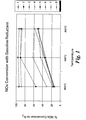
- a third experiment used gasoline as a reductant comparing conversion of NO x as a function of reaction temperature.
- the gasoline used for the experiment had an octane number of 87.
- the reaction conditions were as described above using 600 ppm of reductant.
- Results for the third experiment are summarized in Table 4 and are shown graphically in Figure 1.
- catalyst numbers correspond to the catalyst compositions identified in Table 1.
- Catalyst Reaction Temperature 350 C 400 C 450 C 1 13 34 50 2 55 90 89 3 17 44 48 4 31 62 60 5 93 96 93 6 15 32 49 7 88 90 86 8 14 35 57
- catalysts 5 and 7 both of which contained 2 mol% silver were particularly effective, although all compositions resulted in some conversion of NO x .
- a fourth experiment further explored catalysts having various amounts of silver as a promoting metal in combination with an alumina catalyst support and a catalytic metal oxide.
- Conditions for Experiment 4 were the same as those described.
- Reductants used for this experiment were octane and gasoline (octane number 87). The octane was fed at an octane to NO x molar ratio of 1:1 while gasoline was fed at a gasoline to NO x molar ratio of 3:1.
- Results for the fourth experiment, which was run at 400 °C and 450 °C, are shown below in Table 5.
- Additional catalysts with an alumina catalyst support and catalytic gallium oxide were prepared with tungsten and molybdenum as promoting metals, as shown in the table of compositions shown in Table 6. Some of these preparations also included indium as a promoting metal.
- a comparative sample, catalyst 20, of just gallium oxide and indium was also prepared. Catalyst: 20 21 22 23 24 %W 0 2 0 9 3 %Mo 0 4 4 0 0 %In 2 0 4 0 3 % Ga 25 25 20 20 22
Landscapes
- Chemical & Material Sciences (AREA)
- Engineering & Computer Science (AREA)
- Chemical Kinetics & Catalysis (AREA)
- Materials Engineering (AREA)
- Organic Chemistry (AREA)
- Environmental & Geological Engineering (AREA)
- Health & Medical Sciences (AREA)
- Biomedical Technology (AREA)
- Analytical Chemistry (AREA)
- General Chemical & Material Sciences (AREA)
- Oil, Petroleum & Natural Gas (AREA)
- Catalysts (AREA)
- Exhaust Gas Treatment By Means Of Catalyst (AREA)
Abstract
Description
- This invention relates generally to a catalyst system and method for the reduction of nitrogen oxide emissions and more particularly to a catalyst system that includes a multi-component catalyst and reductant.
- Solutions have long been sought to reduce the deleterious effects of air pollution caused by byproducts resulting from the high-temperature imperfect combustion of organic materials. When combustion occurs in the presence of excess air and at high temperatures, harmful byproducts, such as nitrogen oxides (NOx), are created. NOx plays a major role in the formation of ground-level ozone that is associated with asthma and other respiratory ailments. NOx also contributes to soot, linked to a number of serious health effects, as well as acid rain and the deterioration of coastal estuaries. As a result, NOx emissions are subject to many regulatory provisions limiting the amount of NOx that may be present in effluent gas vented into the surrounding environment.
- One known solution involves the use of selective catalytic reduction (SCR) to reduce NOx to nitrogen gas (N2) using ammonia (NH3) as a reductant. However, as ammonia's own hazardous consequences become better known, the use of NH3 in a SCR system presents additional environmental and other problems that must also be addressed.
- As regulatory agencies continue to drive limits on NOx emission lower, other regulations are also driving down the permissible levels of NH3 that may be emitted into the atmosphere.
- Accordingly, it may be desirable to provide a catalyst system for the selective catalytic reduction of NOx that reduces or even avoids the use ammonia as a reductant but that still results in good conversion of NOx to N2.
- In one exemplary embodiment of the invention, a catalyst system comprising a catalyst and a reductant is disclosed. The catalyst comprises a metal oxide catalyst support, a catalytic metal oxide comprising at least one of gallium oxide and indium oxide, and a promoting metal comprising at least one of silver, cobalt, vanadium, molybdenum, tungsten, zinc, tin and bismuth. The catalyst comprises about 5 to about 31 mol% catalytic metal oxide and about 0.5 to about 9 mol% promoting metal. The reductant comprises a fluid hydrocarbon having at least 4 carbon atoms.
- Also disclosed is a process for reducing NOx from an effluent gas. The method comprises mixing a NOx containing effluent gas with a fluid hydrocarbon reductant comprising at least 4 carbon atoms to create a gas mixture and passing the gas mixture through a catalyst. The catalyst through which the gas mixture is passed comprises a metal oxide catalyst support, a catalytic metal oxide comprising at least one of gallium oxide and indium oxide, and a promoting metal comprising at least one of silver, cobalt, vanadium, molybdenum, tungsten, zinc, tin and bismuth, wherein the catalyst comprises about 5 to about 31 mol% catalytic metal oxide and about 0.5 to about 9 mol% promoting metal.
- Additional aspects, features and advantages of the present invention will be more apparent when considered in light of the following detailed description of exemplary embodiments of the invention.
- The invention will now be described in greater detail, by way of example, with reference to the drawings, the single figure of which is a graphical representation of NOx reduction as a function of temperature of various exemplary embodiments of the invention.
- A catalyst system for the selective reduction of NOx comprises a catalyst and a reductant according to exemplary embodiments of the invention. The catalyst comprises a metal oxide catalyst support, a catalytic metal oxide, and a promoting metal. The reductant comprises a fluid hydrocarbon having at least 4 carbon atoms.
- The metal oxide catalyst support may comprise alumina, titania, zirconia, ceria or any mixture of these materials. Typically, the metal oxide catalyst support comprises alumina. The metal oxide catalyst support may be made by any method known to those of skill in the art, such as the sol-gel technique for example.
- The catalyst also comprises a catalytic metal oxide. The catalytic metal oxide comprises gallium oxide, indium oxide, or a mixture of the two. The catalyst comprises about 5 to about 31 mol% catalytic metal oxide. When the catalytic metal oxide is a mixture of gallium oxide and indium oxide, the gallium oxide may typically be present in higher amounts than the indium. In certain embodiments of the invention, the catalyst may comprise 20-30 mol% gallium, while the catalyst may comprise about 1 to about 4 mol% indium.
- The catalyst also comprises a promoting metal. The promoting metal may comprise any one of cobalt, silver, vanadium, molybdenum, tungsten, zinc, tin, or bismuth. Additionally, the promoting metal may also be a combination of more than one of these metals. The catalyst typically comprises about 0.5 to about 9 mol% of the promoting metal, more typically less than about 6 mol%. When the promoting metal comprises silver, the catalyst preferably comprises about 2 mol% silver. It should be appreciated that the term "promoting metal" is meant to encompass elemental metals, metal oxides or salts of the promoting metal, such as CoO for example.
- The catalysts may be produced by an incipient wetness technique, involving the application of aqueous precursor solutions of catalytic material added to the metal oxide catalyst support. The metal oxide particles for the catalyst support may first be calcined at about 725 °C. The particles are sifted to collect and use those which are from about 450 to about 1000 micrometers in diameter. Based on the surface area of the metal oxide particles, the desired loading of the catalyst may then be calculated. As will be appreciated by those of ordinary skill in the art, the surface area and porosity may be up to about 20-30% lower in the final catalyst product, as a result of catalyst loading.
- Next, aqueous precursor solutions of the catalytic metal oxide and promoting metal(s) may be prepared. The solutions are typically made by mixing water with metal salts, such as metal nitrates for example, in an amount to create a solution of appropriate molarity, based on the desired catalyst composition. The desired volume of the precursor solutions is added to coat the metal oxide catalyst support and create a catalyst with the desired final catalyst loading. Once the metal salt solution(s) have been added to the metal oxide catalyst support, the catalyst may be left to stand for about 6 to 10 hours. The catalyst is then dried for about 4 to 5 hours at about 80°C under a vacuum while a nitrogen stream is passed over the mixture. Finally, the catalyst is calcined at about 650°C for about 6 hours to create the final catalyst product.
- Catalysts according to exemplary embodiments of the present invention may be created using either a manual or automated process. Typically, manual preparation is used for the preparation of catalysts of a larger mass, such as about 1 to about 20 g for example. Automatic preparation is typically used when the catalysts are of a smaller mass, such as about 50 to about 100 mg, for example. Generally, manual and automatic preparation of the catalyst is identical with the exception that automatic preparation involves automated measuring and dispensing of the aqueous precursor solutions to the metal oxide catalyst support.
- The reductant for use in the catalyst system of exemplary embodiments of the present invention comprises hydrocarbons having at least 4 carbon atoms. The hydrocarbons are fluid, either as a liquid or gas, such that they may flow through the catalyst when introduced into an effluent gas stream for use in a catalyst system for the reduction of NOx. Typically, hydrocarbons of less than about 16 carbon atoms will be fluid, although hydrocarbons with higher numbers of carbon atoms may also be fluid, for example, depending on the chemical structure and temperature of the gas stream. The hydrocarbons may be any type of hydrocarbon, including, for example, alkanes and alkenes whether straight chain, branched or cyclical.
- The reductant may comprise hydrocarbons that are all of the same type or it may contain a mixture of different hydrocarbons. Further, the mixture may be a mixture of hydrocarbons all having the same number of carbon atoms such as octane, octene and 1,3-dimethyl-cyclohexane, for example. Likewise, the mixture may be a mixture of hydrocarbons having different numbers of carbon atoms such as hexane and butane, for example. One particularly suitable mixture of hydrocarbons for use as a reductant in the catalyst system of various embodiments of the invention is gasoline. As will be appreciated by those of skill in the art, gasoline is typically a mixture of linear and branched hydrocarbons, with a majority of the hydrocarbons having between about 5 and about 12 carbon atoms.
- The catalyst system may be used in conjunction with any system in which it may be desirable to reduce NOx emissions, such as gas turbine and transportation exhaust systems, for example. The catalyst is typically placed at a location within an exhaust system where it will be exposed to effluent gas containing NOx. The catalyst may be arranged as a packed or fluidized bed reactor, coated on a monolithic or membrane structure, or arranged in any other manner within the exhaust system such that the catalyst is in contact with the effluent gas.
- As will be appreciated by those ordinarily skilled in the art, although catalytic reactions are generally complex and involve many steps, the overall basic selective catalytic reduction reaction process for the reduction of NOx occurs as follows:
- The effluent gas stream usually contains air, water, CO, CO2, NOx, and may also contain other impurities, such as SO2 for example. Additionally, uncombusted or incompletely combusted fuel may also be present in the effluent gas stream. The hydrocarbon reductant is fed into the effluent gas stream and through the catalyst. Sufficient oxygen to support the NOx reduction reaction may already be present in the effluent gas stream, but if not, additional oxygen may also be introduced into the effluent gas stream. Oxygen may typically be present in the effluent gas stream containing the reductant at greater than about 5 % by volume, more typically about 10 to about 20 % by volume.
- One advantage of embodiments of the present invention is that the reduction reaction may take place in "lean" conditions. That is, the amount of reductant added to the effluent gas to reduce the NOx is generally low. The molar ratio of reductant to NOx is typically from about 0.25:1 to about 3:1. More specifically, the ratio is typically such that the ratio of carbon atoms in the reductant is about 1 to about 24 moles per one mole of NOx. Reducing the amount of reductant to convert the NOx to nitrogen may provide for a more efficient process that has decreased raw material costs.
- The reduction reaction may take place over a range of temperatures. Typically, the temperature may range from about 300 to about 600°C, more typically about 350 to about 450°C.
- Exemplary embodiments of the catalyst system of the invention may also advantageously be used in wet conditions. NOx reduction accomplished using exemplary embodiments of the present invention may be effective in effluent gas streams having up to about 1.0 % water or more by volume. Increasing the percentage of water up to about 7 to about 9% by volume may also result in an increase in catalyst activity. After about 7-9% water by volume, catalyst activity may stabilize and no longer increase with increasing water amounts, although the catalyst system may continue to be effective.
- Catalysts in accordance with exemplary embodiments of the invention were prepared and used in combination with reductants also in accordance with exemplary embodiments of the invention. The conversion of the NOx was analyzed over a variety of experimental conditions, including varying catalyst compositions, reductants, reaction temperatures, compositions of reactant streams and reductant to NOx ratios. The following examples are for the purpose of illustrating exemplary embodiments of the invention and are not intended to be limiting.
- Catalyst samples were prepared having an alumina catalyst support. The type and amounts of metal oxide and promoting metal in the samples were varied to produce different catalysts in accordance with exemplary embodiments of the invention.
- Table 1 shows the compositions of the catalyst samples prepared, with compositions expressed in mole percent of each promoting metal and/or catalytic metal present in the catalyst. The balance of the composition is alumina from the alumina catalyst support. Mole percent was determined for each component by dividing the number of moles of that component by the total number of moles of the metal components in the catalyst, including the metal components of the catalyst support. Catalyst compositions numbered 1-4, 9 and 12 were prepared for comparative purposes.
Catalyst 1 2 3 4 5 6 7 8 9 10 11 12 13 14 15 16 17 18 19 %Ag 0 2 0 0 2 0 2 0 5 0 0 9 4 9 1 2 3 4 6 %Co 0 0 0 0 0 2 0 3 0 4 4 0 0 0 0 0 0 0 0 %In 0 0 4 2 0 0 2 3 0 0 4 0 0 0 6 2 3 4 1 % Ga 29 0 0 27 27 27 25 22 0 27 20 0 25 20 22 25 22 21 22 - Each catalyst sample was prepared with alumina as the metal oxide catalyst support. Starting materials for the catalyst included alumina catalyst support commercially available from Saint-Gobain NorPro of Stow, OH. The alumina catalyst support had a purity of greater than 99% and was then calcined and sieved as previously described to create the catalyst support having a particle size diameter of about 450 to about 1000 micrometers. Prior to loading, the catalyst support had a surface area of about 240 m2/g and a pore volume of 0.796 mUg.
- Gallium was used as the metal for the catalytic metal oxide added to the alumina, which was weighed to determine the total pore volume. The gallium oxide was added to wet the alumina support and was made from a solution of gallium nitrate having the formula Ga(NO3)3 · 6 H2O. The solution was made by combining water with gallium nitrate having a purity of 99.999% (metals basis) obtained from Alfa-Aesar of Ward Hill, MA. For the promoting metal, such as silver, for example, an aqueous solution of the nitrate salt of the desired metal(s) also having a purity of 99.999% (metals basis) and obtained from Alfa-Aesar was added to the alumina support. The catalysts were left to stand for 6 to 10 hours and were then dried under a dynamic vacuum with a nitrogen influx for 4 to 5 hours at 80°C. Finally, the dried catalyst was heat treated. The heat profile for this treatment began with an increase from 25°C at 1.4°C/min to 110°C. The catalyst was held at 110°C for 1.5 hours, after which the temperature was ramped at 5°C/min until 650°C. The catalyst was then held 6 hours at this temperature and then allowed to cool over a period of about 4 to 6 hours.
- Catalysts were tested in a 32-tube high-throughput heterogeneous catalyst-screening micro-reactor. The reactor was a heated, common headspace gas distribution manifold that distributed a reactant stream equally via matched capillaries to parallel reactor tubes. The manifold had heated capabilities, allowing pre-heating of the reactant stream and vaporization of liquid reactants prior to distribution. The entire heated manifold assembly was mounted on a vertical translation stage, raised and lowered via pneumatic pressure. Reactor tubes were inserted in a gold-coated 10 cm thick insulated copper reactor block, which was electrically heated to vary temperature between 200°C to 800°C.
- Chemically inert KALREZ o-rings available from DuPont of Wilmington, DE served as viscoelastic end-seals on either end of each reactor tube. Reaction tubes were made of INCONEL 600 tubing with 0.635 cm outside diameter, 0.457 cm internal diameter, available from Inco Alloys/Special Metals of Saddle Brook, NJ. The tubes were free to slide vertically through the gold-coated copper heating block. Each tube contained a quartz wool frit, on which the catalyst samples of about 0.050 g were placed in the center of each of the tubes through which a reactant stream of a blended gas mixture including NOx and reductant simulating an effluent gas stream was passed. A single bypass tube was used to ensure equal flow through each of the 32 testing tubes. The fittings were connected to a distribution manifold for delivery of the blended gas mixture. The components of the blended gas mixture were fed to a common mixing manifold, using electronic mass flow controllers, and then routed to a distribution manifold. The pressure in the distribution manifold was maintained at about 275.8 kPa (about 40 psi). Reactor temperature and flow control were fully automated.
- Once loaded in the tubes, the catalysts were heat-treated under airflow and then reacted with the blended gas mixture. The reactor effluent was sent to heated sampling valves that selected tubes in series and fed the continuous stream to an analytical device. Any stream that was not routed to the analytical device was routed to a common vent.
- The switching valves were computer controlled and actuated in a predetermined time-based sequence. The gas analyzer was connected to a computer-based data-logging system. Data corresponding to sample-tube effluent composition was time-stamped and stored. Data from the bypass tube was also stored as a reference to the inlet composition of the catalyst sample tubes. This permitted the combination of data to determine activity and selectivity of each catalyst sample.
- For NOx reduction testing, the reactant stream of the blended gas mixture contained reductant, about 200 ppm NOx, 12% by volume oxygen, 7% by volume water and the balance nitrogen. The type and amount of reductant in the stream varied depending on the experiments being conducted. The flow rate of the blended gas mixture through each of the tubes was 33 standard cubic centimeters per minute (sccm) per tube.
- A first experiment was conducted in which various catalyst samples were prepared and tested using the described testing procedure. In this experiment, reductants including propane, propene, pentane, hexane and octane were analyzed at 400 and 450°C. The results in Table 2 show the percentage of NOx converted at each temperature for each of the catalyst systems. The catalyst numbers in Table 2 correspond to the catalyst compositions identified in Table 1. The ratio shown in Table 2 in parentheticals is the molar ratio of reductant to NOx used. Although the molar ratio of reductant to NOx varied with the reductant used, the molar ratio of carbon:NOx was generally equal at about 9:1 (8:1 for octane) for each of the experimental systems.
Catalyst Reductant (Reductant:NOx molar ratio) Propane
(3:1)Propene
(3:1)Pentane
(1.8:1)Hexane
(1.5:1)Octane
(1:1)400 C 450 C 400 C 450 C 400 C 450 C 400 C 450 C 400 C 450 C 1 0 6 - - 44 57 65 48 40 18 3 0 4 48 56 67 22 67 23 39 14 4 0 12 65 67 79 46 70 46 46 22 5 30 73 36 78 97 78 97 79 75 23 7 17 72 36 80 96 79 97 81 73 22 9 7 29 32 59 91 21 50 14 30 9 10 0 10 19 47 71 31 75 57 46 20 11 0 10 29 55 79 24 96 22 47 15 - As shown in Table 2, better results were generally obtained using pentane, hexane and octane as compared to propane and propene. In particular,
catalysts - In a second experiment, catalyst samples were again studied using different reductants. However, in this experiment, each hydrocarbon reductant was a different type of eight carbon compound. This experiment was conducted at 400 and 450°C, and all reductants were present in a molar ratio of 3:1 with respect to NOx.
Catalyst Reductant 1- Octene Octane 2,2,4- Trimethyl Pentane Cyclooctane 1,3-dimethylcy-clohexane 400 C 450 C 400 C 450 C 400 C 450 C 400 C 450 C 400 C 450 C 1 76 70 76 69 59 57 18 64 62 46 4 75 62 75 62 61 45 58 70 65 45 5 95 95 96 95 90 94 94 96 82 92 6 76 67 77 68 60 48 51 68 64 44 8 89 81 89 81 76 65 23 69 80 65 - While all of the catalyst samples showed good or better performance compared with
comparative samples 1 & 4,catalyst 5 having 2 mol% silver and 27 mol% gallium oxide showed particularly good results with each of the eight carbon reductants. - A third experiment used gasoline as a reductant comparing conversion of NOx as a function of reaction temperature. The gasoline used for the experiment had an octane number of 87. The reaction conditions were as described above using 600 ppm of reductant. Results for the third experiment are summarized in Table 4 and are shown graphically in Figure 1. Again, catalyst numbers correspond to the catalyst compositions identified in Table 1.
Catalyst Reaction Temperature 350 C 400 C 450 C 1 13 34 50 2 55 90 89 3 17 44 48 4 31 62 60 5 93 96 93 6 15 32 49 7 88 90 86 8 14 35 57 - As demonstrated,
catalysts - A fourth experiment further explored catalysts having various amounts of silver as a promoting metal in combination with an alumina catalyst support and a catalytic metal oxide. Conditions for
Experiment 4 were the same as those described. Reductants used for this experiment were octane and gasoline (octane number 87). The octane was fed at an octane to NOx molar ratio of 1:1 while gasoline was fed at a gasoline to NOx molar ratio of 3:1. Results for the fourth experiment, which was run at 400 °C and 450 °C, are shown below in Table 5.Catalyst Reductant (Reductant:NOx molar ratio) Octane (1:1) Gasoline (3:1) 400 C 450 C 400 C 450 C 2 63 35 90 89 9 31 10 84 72 12 4 1 12 3 5 75 23 96 93 13 20 15 77 62 14 4 3 12 2 15 70 23 75 42 16 89 44 90 86 17 39 25 89 59 18 15 17 43 35 19 5 17 21 27 - The results of
Experiment 4 indicate that the highest levels of NOx conversion are achieved when silver is present at about 2 mol%, as demonstrated bycatalysts 5 and 16. The results also surprisingly show that increasing the silver content beyond this level actually results in a decrease of NOx conversion. Additionally, as shown in comparison ofcatalyst 2 versuscatalyst 5, a catalyst having 2 mol% silver and 27 mol% gallium oxide results in higher conversion levels than 2 mol% silver alone at the same conditions. - Additional catalysts with an alumina catalyst support and catalytic gallium oxide were prepared with tungsten and molybdenum as promoting metals, as shown in the table of compositions shown in Table 6. Some of these preparations also included indium as a promoting metal. A comparative sample,
catalyst 20, of just gallium oxide and indium was also prepared.Catalyst: 20 21 22 23 24 %W 0 2 0 9 3 %Mo 0 4 4 0 0 %In 2 0 4 0 3 % Ga 25 25 20 20 22 - Experiments with catalyst systems comprising these catalysts were conducted in a similar manner as the previous experiments using propene, gasoline (octane number 87) and octane as reductants, the results of which are demonstrated in Table 7, where the catalyst numbers match the catalyst compositions described in Tables 1 and 6.
Catalyst Reductant (C1:NOx molar ratio) Propene (6:1) Gasoline (3:1) Octane (6:1) 400 C 450 C 450 C 400 C 1 15 36 58 39 20 29 53 61 43 21 18 45 63 51 22 10 25 46 33 23 10 17 36 28 24 34 57 64 44 - Although the catalyst systems in accordance with exemplary embodiments of the invention did not outperform the comparative results in every case, they were comparable in performance and were successful in reducing some NOx in each case.
Claims (10)
- A catalyst system for the reduction of NOx in effluent gases from combustion sources comprising:wherein the catalyst comprises about 5 to about 31 mol% catalytic metal oxide and about 0.5 to about 9 mol% promoting metal; anda catalyst comprisinga metal oxide catalyst support,a catalytic metal oxide comprising at least one of gallium oxide and indium oxide, anda promoting metal comprising at least one of silver, cobalt, vanadium, molybdenum, tungsten, zinc, tin and bismuth,
a reductant, comprising a fluid hydrocarbon having at least 4 carbon atoms. - The catalyst system of claim 1, wherein the metal oxide catalyst support comprises at least one of alumina, titania, zirconia, and ceria.
- The catalyst system of claim 1 wherein the promoting metal further comprises indium.
- The catalyst system of claim 1, wherein the catalyst comprises from about 25 to about 31 mol% gallium oxide.
- The catalyst system of claim 1, wherein the promoting metal comprises silver and wherein the catalyst comprises from about 1 to about 4 mol% silver.
- The catalyst system of claim 1, wherein the promoting metal comprises cobalt and wherein the catalyst catalyst comprises from about 1 to about 4 mol% cobalt
- The catalyst system of claim 1, wherein the reductant is gasoline.
- A method for reducing NOx from an effluent gas comprising:wherein the catalyst comprises about 5 to about 31 mol% catalytic metal oxide and about 0.5 to about 9 mol% promoting metal.mixing a NOx containing effluent gas with a fluid hydrocarbon reductant comprising at least carbon atoms to create a gas mixture; andpassing the gas mixture through a catalyst, wherein the catalyst comprisesa metal oxide catalyst support,a catalytic metal oxide comprising at least one of gallium oxide and indium oxide,a promoting metal comprising at least one of silver, cobalt, vanadium, molybdenum, tungsten, zinc, tin and bismuth,
- The method of claim 8, wherein the reductant and the NOx are present in a C:NOx molar ratio from about 1:1 to about 24:1.
- The method of claim 8, wherein the reductant comprises gasoline.
Applications Claiming Priority (2)
| Application Number | Priority Date | Filing Date | Title |
|---|---|---|---|
| US743646 | 1996-11-04 | ||
| US10/743,646 US7399729B2 (en) | 2003-12-22 | 2003-12-22 | Catalyst system for the reduction of NOx |
Publications (1)
| Publication Number | Publication Date |
|---|---|
| EP1547669A1 true EP1547669A1 (en) | 2005-06-29 |
Family
ID=34552831
Family Applications (1)
| Application Number | Title | Priority Date | Filing Date |
|---|---|---|---|
| EP04257882A Withdrawn EP1547669A1 (en) | 2003-12-22 | 2004-12-16 | Catalyst system and method for the reduction of NOx |
Country Status (3)
| Country | Link |
|---|---|
| US (1) | US7399729B2 (en) |
| EP (1) | EP1547669A1 (en) |
| NO (1) | NO20045570L (en) |
Cited By (7)
| Publication number | Priority date | Publication date | Assignee | Title |
|---|---|---|---|---|
| WO2006068850A1 (en) * | 2004-12-22 | 2006-06-29 | General Electric Company | Catalyst system and method for the reduction of nox |
| WO2006068849A1 (en) * | 2004-12-22 | 2006-06-29 | General Electric Company | CATALYST SYSTEM AND METHOD FOR THE REDUCTION OF NOx |
| EP2161070A1 (en) * | 2008-09-04 | 2010-03-10 | Haldor Topsoe A/S | Process and catalyst system for NOx reduction |
| US7987663B2 (en) | 2007-11-30 | 2011-08-02 | General Electric Company | Methods for reducing emissions from diesel engines |
| US8056322B2 (en) | 2005-12-12 | 2011-11-15 | General Electric Company | System and method for supplying oxygenate reductants to an emission treatment system |
| WO2013048294A1 (en) * | 2011-09-30 | 2013-04-04 | Volvo Technology Corporation | Exhaust gas after treatment system comprising multiple catalytic objects |
| US8871669B2 (en) | 2008-05-19 | 2014-10-28 | General Electric Company | Catalyst and method of manufacture |
Families Citing this family (10)
| Publication number | Priority date | Publication date | Assignee | Title |
|---|---|---|---|---|
| US7943548B2 (en) * | 2006-09-20 | 2011-05-17 | Basf Corporation | Catalysts to reduce NOx in an exhaust gas stream and methods of preparation |
| US7759280B2 (en) * | 2006-09-20 | 2010-07-20 | Basf Corporation | Catalysts, systems and methods to reduce NOX in an exhaust gas stream |
| US8173574B2 (en) * | 2006-09-20 | 2012-05-08 | Basf Corporation | Catalysts to reduce NOx in an exhaust gas stream and methods of preparation |
| US20090173061A1 (en) * | 2008-01-09 | 2009-07-09 | General Electric Company | OPTIMIZED REDUCTION OF NOx EMISSIONS FROM DIESEL ENGINES |
| US20090173058A1 (en) * | 2008-01-09 | 2009-07-09 | General Electric Company | System and method for the on-board production of reductants |
| US7824636B1 (en) | 2009-07-24 | 2010-11-02 | General Electric Company | Model-based tuning of ammonia distribution and control for reduced operating cost of selective catalytic reduction |
| US8293197B2 (en) * | 2010-10-29 | 2012-10-23 | General Electric Company | Systems and methods for enhanced selective catalytic reduction of NOx |
| US9266092B2 (en) | 2013-01-24 | 2016-02-23 | Basf Corporation | Automotive catalyst composites having a two-metal layer |
| WO2020005161A1 (en) * | 2018-06-27 | 2020-01-02 | Agency For Science, Technology And Research | A catalyst composition |
| CN115970689B (en) * | 2022-12-30 | 2024-08-23 | 南京环福新材料科技有限公司 | CH (CH) taking waste vanadium-titanium denitration catalyst as raw material4SCR catalyst and method for producing same |
Citations (4)
| Publication number | Priority date | Publication date | Assignee | Title |
|---|---|---|---|---|
| EP0498325A1 (en) * | 1991-02-05 | 1992-08-12 | Idemitsu Kosan Company Limited | Exhaust gas purifying method using an exhaust gas purifying catalyst |
| EP0577438A2 (en) * | 1992-07-03 | 1994-01-05 | Kabushiki Kaisha Riken | Exhaust gas cleaner and method of cleaning exhaust gas |
| EP0935055A2 (en) * | 1998-02-05 | 1999-08-11 | Nissan Motor Company, Limited | Device for purifying oxygen rich exhaust gas |
| WO2000059600A1 (en) * | 1999-03-30 | 2000-10-12 | The University Of Queensland | Catalyst systems for reduction of oxides of nitrogen |
Family Cites Families (120)
| Publication number | Priority date | Publication date | Assignee | Title |
|---|---|---|---|---|
| JPS51133191A (en) | 1975-05-15 | 1976-11-18 | Kiresuto Giken:Kk | Oxidation-reduction catalyst |
| JPS51141788A (en) | 1975-06-03 | 1976-12-06 | Nippon Steel Corp | Method of producing nox removal catalyst in flue gas |
| JPS5224996A (en) | 1975-08-21 | 1977-02-24 | Kyushu Refract Co Ltd | Process for producing catalist for the reduction of nitrogen oxides |
| JPS5237590A (en) | 1975-09-19 | 1977-03-23 | Toshiba Corp | Method of preparing nox reduction catalyst |
| JPS5242489A (en) | 1976-05-20 | 1977-04-02 | Toa Nenryo Kogyo Kk | Nox-reduction catalyst and method of producing thereof |
| JPS52148495A (en) | 1976-06-04 | 1977-12-09 | Ube Ind Ltd | No# reduction and purification catalyst |
| DE3405650A1 (en) | 1983-07-12 | 1985-01-24 | Uhde Gmbh, 4600 Dortmund | METHOD FOR REDUCING NO (ARROW DOWN) X (ARROW DOWN) CONTENT IN EXHAUST GAS |
| JPS6025542A (en) | 1983-07-21 | 1985-02-08 | Matsushita Electric Ind Co Ltd | Nox reducing method |
| DE3433093A1 (en) | 1984-09-08 | 1986-03-20 | Bergwerksverband Gmbh, 4300 Essen | HONEYCOMB CATALYSTS COATED WITH CATALYTICALLY ACTIVE MATERIAL FOR NO (ARROW DOWN) X (ARROW DOWN) REDUCTION AND METHOD FOR THE PRODUCTION THEREOF |
| JPH01127689A (en) | 1987-11-12 | 1989-05-19 | Japan Storage Battery Co Ltd | Method for concentrating aqueous solution of alkali hydroxide |
| JPH0389699A (en) | 1989-09-01 | 1991-04-15 | Nou Kuraya | Ear shell rear direction acoustic radiation type headphone with front open cylindrical buffle |
| JPH04250522A (en) | 1991-01-28 | 1992-09-07 | Fujitsu Ltd | Printer control system |
| JPH05195757A (en) | 1991-08-27 | 1993-08-03 | Osaka Gas Co Ltd | Natural gas cogeneration system |
| JPH0576762A (en) | 1991-09-21 | 1993-03-30 | Sakai Chem Ind Co Ltd | Catalyst for catalytic reduction of nitrogen oxide |
| JPH05106430A (en) | 1991-10-16 | 1993-04-27 | Toyota Central Res & Dev Lab Inc | Nitrogen oxide reduction device for internal combustion engine |
| JPH05220349A (en) | 1991-12-02 | 1993-08-31 | Osaka Gas Co Ltd | Method and device for treating nox |
| US5362463A (en) | 1992-08-26 | 1994-11-08 | University Of De | Process for removing NOx from combustion zone gases by adsorption |
| JPH0671140A (en) | 1992-08-31 | 1994-03-15 | Osaka Gas Co Ltd | Method and apparatus for treating nitrogen oxide |
| ATE146694T1 (en) | 1992-10-08 | 1997-01-15 | Siemens Ag | CATALYST FOR REDUCING NITROGEN OXIDES IN FLUE GAS AND METHOD FOR PRODUCING IT |
| JPH06198172A (en) | 1992-11-09 | 1994-07-19 | Agency Of Ind Science & Technol | Nitrogen oxide removal catalsyt and removing method |
| JPH0786259A (en) | 1993-07-19 | 1995-03-31 | Hitachi Ltd | Foreign object removing method and apparatus |
| JPH0768180A (en) | 1993-09-01 | 1995-03-14 | Sekiyu Sangyo Kasseika Center | Catalyst for catalytic reduction of nox |
| JPH07150245A (en) | 1993-11-30 | 1995-06-13 | Nkk Corp | Method of manufacturing thick-walled steel pipe with high toughness and low yield ratio |
| JP3363564B2 (en) | 1994-02-04 | 2003-01-08 | トヨタ自動車株式会社 | Exhaust gas purification catalyst |
| JP2739086B2 (en) | 1994-02-26 | 1998-04-08 | 山中 和江 | Conical nib |
| JP2631814B2 (en) | 1994-04-20 | 1997-07-16 | 株式会社リケン | Exhaust gas purifying material and exhaust gas purifying method |
| JPH11221469A (en) | 1995-03-17 | 1999-08-17 | Osaka Gas Co Ltd | Catalyst for reducing nitrogen oxide and reduction of nitrogen oxide in exhaust gas |
| DE4420932A1 (en) | 1994-06-16 | 1996-01-11 | Basf Ag | Spinel catalyst to reduce nitrogen oxide content of exhaust gas |
| WO1996001689A1 (en) | 1994-07-07 | 1996-01-25 | Mobil Oil Corporation | Catalytic system for the reduction of nitrogen oxides |
| FR2723699B1 (en) | 1994-08-18 | 1996-10-25 | Renault | CATALYSTS FOR THE REDUCTION OF NITROGEN OXIDES |
| US6232253B1 (en) | 1994-09-23 | 2001-05-15 | Ford Global Technologies, Inc. | Sol-gel alumina membrane for lean NOx catalysts and method of making same |
| US6342191B1 (en) * | 1994-12-07 | 2002-01-29 | Apyron Technologies, Inc. | Anchored catalyst system and method of making and using thereof |
| ES2162642T3 (en) | 1995-04-17 | 2002-01-01 | Enitecnologie Spa | NITROGEN OXIDE REDUCTION CATALYST AND PROCEDURE FOR NITROGEN OXIDE REDUCTION IN AN EXHAUST GAS. |
| US6258336B1 (en) | 1995-06-09 | 2001-07-10 | Gas Research Institute | Method and apparatus for NOx reduction in flue gases |
| JPH0999241A (en) | 1995-07-28 | 1997-04-15 | Riken Corp | Waste gas purification material and method for purifying waste gas |
| DE19546612A1 (en) | 1995-12-13 | 1997-06-19 | Basf Ag | Process for the reduction of NOx from exhaust gases |
| JP3872848B2 (en) | 1996-11-22 | 2007-01-24 | 財団法人石油産業活性化センター | Nitrogen oxide catalytic reduction catalyst |
| JP2961151B2 (en) | 1996-08-09 | 1999-10-12 | 西松建設株式会社 | Kneaded material supply pressure pipe device |
| JP3889467B2 (en) * | 1996-09-25 | 2007-03-07 | 日本特殊陶業株式会社 | Nitrogen oxide removing catalyst material, nitrogen oxide treatment apparatus using the material, and nitrogen oxide removing method |
| JP3640130B2 (en) | 1996-11-14 | 2005-04-20 | トヨタ自動車株式会社 | Exhaust gas purification catalyst and method for producing the same |
| DE19653200A1 (en) | 1996-12-19 | 1998-06-25 | Basf Ag | Process for the reduction of nitrogen oxides |
| JPH10192060A (en) | 1996-12-27 | 1998-07-28 | Kyoraku Co Ltd | Table made of plastic |
| US6165429A (en) | 1997-01-10 | 2000-12-26 | Toyota Jidosha Kabushiki Kaisha | Exhaust gas purifying catalyst and exhaust gas purifying method |
| JPH10244155A (en) | 1997-03-03 | 1998-09-14 | Sekiyu Sangyo Kasseika Center | Catalyst for catalytic reduction of nox |
| JPH10296080A (en) | 1997-04-30 | 1998-11-10 | Hino Motors Ltd | Catalyst for cleaning exhaust gas and catalyst system of combination thereof |
| JP3702924B2 (en) | 1997-05-14 | 2005-10-05 | 三菱自動車工業株式会社 | Exhaust purification device |
| JPH10314593A (en) | 1997-05-16 | 1998-12-02 | Sekiyu Sangyo Kasseika Center | Exhaust gas purifying catalyst |
| DE19724545A1 (en) | 1997-06-11 | 1998-12-24 | Basf Ag | Storage catalytic converter |
| JP3245608B2 (en) | 1997-07-01 | 2002-01-15 | 独立行政法人産業技術総合研究所 | Catalyst for catalytic reduction and removal of nitrogen oxides and method for catalytic reduction and removal of nitrogen oxides |
| JP3361252B2 (en) | 1997-08-14 | 2003-01-07 | 本田技研工業株式会社 | Exhaust gas purification device for internal combustion engine |
| JP3786522B2 (en) | 1997-09-10 | 2006-06-14 | 日野自動車株式会社 | Exhaust gas purification catalyst |
| DE19746817C1 (en) | 1997-10-23 | 1999-03-18 | Wuelfrather Zement Gmbh & Co K | Non-catalytic nitrogen oxide(s) emission reduction in combustion waste gas |
| JPH11128753A (en) | 1997-10-30 | 1999-05-18 | Babcock Hitachi Kk | Honeycomb catalyst, manufacturing thereof, manufacturing device therefor and exhaust gas treatment method using honeycomb catalyst |
| JP3741303B2 (en) | 1997-12-08 | 2006-02-01 | トヨタ自動車株式会社 | Exhaust gas purification catalyst |
| JP4464472B2 (en) | 1997-12-09 | 2010-05-19 | 株式会社日立製作所 | Internal combustion engine exhaust gas purification method and purification device |
| JPH11169711A (en) | 1997-12-09 | 1999-06-29 | Honda Motor Co Ltd | Composite catalyst for exhaust gas purification |
| JPH11285624A (en) | 1997-12-18 | 1999-10-19 | Ford Global Technol Inc | Use of platinum/alumina-nitrogen oxide trap for reducing automobile exhaust product |
| JP4501166B2 (en) | 1998-10-30 | 2010-07-14 | 日産自動車株式会社 | Exhaust gas purification system |
| JPH11221467A (en) | 1998-02-05 | 1999-08-17 | Toyota Motor Corp | Exhaust gas purification catalyst |
| GB9802504D0 (en) | 1998-02-06 | 1998-04-01 | Johnson Matthey Plc | Improvements in emission control |
| JP2000054825A (en) | 1998-08-07 | 2000-02-22 | Nissan Motor Co Ltd | Sulfur-resistant poisoning NOx storage material, exhaust gas purification catalyst and purification system using the same |
| JPH11276899A (en) | 1998-03-30 | 1999-10-12 | Jisedai Haigas Shokubai Kenkyusho:Kk | Exhaust gas purification catalyst |
| JP3841543B2 (en) | 1998-04-03 | 2006-11-01 | アルパイン株式会社 | Automotive electronics |
| US6128899A (en) | 1998-04-17 | 2000-10-10 | Honda Giken Kogyo Kabushiki Kaisha | Exhaust gas purification system for internal combustion engine |
| JPH11333256A (en) | 1998-05-28 | 1999-12-07 | Toyota Motor Corp | Exhaust gas purification method |
| US5968463A (en) | 1998-06-12 | 1999-10-19 | Ford Global Technologies, Inc. | NOx selective reduction catalyst with broadened active temperature range |
| JP2000002111A (en) | 1998-06-16 | 2000-01-07 | Toyota Motor Corp | Exhaust gas purification catalyst |
| JP2000008909A (en) | 1998-06-18 | 2000-01-11 | Yanmar Diesel Engine Co Ltd | Controlling method for internal combustion engine |
| JP2000010358A (en) | 1998-06-24 | 2000-01-14 | Minolta Co Ltd | Electrophotographic toner and electrophotographic liquid developer |
| JP3739223B2 (en) | 1998-09-02 | 2006-01-25 | トヨタ自動車株式会社 | Exhaust gas purification catalyst |
| JP2000070722A (en) | 1998-09-02 | 2000-03-07 | Nissan Motor Co Ltd | Exhaust gas purification catalyst |
| JP2000080918A (en) | 1998-09-04 | 2000-03-21 | Toyota Central Res & Dev Lab Inc | Exhaust gas purification device and exhaust gas purification method |
| FR2784309B1 (en) | 1998-10-12 | 2000-11-17 | Inst Francais Du Petrole | PROCESS FOR REDUCING NITROGEN OXIDE EMISSIONS IN A SURSTOECHIOMETRIC MEDIUM OF OXIDIZERS |
| DE19855384A1 (en) | 1998-12-01 | 2000-06-08 | Bosch Gmbh Robert | Device for the aftertreatment of exhaust gases from an internal combustion engine |
| JP2000192853A (en) | 1998-12-25 | 2000-07-11 | Tokyo Gas Co Ltd | Operating method of GHP system with silver supported alumina catalyst for denitration and deodorization |
| JP4062806B2 (en) | 1999-01-13 | 2008-03-19 | 株式会社日立製作所 | Exhaust gas purification method, purification catalyst and exhaust gas purification apparatus for internal combustion engine |
| JP2000225323A (en) | 1999-02-04 | 2000-08-15 | Mazda Motor Corp | Exhaust gas purification catalyst |
| US6182443B1 (en) | 1999-02-09 | 2001-02-06 | Ford Global Technologies, Inc. | Method for converting exhaust gases from a diesel engine using nitrogen oxide absorbent |
| JP2000248923A (en) | 1999-03-02 | 2000-09-12 | Isuzu Motors Ltd | NOx storage reduction type catalyst device |
| JP2000257420A (en) | 1999-03-08 | 2000-09-19 | Yanmar Diesel Engine Co Ltd | Exhaust emission control method in internal combustion engine |
| JP2000271428A (en) | 1999-03-24 | 2000-10-03 | Toyota Motor Corp | Exhaust gas purification catalyst and exhaust gas purification method |
| JP3728972B2 (en) | 1999-03-29 | 2005-12-21 | いすゞ自動車株式会社 | Exhaust gas purification device |
| JP2000282852A (en) | 1999-03-30 | 2000-10-10 | Nissan Diesel Motor Co Ltd | Exhaust emission control device |
| JP2000297627A (en) | 1999-04-15 | 2000-10-24 | Nissan Motor Co Ltd | Exhaust gas purification catalyst and exhaust gas purification system |
| US6202407B1 (en) | 1999-04-20 | 2001-03-20 | The Regents Of The University Of California | Nox reduction system utilizing pulsed hydrocarbon injection |
| JP2000300995A (en) | 1999-04-22 | 2000-10-31 | Toyota Motor Corp | Exhaust gas purification catalyst |
| JP2000308829A (en) | 1999-04-27 | 2000-11-07 | Toyota Motor Corp | Method for producing exhaust gas purifying catalyst |
| JP3812791B2 (en) | 1999-05-18 | 2006-08-23 | トヨタ自動車株式会社 | Exhaust gas purification catalyst and exhaust gas purification method |
| DE19922959A1 (en) | 1999-05-19 | 2000-11-23 | Daimler Chrysler Ag | Exhaust gas cleaning system with nitrogen oxide reduction with addition of reducing agent |
| JP4127585B2 (en) | 1999-05-28 | 2008-07-30 | 三菱電機株式会社 | Exhaust gas purification device for internal combustion engine |
| JP2000342966A (en) | 1999-06-08 | 2000-12-12 | Toyota Motor Corp | Exhaust gas purification catalyst and exhaust gas purification method |
| JP4240250B2 (en) | 1999-06-29 | 2009-03-18 | 株式会社豊田中央研究所 | Exhaust gas purification catalyst, method for producing the same, and exhaust gas purification method |
| US6305160B1 (en) | 1999-07-12 | 2001-10-23 | Ford Global Technologies, Inc. | Emission control system |
| JP2001029793A (en) | 1999-07-19 | 2001-02-06 | Honda Motor Co Ltd | Composite catalyst for exhaust gas purification |
| JP4277374B2 (en) | 1999-07-22 | 2009-06-10 | トヨタ自動車株式会社 | Exhaust gas purification device for internal combustion engine |
| JP4306034B2 (en) | 1999-07-30 | 2009-07-29 | マツダ株式会社 | Engine exhaust purification system |
| JP3905998B2 (en) | 1999-08-03 | 2007-04-18 | 日野自動車株式会社 | Exhaust gas purification method for diesel engine |
| JP3613083B2 (en) | 1999-08-09 | 2005-01-26 | 株式会社日立製作所 | Exhaust purification control device |
| JP3780763B2 (en) | 1999-09-03 | 2006-05-31 | 三菱電機株式会社 | Electrochemical catalyst for exhaust gas purification |
| JP3948170B2 (en) | 1999-09-03 | 2007-07-25 | 三菱電機株式会社 | Electrochemical catalyst for exhaust gas purification |
| DE19944009A1 (en) | 1999-09-14 | 2001-03-22 | Siemens Ag | Method for operating an SCR catalytic converter |
| US6314722B1 (en) | 1999-10-06 | 2001-11-13 | Matros Technologies, Inc. | Method and apparatus for emission control |
| JP4147702B2 (en) | 1999-10-20 | 2008-09-10 | 株式会社日立製作所 | NOx adsorption catalyst for exhaust gas purification of internal combustion engine |
| JP3642273B2 (en) | 1999-10-21 | 2005-04-27 | 日産自動車株式会社 | Exhaust gas purification system |
| JP3925013B2 (en) | 1999-11-01 | 2007-06-06 | トヨタ自動車株式会社 | Exhaust gas purification device |
| JP3943300B2 (en) | 1999-11-22 | 2007-07-11 | 三菱電機株式会社 | Exhaust gas purification apparatus and exhaust gas purification method |
| JP4368991B2 (en) | 1999-11-29 | 2009-11-18 | 株式会社キャタラー | Exhaust gas purification catalyst |
| JP2001198461A (en) | 2000-01-17 | 2001-07-24 | Toyota Motor Corp | Redox catalyst |
| JP4048673B2 (en) | 2000-01-20 | 2008-02-20 | トヨタ自動車株式会社 | Exhaust gas purification catalyst |
| FR2804619B1 (en) | 2000-02-07 | 2002-08-02 | Rhodia Terres Rares | PROCESS FOR THE TRAP OF NOX IN THE TREATMENT OF GASES FOR THE REDUCTION OF NITROGEN OXIDE EMISSIONS USING A MANGANESE CATALYST |
| JP2001227333A (en) | 2000-02-17 | 2001-08-24 | Toyota Motor Corp | Exhaust gas purification device for internal combustion engine |
| US6311484B1 (en) | 2000-02-22 | 2001-11-06 | Engelhard Corporation | System for reducing NOx transient emission |
| JP2001246259A (en) | 2000-03-08 | 2001-09-11 | Nissan Motor Co Ltd | Exhaust gas purification catalyst |
| JP2001252563A (en) | 2000-03-10 | 2001-09-18 | Toyota Motor Corp | Exhaust gas purification catalyst and exhaust gas purification device |
| JP2001259422A (en) | 2000-03-17 | 2001-09-25 | Toyota Motor Corp | Exhaust gas purification catalyst |
| US6919047B1 (en) | 2000-10-10 | 2005-07-19 | Corning Incorporated | Reduction of nitrogen oxides in diesel exhaust gases and fuel injection system |
| US7081231B1 (en) | 2000-11-08 | 2006-07-25 | Caterpillar Inc. | Method and system for the combination of non-thermal plasma and metal/metal oxide doped γ-alumina catalysts for diesel engine exhaust aftertreatment system |
| US6706660B2 (en) | 2001-12-18 | 2004-03-16 | Caterpillar Inc | Metal/metal oxide doped oxide catalysts having high deNOx selectivity for lean NOx exhaust aftertreatment systems |
| US6703343B2 (en) | 2001-12-18 | 2004-03-09 | Caterpillar Inc | Method of preparing doped oxide catalysts for lean NOx exhaust |
| US20030118960A1 (en) | 2001-12-21 | 2003-06-26 | Balmer-Millar Mari Lou | Lean NOx aftertreatment system |
-
2003
- 2003-12-22 US US10/743,646 patent/US7399729B2/en not_active Expired - Fee Related
-
2004
- 2004-12-16 EP EP04257882A patent/EP1547669A1/en not_active Withdrawn
- 2004-12-21 NO NO20045570A patent/NO20045570L/en not_active Application Discontinuation
Patent Citations (4)
| Publication number | Priority date | Publication date | Assignee | Title |
|---|---|---|---|---|
| EP0498325A1 (en) * | 1991-02-05 | 1992-08-12 | Idemitsu Kosan Company Limited | Exhaust gas purifying method using an exhaust gas purifying catalyst |
| EP0577438A2 (en) * | 1992-07-03 | 1994-01-05 | Kabushiki Kaisha Riken | Exhaust gas cleaner and method of cleaning exhaust gas |
| EP0935055A2 (en) * | 1998-02-05 | 1999-08-11 | Nissan Motor Company, Limited | Device for purifying oxygen rich exhaust gas |
| WO2000059600A1 (en) * | 1999-03-30 | 2000-10-12 | The University Of Queensland | Catalyst systems for reduction of oxides of nitrogen |
Non-Patent Citations (1)
| Title |
|---|
| HANEDA M ET AL: "PROMOTIONAL EFFECT OF H2O ON THE ACTIVITY OF IN2O3-DOPED GA2O3- AL2O3 FOR THE SELECTIVE REDUCTION OF NITROGEN MONOXIDE", CATALYSIS LETTERS, BALTZER, SCIENTIFIC PUBL, BASEL, CH, vol. 55, no. 1, October 1998 (1998-10-01), pages 47 - 55, XP000783445, ISSN: 1011-372X * |
Cited By (12)
| Publication number | Priority date | Publication date | Assignee | Title |
|---|---|---|---|---|
| WO2006068850A1 (en) * | 2004-12-22 | 2006-06-29 | General Electric Company | Catalyst system and method for the reduction of nox |
| WO2006068849A1 (en) * | 2004-12-22 | 2006-06-29 | General Electric Company | CATALYST SYSTEM AND METHOD FOR THE REDUCTION OF NOx |
| GB2435594A (en) * | 2004-12-22 | 2007-08-29 | Gen Electric | Catalyst system and method for the reduction of NOX |
| GB2435594B (en) * | 2004-12-22 | 2009-11-11 | Gen Electric | Catalyst system and method for the reduction of NOX |
| AU2005319467B2 (en) * | 2004-12-22 | 2011-06-02 | General Electric Company | Catalyst system and method for the reduction of NOx |
| AU2005319468B2 (en) * | 2004-12-22 | 2011-06-09 | General Electric Company | Catalyst system and method for the reduction of NOx |
| US8056322B2 (en) | 2005-12-12 | 2011-11-15 | General Electric Company | System and method for supplying oxygenate reductants to an emission treatment system |
| US7987663B2 (en) | 2007-11-30 | 2011-08-02 | General Electric Company | Methods for reducing emissions from diesel engines |
| US8871669B2 (en) | 2008-05-19 | 2014-10-28 | General Electric Company | Catalyst and method of manufacture |
| EP2161070A1 (en) * | 2008-09-04 | 2010-03-10 | Haldor Topsoe A/S | Process and catalyst system for NOx reduction |
| US7850935B2 (en) | 2008-09-04 | 2010-12-14 | Haldor Topsøe A/S | Process and catalyst system for NOx reduction |
| WO2013048294A1 (en) * | 2011-09-30 | 2013-04-04 | Volvo Technology Corporation | Exhaust gas after treatment system comprising multiple catalytic objects |
Also Published As
| Publication number | Publication date |
|---|---|
| US20050137083A1 (en) | 2005-06-23 |
| NO20045570L (en) | 2005-06-23 |
| US7399729B2 (en) | 2008-07-15 |
Similar Documents
| Publication | Publication Date | Title |
|---|---|---|
| CA2593500C (en) | Catalyst system and method for the reduction of nox | |
| US7399729B2 (en) | Catalyst system for the reduction of NOx | |
| US7655203B2 (en) | Multi-component catalyst system and method for the reduction of NOx | |
| US7396517B2 (en) | Reduction of NOx emissions using a staged silver/alumina catalyst system | |
| AU2005319467B2 (en) | Catalyst system and method for the reduction of NOx | |
| US7678734B2 (en) | Oxidation catalysts | |
| JP5285459B2 (en) | Exhaust gas purification catalyst and exhaust gas purification method | |
| JPH0824583A (en) | Exhaust gas purifying material and method for purifying exhaust gas | |
| JP2587000B2 (en) | Exhaust gas purifying material and exhaust gas purifying method | |
| US20230074054A1 (en) | Inhibition-free low-temperature engine exhaust oxidation catalyst | |
| EP4633778A1 (en) | A multifunctional catalyst system | |
| JPH06238164A (en) | Catalyst and method for removing nitrogen oxides | |
| WO2014087910A1 (en) | Catalyst for combustion exhaust gas purification and denitration purification method using this catalyst | |
| JPH08131829A (en) | Denitration catalyst and denitration method using the same | |
| JP2009056459A (en) | Catalyst and method for cleaning exhaust gas | |
| JPH08309194A (en) | Exhaust gas purification catalyst and exhaust gas purification method | |
| JPH06154612A (en) | Material for removal of nitrogen oxide and method for removing nitrogen oxide | |
| JPH10286463A (en) | Exhaust gas purifying catalyst layer, exhaust gas purifying catalyst structure and exhaust gas purifying method using these | |
| JPH06154613A (en) | Material for removal of nitrogen oxide and method for removing nitrogen oxide | |
| KR20020043966A (en) | High durable Pd-Rh three way catalyst for NOx reduction |
Legal Events
| Date | Code | Title | Description |
|---|---|---|---|
| PUAI | Public reference made under article 153(3) epc to a published international application that has entered the european phase |
Free format text: ORIGINAL CODE: 0009012 |
|
| AK | Designated contracting states |
Kind code of ref document: A1 Designated state(s): AT BE BG CH CY CZ DE DK EE ES FI FR GB GR HU IE IS IT LI LT LU MC NL PL PT RO SE SI SK TR |
|
| AX | Request for extension of the european patent |
Extension state: AL BA HR LV MK YU |
|
| 17P | Request for examination filed |
Effective date: 20051229 |
|
| AKX | Designation fees paid |
Designated state(s): AT BE BG CH CY CZ DE DK EE ES FI FR GB GR HU IE IS IT LI LT LU MC NL PL PT RO SE SI SK TR |
|
| 17Q | First examination report despatched |
Effective date: 20071220 |
|
| APBK | Appeal reference recorded |
Free format text: ORIGINAL CODE: EPIDOSNREFNE |
|
| APBN | Date of receipt of notice of appeal recorded |
Free format text: ORIGINAL CODE: EPIDOSNNOA2E |
|
| APBR | Date of receipt of statement of grounds of appeal recorded |
Free format text: ORIGINAL CODE: EPIDOSNNOA3E |
|
| APAF | Appeal reference modified |
Free format text: ORIGINAL CODE: EPIDOSCREFNE |
|
| APBT | Appeal procedure closed |
Free format text: ORIGINAL CODE: EPIDOSNNOA9E |
|
| STAA | Information on the status of an ep patent application or granted ep patent |
Free format text: STATUS: THE APPLICATION IS DEEMED TO BE WITHDRAWN |
|
| 18D | Application deemed to be withdrawn |
Effective date: 20110701 |