EP0935055A2 - Device for purifying oxygen rich exhaust gas - Google Patents
Device for purifying oxygen rich exhaust gas Download PDFInfo
- Publication number
- EP0935055A2 EP0935055A2 EP99300857A EP99300857A EP0935055A2 EP 0935055 A2 EP0935055 A2 EP 0935055A2 EP 99300857 A EP99300857 A EP 99300857A EP 99300857 A EP99300857 A EP 99300857A EP 0935055 A2 EP0935055 A2 EP 0935055A2
- Authority
- EP
- European Patent Office
- Prior art keywords
- nox
- zeolite
- adsorbing
- catalyst
- exhaust gas
- Prior art date
- Legal status (The legal status is an assumption and is not a legal conclusion. Google has not performed a legal analysis and makes no representation as to the accuracy of the status listed.)
- Granted
Links
- 239000007789 gas Substances 0.000 title claims description 89
- QVGXLLKOCUKJST-UHFFFAOYSA-N atomic oxygen Chemical compound [O] QVGXLLKOCUKJST-UHFFFAOYSA-N 0.000 title claims description 18
- 229910052760 oxygen Inorganic materials 0.000 title claims description 18
- 239000001301 oxygen Substances 0.000 title claims description 18
- 239000003054 catalyst Substances 0.000 claims abstract description 223
- 230000003197 catalytic effect Effects 0.000 claims abstract description 162
- 229930195733 hydrocarbon Natural products 0.000 claims abstract description 88
- 150000002430 hydrocarbons Chemical class 0.000 claims abstract description 88
- UGFAIRIUMAVXCW-UHFFFAOYSA-N Carbon monoxide Chemical compound [O+]#[C-] UGFAIRIUMAVXCW-UHFFFAOYSA-N 0.000 claims abstract description 13
- 229910002091 carbon monoxide Inorganic materials 0.000 claims abstract description 13
- 238000006243 chemical reaction Methods 0.000 claims abstract description 9
- 230000009467 reduction Effects 0.000 claims abstract description 9
- VYPSYNLAJGMNEJ-UHFFFAOYSA-N Silicium dioxide Chemical compound O=[Si]=O VYPSYNLAJGMNEJ-UHFFFAOYSA-N 0.000 claims description 247
- 239000010457 zeolite Substances 0.000 claims description 176
- 229910021536 Zeolite Inorganic materials 0.000 claims description 174
- 239000000377 silicon dioxide Substances 0.000 claims description 124
- HNPSIPDUKPIQMN-UHFFFAOYSA-N dioxosilane;oxo(oxoalumanyloxy)alumane Chemical compound O=[Si]=O.O=[Al]O[Al]=O HNPSIPDUKPIQMN-UHFFFAOYSA-N 0.000 claims description 119
- 238000011144 upstream manufacturing Methods 0.000 claims description 96
- 239000010949 copper Substances 0.000 claims description 60
- BASFCYQUMIYNBI-UHFFFAOYSA-N platinum Chemical compound [Pt] BASFCYQUMIYNBI-UHFFFAOYSA-N 0.000 claims description 55
- 229910052802 copper Inorganic materials 0.000 claims description 50
- 229910052697 platinum Inorganic materials 0.000 claims description 48
- PNEYBMLMFCGWSK-UHFFFAOYSA-N aluminium oxide Inorganic materials [O-2].[O-2].[O-2].[Al+3].[Al+3] PNEYBMLMFCGWSK-UHFFFAOYSA-N 0.000 claims description 46
- 239000011575 calcium Substances 0.000 claims description 41
- 239000000463 material Substances 0.000 claims description 31
- 229910052751 metal Inorganic materials 0.000 claims description 13
- 239000002184 metal Substances 0.000 claims description 13
- 229910052746 lanthanum Inorganic materials 0.000 claims description 11
- 229910019142 PO4 Inorganic materials 0.000 claims description 10
- FZLIPJUXYLNCLC-UHFFFAOYSA-N lanthanum atom Chemical compound [La] FZLIPJUXYLNCLC-UHFFFAOYSA-N 0.000 claims description 10
- 239000010452 phosphate Substances 0.000 claims description 10
- 239000000446 fuel Substances 0.000 claims description 9
- 239000011777 magnesium Substances 0.000 claims description 9
- NBIIXXVUZAFLBC-UHFFFAOYSA-K phosphate Chemical compound [O-]P([O-])([O-])=O NBIIXXVUZAFLBC-UHFFFAOYSA-K 0.000 claims description 9
- 229910052680 mordenite Inorganic materials 0.000 claims description 8
- 239000010948 rhodium Substances 0.000 claims description 8
- RYGMFSIKBFXOCR-UHFFFAOYSA-N Copper Chemical compound [Cu] RYGMFSIKBFXOCR-UHFFFAOYSA-N 0.000 claims description 7
- XEEYBQQBJWHFJM-UHFFFAOYSA-N Iron Chemical compound [Fe] XEEYBQQBJWHFJM-UHFFFAOYSA-N 0.000 claims description 7
- 229910017052 cobalt Inorganic materials 0.000 claims description 7
- 239000010941 cobalt Substances 0.000 claims description 7
- GUTLYIVDDKVIGB-UHFFFAOYSA-N cobalt atom Chemical compound [Co] GUTLYIVDDKVIGB-UHFFFAOYSA-N 0.000 claims description 7
- 229910052741 iridium Inorganic materials 0.000 claims description 6
- 229910052703 rhodium Inorganic materials 0.000 claims description 6
- MHOVAHRLVXNVSD-UHFFFAOYSA-N rhodium atom Chemical compound [Rh] MHOVAHRLVXNVSD-UHFFFAOYSA-N 0.000 claims description 6
- 239000011734 sodium Substances 0.000 claims description 6
- 229910052684 Cerium Inorganic materials 0.000 claims description 5
- KDLHZDBZIXYQEI-UHFFFAOYSA-N Palladium Chemical compound [Pd] KDLHZDBZIXYQEI-UHFFFAOYSA-N 0.000 claims description 5
- 229910052788 barium Inorganic materials 0.000 claims description 5
- 229910052792 caesium Inorganic materials 0.000 claims description 5
- 229910052791 calcium Inorganic materials 0.000 claims description 5
- 229910052700 potassium Inorganic materials 0.000 claims description 5
- 229910052708 sodium Inorganic materials 0.000 claims description 5
- OYPRJOBELJOOCE-UHFFFAOYSA-N Calcium Chemical compound [Ca] OYPRJOBELJOOCE-UHFFFAOYSA-N 0.000 claims description 4
- DGAQECJNVWCQMB-PUAWFVPOSA-M Ilexoside XXIX Chemical compound C[C@@H]1CC[C@@]2(CC[C@@]3(C(=CC[C@H]4[C@]3(CC[C@@H]5[C@@]4(CC[C@@H](C5(C)C)OS(=O)(=O)[O-])C)C)[C@@H]2[C@]1(C)O)C)C(=O)O[C@H]6[C@@H]([C@H]([C@@H]([C@H](O6)CO)O)O)O.[Na+] DGAQECJNVWCQMB-PUAWFVPOSA-M 0.000 claims description 4
- DSAJWYNOEDNPEQ-UHFFFAOYSA-N barium atom Chemical compound [Ba] DSAJWYNOEDNPEQ-UHFFFAOYSA-N 0.000 claims description 4
- 229910052738 indium Inorganic materials 0.000 claims description 4
- GKOZUEZYRPOHIO-UHFFFAOYSA-N iridium atom Chemical compound [Ir] GKOZUEZYRPOHIO-UHFFFAOYSA-N 0.000 claims description 4
- 229910052742 iron Inorganic materials 0.000 claims description 4
- 229910052744 lithium Inorganic materials 0.000 claims description 4
- 229910052709 silver Inorganic materials 0.000 claims description 4
- WHXSMMKQMYFTQS-UHFFFAOYSA-N Lithium Chemical compound [Li] WHXSMMKQMYFTQS-UHFFFAOYSA-N 0.000 claims description 3
- ZLMJMSJWJFRBEC-UHFFFAOYSA-N Potassium Chemical compound [K] ZLMJMSJWJFRBEC-UHFFFAOYSA-N 0.000 claims description 3
- 229910052783 alkali metal Inorganic materials 0.000 claims description 3
- 150000001340 alkali metals Chemical class 0.000 claims description 3
- 229910052784 alkaline earth metal Inorganic materials 0.000 claims description 3
- APFVFJFRJDLVQX-UHFFFAOYSA-N indium atom Chemical compound [In] APFVFJFRJDLVQX-UHFFFAOYSA-N 0.000 claims description 3
- 229910052749 magnesium Inorganic materials 0.000 claims description 3
- 229910052763 palladium Inorganic materials 0.000 claims description 3
- 239000011591 potassium Substances 0.000 claims description 3
- 229910052761 rare earth metal Inorganic materials 0.000 claims description 3
- 229910052727 yttrium Inorganic materials 0.000 claims description 3
- FYYHWMGAXLPEAU-UHFFFAOYSA-N Magnesium Chemical compound [Mg] FYYHWMGAXLPEAU-UHFFFAOYSA-N 0.000 claims description 2
- BQCADISMDOOEFD-UHFFFAOYSA-N Silver Chemical compound [Ag] BQCADISMDOOEFD-UHFFFAOYSA-N 0.000 claims description 2
- TVFDJXOCXUVLDH-UHFFFAOYSA-N caesium atom Chemical compound [Cs] TVFDJXOCXUVLDH-UHFFFAOYSA-N 0.000 claims description 2
- GWXLDORMOJMVQZ-UHFFFAOYSA-N cerium Chemical compound [Ce] GWXLDORMOJMVQZ-UHFFFAOYSA-N 0.000 claims description 2
- WPBNNNQJVZRUHP-UHFFFAOYSA-L manganese(2+);methyl n-[[2-(methoxycarbonylcarbamothioylamino)phenyl]carbamothioyl]carbamate;n-[2-(sulfidocarbothioylamino)ethyl]carbamodithioate Chemical compound [Mn+2].[S-]C(=S)NCCNC([S-])=S.COC(=O)NC(=S)NC1=CC=CC=C1NC(=S)NC(=O)OC WPBNNNQJVZRUHP-UHFFFAOYSA-L 0.000 claims description 2
- 239000004332 silver Substances 0.000 claims description 2
- 229910052712 strontium Inorganic materials 0.000 claims description 2
- CIOAGBVUUVVLOB-UHFFFAOYSA-N strontium atom Chemical compound [Sr] CIOAGBVUUVVLOB-UHFFFAOYSA-N 0.000 claims description 2
- VWQVUPCCIRVNHF-UHFFFAOYSA-N yttrium atom Chemical compound [Y] VWQVUPCCIRVNHF-UHFFFAOYSA-N 0.000 claims 1
- 229910052681 coesite Inorganic materials 0.000 description 110
- 229910052906 cristobalite Inorganic materials 0.000 description 110
- 229910052682 stishovite Inorganic materials 0.000 description 110
- 229910052905 tridymite Inorganic materials 0.000 description 110
- 239000000758 substrate Substances 0.000 description 49
- 238000002360 preparation method Methods 0.000 description 44
- 239000000843 powder Substances 0.000 description 43
- 239000000203 mixture Substances 0.000 description 36
- 239000007864 aqueous solution Substances 0.000 description 24
- 230000000052 comparative effect Effects 0.000 description 23
- 239000002002 slurry Substances 0.000 description 20
- 230000001603 reducing effect Effects 0.000 description 15
- 238000000576 coating method Methods 0.000 description 12
- XLYOFNOQVPJJNP-UHFFFAOYSA-N water Substances O XLYOFNOQVPJJNP-UHFFFAOYSA-N 0.000 description 12
- 239000004215 Carbon black (E152) Substances 0.000 description 10
- 239000011248 coating agent Substances 0.000 description 9
- 229910000510 noble metal Inorganic materials 0.000 description 9
- MCMNRKCIXSYSNV-UHFFFAOYSA-N Zirconium dioxide Chemical compound O=[Zr]=O MCMNRKCIXSYSNV-UHFFFAOYSA-N 0.000 description 8
- RAOSIAYCXKBGFE-UHFFFAOYSA-K [Cu+3].[O-]P([O-])([O-])=O Chemical compound [Cu+3].[O-]P([O-])([O-])=O RAOSIAYCXKBGFE-UHFFFAOYSA-K 0.000 description 8
- XTVVROIMIGLXTD-UHFFFAOYSA-N copper(II) nitrate Chemical compound [Cu+2].[O-][N+]([O-])=O.[O-][N+]([O-])=O XTVVROIMIGLXTD-UHFFFAOYSA-N 0.000 description 8
- 238000003795 desorption Methods 0.000 description 8
- 230000000694 effects Effects 0.000 description 7
- 238000000227 grinding Methods 0.000 description 7
- 238000005342 ion exchange Methods 0.000 description 7
- 238000001179 sorption measurement Methods 0.000 description 7
- 238000012360 testing method Methods 0.000 description 7
- 229910052878 cordierite Inorganic materials 0.000 description 6
- JSKIRARMQDRGJZ-UHFFFAOYSA-N dimagnesium dioxido-bis[(1-oxido-3-oxo-2,4,6,8,9-pentaoxa-1,3-disila-5,7-dialuminabicyclo[3.3.1]nonan-7-yl)oxy]silane Chemical compound [Mg++].[Mg++].[O-][Si]([O-])(O[Al]1O[Al]2O[Si](=O)O[Si]([O-])(O1)O2)O[Al]1O[Al]2O[Si](=O)O[Si]([O-])(O1)O2 JSKIRARMQDRGJZ-UHFFFAOYSA-N 0.000 description 6
- 238000002156 mixing Methods 0.000 description 6
- CPLXHLVBOLITMK-UHFFFAOYSA-N Magnesium oxide Chemical compound [Mg]=O CPLXHLVBOLITMK-UHFFFAOYSA-N 0.000 description 5
- 239000003463 adsorbent Substances 0.000 description 5
- 229910001593 boehmite Inorganic materials 0.000 description 5
- 238000011156 evaluation Methods 0.000 description 5
- FAHBNUUHRFUEAI-UHFFFAOYSA-M hydroxidooxidoaluminium Chemical compound O[Al]=O FAHBNUUHRFUEAI-UHFFFAOYSA-M 0.000 description 5
- QGZKDVFQNNGYKY-UHFFFAOYSA-N Ammonia Chemical group N QGZKDVFQNNGYKY-UHFFFAOYSA-N 0.000 description 4
- GWEVSGVZZGPLCZ-UHFFFAOYSA-N Titan oxide Chemical compound O=[Ti]=O GWEVSGVZZGPLCZ-UHFFFAOYSA-N 0.000 description 4
- 229910000152 cobalt phosphate Inorganic materials 0.000 description 4
- ZBDSFTZNNQNSQM-UHFFFAOYSA-H cobalt(2+);diphosphate Chemical compound [Co+2].[Co+2].[Co+2].[O-]P([O-])([O-])=O.[O-]P([O-])([O-])=O ZBDSFTZNNQNSQM-UHFFFAOYSA-H 0.000 description 4
- 230000007423 decrease Effects 0.000 description 4
- 229910052809 inorganic oxide Inorganic materials 0.000 description 4
- 238000011068 loading method Methods 0.000 description 4
- 230000003647 oxidation Effects 0.000 description 4
- 238000007254 oxidation reaction Methods 0.000 description 4
- 238000000746 purification Methods 0.000 description 4
- 239000011369 resultant mixture Substances 0.000 description 4
- 150000003839 salts Chemical class 0.000 description 4
- 239000000654 additive Substances 0.000 description 3
- 230000000996 additive effect Effects 0.000 description 3
- 230000015572 biosynthetic process Effects 0.000 description 3
- UFMZWBIQTDUYBN-UHFFFAOYSA-N cobalt dinitrate Chemical compound [Co+2].[O-][N+]([O-])=O.[O-][N+]([O-])=O UFMZWBIQTDUYBN-UHFFFAOYSA-N 0.000 description 3
- 229910001981 cobalt nitrate Inorganic materials 0.000 description 3
- 239000000395 magnesium oxide Substances 0.000 description 3
- 229910052748 manganese Inorganic materials 0.000 description 3
- 239000011572 manganese Substances 0.000 description 3
- 238000000034 method Methods 0.000 description 3
- 238000000926 separation method Methods 0.000 description 3
- 239000000243 solution Substances 0.000 description 3
- GRYLNZFGIOXLOG-UHFFFAOYSA-N Nitric acid Chemical compound O[N+]([O-])=O GRYLNZFGIOXLOG-UHFFFAOYSA-N 0.000 description 2
- BPQQTUXANYXVAA-UHFFFAOYSA-N Orthosilicate Chemical compound [O-][Si]([O-])([O-])[O-] BPQQTUXANYXVAA-UHFFFAOYSA-N 0.000 description 2
- ABKDZANKXKCXKG-UHFFFAOYSA-B P(=O)([O-])([O-])[O-].[W+4].P(=O)([O-])([O-])[O-].P(=O)([O-])([O-])[O-].P(=O)([O-])([O-])[O-].[W+4].[W+4] Chemical compound P(=O)([O-])([O-])[O-].[W+4].P(=O)([O-])([O-])[O-].P(=O)([O-])([O-])[O-].P(=O)([O-])([O-])[O-].[W+4].[W+4] ABKDZANKXKCXKG-UHFFFAOYSA-B 0.000 description 2
- QDAYJHVWIRGGJM-UHFFFAOYSA-B [Mo+4].[Mo+4].[Mo+4].[O-]P([O-])([O-])=O.[O-]P([O-])([O-])=O.[O-]P([O-])([O-])=O.[O-]P([O-])([O-])=O Chemical compound [Mo+4].[Mo+4].[Mo+4].[O-]P([O-])([O-])=O.[O-]P([O-])([O-])=O.[O-]P([O-])([O-])=O.[O-]P([O-])([O-])=O QDAYJHVWIRGGJM-UHFFFAOYSA-B 0.000 description 2
- 238000010521 absorption reaction Methods 0.000 description 2
- 230000009471 action Effects 0.000 description 2
- IXSUHTFXKKBBJP-UHFFFAOYSA-L azanide;platinum(2+);dinitrite Chemical compound [NH2-].[NH2-].[Pt+2].[O-]N=O.[O-]N=O IXSUHTFXKKBBJP-UHFFFAOYSA-L 0.000 description 2
- IWOUKMZUPDVPGQ-UHFFFAOYSA-N barium nitrate Inorganic materials [Ba+2].[O-][N+]([O-])=O.[O-][N+]([O-])=O IWOUKMZUPDVPGQ-UHFFFAOYSA-N 0.000 description 2
- 239000003638 chemical reducing agent Substances 0.000 description 2
- 238000002485 combustion reaction Methods 0.000 description 2
- 230000008021 deposition Effects 0.000 description 2
- 238000000151 deposition Methods 0.000 description 2
- 230000006866 deterioration Effects 0.000 description 2
- 238000009792 diffusion process Methods 0.000 description 2
- 238000001914 filtration Methods 0.000 description 2
- CPSYWNLKRDURMG-UHFFFAOYSA-L hydron;manganese(2+);phosphate Chemical compound [Mn+2].OP([O-])([O-])=O CPSYWNLKRDURMG-UHFFFAOYSA-L 0.000 description 2
- 238000005470 impregnation Methods 0.000 description 2
- GSNZLGXNWYUHMI-UHFFFAOYSA-N iridium(3+);trinitrate Chemical compound [Ir+3].[O-][N+]([O-])=O.[O-][N+]([O-])=O.[O-][N+]([O-])=O GSNZLGXNWYUHMI-UHFFFAOYSA-N 0.000 description 2
- FYDKNKUEBJQCCN-UHFFFAOYSA-N lanthanum(3+);trinitrate Chemical compound [La+3].[O-][N+]([O-])=O.[O-][N+]([O-])=O.[O-][N+]([O-])=O FYDKNKUEBJQCCN-UHFFFAOYSA-N 0.000 description 2
- 239000007791 liquid phase Substances 0.000 description 2
- 238000005259 measurement Methods 0.000 description 2
- 230000004048 modification Effects 0.000 description 2
- 238000012986 modification Methods 0.000 description 2
- 229910000159 nickel phosphate Inorganic materials 0.000 description 2
- JOCJYBPHESYFOK-UHFFFAOYSA-K nickel(3+);phosphate Chemical compound [Ni+3].[O-]P([O-])([O-])=O JOCJYBPHESYFOK-UHFFFAOYSA-K 0.000 description 2
- 229910017604 nitric acid Inorganic materials 0.000 description 2
- 230000001590 oxidative effect Effects 0.000 description 2
- 230000009257 reactivity Effects 0.000 description 2
- SQGYOTSLMSWVJD-UHFFFAOYSA-N silver(1+) nitrate Chemical compound [Ag+].[O-]N(=O)=O SQGYOTSLMSWVJD-UHFFFAOYSA-N 0.000 description 2
- 238000005245 sintering Methods 0.000 description 2
- 239000007790 solid phase Substances 0.000 description 2
- 238000003756 stirring Methods 0.000 description 2
- QUBMWJKTLKIJNN-UHFFFAOYSA-B tin(4+);tetraphosphate Chemical compound [Sn+4].[Sn+4].[Sn+4].[O-]P([O-])([O-])=O.[O-]P([O-])([O-])=O.[O-]P([O-])([O-])=O.[O-]P([O-])([O-])=O QUBMWJKTLKIJNN-UHFFFAOYSA-B 0.000 description 2
- 229910052723 transition metal Inorganic materials 0.000 description 2
- 150000003624 transition metals Chemical class 0.000 description 2
- LRXTYHSAJDENHV-UHFFFAOYSA-H zinc phosphate Chemical group [Zn+2].[Zn+2].[Zn+2].[O-]P([O-])([O-])=O.[O-]P([O-])([O-])=O LRXTYHSAJDENHV-UHFFFAOYSA-H 0.000 description 2
- 229910000165 zinc phosphate Inorganic materials 0.000 description 2
- -1 A/F is at least 18) Chemical compound 0.000 description 1
- VHUUQVKOLVNVRT-UHFFFAOYSA-N Ammonium hydroxide Chemical compound [NH4+].[OH-] VHUUQVKOLVNVRT-UHFFFAOYSA-N 0.000 description 1
- BVKZGUZCCUSVTD-UHFFFAOYSA-L Carbonate Chemical compound [O-]C([O-])=O BVKZGUZCCUSVTD-UHFFFAOYSA-L 0.000 description 1
- PWHULOQIROXLJO-UHFFFAOYSA-N Manganese Chemical compound [Mn] PWHULOQIROXLJO-UHFFFAOYSA-N 0.000 description 1
- 229910052779 Neodymium Inorganic materials 0.000 description 1
- XURCIPRUUASYLR-UHFFFAOYSA-N Omeprazole sulfide Chemical compound N=1C2=CC(OC)=CC=C2NC=1SCC1=NC=C(C)C(OC)=C1C XURCIPRUUASYLR-UHFFFAOYSA-N 0.000 description 1
- 229910052777 Praseodymium Inorganic materials 0.000 description 1
- 239000011865 Pt-based catalyst Substances 0.000 description 1
- UBYFFBZTJYKVKP-UHFFFAOYSA-J [Mn+4].[O-]P([O-])(=O)OP([O-])([O-])=O Chemical compound [Mn+4].[O-]P([O-])(=O)OP([O-])([O-])=O UBYFFBZTJYKVKP-UHFFFAOYSA-J 0.000 description 1
- 230000001133 acceleration Effects 0.000 description 1
- 239000002253 acid Substances 0.000 description 1
- 229910052782 aluminium Inorganic materials 0.000 description 1
- XAGFODPZIPBFFR-UHFFFAOYSA-N aluminium Chemical compound [Al] XAGFODPZIPBFFR-UHFFFAOYSA-N 0.000 description 1
- 229910000323 aluminium silicate Inorganic materials 0.000 description 1
- 229910021529 ammonia Inorganic materials 0.000 description 1
- 150000003863 ammonium salts Chemical class 0.000 description 1
- 229910052787 antimony Inorganic materials 0.000 description 1
- ITHZDDVSAWDQPZ-UHFFFAOYSA-L barium acetate Chemical compound [Ba+2].CC([O-])=O.CC([O-])=O ITHZDDVSAWDQPZ-UHFFFAOYSA-L 0.000 description 1
- 239000002585 base Substances 0.000 description 1
- 230000008901 benefit Effects 0.000 description 1
- 229910052797 bismuth Inorganic materials 0.000 description 1
- 229910052796 boron Inorganic materials 0.000 description 1
- VSGNNIFQASZAOI-UHFFFAOYSA-L calcium acetate Chemical compound [Ca+2].CC([O-])=O.CC([O-])=O VSGNNIFQASZAOI-UHFFFAOYSA-L 0.000 description 1
- 235000011092 calcium acetate Nutrition 0.000 description 1
- 239000001639 calcium acetate Substances 0.000 description 1
- 229960005147 calcium acetate Drugs 0.000 description 1
- 239000000919 ceramic Substances 0.000 description 1
- 229910052804 chromium Inorganic materials 0.000 description 1
- 239000011651 chromium Substances 0.000 description 1
- 238000010276 construction Methods 0.000 description 1
- 238000007796 conventional method Methods 0.000 description 1
- 238000000354 decomposition reaction Methods 0.000 description 1
- UAMZXLIURMNTHD-UHFFFAOYSA-N dialuminum;magnesium;oxygen(2-) Chemical compound [O-2].[O-2].[O-2].[O-2].[Mg+2].[Al+3].[Al+3] UAMZXLIURMNTHD-UHFFFAOYSA-N 0.000 description 1
- 238000001035 drying Methods 0.000 description 1
- 238000001704 evaporation Methods 0.000 description 1
- 230000008020 evaporation Effects 0.000 description 1
- 229910001657 ferrierite group Inorganic materials 0.000 description 1
- 229910000154 gallium phosphate Inorganic materials 0.000 description 1
- LWFNJDOYCSNXDO-UHFFFAOYSA-K gallium;phosphate Chemical compound [Ga+3].[O-]P([O-])([O-])=O LWFNJDOYCSNXDO-UHFFFAOYSA-K 0.000 description 1
- 238000010438 heat treatment Methods 0.000 description 1
- 238000010335 hydrothermal treatment Methods 0.000 description 1
- 230000001771 impaired effect Effects 0.000 description 1
- 238000002347 injection Methods 0.000 description 1
- 239000007924 injection Substances 0.000 description 1
- 229910052500 inorganic mineral Inorganic materials 0.000 description 1
- 229910000398 iron phosphate Inorganic materials 0.000 description 1
- WBJZTOZJJYAKHQ-UHFFFAOYSA-K iron(3+) phosphate Chemical compound [Fe+3].[O-]P([O-])([O-])=O WBJZTOZJJYAKHQ-UHFFFAOYSA-K 0.000 description 1
- 230000014759 maintenance of location Effects 0.000 description 1
- 239000007769 metal material Substances 0.000 description 1
- 150000002739 metals Chemical class 0.000 description 1
- 239000011707 mineral Substances 0.000 description 1
- 229910052750 molybdenum Inorganic materials 0.000 description 1
- 229910052759 nickel Inorganic materials 0.000 description 1
- PXHVJJICTQNCMI-UHFFFAOYSA-N nickel Substances [Ni] PXHVJJICTQNCMI-UHFFFAOYSA-N 0.000 description 1
- 150000007524 organic acids Chemical class 0.000 description 1
- 238000005839 oxidative dehydrogenation reaction Methods 0.000 description 1
- 239000012071 phase Substances 0.000 description 1
- 125000002467 phosphate group Chemical group [H]OP(=O)(O[H])O[*] 0.000 description 1
- 150000003013 phosphoric acid derivatives Chemical class 0.000 description 1
- 229910052698 phosphorus Inorganic materials 0.000 description 1
- 230000001105 regulatory effect Effects 0.000 description 1
- VXNYVYJABGOSBX-UHFFFAOYSA-N rhodium(3+);trinitrate Chemical compound [Rh+3].[O-][N+]([O-])=O.[O-][N+]([O-])=O.[O-][N+]([O-])=O VXNYVYJABGOSBX-UHFFFAOYSA-N 0.000 description 1
- 239000010944 silver (metal) Substances 0.000 description 1
- 229910001961 silver nitrate Inorganic materials 0.000 description 1
- 159000000000 sodium salts Chemical class 0.000 description 1
- 229910001220 stainless steel Inorganic materials 0.000 description 1
- 239000010935 stainless steel Substances 0.000 description 1
- 239000000126 substance Substances 0.000 description 1
- 238000003786 synthesis reaction Methods 0.000 description 1
- 229910052718 tin Inorganic materials 0.000 description 1
- 239000011135 tin Substances 0.000 description 1
- 229910052721 tungsten Inorganic materials 0.000 description 1
- 238000010792 warming Methods 0.000 description 1
- 229910052725 zinc Inorganic materials 0.000 description 1
- 239000011701 zinc Substances 0.000 description 1
- 229910000859 α-Fe Inorganic materials 0.000 description 1
Images

Classifications
-
- B—PERFORMING OPERATIONS; TRANSPORTING
- B01—PHYSICAL OR CHEMICAL PROCESSES OR APPARATUS IN GENERAL
- B01D—SEPARATION
- B01D53/00—Separation of gases or vapours; Recovering vapours of volatile solvents from gases; Chemical or biological purification of waste gases, e.g. engine exhaust gases, smoke, fumes, flue gases, aerosols
- B01D53/34—Chemical or biological purification of waste gases
- B01D53/92—Chemical or biological purification of waste gases of engine exhaust gases
- B01D53/94—Chemical or biological purification of waste gases of engine exhaust gases by catalytic processes
- B01D53/9404—Removing only nitrogen compounds
- B01D53/9409—Nitrogen oxides
- B01D53/9413—Processes characterised by a specific catalyst
- B01D53/9418—Processes characterised by a specific catalyst for removing nitrogen oxides by selective catalytic reduction [SCR] using a reducing agent in a lean exhaust gas
-
- B—PERFORMING OPERATIONS; TRANSPORTING
- B01—PHYSICAL OR CHEMICAL PROCESSES OR APPARATUS IN GENERAL
- B01D—SEPARATION
- B01D53/00—Separation of gases or vapours; Recovering vapours of volatile solvents from gases; Chemical or biological purification of waste gases, e.g. engine exhaust gases, smoke, fumes, flue gases, aerosols
- B01D53/34—Chemical or biological purification of waste gases
- B01D53/92—Chemical or biological purification of waste gases of engine exhaust gases
- B01D53/94—Chemical or biological purification of waste gases of engine exhaust gases by catalytic processes
- B01D53/9481—Catalyst preceded by an adsorption device without catalytic function for temporary storage of contaminants, e.g. during cold start
- B01D53/9486—Catalyst preceded by an adsorption device without catalytic function for temporary storage of contaminants, e.g. during cold start for storing hydrocarbons
-
- B—PERFORMING OPERATIONS; TRANSPORTING
- B01—PHYSICAL OR CHEMICAL PROCESSES OR APPARATUS IN GENERAL
- B01J—CHEMICAL OR PHYSICAL PROCESSES, e.g. CATALYSIS OR COLLOID CHEMISTRY; THEIR RELEVANT APPARATUS
- B01J35/00—Catalysts, in general, characterised by their form or physical properties
- B01J35/19—Catalysts containing parts with different compositions
-
- B—PERFORMING OPERATIONS; TRANSPORTING
- B01—PHYSICAL OR CHEMICAL PROCESSES OR APPARATUS IN GENERAL
- B01J—CHEMICAL OR PHYSICAL PROCESSES, e.g. CATALYSIS OR COLLOID CHEMISTRY; THEIR RELEVANT APPARATUS
- B01J37/00—Processes, in general, for preparing catalysts; Processes, in general, for activation of catalysts
- B01J37/02—Impregnation, coating or precipitation
- B01J37/024—Multiple impregnation or coating
- B01J37/0244—Coatings comprising several layers
-
- B—PERFORMING OPERATIONS; TRANSPORTING
- B01—PHYSICAL OR CHEMICAL PROCESSES OR APPARATUS IN GENERAL
- B01J—CHEMICAL OR PHYSICAL PROCESSES, e.g. CATALYSIS OR COLLOID CHEMISTRY; THEIR RELEVANT APPARATUS
- B01J37/00—Processes, in general, for preparing catalysts; Processes, in general, for activation of catalysts
- B01J37/02—Impregnation, coating or precipitation
- B01J37/024—Multiple impregnation or coating
- B01J37/0246—Coatings comprising a zeolite
-
- F—MECHANICAL ENGINEERING; LIGHTING; HEATING; WEAPONS; BLASTING
- F01—MACHINES OR ENGINES IN GENERAL; ENGINE PLANTS IN GENERAL; STEAM ENGINES
- F01N—GAS-FLOW SILENCERS OR EXHAUST APPARATUS FOR MACHINES OR ENGINES IN GENERAL; GAS-FLOW SILENCERS OR EXHAUST APPARATUS FOR INTERNAL COMBUSTION ENGINES
- F01N3/00—Exhaust or silencing apparatus having means for purifying, rendering innocuous, or otherwise treating exhaust
- F01N3/08—Exhaust or silencing apparatus having means for purifying, rendering innocuous, or otherwise treating exhaust for rendering innocuous
- F01N3/0807—Exhaust or silencing apparatus having means for purifying, rendering innocuous, or otherwise treating exhaust for rendering innocuous by using absorbents or adsorbents
- F01N3/0814—Exhaust or silencing apparatus having means for purifying, rendering innocuous, or otherwise treating exhaust for rendering innocuous by using absorbents or adsorbents combined with catalytic converters, e.g. NOx absorption/storage reduction catalysts
-
- F—MECHANICAL ENGINEERING; LIGHTING; HEATING; WEAPONS; BLASTING
- F01—MACHINES OR ENGINES IN GENERAL; ENGINE PLANTS IN GENERAL; STEAM ENGINES
- F01N—GAS-FLOW SILENCERS OR EXHAUST APPARATUS FOR MACHINES OR ENGINES IN GENERAL; GAS-FLOW SILENCERS OR EXHAUST APPARATUS FOR INTERNAL COMBUSTION ENGINES
- F01N3/00—Exhaust or silencing apparatus having means for purifying, rendering innocuous, or otherwise treating exhaust
- F01N3/08—Exhaust or silencing apparatus having means for purifying, rendering innocuous, or otherwise treating exhaust for rendering innocuous
- F01N3/0807—Exhaust or silencing apparatus having means for purifying, rendering innocuous, or otherwise treating exhaust for rendering innocuous by using absorbents or adsorbents
- F01N3/0828—Exhaust or silencing apparatus having means for purifying, rendering innocuous, or otherwise treating exhaust for rendering innocuous by using absorbents or adsorbents characterised by the absorbed or adsorbed substances
- F01N3/0835—Hydrocarbons
-
- F—MECHANICAL ENGINEERING; LIGHTING; HEATING; WEAPONS; BLASTING
- F01—MACHINES OR ENGINES IN GENERAL; ENGINE PLANTS IN GENERAL; STEAM ENGINES
- F01N—GAS-FLOW SILENCERS OR EXHAUST APPARATUS FOR MACHINES OR ENGINES IN GENERAL; GAS-FLOW SILENCERS OR EXHAUST APPARATUS FOR INTERNAL COMBUSTION ENGINES
- F01N3/00—Exhaust or silencing apparatus having means for purifying, rendering innocuous, or otherwise treating exhaust
- F01N3/08—Exhaust or silencing apparatus having means for purifying, rendering innocuous, or otherwise treating exhaust for rendering innocuous
- F01N3/0807—Exhaust or silencing apparatus having means for purifying, rendering innocuous, or otherwise treating exhaust for rendering innocuous by using absorbents or adsorbents
- F01N3/0828—Exhaust or silencing apparatus having means for purifying, rendering innocuous, or otherwise treating exhaust for rendering innocuous by using absorbents or adsorbents characterised by the absorbed or adsorbed substances
- F01N3/0842—Nitrogen oxides
-
- B—PERFORMING OPERATIONS; TRANSPORTING
- B01—PHYSICAL OR CHEMICAL PROCESSES OR APPARATUS IN GENERAL
- B01D—SEPARATION
- B01D2251/00—Reactants
- B01D2251/20—Reductants
- B01D2251/204—Carbon monoxide
-
- B—PERFORMING OPERATIONS; TRANSPORTING
- B01—PHYSICAL OR CHEMICAL PROCESSES OR APPARATUS IN GENERAL
- B01D—SEPARATION
- B01D2251/00—Reactants
- B01D2251/20—Reductants
- B01D2251/208—Hydrocarbons
-
- B—PERFORMING OPERATIONS; TRANSPORTING
- B01—PHYSICAL OR CHEMICAL PROCESSES OR APPARATUS IN GENERAL
- B01D—SEPARATION
- B01D2255/00—Catalysts
- B01D2255/10—Noble metals or compounds thereof
- B01D2255/102—Platinum group metals
- B01D2255/1021—Platinum
-
- B—PERFORMING OPERATIONS; TRANSPORTING
- B01—PHYSICAL OR CHEMICAL PROCESSES OR APPARATUS IN GENERAL
- B01D—SEPARATION
- B01D2255/00—Catalysts
- B01D2255/10—Noble metals or compounds thereof
- B01D2255/102—Platinum group metals
- B01D2255/1023—Palladium
-
- B—PERFORMING OPERATIONS; TRANSPORTING
- B01—PHYSICAL OR CHEMICAL PROCESSES OR APPARATUS IN GENERAL
- B01D—SEPARATION
- B01D2255/00—Catalysts
- B01D2255/10—Noble metals or compounds thereof
- B01D2255/102—Platinum group metals
- B01D2255/1025—Rhodium
-
- B—PERFORMING OPERATIONS; TRANSPORTING
- B01—PHYSICAL OR CHEMICAL PROCESSES OR APPARATUS IN GENERAL
- B01D—SEPARATION
- B01D2255/00—Catalysts
- B01D2255/20—Metals or compounds thereof
- B01D2255/204—Alkaline earth metals
- B01D2255/2042—Barium
-
- B—PERFORMING OPERATIONS; TRANSPORTING
- B01—PHYSICAL OR CHEMICAL PROCESSES OR APPARATUS IN GENERAL
- B01D—SEPARATION
- B01D2255/00—Catalysts
- B01D2255/20—Metals or compounds thereof
- B01D2255/204—Alkaline earth metals
- B01D2255/2045—Calcium
-
- B—PERFORMING OPERATIONS; TRANSPORTING
- B01—PHYSICAL OR CHEMICAL PROCESSES OR APPARATUS IN GENERAL
- B01D—SEPARATION
- B01D2255/00—Catalysts
- B01D2255/20—Metals or compounds thereof
- B01D2255/206—Rare earth metals
- B01D2255/2063—Lanthanum
-
- B—PERFORMING OPERATIONS; TRANSPORTING
- B01—PHYSICAL OR CHEMICAL PROCESSES OR APPARATUS IN GENERAL
- B01D—SEPARATION
- B01D2255/00—Catalysts
- B01D2255/20—Metals or compounds thereof
- B01D2255/206—Rare earth metals
- B01D2255/2065—Cerium
-
- B—PERFORMING OPERATIONS; TRANSPORTING
- B01—PHYSICAL OR CHEMICAL PROCESSES OR APPARATUS IN GENERAL
- B01D—SEPARATION
- B01D2255/00—Catalysts
- B01D2255/20—Metals or compounds thereof
- B01D2255/207—Transition metals
- B01D2255/2073—Manganese
-
- B—PERFORMING OPERATIONS; TRANSPORTING
- B01—PHYSICAL OR CHEMICAL PROCESSES OR APPARATUS IN GENERAL
- B01D—SEPARATION
- B01D2255/00—Catalysts
- B01D2255/20—Metals or compounds thereof
- B01D2255/207—Transition metals
- B01D2255/20738—Iron
-
- B—PERFORMING OPERATIONS; TRANSPORTING
- B01—PHYSICAL OR CHEMICAL PROCESSES OR APPARATUS IN GENERAL
- B01D—SEPARATION
- B01D2255/00—Catalysts
- B01D2255/20—Metals or compounds thereof
- B01D2255/207—Transition metals
- B01D2255/20746—Cobalt
-
- B—PERFORMING OPERATIONS; TRANSPORTING
- B01—PHYSICAL OR CHEMICAL PROCESSES OR APPARATUS IN GENERAL
- B01D—SEPARATION
- B01D2255/00—Catalysts
- B01D2255/20—Metals or compounds thereof
- B01D2255/207—Transition metals
- B01D2255/20761—Copper
-
- B—PERFORMING OPERATIONS; TRANSPORTING
- B01—PHYSICAL OR CHEMICAL PROCESSES OR APPARATUS IN GENERAL
- B01D—SEPARATION
- B01D2255/00—Catalysts
- B01D2255/50—Zeolites
-
- B—PERFORMING OPERATIONS; TRANSPORTING
- B01—PHYSICAL OR CHEMICAL PROCESSES OR APPARATUS IN GENERAL
- B01D—SEPARATION
- B01D2255/00—Catalysts
- B01D2255/90—Physical characteristics of catalysts
- B01D2255/902—Multilayered catalyst
- B01D2255/9025—Three layers
-
- B—PERFORMING OPERATIONS; TRANSPORTING
- B01—PHYSICAL OR CHEMICAL PROCESSES OR APPARATUS IN GENERAL
- B01D—SEPARATION
- B01D2255/00—Catalysts
- B01D2255/90—Physical characteristics of catalysts
- B01D2255/903—Multi-zoned catalysts
- B01D2255/9032—Two zones
-
- B—PERFORMING OPERATIONS; TRANSPORTING
- B01—PHYSICAL OR CHEMICAL PROCESSES OR APPARATUS IN GENERAL
- B01D—SEPARATION
- B01D2255/00—Catalysts
- B01D2255/90—Physical characteristics of catalysts
- B01D2255/91—NOx-storage component incorporated in the catalyst
-
- B—PERFORMING OPERATIONS; TRANSPORTING
- B01—PHYSICAL OR CHEMICAL PROCESSES OR APPARATUS IN GENERAL
- B01D—SEPARATION
- B01D2255/00—Catalysts
- B01D2255/90—Physical characteristics of catalysts
- B01D2255/912—HC-storage component incorporated in the catalyst
Definitions
- the present invention relates to a device for purifying oxygen rich exhaust gas and in particular to a catalyst (catalytic converter) that is capable of removing NOx contained in the oxygen rich exhaust gas.
- a catalyst catalytic converter
- JP-A-1-127044 and JP-A-5-68888 discloses an exhaust gas purifying catalyst having a first layer containing a catalytic component (noble metal) and a second layer containing zeolite.
- JP-A-1-310742 discloses another zeolite catalytic layer containing copper by ion exchange and noble metal.
- JP-5-168939 discloses another catalyst containing a metal-containing silicate having noble and transition metals loaded thereon. Heisei-9th (1997) Shokubai Kenkyu Happyoukai (Presentation of Catalyst Studies) Koen Yokoushu (Proceeding) 3A01, pp.
- JP-A-6-55075 discloses an exhaust gas purifying catalyst made of a phosphate loaded with at least one metal having a catalytic activity.
- JP-A-4-83516 discloses a method for removing NOx by using a first catalytic layer, in which fuel is introduced and decomposed, and a second catalytic layer, where NOx is decomposed in the presence of the decomposed fuel.
- JP-A-6-146869 discloses an exhaust gas purifying device having a hydrocarbon adsorbent disposed downstream of a NOx reducing catalyst.
- JP-A-10-57763 discloses an exhaust gas purifying catalyst in which a hydrocarbon adsorbing layer is interposed between a substrate and a catalyst loaded layer.
- JP-A-5-321655 discloses a method for purifying a diesel engine exhaust gas, in which a first catalyst, having a transition-metal-containing crystalline silicate, and a second three-way catalyst are disposed in the exhaust passage.
- JP-A-7-19031 discloses an exhaust gas purifying device having a NOx reducing catalyst, a hydrocarbon adsorbent, and a means for adding hydrocarbons.
- JP-A-7-124479 and JP-A-7-144134 discloses an exhaust gas purifying catalyst containing a crystalline aluminosilicate (zeolite) having Cu and at least one selected from B, P, Sb, and Bi.
- JP-B2-2600492 discloses an exhaust gas purifying device having a NOx adsorbent that absorbs NOx on the lean side and releases the absorbed NOx when the oxygen concentration of the exhaust gas is lowered.
- a device for purifying an exhaust gas comprises a NOx-adsorbing-and-reducing material (catalyst) that is capable of adsorbing a NOx and accelerating a reduction of the adsorbed NOx into N 2 , within a NO 2 -forming temperature range where a reaction represented by the following formula (1) proceeds, 2NO+O 2 ⁇ 2NO 2 wherein, within the NO 2 -forming temperature range, the concentration of hydrocarbons and/or carbon monoxide of the exhaust gas is varied at an inlet of the NOx-adsorbing-and-reducing catalyst, such that the adsorbed NOx is selectively reduced by the hydrocarbons and/or carbon monoxide into N 2 .
- a NOx-adsorbing-and-reducing material catalyst
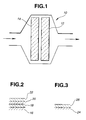
- this device 10 that is, an exhaust gas purifying catalyst or catalytic converter, preferably comprises a hydrocarbon-adsorbing-and-desorbing material and a NOx-adsorbing-and-reducing material (catalyst) arranged in the exhaust gas passage.
- the respective arrangements of these materials in the exhaust gas passage are not particularly limited. For example, it is preferable to dispose the NOx-adsorbing-and-reducing material downstream of the hydrocarbon-adsorbing-and-desorbing material in the exhaust gas passage.
- the NOx-adsorbing-and-reducing material and the hydrocarbon-adsorbing-and-desorbing material will also respectively be referred to as downstream and upstream catalysts 12, 14 (see Fig. 1).
- the hydrocarbon-adsorbing-and-desorbing material may efficiently adsorb or trap hydrocarbons, when the exhaust gas has a low temperature (e.g., less than 300°C), and then may desorb or release the adsorbed hydrocarbons at one time when the exhaust gas temperature increases to a temperature that is necessary for reducing NOx (e.g., at least 300°C).
- NOx is efficiently selectively reduced by the hydrocarbons desorbed from the hydrocarbon-adsorbing-and-desorbing material, at the NOx-adsorbing-and-reducing material, by arranging the NOx-adsorbing-and-reducing material downstream of the hydrocarbon-adsorbing-and-desorbing material.
- the hydrocarbon concentration of the exhaust gas may be varied or increased at an inlet of the NOx-adsorbing-and-reducing material (catalyst) by desorbing hydrocarbons from the hydrocarbon-adsorbing-and-desorbing material. Then, the desorbed hydrocarbons may efficiently selectively be brought into contact with NOx adsorbed on the NOx-adsorbing-and-reducing material.
- the desorbed hydrocarbons may not be oxidized by oxygen of the exhaust gas, but may selectively be oxidized by the adsorbed NOx, even though the exhaust gas contains an excessive amount of oxygen (e.g., A/F is at least 18), and at the same time the NOx may be reduced to N 2 .
- A/F excessive amount of oxygen
- the volume ratio of the upstream catalyst to the downstream catalyst is preferably within a range from 1:6 to 1:1.
- the NOx purification capability of the catalytic converter improves particularly. If it is less than 1:6, the hydrocarbon trap effect may become insufficient. If it is greater than 1:1, heat capacity of the upstream catalyst may become too large. This may interfere with the activity of the downstream catalyst in reducing NOx at a low temperature.
- the conditions for using the device 10 are not particularly limited.
- the device is capable of purifying an oxygen-rich exhaust gas exhausted from an engine driven with an air-fuel ratio (A/F) of at least 14.7 (14.7 is the stoichiometric A/F), particularly an A/F of at least 18.
- This exhaust gas, which is to be purified by the device 10 may contain hydrocarbons, carbon monoxide, NOx, etc. and has an oxygen concentration of at least 5%, a molar ratio of hydrocarbons to NOx of up to 10, and a low temperature of about 100-450°C.
- the exhaust gas has a too-low oxygen concentration and a too-high hydrocarbon concentration, so-called “caulking" on the catalyst surface (i.e., hydrocarbon deposition on the catalyst surface) may occur. This may accelerate catalyst deterioration.
- an exhaust gas that is always on the lean side, particularly that from an engine always driven with an A/F of at least 18, can effectively be purified by the device 10 of the present invention.
- a hydrocarbon(s) as a reducing agent into a lean-burn exhaust gas.
- a fuel-rich exhaust gas caused by the acceleration, etc. can also be purified by the device 10.
- the upstream and downstream catalysts may be prepared by forming catalytic coatings on honeycomb monolithic substrates, respectively.
- the material of each substrate is not particularly limited. It may be a ceramic (e.g., cordierite) or metal material (e.g., ferrite-based stainless steel).
- a honeycomb shape catalyst is particularly preferably as an automotive catalyst, which is used under a certain vibration and is required to treat a large amount of exhaust gas in a limited space. It is easy to prepare a multilayered catalytic coating, which has a plurality of layers having different functions, by forming the coating on a honeycomb shape substrate.
- the number of the upstream and downstream catalysts is not particularly limited, so long as the device has at least one upstream catalyst and at least one downstream catalyst.
- the device may have two downstream catalysts per one upstream catalyst.
- the device may have at least two pairs of upstream and downstream catalysts.
- the upstream catalyst 14 adsorbs hydrocarbons of the exhaust gas at a first temperature lower than T°C that is within the above-mentioned NO 2 -forming temperature range and desorbs the hydrocarbons at a second temperature that is not lower than T°C.
- the downstream catalyst 12 adsorbs NOx of the exhaust gas within the NO 2 -forming temperature range and is capable of accelerating a reduction of the NOx into N 2 at a third temperature that is not lower than T°C.
- the capability of reducing NOx of the downstream catalyst does not, however, depend on the NO 2 -forming temperature range.
- the NO 2 -forming temperature range is preferably lower than 350°C.
- the device for purifying an exhaust gas preferably comprises a hydrocarbon-adsorbing-and-desorbing material (upstream catalyst), which adsorbs hydrocarbons at a temperature range lower than 300°C and desorbs the hydrocarbons at a temperature range not lower than 300°C, and a NOx-adsorbing-and-reducing material (downstream catalyst), which adsorbs NOx at a temperature range lower than 300°C and accelerates the NOx reduction at a temperature range not lower than 300°C.
- upstream catalyst hydrocarbon-adsorbing-and-desorbing material
- downstream catalyst NOx-adsorbing-and-reducing material
- NOx is effectively reduced by the desorbed hydrocarbons.
- the NOx adsorbed on the downstream catalyst is assumed to have a higher reactivity, such that this NOx is assumed to be easily reduced by the desorbed hydrocarbons.
- NOx is removed basically by adsorption.
- the hydrocarbon-adsorbing-and-desorbing material of the upstream catalyst preferably comprises at least one zeolite selected from the group consisting of MFI zeolite, Y-type zeolite, mordenite, and ⁇ -zeolite.
- the at least one zeolite is capable of efficiently adsorbing hydrocarbons.
- Y-type zeolites USY-type zeolite is preferably used for the purpose of improving the catalyst in hydrothermal resistance.
- Each zeolite used in the invention is preferably subjected to hydrothermal treatment, re-synthesis, and the like, in order to increase crystallinity. With this, it may become possible to obtain a catalyst that is high in heat resistance and durability.
- the above-mentioned MFI zeolite, Y-type zeolite, mordenite, and ⁇ -zeolite are respectively preferably within ranges of 20-1,000, 4-50, 9-25, and 20-150, with respect to the molar ratio of silica to alumina of these zeolites. If the ratio is lower than the corresponding range, the zeolite skeleton may become unstable. If the ratio is higher than the corresponding range, the zeolite may become insufficient in retention of hydrocarbons. Thus, the zeolite of the upstream catalyst may not sufficiently retain hydrocarbons until the downstream catalyst starts the NOx reduction.
- the at least one zeolite of the upstream catalyst is preferably in an amount of 30-300 g per liter of the upstream catalyst. With this, the upstream catalyst does not become too large in heat capacity and thus does not interfere with the activity of the downstream catalyst.
- the at least one zeolite of the upstream catalyst supports thereon a NOx-reducing component that is at least one metal selected from the group consisting of copper, cobalt, iron, manganese, silver, indium, iridium, and rhodium.
- a NOx-reducing component that is at least one metal selected from the group consisting of copper, cobalt, iron, manganese, silver, indium, iridium, and rhodium.
- the amount of the NOx-reducing component is preferably from 1 to 20 wt%. With this, NOx can more efficiently be purified upon the desorption of hydrocarbons from the zeolite of the upstream catalyst.
- This phosphate may be at least one phosphate of at least one element selected from the group consisting of Cu, Ag, Mg, Zn, Sn, Cr, Mo, W, Mn, Co, and Ni.
- the phosphate of the upstream catalyst serves to modify the adsorbed hydrocarbons, particularly so-called “heavy hydrocarbons” having a larger number of carbons in the molecule(s), into “light hydrocarbons” that have a smaller number of carbons and thus are more active in the NOx reduction than the heavy hydrocarbons, through partial oxidation or oxidative dehydrogenation of the heavy hydrocarbons.
- the additive of the upstream catalyst is preferably loaded on a refractory inorganic support having a specific surface area of at least 60 m 2 /g.
- the refractory inorganic support may be at least one inorganic oxide selected from alumina, silica, zeolite, magnesia, titania, and zirconia. In fact, it is optional to use a binary inorganic oxide, such as silica-alumina, alumina-zirconia, or alumina-magnesia. It is preferable to use zeolite, particularly MFI zeolite or mordenite, as a refractory inorganic support for loading thereon the NOx-reducing component.
- metals used therefor may be in the form of mineral salt, carbonate, ammonium salt, organic salt (salt of organic acid), oxide, sodium salt, ammine complex, etc.
- such metal is preferably in the form of a water-soluble salt, in order to improve the catalytic capability.
- the method of loading the metal on a support in the preparation of the catalyst is not particularly limited, and may be one of conventional methods, such as drying through evaporation, deposition, impregnation, and ion-exchange, so long as the distribution of the metal on the support does not become substantially lopsided.
- ion-exchange in loading a metal on zeolite, in order to obtain a sufficient dispersibility of the metal thereon.
- the metal may be dissolved in a solution. It is optional to adjust pH of this solution by adding an acid or base thereto. By adjusting pH, it may be possible to regulate the condition of the metal loaded on support and obtain a sufficient heat resistance.
- the catalyst obtained by loading at least one metal on a support may be ground into a powder and then formed into a slurry. This slurry may be applied to a catalyst substrate, followed by heating at a temperature of 400-900°C, thereby to obtain a catalytic converter of the invention.
- the upstream catalyst may be prepared by forming on a substrate a first refractory inorganic oxide layer loaded with the above-mentioned phosphate, and then by forming on the first layer a second refractory inorganic oxide layer loaded with the above-mentioned NOx-reducing component.
- the resultant laminate of the first and second layers is capable of making each of the NOx-reducing component and phosphate function effectively.
- "heavy hydrocarbons" adsorbed on the first layer is modified into "light hydrocarbons" by the phosphate of the first layer, and the light hydrocarbons desorbed from the first layer reduce NOx in the presence of the NOx-reducing component upon passing through the second layer. It is not preferable to reverse the order of the first and second layers.
- the light hydrocarbons are released from the first layer loaded with the phosphate, which first layer is formed on the second layer, into the gas phase, without passing through the second layer loaded with the NOx-reducing component.
- the light hydrocarbons are not effectively used in reducing NOx.
- a downstream catalyst 12 (NOx-adsorbing-and-reducing catalyst) according to a first preferred embodiment of the present invention will be described in detail in the following.
- this downstream catalyst 12 comprises a substrate 16 and a laminate of first, second and third catalytic layers 18, 20, 22.
- the first layer 18 is formed on the substrate 16 and contains (1) at least one first component (noble metal) selected from Pt, Pd,and Rh and (2) at least one second component selected from alkali metals, alkali earth metals, and rare earth elements. Due to the addition of the at least one noble metal, the first layer is provided with oxidation power for oxidizing NO to NO 2 .
- this NO 2 is absorbed into the first layer, for example, in the form of Ba(NO 3 ) 2 , by removing an excess of the reducing gas component (hydrocarbons).
- the amount of hydrocarbons is excessive, for example, Ba(NO 3 ) 2 is decomposed into Ba and NO 2 .
- the amount of the at least one noble metal is not particularly limited, so long as it becomes possible to obtain a sufficient NOx absorption capability and a sufficient three-way catalytic capability.
- the amount of the at least one noble metal is preferably from 0.1 to 10 g per liter of the downstream catalyst. If it is less than 0.1 g, the three-way catalyst capability may become insufficient.
- an amount greater than 10 g may not bring about a significant advantage(s). It is preferable that the amount of the at least one second component is greater than 0.1 mol and up to 0.6 mol per liter of the downstream catalyst. If it is not greater than 0.1 mol, the amount of NOx absorption may become insufficient. If it is greater than 0.6 mol, the advantageous effect of the addition of the at least one noble metal may be impaired.
- the at least one second component it is preferable to use potassium, lithium, and sodium (sodium is particularly preferable) as the alkali metals; and barium, strontium, calcium,and magnesium as the alkali earth metals; and Y, La, Cs, Ce, Pr, Nd, Pm,and Sm (Cs and Ce are particularly preferable) as the rare earth elements.
- the first catalytic layer may have a function of oxidizing a NOx into another NOx that has a higher reactivity. Thus, it may increase the activity of a NOx reducing material of the third catalytic layer at a low temperature.
- the downstream catalyst 12 comprises the second catalytic layer 20 formed on the first catalytic layer 18 (see Figs. 1 and 2).
- the second catalytic layer 20 contains alumina and/or silica and is provided in order to separate the first and third catalytic layers 18, 22.
- the second layer is preferably substantially free of noble metal. Due to the provision of the second layer, it becomes possible to improve the active components of the first and third layers in thermal stability and thus improve the downstream catalyst in durability. If the second layer is omitted, the active components of the first and third layers may react together by the direct contact of these layers. This may make the first and third layers inferior in catalytic activity.
- the amount of the second layer is preferably from 20 to 100 g per liter of the downstream catalyst. If it is less than 20 g, the second layer may not properly function as a separation layer. If it is greater than 100 g, the exhaust gas may not easily reach the first layer by diffusion.
- the downstream catalyst 12 comprises the third catalytic layer 22 formed on the second layer 20 (see Figs. 1 and 2).
- the third catalytic layer 22 contains a zeolite having copper and/or cobalt.
- Nonlimitative examples of this zeolite are MFI-type zeolite, Y-type zeolite, mordenite, ferrierite, and ⁇ -type zeolite. Of these, MFI-type zeolite and ⁇ -type zeolite are preferable, due to their high NOx purification capability.
- the molar ratio of silica to alumina of the zeolite of the third layer is preferably from 20 to 80.
- the zeolite skeleton may become unstable. Furthermore, the amount of the Cu and/or Co loaded on the zeolite by ion exchange may become excessive. With this, dispersibility of the Cu and/or Co may become inferior, and thus the activity of one active site may substantially decrease. Furthermore, the active sites tend to cohere, for example, at a high temperature, thereby to make the third layer inferior in catalytic activity. This phenomenon is called "sintering". If the molar ratio is greater than 80, the number of the active sites may become too small. This may make the third layer insufficient in catalytic activity.
- the Cu and/or Co loaded on the zeolite serves to purify NOx of a lean-burn exhaust gas.
- the amount of the Cu and/or Co is preferably from 0.05 to 0.5 moles per liter of the downstream catalyst. Within this range, the sintering (cohesion of the active sites) does not easily occur by heat.
- the amount of the third layer is preferably from 120 to 300 g per liter of the downstream catalyst. If it is less than 120 g, the catalytic activity of the third layer may become insufficient when an exhaust gas passes through the downstream catalyst with a high space velocity. If it is greater than 300 g, the exhaust gas may not reach the first or second layer through diffusion. Furthermore, the pressure loss may become significant. Hydrocarbons desorbed from the upstream catalyst are efficiently trapped by the zeolite of the third layer, when the temperature of the exhaust gas is low.
- NOx reducing material Cu and/or Co
- NOx is acceleratingly reduced by the hydrocarbons. It becomes possible to more efficiently reduce NOx by the hydrocarbons, if the NOx reducing material is uniformly mixed with the zeolite.
- Hydrocarbons are modified in the first layer into activated hydrocarbons having a higher activity as a NOx reducing agent, and NOx is efficiently reduced by the activated hydrocarbons in the third layer.
- the upstream catalyst and the first catalytic layer of the downstream catalyst according to the first preferred embodiment may assist the third catalytic layer of the downstream catalyst in NOx oxidation, hydrocarbon adsorption, and hydrocarbon modification, when the third catalytic layer deteriorates under a hydrothermal condition.
- the catalytic converter according to the first preferred embodiment may suppress catalyst deterioration even under a hydrothermal condition (e.g., exposure to an atmosphere of at least 600°C containing steam).
- this downstream catalyst 12 comprises a substrate 24 and a catalytic layer 26 formed thereon.
- This catalytic layer may comprise a NOx reducing component, that is, Pt and/or Rh, for purifying NOx. It is optional to add a NOx adsorbing component (adsorbent) to the catalytic layer in order to improve NOx adsorption efficiency.
- This NOx adsorbent is selected from K, Na, Cs, Li, Ba, Ca, La, Y, Ce, and mixtures thereof.
- the NOx reducing component and/or the NOx adsorbing component may optionally be loaded on a refractory inorganic support, in order to improve their functions.
- This support may be the same as that for supporting thereon the additive of the upstream catalyst. Therefore, the detailed description relating to the refractory inorganic support will not be repeated here.
- An H-type ⁇ -zeolite having a molar ratio of SiO 2 to Al 2 O 3 of about 25, was mixed with an alumina sol and water, and this zeolite in the resultant mixture was ground for 20 min in a magnetic ball mill pot, thereby to obtain a slurry. Then, this slurry was applied to a cordierite monolithic (honeycomb) substrate having a volume of 1.0 liter and about 400 flow paths (cells) per 1 inch 2 of section. Then, the coated substrate was dried by hot air at 150°C and then baked at 500°C for 1 hr, thereby to obtain an upstream catalyst having about 150 g of the catalytic coating formed on the substrate, per liter of the substrate.
- An activated alumina powder was added to a dinitrodiammineplatinum aqueous solution. Then, the obtained mixture was stirred well, then dried for 8 hr at 120°C in a drier, and then baked for 2 hr at 500°C in an air stream, thereby to obtain a platinum-supported activated alumina powder.
- This catalytic powder contained about 1.0 wt% of platinum.
- water and an alumina sol acidified with nitric acid were added to the catalytic powder in a magnetic ball mill pot, and then it was driven for about 20 min for mixing and grinding, thereby to obtain a slurry of the Pt-supported activated alumina. This slurry contained 5 wt% of the alumina sol.
- this slurry was applied to a cordierite monolithic (honeycomb) substrate having a volume of 1.0 liter and about 400 flow paths (cells) per 1 inch 2 of section. Then, the coated substrate was dried by hot air at 150°C and then baked at 500°C for 1 hr, thereby to form about 35 g of a coating on the substrate, per liter of the substrate.
- the coated substrate was dipped in an aqueous solution containing calcium acetate, barium acetate and lanthanum nitrate, then withdrawn therefrom, then dried at 120°C, and then baked at 500°C for 1 hr, thereby to obtain a first catalytic layer containing 0.1 mol of calcium, 0.15 mol of barium and 0.1 mol of lanthanum, formed on the substrate.
- An alumina sol and water were added in a magnetic ball mill pot to an active alumina powder containing ⁇ -alumina as a main component, and then it was driven for about 20 min for mixing and grinding, thereby to obtain a slurry.
- This slurry contained 5 wt% of the alumina sol, based on an oxide (Al 2 O 3 ). Then, this slurry was applied to the substrate coated with the first catalytic layer. Then, the coated substrate was dried by hot air at 150°C and then baked at 500°C for 1 hr, thereby to form about 55 g of a second catalytic layer on the first catalytic layer, per liter of the substrate.
- An NH 4 -type MFI zeolite having a molar ratio of SiO 2 to Al 2 O 3 of about 35 was added to a 0.17-M aqueous solution containing therein copper nitrate and cobalt nitrate.
- This aqueous solution had a molar ratio of Cu to Co of 8.2.
- the obtained mixture was stirred well, and then a solid phase of the mixture was separated from a liquid phase thereof by filtration. This stirring and the subsequent separation were repeated three times, thereby to obtain a MFI zeolite cake having Cu and Co loaded thereon by ion exchange.
- this cake was dried at 120°C in a drier for a period of time of not less than 24 hr and then baked in an electric furnace at 600°C for 4 hr under a so-called "ambient condition" having the normal air composition and atmospheric pressure, thereby to obtain a MFI zeolite powder having 3.9 wt% of Cu and 0.8 wt% of Co, which are supported thereon.
- a catalytic converter according to the first preferred embodiment of the invention was obtained by repeating Example 1 except in that the NH 4 -type MFI zeolite used in the preparation of the third catalytic layer of the downstream catalyst was replaced with an NH 4 -type ⁇ -zeolite having a molar ratio of SiO 2 to Al 2 O 3 of about 42.
- a catalytic converter according to the first preferred embodiment of the invention was obtained by repeating Example 1 except in that the H-type ⁇ -zeolite used in the preparation of the upstream catalyst was replaced with an NH 4 -type Y-type zeolite having a molar ratio of SiO 2 to Al 2 O 3 of about 30.
- a catalytic converter according to the first preferred embodiment of the invention was obtained by repeating Example 1 except in that 1.0 wt% of platinum used in the preparation of the first catalytic layer of the downstream catalyst was replaced with a combination of 1.2 wt% of palladium and 0.2 wt% of rhodium.
- a catalytic converter according to the first preferred embodiment of the invention was obtained by repeating Example 1 except in that a combination of 0.1 mol of Ca, 0.15 mol of Ba and 0.1 mol of La, used in the preparation of the first catalytic layer of the downstream catalyst, was replaced with a combination of 0.01 mol of Mg, 0.1 mol of Ba and 0.01 mol of K.
- a catalytic converter according to the first preferred embodiment of the invention was obtained by repeating Example 1 except in that a combination of 0.1 mol of Ca, 0.15 mol of Ba and 0.1 mol of La, used in the preparation of the first catalytic layer of the downstream catalyst, was replaced with a combination of 0.2 mol of Ba, 0.05 mol of Sr, 0.04 mol of Cs and 0.29 mol of Ce.
- a catalytic converter according to the first preferred embodiment of the invention was obtained by repeating Example 1 except in that the NH 4 -type MFI zeolite powder used in the preparation of the third catalytic layer of the downstream catalyst was replaced with an H-type MFI zeolite having a molar ratio of SiO 2 to Al 2 O 3 of about 24.
- a catalytic converter according to the first preferred embodiment of the invention was obtained by repeating Example 1 except in that the NH 4 -type MFI zeolite powder used in the preparation of the third catalytic layer of the downstream catalyst was replaced with an H-type MFI zeolite having a molar ratio of SiO 2 to Al 2 O 3 of about 76.
- a catalytic converter according to the first preferred embodiment of the invention was obtained by repeating Example 1 except in that the activated alumina powder used in the preparation of the second catalytic layer of the downstream catalyst was replaced with a silica powder.
- a catalytic converter according to the first preferred embodiment of the invention was obtained by repeating Example 1 except in that the H-type ⁇ -zeolite powder used in the preparation of the upstream catalyst was replaced with an H-type MFI zeolite having a molar ratio of SiO 2 to Al 2 O 3 of about 35.
- a catalytic converter according to the first preferred embodiment of the invention was obtained by repeating Example 1 except in that the H-type ⁇ -zeolite powder used in the preparation of the upstream catalyst was replaced with an H-type mordenite having a molar ratio of SiO 2 to Al 2 O 3 of about 15.
- a catalytic converter according to the first preferred embodiment of the invention was obtained by repeating Example 1 except in that the H-type ⁇ -zeolite powder used in the preparation of the upstream catalyst was replaced with a mixture of 1 part by weight of an H-type ⁇ -zeolite having a molar ratio of SiO 2 to Al 2 O 3 of about 25 and 1 part by weight of an H-type MFI zeolite having a molar ratio of SiO 2 to Al 2 O 3 of about 700.
- a catalytic converter according to the first preferred embodiment of the invention was obtained by repeating Example 1 except in that the H-type ⁇ -zeolite powder used in the preparation of the upstream catalyst was replaced with a mixture of 2 parts by weight of an H-type ⁇ -zeolite having a molar ratio of SiO 2 to Al 2 O 3 of about 25, 1 part by weight of an H-type MFI zeolite having a molar ratio of SiO 2 to Al 2 O 3 of about 700, and 1 part by weight of an H-type Y-type zeolite having a molar ratio of SiO 2 to Al 2 O 3 of about 30.
- a catalytic converter according to the first preferred embodiment of the invention was obtained by repeating Example 1 except in that the amount of the catalytic coating of the upstream catalyst per liter of the substrate was changed from 150 g to 40 g.
- a catalytic converter according to the first preferred embodiment of the invention was obtained by repeating Example 1 except in that the amount of the catalytic coating of the upstream catalyst per liter of the substrate was changed from 150 g to 300 g.
- a catalytic converter according to the first preferred embodiment of the invention was obtained by repeating Example 1 except in that 1 part by volume of the upstream catalyst and 1 part by volume of the downstream catalyst were connected together.
- a catalytic converter according to the first preferred embodiment of the invention was obtained by repeating Example 1 except in that 1 part by volume of the upstream catalyst and 5 parts by volume of the downstream catalyst were connected together.
- a catalytic converter according to the first preferred embodiment of the invention was obtained by repeating Example 1 except in that 5 wt% of copper was loaded on the H-type ⁇ -zeolite powder by using a copper phosphate aqueous solution in the preparation of the upstream catalyst, prior to the mix of the H-type ⁇ -zeolite powder with the alumina sol and water.
- a catalytic converter according to the first preferred embodiment of the invention was obtained by repeating Example 1 except in that 5 wt% of iron was loaded on the H-type ⁇ -zeolite powder by using an iron phosphate aqueous solution in the preparation of the upstream catalyst, prior to the mix of the H-type ⁇ -zeolite powder with the alumina sol and water.
- a catalytic converter according to the first preferred embodiment of the invention was obtained by repeating Example 1 except in that 5 wt% of manganese was loaded on the H-type ⁇ -zeolite powder by using a manganese pyrophosphate aqueous solution in the preparation of the upstream catalyst, prior to the mix of the H-type ⁇ -zeolite powder with the alumina sol and water.
- a catalytic converter according to the first preferred embodiment of the invention was obtained by repeating Example 1 except in that 5 wt% of cobalt was loaded on the H-type ⁇ -zeolite powder by using a cobalt phosphate aqueous solution in the preparation of the upstream catalyst, prior to the mix of the H-type ⁇ -zeolite powder with the alumina sol and water.
- a catalytic converter was obtained by repeating Example 1 except in that the upstream catalyst was omitted.
- a catalytic converter was obtained by repeating Example 5 except in that a combination of 0.01 mol of Mg, 0.1 mol of Ba and 0.01 mol of K, used in the preparation of the first catalytic layer of the downstream catalyst, was replaced with a combination of 0.03 mol of Mg, 0.04 mol of Ba and 0.01 mol of K.
- a catalytic converter was obtained by repeating Example 6 except in that a combination of 0.2 mol of Ba, 0.05 mol of Sr, 0.04 mol of Cs, and 0.29 mol of Ce, used in the preparation of the first catalytic layer of the downstream catalyst, was replaced with a combination of 0.3 mol of Ba, 0.02 mol of Sr, 0.3 mol of Cs, and 0.01 mol of Ce.
- a catalytic converter was obtained by repeating Example 1 except in that the amount of the third catalytic layer of the downstream catalyst was 100 g per liter of the substrate.
- a catalytic converter was obtained by repeating Example 1 except in that the amount of the third catalytic layer of the downstream catalyst was 350 g per liter of the substrate.
- a catalytic converter was obtained by repeating Example 1 except in that the amount of the catalytic coating of the upstream catalyst was 20 g per liter of the substrate.
- a catalytic converter was obtained by repeating Example 1 except in that the amount of the catalytic coating of the upstream catalyst was 350 g per liter of the substrate.
- a catalytic converter was obtained by repeating Example 1 except in that an H-type ⁇ -zeolite having a molar ratio of SiO 2 to Al 2 O 3 of about 10 was used in the preparation of the upstream catalyst, in place of that having a molar ratio of SiO 2 to Al 2 O 3 of about 25.
- a catalytic converter was obtained by repeating Example 1 except in that an H-type ⁇ -zeolite having a molar ratio of SiO 2 to Al 2 O 3 of about 200 was used in the preparation of the upstream catalyst, in place of that having a molar ratio of SiO 2 to Al 2 O 3 of about 25.
- a catalytic converter was obtained by repeating Example 3 except in that an NH 4 -type Y-type zeolite having a molar ratio of SiO 2 to Al 2 O 3 of about 1.5 was used in the preparation of the upstream catalyst, in place of that having a molar ratio of SiO 2 to Al 2 O 3 of about 30.
- a catalytic converter was obtained by repeating Example 10 except in that an H-type MFI zeolite having a molar ratio of SiO 2 to Al 2 O 3 of about 10 was used in the preparation of the upstream catalyst, in place of that having a molar ratio of SiO 2 to Al 2 O 3 of about 35.
- a catalytic converter was obtained by repeating Example 11 except in that an H-type mordenite having a molar ratio of SiO 2 to Al 2 O 3 of about 7 was used in the preparation of the upstream catalyst, in place of that having a molar ratio of SiO 2 to Al 2 O 3 of about 15.
- a catalytic converter was obtained by repeating Example 1 except in that 2 parts by volume of the upstream catalyst and 1 part by volume of the downstream catalyst were connected together.
- a catalytic converter was obtained by repeating Example 1 except in that 1 part by volume of the upstream catalyst and 7 parts by volume of the downstream catalyst were connected together.
- a catalytic converter was obtained by repeating Example 1 except in that an NH 4 -type MFI zeolite having a molar ratio of SiO 2 to Al 2 O 3 of about 17 was used in the preparation of the third catalytic layer of the downstream catalyst, in place of that having a molar ratio of SiO 2 to Al 2 O 3 of about 35.
- a catalytic converter was obtained by repeating Example 1 except in that an NH 4 -type MFI zeolite having a molar ratio of SiO 2 to Al 2 O 3 of about 82 was used in the preparation of the third catalytic layer of the downstream catalyst, in place of that having a molar ratio of SiO 2 to Al 2 O 3 of about 35.
- each catalytic converter was arranged in the exhaust passage of an engine dynamometer having a 4-cylindered 2.5 liter diesel engine installed therein. Then, the engine was driven such that the exhaust gas of 630°C was allowed to pass through each catalytic converter for 30 hr. Then, the NOx concentration of the exhaust gas was measured at the inlet and the outlet of each catalytic converter at the same time with a NOx monitor, while the temperature of the inlet of each catalytic converter was increased from 100°C to 500°C at a rate of about 30°C per minute.
- NOx Conversion (%) [(a-b)/a] ⁇ 100 where "a" is the NOx concentration at the inlet of the catalytic converter (i.e., the inlet of the upstream catalyst), and "b” is the NOx concentration at the outlet of the catalytic converter (i.e., the outlet of the downstream catalyst).
- Example 15 Example 15 24.3 Example 16 21.3 Example 17 25.9 Example 18 32.1 Example 19 30.3 Example 20 31.4 Example 21 33.2 Com. Ex. 1 13.3 Com. Ex. 2 17.6 Com. Ex. 3 16.9 Com. Ex. 4 10.1 Com. Ex. 5 16.0 Com. Ex. 6 13.5 Com. Ex. 7 15.0 Com. Ex. 8 16.2 Com. Ex. 9 17.0 Com. Ex. 10 10.8 Com. Ex. 11 13.6 Com. Ex. 12 12.4 Com. Ex. 13 9.7 Com. Ex. 14 14.2 Com. Ex. 15 8.2 Com. Ex. 16 13.4
- a boehmite having a specific surface area of about 280 m 2 /g was added to a copper phosphate aqueous solution basified with ammonia. After that, the resultant mixture was stirred well, then dried at 120°C for a period of time of at least 24 hr, and then baked at 500°C for 2 hr, thereby to obtain a copper-phosphate-carried alumina powder. Then, 1 part by weight of this alumina powder was mixed with 1 part by weight of an H-type MFI zeolite powder having a molar ratio of silica to alumina of about 100.
- the obtained mixture was mixed with an alumina sol and water in a magnetic ball mill pot, and it was driven for about 30 min for mixing and grinding, thereby to obtain a slurry.
- the amount of the alumina sol on an oxide basis (Al 2 O 3 ) was 10 wt%, based on the total weight of the alumina powder and the H-type MFI zeolite.
- this slurry was applied to a cordierite monolithic (honeycomb) substrate having a volume of 0.8 liter and about 600 flow paths (cells) per 1 inch 2 of section.
- the coated substrate was dried by hot air at 150°C and then baked at 500°C for 1 hr, thereby to form about 120 g of a first catalytic layer on the substrate, per liter of the substrate.
- a 0.2-M copper nitrate aqueous solution was adjusted to have a pH of 9.5 by adding an aqueous ammonia thereto.
- an NH 4 -type MFI zeolite powder having a molar ratio of SiO 2 to Al 2 O 3 of about 45 was added.
- the obtained mixture was stirred well, and then a solid phase of the mixture was separated from a liquid phase thereof by filtration. This stirring and the subsequent separation were repeated three times, thereby to obtain a MFI zeolite cake having Cu loaded thereon by ion exchange.
- this cake was dried at 120°C in a drier for a period of time of not less than 24 hr and then baked in an electric furnace at 600°C for 4 hr under the ambient condition, thereby to obtain a MFI zeolite powder having 3.6 wt% of Cu supported thereon.
- the obtained MFI zeolite powder was mixed with an alumina sol and water in a magnetic ball mill pot, and then it was driven for 20 min for mixing and grinding, thereby to obtain a slurry.
- the amount of this alumina sol on an oxide basis (Al 2 O 3 ) was 10 wt%, based on the total weight of the MFI zeolite powder.
- the slurry was applied to the coated substrate having the first catalytic layer, and then the coated substrate was dried at 150°C by hot air and then baked at 500°C for 1 hr, thereby to obtain an upstream catalyst having about 100 g of a second catalytic layer formed on the first catalytic layer, per liter of the substrate.
- a boehmite having a specific surface area of about 280 m 2 /g was added to a lanthanum nitrate aqueous solution such that the molar ratio of lanthanum to aluminum of the resultant mixture was 3:97.
- This mixture was stirred well, then dried at 120°C for a period of time of at least 24 hr, and then baked at 500°C for 4 hr, thereby to obtain an alumina powder having lanthanum loaded thereon.
- This alumina powder was added to a dinitrodiammineplatinum aqueous solution containing about 4 wt% of Pt.
- the resultant mixture was stirred well, then dried at 120°C for a period of time of at least 24 hr, and then baked at 650°C for 4 hr, thereby to obtain an alumina powder having lanthanum and 2wt% of Pt, which are loaded thereon. Then, this alumina powder was mixed with water and an alumina sol acidified with nitric acid in a magnetic ball mill pot, and it was driven for 30 min for grinding, thereby to obtain a slurry. The amount of this alumina sol was 2 wt%, based on the total weight of the La-and-Pt-carried alumina powder.
- the slurry was applied to a cordierite monolithic (honeycomb) substrate having a volume of 1.2 liter and about 400 flow paths (cells) per 1 inch 2 of section. Then, the coated substrate was dried by hot air at 150°C and then baked at 500°C for 1 hr, thereby to obtain an downstream catalyst having about 160 g of the catalytic coating formed on the substrate, per liter of the substrate.
- a catalytic converter having a total catalyst volume of 2.0 liter, was prepared by connecting the upstream and downstream catalysts together in-line.
- An upstream catalyst was prepared in the same manner as that of Example 22 except in that the copper phosphate was replaced with zinc phosphate, that the H-type MFI zeolite having a molar ratio of SiO 2 to Al 2 O 3 of about 100 was replaced with a mixture of 2 parts by weight of an H-type mordenite having a molar ratio of SiO 2 to Al 2 O 3 of about 40 and 1 part by weight of a Y-type zeolite having a molar ratio of SiO 2 to Al 2 O 3 of about 40, and that the copper nitrate aqueous solution was replaced with an aqueous solution containing silver nitrate and cobalt nitrate. This aqueous solution was the same as that of the copper nitrate aqueous solution in concentration.
- the obtained MFI zeolite contained 3.2 wt% of Ag and 0.3 wt% of Co, which were loaded thereon.
- a downstream catalyst was prepared in the same manner as that of Example 22 except in that the lanthanum was replaced with a mixture of 0.5 parts by mol of calcium, 2 parts by mol of sodium and 1 part by mol of cerium, and that the boehmite was replaced with a titanium-silica mixture having a specific surface area of about 90 m 2 /g.
- a catalytic converter was prepared in the same manner as that of Example 22.
- An upstream catalyst was prepared in the same manner as that of Example 22 except in that the copper phosphate was replaced with a mixture of 4 parts by weight of nickel phosphate, 1 part by weight of tin phosphate and 1 part by weight of molybdenum phosphate, that the H-type MFI zeolite powder having a molar ratio of SiO 2 to Al 2 O 3 of about 100 was replaced with an H-type ⁇ -zeolite powder having a molar ratio of SiO 2 to Al 2 O 3 of about 150, and that the copper nitrate aqueous solution was replaced with an aqueous solution containing cobalt nitrate, indium nitrate and iridium nitrate.
- This aqueous solution was the same as that of the copper nitrate aqueous solution in concentration.
- the obtained MFI zeolite contained 2.0 wt% of cobalt, 0.5 wt% of indium and 0.8 wt% of iridium, which were loaded thereon.
- a downstream catalyst was prepared in the same manner as that of Example 22 except in that the lanthanum was replaced with a mixture of 0.1 parts by mol of potassium, 0.2 parts by mol of barium and 3 parts by mol of lanthanum, and that the boehmite was replaced with an alumina-zirconia-magnesia mixture having a specific surface area of about 240 m 2 /g. In fact, this mixture contained 95 parts by mol of A1, 3 parts by mol of Zr and 2 parts by mol of Mg.
- a catalytic converter was prepared in the same manner as that of Example 22.
- An upstream catalyst was prepared in the same manner as that of Example 22 except in that the copper phosphate was replaced with a mixture of 3 parts by weight of tungsten phosphate, 1 part by weight of manganese phosphate and 1 part by weight of cobalt phosphate, and that the copper nitrate aqueous solution was replaced with an aqueous solution containing iridium nitrate and rhodium nitrate. This aqueous solution was the same as that of the copper nitrate aqueous solution in concentration.
- the obtained MFI zeolite contained 0.5 wt% of iridium and 0.8 wt% of rhodium, which were loaded thereon.
- a downstream catalyst was prepared in the same manner as that of Example 22 except in that the lanthanum was replaced with a mixture of 0.1 parts by mol of cesium, 0.1 parts by mol of lithium and 3 parts by mol of lanthanum, and that the boehmite was replaced with an alumina-zirconia mixture having a specific surface area of about 270 m 2 /g. In fact, this mixture contained 97 parts by mol of A1 and 3 parts by mol of Zr.
- a catalytic converter was prepared in the same manner as that of Example 22.
- a zeolite powder mixture was prepared by mixing 3 parts by weight of an H-type MFI zeolite powder having a molar ratio of silica to alumina of about 80 with 5 parts by weight of an H-type ⁇ -zeolite having a molar ratio of silica to alumina of about 50.
- the zeolite powder mixture was mixed with an alumina sol and water in a magnetic ball mill pot, and it was driven for about 60 min for mixing and grinding, thereby to obtain a slurry.
- the amount of the alumina sol on an oxide basis (Al 2 O 3 ) was 10 wt%, based on the total weight of the zeolite powder mixture.
- this slurry was applied to a cordierite monolithic (honeycomb) substrate having a volume of 0.8 liter and about 600 flow paths (cells) per 1 inch 2 of section. Then, the coated substrate was dried by hot air at 150°C and then baked at 500°C for 1 hr, thereby to obtain an upstream catalyst having about 180 g of a catalytic layer on the substrate, per liter of the substrate.
- a downstream catalyst having a volume of 1.2 liter was prepared in the same manner as that of Example 22.
- a catalytic converter having a total catalyst volume of 2.0 liter, was prepared by connecting the upstream and downstream catalysts together in-line.
- a catalytic converter was prepared in the same manner as that of Example 22 except in that the volume of the upstream catalyst was 2.0 liter in place of 0.8 liter and that the downstream catalyst was omitted.
- a catalytic converter was prepared in the same manner as that of Example 22 except in that the volume of the downstream catalyst was 2.0 liter in place of 1.2 liter and that the upstream catalyst was omitted.
- a catalytic converter was prepared in the same manner as that of Example 22 except in that the relative positions of the upstream and downstream catalysts were reversed. In other words, a catalytic converter was prepared by arranging the downstream catalyst of Example 22 upstream of the upstream catalyst of Example 22.
- each catalytic converter was arranged in the exhaust passage of an engine dynamometer having a 4-cylindered 2.5 liter direct-injection diesel engine installed therein. Then, the engine was driven such that the exhaust gas of 600°C was allowed to pass through each catalytic converter for 100 hr in order to conduct a pretreatment of the catalytic converter. Then, the NOx concentration of the exhaust gas was measured at the inlet and the outlet of each catalytic converter with a NOx monitor, while the temperature of the inlet of each catalytic converter was maintained at 150°C for 5 min, then increased to 450°C by spending about 3 min, and then maintained at 450°C for 5 min.
- the temperature of the inlet of each catalytic converter was regulated as above by adjusting the engine load.
- the gas space velocity was adjusted to about 35,000 h -1 , and the average molar ratio of hydrocarbons to NOx of the exhaust gas was about 4.
- the molar ratio of hydrocarbons to NOx of the exhaust gas during the temperature increase to 450°C was about 1.2.
- the NOx conversion of each catalytic converter during the temperature increase was determined in the same manner as in the first catalytic-activity evaluation test, and the results are shown in Table 4.
- the N 2 O concentration of the exhaust gas was measured with an N 2 O monitor at a position downstream of each catalytic converter.
- Fig. 4 shows the variation of the percentage of the removal of hydrocarbons and NOx from the exhaust gas with the catalyst temperature of the catalytic converter according to Example 26.
- the solid line of Fig. 4 shows the variation of the percentage of the removal of hydrocarbons from the exhaust gas with the temperature of the upstream catalyst of Example 26, and the dotted line of Fig. 4 shows that of NOx from the exhaust gas with the temperature of the downstream catalyst of Example 26.
- the removal of hydrocarbons and NOx from the exhaust gas means the adsorption of these gas components on the upstream and downstream catalysts and the chemical changes of these gas components into other gas components (e.g., H 2 O, CO 2 and N 2 ).
- the removal percentage of hydrocarbons is relatively high, that is, a relatively large amount of hydrocarbons is removed from the exhaust gas by adsorption on the upstream catalyst, until the temperature of the upstream catalyst increases to about 250°C.
- the temperature of the upstream catalyst farther increases from about 250°C over about 300°C towards about 350°C, the removal percentage of hydrocarbons from the exhaust gas decreases sharply. This means that the amount of hydrocarbons in the exhaust gas increases sharply due to desorption of hydrocarbons from the upstream catalyst.
- the removal percentage of hydrocarbons from the exhaust gas increases sharply, due to the combustion (decomposition) of hydrocarbons.
- the removal percentage of NOx is relatively high due to adsorption on the downstream catalyst, until the temperature of the downstream catalyst increases to about 300°C. As the temperature of the downstream catalyst farther increases over about 300°C, the removal percentage of NOx from the exhaust gas decreases. This means that the amount of NOx in the exhaust gas increases due to desorption of NOx from the downstream catalyst. The amount of the NOx desorption becomes maximum when the temperature of the downstream catalyst is about 400°C. It is understood from Fig. 4 that the desorption of hydrocarbons from the upstream catalyst occurs at a temperature lower than the temperature at which the desorption of NOx from the downstream catalyst occurs.
- the desorption of hydrocarbons from the upstream catalyst occurs prior to the desorption of NOx from the downstream catalyst.
- the desorbed hydrocarbons can be brought into contact with the adsorbed NOx.
- the desorbed hydrocarbons may react selectively with the NOx, thereby to reduce the NOx into N 2 .
Landscapes
- Chemical & Material Sciences (AREA)
- Engineering & Computer Science (AREA)
- Chemical Kinetics & Catalysis (AREA)
- Combustion & Propulsion (AREA)
- Materials Engineering (AREA)
- General Engineering & Computer Science (AREA)
- Mechanical Engineering (AREA)
- Organic Chemistry (AREA)
- Biomedical Technology (AREA)
- Oil, Petroleum & Natural Gas (AREA)
- General Chemical & Material Sciences (AREA)
- Analytical Chemistry (AREA)
- Environmental & Geological Engineering (AREA)
- Health & Medical Sciences (AREA)
- Exhaust Gas Treatment By Means Of Catalyst (AREA)
- Catalysts (AREA)
- Exhaust Gas After Treatment (AREA)
Abstract
Description
- The present invention relates to a device for purifying oxygen rich exhaust gas and in particular to a catalyst (catalytic converter) that is capable of removing NOx contained in the oxygen rich exhaust gas.
- There has been a strong demand for lean-burn automobiles. Such a lean-burn automobile is driven on the lean side with a large air-fuel ratio (A/F) during ordinary driving, so as to burn an oxygen rich air-fuel mixture and thereby meet with the demands for lower fuel consumption. In case of an oxygen rich (lean) air-fuel mixture, the oxygen content of the exhaust gas after combustion becomes high. If this exhaust gas is allowed to flow through a conventional three-way catalyst, the oxidation action becomes more active and the reduction action becomes inactive. That is, it becomes easy to oxidize hydrocarbons (HC) and carbon monoxide (CO) into CO2 and H2O by oxygen, but it becomes difficult to reduce NOx into N2 in an oxygen-rich exhaust gas. In view of this, it has been desired to provide a catalyst that can efficiently remove NOx from an exhaust gas on the lean side, that is, an oxygen rich exhaust gas.
- Each of JP-A-1-127044 and JP-A-5-68888 discloses an exhaust gas purifying catalyst having a first layer containing a catalytic component (noble metal) and a second layer containing zeolite. JP-A-1-310742 discloses another zeolite catalytic layer containing copper by ion exchange and noble metal. JP-5-168939 discloses another catalyst containing a metal-containing silicate having noble and transition metals loaded thereon. Heisei-9th (1997) Shokubai Kenkyu Happyoukai (Presentation of Catalyst Studies) Koen Yokoushu (Proceeding) 3A01, pp. 61 discloses that cobalt phosphate, loaded with Pt, and gallium phosphate each have NOx reducing activity. JP-A-6-55075 discloses an exhaust gas purifying catalyst made of a phosphate loaded with at least one metal having a catalytic activity. JP-A-4-83516 discloses a method for removing NOx by using a first catalytic layer, in which fuel is introduced and decomposed, and a second catalytic layer, where NOx is decomposed in the presence of the decomposed fuel. JP-A-6-146869 discloses an exhaust gas purifying device having a hydrocarbon adsorbent disposed downstream of a NOx reducing catalyst. JP-A-10-57763 discloses an exhaust gas purifying catalyst in which a hydrocarbon adsorbing layer is interposed between a substrate and a catalyst loaded layer. JP-A-5-321655 discloses a method for purifying a diesel engine exhaust gas, in which a first catalyst, having a transition-metal-containing crystalline silicate, and a second three-way catalyst are disposed in the exhaust passage. JP-A-7-19031 discloses an exhaust gas purifying device having a NOx reducing catalyst, a hydrocarbon adsorbent, and a means for adding hydrocarbons. Each of JP-A-7-124479 and JP-A-7-144134 discloses an exhaust gas purifying catalyst containing a crystalline aluminosilicate (zeolite) having Cu and at least one selected from B, P, Sb, and Bi. JP-B2-2600492 discloses an exhaust gas purifying device having a NOx adsorbent that absorbs NOx on the lean side and releases the absorbed NOx when the oxygen concentration of the exhaust gas is lowered.
- It is an object of the present invention to provide a device for purifying an exhaust gas, which device is capable of purifying NOx contained in an oxygen rich exhaust gas, when the exhaust gas temperature and the HC/NOx ratio of the exhaust gas are each low.
- According to the present invention, there is provided a device for purifying an exhaust gas. This device comprises a NOx-adsorbing-and-reducing material (catalyst) that is capable of adsorbing a NOx and accelerating a reduction of the adsorbed NOx into N2, within a NO2-forming temperature range where a reaction represented by the following formula (1) proceeds,
-
- Fig. 1 is a sectional view showing an exemplary catalytic converter according to the present invention, having upstream and downstream catalysts;
- Fig. 2 is an enlarged sectional view showing an exemplary downstream catalyst according to a first preferred embodiment of the present invention, having first, second,and third catalytic layers formed on a substrate;
- Fig. 3 is a view similar to Fig. 2, but showing another exemplary downstream catalyst according to a second preferred embodiment of the present invention, having a single catalytic layer formed on a substrate; and
- Fig. 4 is a graph showing the variation of the percentage of the removal of hydrocarbons (HC) and NOx from the exhaust gas with the catalyst temperature of the catalytic converter according to Example 26.
-
- A device for purifying an exhaust gas according to the present invention will be described in detail in the following. As is seen from Fig. 1, this
device 10, that is, an exhaust gas purifying catalyst or catalytic converter, preferably comprises a hydrocarbon-adsorbing-and-desorbing material and a NOx-adsorbing-and-reducing material (catalyst) arranged in the exhaust gas passage. The respective arrangements of these materials in the exhaust gas passage are not particularly limited. For example, it is preferable to dispose the NOx-adsorbing-and-reducing material downstream of the hydrocarbon-adsorbing-and-desorbing material in the exhaust gas passage. Thus, hereinafter, the NOx-adsorbing-and-reducing material and the hydrocarbon-adsorbing-and-desorbing material will also respectively be referred to as downstream andupstream catalysts 12, 14 (see Fig. 1). The hydrocarbon-adsorbing-and-desorbing material may efficiently adsorb or trap hydrocarbons, when the exhaust gas has a low temperature (e.g., less than 300°C), and then may desorb or release the adsorbed hydrocarbons at one time when the exhaust gas temperature increases to a temperature that is necessary for reducing NOx (e.g., at least 300°C). NOx is efficiently selectively reduced by the hydrocarbons desorbed from the hydrocarbon-adsorbing-and-desorbing material, at the NOx-adsorbing-and-reducing material, by arranging the NOx-adsorbing-and-reducing material downstream of the hydrocarbon-adsorbing-and-desorbing material. In other words, the hydrocarbon concentration of the exhaust gas may be varied or increased at an inlet of the NOx-adsorbing-and-reducing material (catalyst) by desorbing hydrocarbons from the hydrocarbon-adsorbing-and-desorbing material. Then, the desorbed hydrocarbons may efficiently selectively be brought into contact with NOx adsorbed on the NOx-adsorbing-and-reducing material. Therefore, the desorbed hydrocarbons may not be oxidized by oxygen of the exhaust gas, but may selectively be oxidized by the adsorbed NOx, even though the exhaust gas contains an excessive amount of oxygen (e.g., A/F is at least 18), and at the same time the NOx may be reduced to N2. Similar to the above, it is optional to vary the concentration of carbon monoxide or that of hydrocarbons and carbon monoxide of the exhaust gas at an inlet of the NOx-adsorbing-and-reducing catalyst, in order to efficiently selectively reduce the adsorbed NOx by carbon monoxide or a combination of hydrocarbons and carbon monoxide. The volume ratio of the upstream catalyst to the downstream catalyst is preferably within a range from 1:6 to 1:1. Within this range, the NOx purification capability of the catalytic converter improves particularly. If it is less than 1:6, the hydrocarbon trap effect may become insufficient. If it is greater than 1:1, heat capacity of the upstream catalyst may become too large. This may interfere with the activity of the downstream catalyst in reducing NOx at a low temperature. - The conditions for using the
device 10 are not particularly limited. The device is capable of purifying an oxygen-rich exhaust gas exhausted from an engine driven with an air-fuel ratio (A/F) of at least 14.7 (14.7 is the stoichiometric A/F), particularly an A/F of at least 18. This exhaust gas, which is to be purified by thedevice 10, may contain hydrocarbons, carbon monoxide, NOx, etc. and has an oxygen concentration of at least 5%, a molar ratio of hydrocarbons to NOx of up to 10, and a low temperature of about 100-450°C. If the exhaust gas has a too-low oxygen concentration and a too-high hydrocarbon concentration, so-called "caulking" on the catalyst surface (i.e., hydrocarbon deposition on the catalyst surface) may occur. This may accelerate catalyst deterioration. It is possible to use the catalytic converter of the invention for a long time with a high exhaust-gas purification capability by adjusting the exhaust gas to have an oxygen concentration of at least 5% and a molar ratio of hydrocarbons to NOx of up to 10. According to the invention, it is not necessary to intentionally adjust the A/F to the stoichiometric A/F or the rich side for the purpose of reducing NOx. In other words, an exhaust gas that is always on the lean side, particularly that from an engine always driven with an A/F of at least 18, can effectively be purified by thedevice 10 of the present invention. Furthermore, it is not necessary to add a hydrocarbon(s) as a reducing agent into a lean-burn exhaust gas. It should be noted that a fuel-rich exhaust gas caused by the acceleration, etc. can also be purified by thedevice 10. The upstream and downstream catalysts may be prepared by forming catalytic coatings on honeycomb monolithic substrates, respectively. The material of each substrate is not particularly limited. It may be a ceramic (e.g., cordierite) or metal material (e.g., ferrite-based stainless steel). It is optional to form catalytic coatings themselves of the upstream and downstream catalysts into honeycomb shape. If the upstream and downstream catalysts are in honeycomb shape, the contact area between the catalyst and an exhaust gas becomes substantially large. Furthermore, the pressure loss does not become so large. Therefore, a honeycomb shape catalyst is particularly preferably as an automotive catalyst, which is used under a certain vibration and is required to treat a large amount of exhaust gas in a limited space. It is easy to prepare a multilayered catalytic coating, which has a plurality of layers having different functions, by forming the coating on a honeycomb shape substrate. The number of the upstream and downstream catalysts is not particularly limited, so long as the device has at least one upstream catalyst and at least one downstream catalyst. For example, the device may have two downstream catalysts per one upstream catalyst. Furthermore, the device may have at least two pairs of upstream and downstream catalysts. - The
upstream catalyst 14 adsorbs hydrocarbons of the exhaust gas at a first temperature lower than T°C that is within the above-mentioned NO2-forming temperature range and desorbs the hydrocarbons at a second temperature that is not lower than T°C. Thedownstream catalyst 12 adsorbs NOx of the exhaust gas within the NO2-forming temperature range and is capable of accelerating a reduction of the NOx into N2 at a third temperature that is not lower than T°C. The capability of reducing NOx of the downstream catalyst does not, however, depend on the NO2-forming temperature range. The NO2-forming temperature range is preferably lower than 350°C. It is preferable to select a suitable hydrocarbon-adsorbing-and-desorbing material as the upstream catalyst, depending on the type of hydrocarbons contained in the exhaust gas, in order to adjust the above-mentioned T°C to be lower than 300°C. - As mentioned above, the device for purifying an exhaust gas according to the present invention preferably comprises a hydrocarbon-adsorbing-and-desorbing material (upstream catalyst), which adsorbs hydrocarbons at a temperature range lower than 300°C and desorbs the hydrocarbons at a temperature range not lower than 300°C, and a NOx-adsorbing-and-reducing material (downstream catalyst), which adsorbs NOx at a temperature range lower than 300°C and accelerates the NOx reduction at a temperature range not lower than 300°C. In fact, when an exhaust gas flowing through the upstream catalyst has a temperature lower than 300°C, such as shortly after the cold-start of the engine, the amount of hydrocarbons flowing towards the downstream catalyst decreases due to the adsorption of hydrocarbons on the upstream catalyst. Under this condition, a substantially large amount of NOx is adsorbed on the downstream catalyst, thereby to highly effectively remove NOx from a low-temperature exhaust gas. When an exhaust gas flowing through the upstream catalyst has a temperature not lower than 300°C, hydrocarbons desorbed from the upstream flows through the downstream catalyst. With this, these hydrocarbons are brought into contact with the adsorbed NOx in the downstream catalyst. Upon this, the molar ratio of HC/NOx becomes substantially high on the surface of the downstream catalyst. Therefore, NOx is effectively reduced by the desorbed hydrocarbons. The NOx adsorbed on the downstream catalyst is assumed to have a higher reactivity, such that this NOx is assumed to be easily reduced by the desorbed hydrocarbons. When an exhaust gas flowing through the upstream catalyst has a temperature lower than 300°C, NOx is removed basically by adsorption. Thus, even if a Pt-based catalyst is used in the downstream catalyst, it becomes possible to suppress the generation of N2O, which is one of global warming gases.
- The hydrocarbon-adsorbing-and-desorbing material of the upstream catalyst preferably comprises at least one zeolite selected from the group consisting of MFI zeolite, Y-type zeolite, mordenite, and β-zeolite. The at least one zeolite is capable of efficiently adsorbing hydrocarbons. Of Y-type zeolites, USY-type zeolite is preferably used for the purpose of improving the catalyst in hydrothermal resistance. Each zeolite used in the invention is preferably subjected to hydrothermal treatment, re-synthesis, and the like, in order to increase crystallinity. With this, it may become possible to obtain a catalyst that is high in heat resistance and durability. The above-mentioned MFI zeolite, Y-type zeolite, mordenite, and β-zeolite are respectively preferably within ranges of 20-1,000, 4-50, 9-25, and 20-150, with respect to the molar ratio of silica to alumina of these zeolites. If the ratio is lower than the corresponding range, the zeolite skeleton may become unstable. If the ratio is higher than the corresponding range, the zeolite may become insufficient in retention of hydrocarbons. Thus, the zeolite of the upstream catalyst may not sufficiently retain hydrocarbons until the downstream catalyst starts the NOx reduction. The at least one zeolite of the upstream catalyst is preferably in an amount of 30-300 g per liter of the upstream catalyst. With this, the upstream catalyst does not become too large in heat capacity and thus does not interfere with the activity of the downstream catalyst.
- It is preferable that the at least one zeolite of the upstream catalyst supports thereon a NOx-reducing component that is at least one metal selected from the group consisting of copper, cobalt, iron, manganese, silver, indium, iridium, and rhodium. With this, the upstream catalyst is provided with the capability of reducing NOx. Thus, the exhaust gas can more efficiently be purified. The amount of the NOx-reducing component is preferably from 1 to 20 wt%. With this, NOx can more efficiently be purified upon the desorption of hydrocarbons from the zeolite of the upstream catalyst.
- Furthermore, it is optional to add a phosphate to the upstream catalyst for the purpose of improving the capability of desorbing hydrocarbons and accelerating the NOx purification. This phosphate may be at least one phosphate of at least one element selected from the group consisting of Cu, Ag, Mg, Zn, Sn, Cr, Mo, W, Mn, Co, and Ni. It is assumed that the phosphate of the upstream catalyst serves to modify the adsorbed hydrocarbons, particularly so-called "heavy hydrocarbons" having a larger number of carbons in the molecule(s), into "light hydrocarbons" that have a smaller number of carbons and thus are more active in the NOx reduction than the heavy hydrocarbons, through partial oxidation or oxidative dehydrogenation of the heavy hydrocarbons.
- The additive of the upstream catalyst, that is, the above-mentioned NOx-reducing component and/or the phosphate, is preferably loaded on a refractory inorganic support having a specific surface area of at least 60 m2/g. With this, it becomes possible to improve the additive in dispersibility and thus in its function. The refractory inorganic support may be at least one inorganic oxide selected from alumina, silica, zeolite, magnesia, titania, and zirconia. In fact, it is optional to use a binary inorganic oxide, such as silica-alumina, alumina-zirconia, or alumina-magnesia. It is preferable to use zeolite, particularly MFI zeolite or mordenite, as a refractory inorganic support for loading thereon the NOx-reducing component.
- In the preparation of the upstream and/or downstream catalyst, metals used therefor may be in the form of mineral salt, carbonate, ammonium salt, organic salt (salt of organic acid), oxide, sodium salt, ammine complex, etc. In particular, such metal is preferably in the form of a water-soluble salt, in order to improve the catalytic capability. The method of loading the metal on a support in the preparation of the catalyst is not particularly limited, and may be one of conventional methods, such as drying through evaporation, deposition, impregnation, and ion-exchange, so long as the distribution of the metal on the support does not become substantially lopsided. In particular, it is preferable to use ion-exchange in loading a metal on zeolite, in order to obtain a sufficient dispersibility of the metal thereon. In cases of ion-exchange and impregnation, the metal may be dissolved in a solution. It is optional to adjust pH of this solution by adding an acid or base thereto. By adjusting pH, it may be possible to regulate the condition of the metal loaded on support and obtain a sufficient heat resistance. The catalyst obtained by loading at least one metal on a support may be ground into a powder and then formed into a slurry. This slurry may be applied to a catalyst substrate, followed by heating at a temperature of 400-900°C, thereby to obtain a catalytic converter of the invention.
- The upstream catalyst may be prepared by forming on a substrate a first refractory inorganic oxide layer loaded with the above-mentioned phosphate, and then by forming on the first layer a second refractory inorganic oxide layer loaded with the above-mentioned NOx-reducing component. The resultant laminate of the first and second layers is capable of making each of the NOx-reducing component and phosphate function effectively. In fact, "heavy hydrocarbons" adsorbed on the first layer is modified into "light hydrocarbons" by the phosphate of the first layer, and the light hydrocarbons desorbed from the first layer reduce NOx in the presence of the NOx-reducing component upon passing through the second layer. It is not preferable to reverse the order of the first and second layers. In this case, the light hydrocarbons are released from the first layer loaded with the phosphate, which first layer is formed on the second layer, into the gas phase, without passing through the second layer loaded with the NOx-reducing component. Thus, the light hydrocarbons are not effectively used in reducing NOx.
- A downstream catalyst 12 (NOx-adsorbing-and-reducing catalyst) according to a first preferred embodiment of the present invention will be described in detail in the following. As is seen from Fig. 2, this
downstream catalyst 12 comprises asubstrate 16 and a laminate of first, second and thirdcatalytic layers first layer 18 is formed on thesubstrate 16 and contains (1) at least one first component (noble metal) selected from Pt, Pd,and Rh and (2) at least one second component selected from alkali metals, alkali earth metals, and rare earth elements. Due to the addition of the at least one noble metal, the first layer is provided with oxidation power for oxidizing NO to NO2. Under the lean condition, this NO2 is absorbed into the first layer, for example, in the form of Ba(NO3)2, by removing an excess of the reducing gas component (hydrocarbons). In other words, if the amount of hydrocarbons is excessive, for example, Ba(NO3)2 is decomposed into Ba and NO2. The amount of the at least one noble metal is not particularly limited, so long as it becomes possible to obtain a sufficient NOx absorption capability and a sufficient three-way catalytic capability. The amount of the at least one noble metal is preferably from 0.1 to 10 g per liter of the downstream catalyst. If it is less than 0.1 g, the three-way catalyst capability may become insufficient. An amount greater than 10 g may not bring about a significant advantage(s). It is preferable that the amount of the at least one second component is greater than 0.1 mol and up to 0.6 mol per liter of the downstream catalyst. If it is not greater than 0.1 mol, the amount of NOx absorption may become insufficient. If it is greater than 0.6 mol, the advantageous effect of the addition of the at least one noble metal may be impaired. Regarding the at least one second component, it is preferable to use potassium, lithium, and sodium (sodium is particularly preferable) as the alkali metals; and barium, strontium, calcium,and magnesium as the alkali earth metals; and Y, La, Cs, Ce, Pr, Nd, Pm,and Sm (Cs and Ce are particularly preferable) as the rare earth elements. The first catalytic layer may have a function of oxidizing a NOx into another NOx that has a higher reactivity. Thus, it may increase the activity of a NOx reducing material of the third catalytic layer at a low temperature. - As mentioned above, the
downstream catalyst 12 according to the first preferred embodiment of the invention comprises the secondcatalytic layer 20 formed on the first catalytic layer 18 (see Figs. 1 and 2). The secondcatalytic layer 20 contains alumina and/or silica and is provided in order to separate the first and thirdcatalytic layers - As mentioned above, the
downstream catalyst 12 according to the first preferred embodiment of the invention comprises the thirdcatalytic layer 22 formed on the second layer 20 (see Figs. 1 and 2). The thirdcatalytic layer 22 contains a zeolite having copper and/or cobalt. Nonlimitative examples of this zeolite are MFI-type zeolite, Y-type zeolite, mordenite, ferrierite, and β-type zeolite. Of these, MFI-type zeolite and β-type zeolite are preferable, due to their high NOx purification capability. The molar ratio of silica to alumina of the zeolite of the third layer is preferably from 20 to 80. If it is less than 20, the zeolite skeleton may become unstable. Furthermore, the amount of the Cu and/or Co loaded on the zeolite by ion exchange may become excessive. With this, dispersibility of the Cu and/or Co may become inferior, and thus the activity of one active site may substantially decrease. Furthermore, the active sites tend to cohere, for example, at a high temperature, thereby to make the third layer inferior in catalytic activity. This phenomenon is called "sintering". If the molar ratio is greater than 80, the number of the active sites may become too small. This may make the third layer insufficient in catalytic activity. The Cu and/or Co loaded on the zeolite serves to purify NOx of a lean-burn exhaust gas. The amount of the Cu and/or Co is preferably from 0.05 to 0.5 moles per liter of the downstream catalyst. Within this range, the sintering (cohesion of the active sites) does not easily occur by heat. The amount of the third layer is preferably from 120 to 300 g per liter of the downstream catalyst. If it is less than 120 g, the catalytic activity of the third layer may become insufficient when an exhaust gas passes through the downstream catalyst with a high space velocity. If it is greater than 300 g, the exhaust gas may not reach the first or second layer through diffusion. Furthermore, the pressure loss may become significant. Hydrocarbons desorbed from the upstream catalyst are efficiently trapped by the zeolite of the third layer, when the temperature of the exhaust gas is low. When the temperature increases and then falls within a range, where the NOx reducing material (Cu and/or Co) is activated, NOx is acceleratingly reduced by the hydrocarbons. It becomes possible to more efficiently reduce NOx by the hydrocarbons, if the NOx reducing material is uniformly mixed with the zeolite. Hydrocarbons are modified in the first layer into activated hydrocarbons having a higher activity as a NOx reducing agent, and NOx is efficiently reduced by the activated hydrocarbons in the third layer. - The upstream catalyst and the first catalytic layer of the downstream catalyst according to the first preferred embodiment may assist the third catalytic layer of the downstream catalyst in NOx oxidation, hydrocarbon adsorption, and hydrocarbon modification, when the third catalytic layer deteriorates under a hydrothermal condition. Thus, the catalytic converter according to the first preferred embodiment may suppress catalyst deterioration even under a hydrothermal condition (e.g., exposure to an atmosphere of at least 600°C containing steam).
- A downstream catalyst (NOx-adsorbing-and-reducing catalyst) according to a second preferred embodiment of the present invention will be described in detail in the following. As is seen from Fig. 3, this
downstream catalyst 12 comprises asubstrate 24 and acatalytic layer 26 formed thereon. This catalytic layer may comprise a NOx reducing component, that is, Pt and/or Rh, for purifying NOx. It is optional to add a NOx adsorbing component (adsorbent) to the catalytic layer in order to improve NOx adsorption efficiency. This NOx adsorbent is selected from K, Na, Cs, Li, Ba, Ca, La, Y, Ce, and mixtures thereof. The NOx reducing component and/or the NOx adsorbing component may optionally be loaded on a refractory inorganic support, in order to improve their functions. This support may be the same as that for supporting thereon the additive of the upstream catalyst. Therefore, the detailed description relating to the refractory inorganic support will not be repeated here. - The following nonlimitative Examples 1-21 are illustrative of the first preferred embodiment of the present invention.
- An H-type β-zeolite, having a molar ratio of SiO2 to Al2O3 of about 25, was mixed with an alumina sol and water, and this zeolite in the resultant mixture was ground for 20 min in a magnetic ball mill pot, thereby to obtain a slurry. Then, this slurry was applied to a cordierite monolithic (honeycomb) substrate having a volume of 1.0 liter and about 400 flow paths (cells) per 1 inch2 of section. Then, the coated substrate was dried by hot air at 150°C and then baked at 500°C for 1 hr, thereby to obtain an upstream catalyst having about 150 g of the catalytic coating formed on the substrate, per liter of the substrate.
- An activated alumina powder was added to a dinitrodiammineplatinum aqueous solution. Then, the obtained mixture was stirred well, then dried for 8 hr at 120°C in a drier, and then baked for 2 hr at 500°C in an air stream, thereby to obtain a platinum-supported activated alumina powder. This catalytic powder contained about 1.0 wt% of platinum. Then, water and an alumina sol acidified with nitric acid were added to the catalytic powder in a magnetic ball mill pot, and then it was driven for about 20 min for mixing and grinding, thereby to obtain a slurry of the Pt-supported activated alumina. This slurry contained 5 wt% of the alumina sol. Then, this slurry was applied to a cordierite monolithic (honeycomb) substrate having a volume of 1.0 liter and about 400 flow paths (cells) per 1 inch2 of section. Then, the coated substrate was dried by hot air at 150°C and then baked at 500°C for 1 hr, thereby to form about 35 g of a coating on the substrate, per liter of the substrate. Then, the coated substrate was dipped in an aqueous solution containing calcium acetate, barium acetate and lanthanum nitrate, then withdrawn therefrom, then dried at 120°C, and then baked at 500°C for 1 hr, thereby to obtain a first catalytic layer containing 0.1 mol of calcium, 0.15 mol of barium and 0.1 mol of lanthanum, formed on the substrate.
- An alumina sol and water were added in a magnetic ball mill pot to an active alumina powder containing γ-alumina as a main component, and then it was driven for about 20 min for mixing and grinding, thereby to obtain a slurry. This slurry contained 5 wt% of the alumina sol, based on an oxide (Al2O3). Then, this slurry was applied to the substrate coated with the first catalytic layer. Then, the coated substrate was dried by hot air at 150°C and then baked at 500°C for 1 hr, thereby to form about 55 g of a second catalytic layer on the first catalytic layer, per liter of the substrate.
- An NH4-type MFI zeolite having a molar ratio of SiO2 to Al2O3 of about 35 was added to a 0.17-M aqueous solution containing therein copper nitrate and cobalt nitrate. This aqueous solution had a molar ratio of Cu to Co of 8.2. The obtained mixture was stirred well, and then a solid phase of the mixture was separated from a liquid phase thereof by filtration. This stirring and the subsequent separation were repeated three times, thereby to obtain a MFI zeolite cake having Cu and Co loaded thereon by ion exchange. Then, this cake was dried at 120°C in a drier for a period of time of not less than 24 hr and then baked in an electric furnace at 600°C for 4 hr under a so-called "ambient condition" having the normal air composition and atmospheric pressure, thereby to obtain a MFI zeolite powder having 3.9 wt% of Cu and 0.8 wt% of Co, which are supported thereon. Then, 2 parts by weight of the obtained MFI zeolite powder and 1 part by weight of an H-type β-zeolite having a molar ratio of SiO2 to Al2O3 of about 25 were mixed with an alumina sol and water in a magnetic ball mill pot, and then it was driven for 20 min for grinding, thereby to obtain a slurry. This slurry was applied to the coated substrate having the first and second catalytic layers, and then the coated substrate was dried in a drier for 8 hr at 120°C and then baked at 450°C for 1 hr in an air stream, thereby to obtain a downstream catalyst having about 300 g of a third catalytic layer formed on the second catalytic layer, per liter of the substrate.
- Then, 1 part by volume of the upstream catalyst and 3 parts by volume of the downstream catalyst were connected together, thereby to obtain a catalytic converter according to the first preferred embodiment of the invention.
- A catalytic converter according to the first preferred embodiment of the invention was obtained by repeating Example 1 except in that the NH4-type MFI zeolite used in the preparation of the third catalytic layer of the downstream catalyst was replaced with an NH4-type β-zeolite having a molar ratio of SiO2 to Al2O3 of about 42.
- A catalytic converter according to the first preferred embodiment of the invention was obtained by repeating Example 1 except in that the H-type β-zeolite used in the preparation of the upstream catalyst was replaced with an NH4-type Y-type zeolite having a molar ratio of SiO2 to Al2O3 of about 30.
- A catalytic converter according to the first preferred embodiment of the invention was obtained by repeating Example 1 except in that 1.0 wt% of platinum used in the preparation of the first catalytic layer of the downstream catalyst was replaced with a combination of 1.2 wt% of palladium and 0.2 wt% of rhodium.
- A catalytic converter according to the first preferred embodiment of the invention was obtained by repeating Example 1 except in that a combination of 0.1 mol of Ca, 0.15 mol of Ba and 0.1 mol of La, used in the preparation of the first catalytic layer of the downstream catalyst, was replaced with a combination of 0.01 mol of Mg, 0.1 mol of Ba and 0.01 mol of K.
- A catalytic converter according to the first preferred embodiment of the invention was obtained by repeating Example 1 except in that a combination of 0.1 mol of Ca, 0.15 mol of Ba and 0.1 mol of La, used in the preparation of the first catalytic layer of the downstream catalyst, was replaced with a combination of 0.2 mol of Ba, 0.05 mol of Sr, 0.04 mol of Cs and 0.29 mol of Ce.
- A catalytic converter according to the first preferred embodiment of the invention was obtained by repeating Example 1 except in that the NH4-type MFI zeolite powder used in the preparation of the third catalytic layer of the downstream catalyst was replaced with an H-type MFI zeolite having a molar ratio of SiO2 to Al2O3 of about 24.
- A catalytic converter according to the first preferred embodiment of the invention was obtained by repeating Example 1 except in that the NH4-type MFI zeolite powder used in the preparation of the third catalytic layer of the downstream catalyst was replaced with an H-type MFI zeolite having a molar ratio of SiO2 to Al2O3 of about 76.
- A catalytic converter according to the first preferred embodiment of the invention was obtained by repeating Example 1 except in that the activated alumina powder used in the preparation of the second catalytic layer of the downstream catalyst was replaced with a silica powder.
- A catalytic converter according to the first preferred embodiment of the invention was obtained by repeating Example 1 except in that the H-type β-zeolite powder used in the preparation of the upstream catalyst was replaced with an H-type MFI zeolite having a molar ratio of SiO2 to Al2O3 of about 35.
- A catalytic converter according to the first preferred embodiment of the invention was obtained by repeating Example 1 except in that the H-type β-zeolite powder used in the preparation of the upstream catalyst was replaced with an H-type mordenite having a molar ratio of SiO2 to Al2O3 of about 15.
- A catalytic converter according to the first preferred embodiment of the invention was obtained by repeating Example 1 except in that the H-type β-zeolite powder used in the preparation of the upstream catalyst was replaced with a mixture of 1 part by weight of an H-type β-zeolite having a molar ratio of SiO2 to Al2O3 of about 25 and 1 part by weight of an H-type MFI zeolite having a molar ratio of SiO2 to Al2O3 of about 700.
- A catalytic converter according to the first preferred embodiment of the invention was obtained by repeating Example 1 except in that the H-type β-zeolite powder used in the preparation of the upstream catalyst was replaced with a mixture of 2 parts by weight of an H-type β-zeolite having a molar ratio of SiO2 to Al2O3 of about 25, 1 part by weight of an H-type MFI zeolite having a molar ratio of SiO2 to Al2O3 of about 700, and 1 part by weight of an H-type Y-type zeolite having a molar ratio of SiO2 to Al2O3 of about 30.
- A catalytic converter according to the first preferred embodiment of the invention was obtained by repeating Example 1 except in that the amount of the catalytic coating of the upstream catalyst per liter of the substrate was changed from 150 g to 40 g.
- A catalytic converter according to the first preferred embodiment of the invention was obtained by repeating Example 1 except in that the amount of the catalytic coating of the upstream catalyst per liter of the substrate was changed from 150 g to 300 g.
- A catalytic converter according to the first preferred embodiment of the invention was obtained by repeating Example 1 except in that 1 part by volume of the upstream catalyst and 1 part by volume of the downstream catalyst were connected together.
- A catalytic converter according to the first preferred embodiment of the invention was obtained by repeating Example 1 except in that 1 part by volume of the upstream catalyst and 5 parts by volume of the downstream catalyst were connected together.
- A catalytic converter according to the first preferred embodiment of the invention was obtained by repeating Example 1 except in that 5 wt% of copper was loaded on the H-type β-zeolite powder by using a copper phosphate aqueous solution in the preparation of the upstream catalyst, prior to the mix of the H-type β-zeolite powder with the alumina sol and water.
- A catalytic converter according to the first preferred embodiment of the invention was obtained by repeating Example 1 except in that 5 wt% of iron was loaded on the H-type β-zeolite powder by using an iron phosphate aqueous solution in the preparation of the upstream catalyst, prior to the mix of the H-type β-zeolite powder with the alumina sol and water.
- A catalytic converter according to the first preferred embodiment of the invention was obtained by repeating Example 1 except in that 5 wt% of manganese was loaded on the H-type β-zeolite powder by using a manganese pyrophosphate aqueous solution in the preparation of the upstream catalyst, prior to the mix of the H-type β-zeolite powder with the alumina sol and water.
- A catalytic converter according to the first preferred embodiment of the invention was obtained by repeating Example 1 except in that 5 wt% of cobalt was loaded on the H-type β-zeolite powder by using a cobalt phosphate aqueous solution in the preparation of the upstream catalyst, prior to the mix of the H-type β-zeolite powder with the alumina sol and water.
- A catalytic converter was obtained by repeating Example 1 except in that the upstream catalyst was omitted.
- A catalytic converter was obtained by repeating Example 5 except in that a combination of 0.01 mol of Mg, 0.1 mol of Ba and 0.01 mol of K, used in the preparation of the first catalytic layer of the downstream catalyst, was replaced with a combination of 0.03 mol of Mg, 0.04 mol of Ba and 0.01 mol of K.
- A catalytic converter was obtained by repeating Example 6 except in that a combination of 0.2 mol of Ba, 0.05 mol of Sr, 0.04 mol of Cs, and 0.29 mol of Ce, used in the preparation of the first catalytic layer of the downstream catalyst, was replaced with a combination of 0.3 mol of Ba, 0.02 mol of Sr, 0.3 mol of Cs, and 0.01 mol of Ce.
- A catalytic converter was obtained by repeating Example 1 except in that the amount of the third catalytic layer of the downstream catalyst was 100 g per liter of the substrate.
- A catalytic converter was obtained by repeating Example 1 except in that the amount of the third catalytic layer of the downstream catalyst was 350 g per liter of the substrate.
- A catalytic converter was obtained by repeating Example 1 except in that the amount of the catalytic coating of the upstream catalyst was 20 g per liter of the substrate.
- A catalytic converter was obtained by repeating Example 1 except in that the amount of the catalytic coating of the upstream catalyst was 350 g per liter of the substrate.
- A catalytic converter was obtained by repeating Example 1 except in that an H-type β-zeolite having a molar ratio of SiO2 to Al2O3 of about 10 was used in the preparation of the upstream catalyst, in place of that having a molar ratio of SiO2 to Al2O3 of about 25.
- A catalytic converter was obtained by repeating Example 1 except in that an H-type β-zeolite having a molar ratio of SiO2 to Al2O3 of about 200 was used in the preparation of the upstream catalyst, in place of that having a molar ratio of SiO2 to Al2O3 of about 25.
- A catalytic converter was obtained by repeating Example 3 except in that an NH4-type Y-type zeolite having a molar ratio of SiO2 to Al2O3 of about 1.5 was used in the preparation of the upstream catalyst, in place of that having a molar ratio of SiO2 to Al2O3 of about 30.
- A catalytic converter was obtained by repeating Example 10 except in that an H-type MFI zeolite having a molar ratio of SiO2 to Al2O3 of about 10 was used in the preparation of the upstream catalyst, in place of that having a molar ratio of SiO2 to Al2O3 of about 35.
- A catalytic converter was obtained by repeating Example 11 except in that an H-type mordenite having a molar ratio of SiO2 to Al2O3 of about 7 was used in the preparation of the upstream catalyst, in place of that having a molar ratio of SiO2 to Al2O3 of about 15.
- A catalytic converter was obtained by repeating Example 1 except in that 2 parts by volume of the upstream catalyst and 1 part by volume of the downstream catalyst were connected together.
- A catalytic converter was obtained by repeating Example 1 except in that 1 part by volume of the upstream catalyst and 7 parts by volume of the downstream catalyst were connected together.
- A catalytic converter was obtained by repeating Example 1 except in that an NH4-type MFI zeolite having a molar ratio of SiO2 to Al2O3 of about 17 was used in the preparation of the third catalytic layer of the downstream catalyst, in place of that having a molar ratio of SiO2 to Al2O3 of about 35.
- A catalytic converter was obtained by repeating Example 1 except in that an NH4-type MFI zeolite having a molar ratio of SiO2 to Al2O3 of about 82 was used in the preparation of the third catalytic layer of the downstream catalyst, in place of that having a molar ratio of SiO2 to Al2O3 of about 35.
- The compositions of the catalytic converters according to Examples 1-21 and Comparative Examples 1-16, which have been described hereinabove, are summarized in Table 1.
Upstream Catalyst Downstream Catalyst Vol. Ratio of Upstream Catalyst to Down-stream Catalyst 1st Layer 2nd Layer 3rd Layer Ex. 1 150g/L H-type
β-zeolite
(SiO2/Al2O3:25)1.0wt% Pt/Al2O3,
(0.1mol Ca, 0.15mol Ba & 0.1mol La)55g/L Al2O3 3.9wt% Cu &
0.8wt% Co/MFI zeolite (SiO2/ Al2O3:35),
300g/L1:3 Ex. 2 150g/L NH4-type
Y-type zeolite
(SiO2/Al2O3:30)1.0wt% Pt/Al2O3,
(0.1mol Ca, 0.15mol Ba & 0.1mol La)55g/L Al2O3 3.9wt% Cu &
0.8wt% Co/NH4 -type β-zeolite (SiO2/Al2O3:
42), 300g/L1:3 Ex. 3 150g/L H-type β-zeolite
(SiO2/Al2O3:25)1.0wt% Pt/Al2O3,
(0.1mol Ca, 0.15mol Ba & 0.1mol La)55g/L Al2O3 3.9wt% Cu &
0.8wt% Co/MFI zeolite (SiO2/ Al2O3:35), 300g/L1:3 Ex. 4 150g/L H-type β-zeolite
(SiO2/Al2O3:25)1.2wt% Pt &
0.2wt% Rh/Al2O3, (0.1mol Ca, 0.15mol Ba & 0.1mol La)55g/L Al2O3 3.9wt% Cu &
0.8wt%4 Co/MFI zeolite (SiO2/ Al2O3:35), 300g/L1:3 Ex. 5 150g/L H-type β-zeolite
(SiO2/Al2O3:25)1.0wt% Pt/Al2O3,
(0.01mol Mg, 0.1mol Ba & 0.01mol K)55g/L Al2O3 3.9wt% Cu &
0.8wt% Co/MFI zeolite (SiO2/ Al2O3:35), 300g/L1:3 Ex. 6 150g/L H-type β-zeolite
(SiO2/Al2O3:25)1.0wt% Pt/Al2O3,
(0.2mol Ba, 0.05mol Sr, 0.04 mol Cs & 0.29mol Ce)55g/L Al2O3 3.9wt% Cu &
0.8wt% Co/MFI zeolite (SiO2/ Al2O3:35), 300g/L1:3 Ex. 7 150g/L H-type β-zeolite
(SiO2/Al2O3:25)1.0wt% Pt/Al2O3,
(0.1mol Ca, 0.15mol Ba & 0.1mol La)55g/L Al2O3 3.9wt% Cu &
0.8wt% Co/MFI zeolite (SiO2/ Al2O3:24), 300g/L1:3 Ex. 8 150g/L H-type β-zeolite
(SiO2/Al2O3:25)1.0wt% Pt/Al2O3,
(0.1mol Ca, 0.15mol Ba & 0.1mol La)55g/L Al2O3 3.9wt% Cu &
0.8wt% Co/MFI zeolite (SiO2/ Al2O3:76), 300g/L1:3 Ex. 9 150g/L H-type β-zeolite
(SiO2/Al2O3:25)1.0wt% Pt/Al2O3,
(0.1mol Ca, 0.15mol Ba & 0.1mol La)55g/L Al2O3 3.9wt% Cu & 0.8wt% Co/MFI zeolite (SiO2/ Al2O3:35), 300g/L 1:3 Ex. 10 150g/L H-type MFI-zeolite
(SiO2/Al2O3:35)1.0wt% Pt/Al2O3,
(0.1mol Ca, 0.15mol Ba & 0.1mol La)55g/L Al2O3 3.9wt% Cu &
0.8wt% Co/MFI zeolite (SiO2/ Al2O3:35), 300g/L1:3 Ex. 11 150g/L H-type Mordenite
(SiO2/Al2O3:15)1.0wt% Pt/Al2O3,
(0.1mol Ca, 0.15mol Ba & 0.1mol La)55g/L Al2O3 3.9wt% Cu &
0.8wt% Co/MFI zeolite (SiO2/ Al2O3:35), 300g/L1:3 Ex. 12 150g/L [H-type β-zeolite
(SiO2/Al2O3:25): H-type MFI-zeolite (SiO2/Al2O3:700) =1:1]1.0wt% Pt/Al2O3,
(0.1mol Ca, 0.15mol Ba & 0.1mol La)55g/L Al2O3 3.9wt% Cu &
0.8wt% Co/MFI zeolite (SiO2/ Al2O3:35), 300g/L1:3 Ex. 13 150g/L [H-type β-zeolite
(SiO2/Al2O3:25): H-type MFI-zeolite
(SiO2/Al2O3:700) :H-type
Y-type zeolite =2:1:1)1.0wt% Pt/Al2O3,
(0.1mol Ca, 0.15mol Ba & 0.1mol La)55g/L Al2O3 3.9wt% Cu &
0.8wt% Co/MFI zeolite (SiO2/ Al2O3:35), 300g/L1:3 Ex. 14 40g/L H-type β-zeolite
(SiO2/Al2O3:25)1.0wt% Pt/Al2O3,
(0.1mol Ca, 0.15mol Ba & 0.1mol La)55g/L Al2O3 3.9wt% Cu &
0.8wt% Co/MFI zeolite (SiO2/ Al2O3:35), 300g/L1:3 Ex. 15 300g/L H-type β-zeolite
(SiO2/Al2O3:25)1.0wt% Pt/Al2O3,
(0.1mol Ca, 0.15mol Ba & 0.1mol La)55g/L Al2O3 3.9wt% Cu &
0.8wt% Co/MFI zeolite (SiO2/ Al2O3:35), 300g/L1:3 Ex. 16 150g/L H-type β-zeolite
(SiO2/Al2O3:25)1.0wt% Pt/Al2O3,
(0.1mol Ca, 0.15mol Ba & 0.1mol La)55g/L Al2O8 3.9wt% Cu &
0.8wt% Co/MFI zeolite (SiO2/ Al2O3:35), 300g/L1:1 Ex. 17 150g/L H-type β-zeolite
(SiO2/Al2O3:25)1.0wt% Pt/Al2O3,
(0.1mol Ca, 0.15mol Ba & 0.1mol La)55g/L Al2O3 3.9wt% Cu &
0.8wt% Co/MFI zeolite (SiO2/ Al2O3 :35), 300g/L1:5 Ex. 18 150g/L [5wt% Cu/H-type β-zeolite
(SiO2/Al2O3:25)]1.0wt% Pt/Al2O3,
(0.1mol Ca, 0.15mol Ba & 0.1mol La)55g/L Al2O3 3.9wt% Cu &
0.8wt% Co/MFI zeolite (SiO2/ Al2O3:35), 300g/L1:3 Ex. 19 150g/L [5wt% Fe/H-type β-zeolite
(SiO2/Al2O3:25)]1.0wt% Pt/Al2O3,
(0.1mol Ca, 0.15mol Ba & 0.1mol La)55g/L Al2O3 3.9wt% Cu &
0.8wt% Co/MFI zeolite (SiO2/ Al2O3:35), 300g/L1:3 Ex. 20 150g/L [5wt% Mn/H-type β-zeolite
(SiO2/Al2O3:25)]1.0wt% Pt/Al2O3,
(0.1mol Ca, 0.15mol Ba & 0.1mol La)55g/L Al2O3 3.9wt% Cu &
0.8wt% Co/MFI zeolite (SiO2/ Al2O3 :35), 300g/L1:3 Ex. 21 150g/L [5wt% Co/H-type β-zeolite
(SiO2/Al2O3:25)]1.0wt% Pt/Al2O3,
(0.1mol Ca, 0.15mol Ba & 0.1mol La)55g/L Al2O3 3.9wt% Cu &
0.8wt% Co/MFI zeolite (SiO2/ Al2O3:35), 300g/L1:3 Com. Ex. 1 None 1.0wt% Pt/Al2O3,
(0.1mol Ca, 0.15mol Ba & 0.1mol La)55g/L Al2O3 3.9wt% Cu &
0.8wt% Co/MFI zeolite (SiO2/ Al2O3 :35), 300g/L1:3 Com. Ex. 2 150g/L H-type β-zeolite
(SiO2/Al2O3:25)1.0wt% Pt/Al2O3,
(0.03mol Mg, 0.04mol Ba & 0.01mol K)55g/L Al2O3 3.9wt% Cu &
0.8wt% Co/MFI zeolite
(SiO2/ Al2O3 :35), 300g/L1:3 Com. Ex. 3 150g/L H-type β-zeolite
(SiO2/Al2O3:25)1.0wt% Pt/Al2O3,
(0.3mol Ba, 0.02mol Sr, 0.3 mol Cs & 0.01mol Ce)55g/L Al2Os 3.9wt% Cu &
0.8wt% Co/MFI zeolite (SiO2/ Al2O3:35), 300g/L1:3 Com. Ex. 4 150g/L H-type β-zeolite
(SiO2/Al2O3:25)1.0wt% Pt/Al2O3,
(0.1mol Ca, 0.15mol Ba & 0.1mol La)55g/L Al2O3 3.9wt% Cu &
0.8wt% Co/MFI zeolite (SiO2/ Al2O3 :35), 300g/L1:3 Com. Ex. 5 150g/L H-type β-zeolite
(SiO2/Al2O3:25)1.0wt% Pt/Al2O3,
(0.1mol Ca, 0.15mol Ba & 0.lmol La)55g/L Al2O3 3.9wt% Cu &
0.8wt% Co/MFI zeolite (SiO2/ Al2O3 :35), 300g/L1:3 Com. Ex. 6 20g/L H-type β-zeolite
(SiO2/Al2O3:25)1.0wt% Pt/Al2O3,
(0.1mol Ca, 0.15mol Ba & 0.1mol La)55g/L Al2O3 3.9wt% Cu &
0.8wt% Co/MFI zeolite (SiO2/ Al2O3 :35), 300g/L1:3 Com. Ex. 7 350g/L H-type β-zeolite
(SiO2/Al2O3:25)1.0wt% Pt/Al2O3,
(0.1mol Ca, 0.15mol Ba & 0.1mol La)55g/L Al2O3 3.9wt% Cu &
0.8wt% Co/MFI zeolite (SiO2/ Al2O3 :35), 300g/L1:3 Com. Ex. 8 150g/L H-type β-zeolite
(SiO2/AI2O3:10)1.0wt% Pt/Al2O3,
(0.1mol Ca, 0.15mol Ba & 0.1mol La)55g/L Al2O3 3.9wt% Cu &
0.8wt% Co/MFI zeolite (SiO2/ Al2O3 :35), 300g/L1:3 Com. Ex. 9 150g/L H-type β-zeolite
(SiO2/Al2O3:200)1.0wt% Pt/Al2O3,
(0.1mol Ca, 0.15mol Ba & 0.1mol La)55g/L Al2O3 3.9wt% Cu &
0.8wt% Co/MFI zeolite (SiO2/ Al2O3 :35), 300g/L1:3 Com. Ex. 10 150g/L NH4-type Y-type zeolite
(SiO2/Al2O3:1.5)1.0wt% Pt/Al2O3,
(0.1mol Ca, 0.15mol Ba & 0.1mol La)55g/L Al2Os 3.9wt% Cu &
0.8wt% Co/MFI zeolite (SiO2/ Al2O3 :35), 300g/L1:3 Com. Ex. 11 150g/L H-type MFI zeolite
(SiO2/Al2O3:10)1.0wt% Pt/Al2O3,
(0.1mol Ca, 0.15mol Ba & 0.1mol La)55g/L Al2O3 3.9wt% Cu &
0.8wt% Co/MFI zeolite (SiO2/ Al2O3 :35), 300g/L1:3 Com. Ex. 12 150g/L H-type Mordenite
(SiO2/Al2O3:7)1.0wt% Pt/Al2O3,
(0.1mol Ca, 0.15mol Ba & 0.1mol La)55g/L Al2O3 3.9wt% Cu &
0.8wt% Co/MFI zeolite (SiO2/ Al2O3 :35), 300g/L1:3 Com. Ex. 13 150g/L H-type β-zeolite
(SiO2/Al2O3:25)1.0wt% Pt/Al2O3,
(0.1mol Ca, 0.15mol Ba & 0.1mol La)55g/L Al2O3 3.9wt% Cu &
0.8wt% Co/MFI zeolite (SiO2/ Al2O3 :35), 300g/L2:1 Com. Ex. 14 150g/L H-type β-zeolite
(SiO2/Al2O3:25)1.0wt% Pt/Al2O3,
(0.1mol Ca, 0.15mol Ba & 0.1mol La)55g/L Al2O8 3.9wt% Cu &
0.8wt% Co/MFI zeolite (SiO2/ Al2O3 :35), 300g/L1:7 Com. Ex. 15 150g/L H-type β-zeolite
(SiO2/Al2O3:25)1.0wt% Pt/Al2O3,
(0.1mol Ca, 0.15mol Ba & 0.1mol La)55g/L Al2O3 3.9wt% Cu &
0.8wt% Co/MFI zeolite (SiO2/ Al2O3 :17), 300g/L1:3 Com. Ex. 16 150g/L H-type β-zeolite
(SiO2/Al2O3:25)1.0wt% Pt/Al2O3,
(0.1mol Ca, 0.15mol Ba & 0.1mol La)55g/L Al2O3 3.9wt% Cu &
0.8wt% Co/MFI zeolite (SiO2/ Al2O3 :82), 300g/L1:3 - Each of the catalytic converters according to Examples 1-21 and Comparative Examples 1-16 was subjected to the following first catalytic-activity evaluation test.
- In this test, each catalytic converter was arranged in the exhaust passage of an engine dynamometer having a 4-cylindered 2.5 liter diesel engine installed therein. Then, the engine was driven such that the exhaust gas of 630°C was allowed to pass through each catalytic converter for 30 hr. Then, the NOx concentration of the exhaust gas was measured at the inlet and the outlet of each catalytic converter at the same time with a NOx monitor, while the temperature of the inlet of each catalytic converter was increased from 100°C to 500°C at a rate of about 30°C per minute. During this measurement, the average molar ratio of hydrocarbons to NOx of the exhaust gas was adjusted to about 2.8 by injecting a light oil from a nozzle arranged between the exhaust manifold and the upstream catalyst, and the gas space velocity in relation to the downstream catalytic converter was adjusted to 45,000 h-1. The NOx conversion of each catalytic converter was determined by the following expression:
Average NOx
Conversion (%)Example 1 26.9 Example 2 27.8 Example 3 25.3 Example 4 26.8 Example 5 26.2 Example 6 25.9 Example 7 27.6 Example 8 25.8 Example 9 25.3 Example 10 24.3 Example 11 23.8 Example 12 27.7 Example 13 27.6 Example 14 21.6 Example 15 24.3 Example 16 21.3 Example 17 25.9 Example 18 32.1 Example 19 30.3 Example 20 31.4 Example 21 33.2 Com. Ex. 1 13.3 Com. Ex. 2 17.6 Com. Ex. 3 16.9 Com. Ex. 4 10.1 Com. Ex. 5 16.0 Com. Ex. 6 13.5 Com. Ex. 7 15.0 Com. Ex. 8 16.2 Com. Ex. 9 17.0 Com. Ex. 10 10.8 Com. Ex. 11 13.6 Com. Ex. 12 12.4 Com. Ex. 13 9.7 Com. Ex. 14 14.2 Com. Ex. 15 8.2 Com. Ex. 16 13.4 - The following nonlimitative Examples 22-26 are illustrative of the second preferred embodiment of the present invention.
- A boehmite having a specific surface area of about 280 m2/g was added to a copper phosphate aqueous solution basified with ammonia. After that, the resultant mixture was stirred well, then dried at 120°C for a period of time of at least 24 hr, and then baked at 500°C for 2 hr, thereby to obtain a copper-phosphate-carried alumina powder. Then, 1 part by weight of this alumina powder was mixed with 1 part by weight of an H-type MFI zeolite powder having a molar ratio of silica to alumina of about 100. Then, the obtained mixture was mixed with an alumina sol and water in a magnetic ball mill pot, and it was driven for about 30 min for mixing and grinding, thereby to obtain a slurry. The amount of the alumina sol on an oxide basis (Al2O3) was 10 wt%, based on the total weight of the alumina powder and the H-type MFI zeolite. Then, this slurry was applied to a cordierite monolithic (honeycomb) substrate having a volume of 0.8 liter and about 600 flow paths (cells) per 1 inch2 of section. Then, the coated substrate was dried by hot air at 150°C and then baked at 500°C for 1 hr, thereby to form about 120 g of a first catalytic layer on the substrate, per liter of the substrate.
- Separately, a 0.2-M copper nitrate aqueous solution was adjusted to have a pH of 9.5 by adding an aqueous ammonia thereto. Into this solution an NH4-type MFI zeolite powder having a molar ratio of SiO2 to Al2O3 of about 45 was added. The obtained mixture was stirred well, and then a solid phase of the mixture was separated from a liquid phase thereof by filtration. This stirring and the subsequent separation were repeated three times, thereby to obtain a MFI zeolite cake having Cu loaded thereon by ion exchange. Then, this cake was dried at 120°C in a drier for a period of time of not less than 24 hr and then baked in an electric furnace at 600°C for 4 hr under the ambient condition, thereby to obtain a MFI zeolite powder having 3.6 wt% of Cu supported thereon. The obtained MFI zeolite powder was mixed with an alumina sol and water in a magnetic ball mill pot, and then it was driven for 20 min for mixing and grinding, thereby to obtain a slurry. The amount of this alumina sol on an oxide basis (Al2O3) was 10 wt%, based on the total weight of the MFI zeolite powder. The slurry was applied to the coated substrate having the first catalytic layer, and then the coated substrate was dried at 150°C by hot air and then baked at 500°C for 1 hr, thereby to obtain an upstream catalyst having about 100 g of a second catalytic layer formed on the first catalytic layer, per liter of the substrate.
- A boehmite having a specific surface area of about 280 m2/g was added to a lanthanum nitrate aqueous solution such that the molar ratio of lanthanum to aluminum of the resultant mixture was 3:97. This mixture was stirred well, then dried at 120°C for a period of time of at least 24 hr, and then baked at 500°C for 4 hr, thereby to obtain an alumina powder having lanthanum loaded thereon. This alumina powder was added to a dinitrodiammineplatinum aqueous solution containing about 4 wt% of Pt. The resultant mixture was stirred well, then dried at 120°C for a period of time of at least 24 hr, and then baked at 650°C for 4 hr, thereby to obtain an alumina powder having lanthanum and 2wt% of Pt, which are loaded thereon. Then, this alumina powder was mixed with water and an alumina sol acidified with nitric acid in a magnetic ball mill pot, and it was driven for 30 min for grinding, thereby to obtain a slurry. The amount of this alumina sol was 2 wt%, based on the total weight of the La-and-Pt-carried alumina powder. The slurry was applied to a cordierite monolithic (honeycomb) substrate having a volume of 1.2 liter and about 400 flow paths (cells) per 1 inch2 of section. Then, the coated substrate was dried by hot air at 150°C and then baked at 500°C for 1 hr, thereby to obtain an downstream catalyst having about 160 g of the catalytic coating formed on the substrate, per liter of the substrate.
- A catalytic converter, having a total catalyst volume of 2.0 liter, was prepared by connecting the upstream and downstream catalysts together in-line.
- An upstream catalyst was prepared in the same manner as that of Example 22 except in that the copper phosphate was replaced with zinc phosphate, that the H-type MFI zeolite having a molar ratio of SiO2 to Al2O3 of about 100 was replaced with a mixture of 2 parts by weight of an H-type mordenite having a molar ratio of SiO2 to Al2O3 of about 40 and 1 part by weight of a Y-type zeolite having a molar ratio of SiO2 to Al2O3 of about 40, and that the copper nitrate aqueous solution was replaced with an aqueous solution containing silver nitrate and cobalt nitrate. This aqueous solution was the same as that of the copper nitrate aqueous solution in concentration. The obtained MFI zeolite contained 3.2 wt% of Ag and 0.3 wt% of Co, which were loaded thereon.
- A downstream catalyst was prepared in the same manner as that of Example 22 except in that the lanthanum was replaced with a mixture of 0.5 parts by mol of calcium, 2 parts by mol of sodium and 1 part by mol of cerium, and that the boehmite was replaced with a titanium-silica mixture having a specific surface area of about 90 m2/g.
- A catalytic converter was prepared in the same manner as that of Example 22.
- An upstream catalyst was prepared in the same manner as that of Example 22 except in that the copper phosphate was replaced with a mixture of 4 parts by weight of nickel phosphate, 1 part by weight of tin phosphate and 1 part by weight of molybdenum phosphate, that the H-type MFI zeolite powder having a molar ratio of SiO2 to Al2O3 of about 100 was replaced with an H-type β-zeolite powder having a molar ratio of SiO2 to Al2O3 of about 150, and that the copper nitrate aqueous solution was replaced with an aqueous solution containing cobalt nitrate, indium nitrate and iridium nitrate. This aqueous solution was the same as that of the copper nitrate aqueous solution in concentration. The obtained MFI zeolite contained 2.0 wt% of cobalt, 0.5 wt% of indium and 0.8 wt% of iridium, which were loaded thereon.
- A downstream catalyst was prepared in the same manner as that of Example 22 except in that the lanthanum was replaced with a mixture of 0.1 parts by mol of potassium, 0.2 parts by mol of barium and 3 parts by mol of lanthanum, and that the boehmite was replaced with an alumina-zirconia-magnesia mixture having a specific surface area of about 240 m2/g. In fact, this mixture contained 95 parts by mol of A1, 3 parts by mol of Zr and 2 parts by mol of Mg.
- A catalytic converter was prepared in the same manner as that of Example 22.
- An upstream catalyst was prepared in the same manner as that of Example 22 except in that the copper phosphate was replaced with a mixture of 3 parts by weight of tungsten phosphate, 1 part by weight of manganese phosphate and 1 part by weight of cobalt phosphate, and that the copper nitrate aqueous solution was replaced with an aqueous solution containing iridium nitrate and rhodium nitrate. This aqueous solution was the same as that of the copper nitrate aqueous solution in concentration. The obtained MFI zeolite contained 0.5 wt% of iridium and 0.8 wt% of rhodium, which were loaded thereon.
- A downstream catalyst was prepared in the same manner as that of Example 22 except in that the lanthanum was replaced with a mixture of 0.1 parts by mol of cesium, 0.1 parts by mol of lithium and 3 parts by mol of lanthanum, and that the boehmite was replaced with an alumina-zirconia mixture having a specific surface area of about 270 m2/g. In fact, this mixture contained 97 parts by mol of A1 and 3 parts by mol of Zr.
- A catalytic converter was prepared in the same manner as that of Example 22.
- A zeolite powder mixture was prepared by mixing 3 parts by weight of an H-type MFI zeolite powder having a molar ratio of silica to alumina of about 80 with 5 parts by weight of an H-type β-zeolite having a molar ratio of silica to alumina of about 50. The zeolite powder mixture was mixed with an alumina sol and water in a magnetic ball mill pot, and it was driven for about 60 min for mixing and grinding, thereby to obtain a slurry. The amount of the alumina sol on an oxide basis (Al2O3) was 10 wt%, based on the total weight of the zeolite powder mixture. Then, this slurry was applied to a cordierite monolithic (honeycomb) substrate having a volume of 0.8 liter and about 600 flow paths (cells) per 1 inch2 of section. Then, the coated substrate was dried by hot air at 150°C and then baked at 500°C for 1 hr, thereby to obtain an upstream catalyst having about 180 g of a catalytic layer on the substrate, per liter of the substrate.
- A downstream catalyst having a volume of 1.2 liter was prepared in the same manner as that of Example 22.
- Then, a catalytic converter, having a total catalyst volume of 2.0 liter, was prepared by connecting the upstream and downstream catalysts together in-line.
- A catalytic converter was prepared in the same manner as that of Example 22 except in that the volume of the upstream catalyst was 2.0 liter in place of 0.8 liter and that the downstream catalyst was omitted.
- A catalytic converter was prepared in the same manner as that of Example 22 except in that the volume of the downstream catalyst was 2.0 liter in place of 1.2 liter and that the upstream catalyst was omitted.
- A catalytic converter was prepared in the same manner as that of Example 22 except in that the relative positions of the upstream and downstream catalysts were reversed. In other words, a catalytic converter was prepared by arranging the downstream catalyst of Example 22 upstream of the upstream catalyst of Example 22.
- The compositions of the catalytic converters according to Examples 22-26 and Comparative Examples 17-19, which have been described hereinabove, are summarized in Table 3.
Upstream Catalyst Downstream Catalyst Vol. (liter) 1st Layer Composition 2nd Layer Composition Vol. (liter) Composition Ex. 22 0.8 120g/L (Copper Phosphate/Al2O3 & H-type MFI Zeolite) 100g/L (3.6wt% Cu/MFI Zeolite) 1.2 160g/L [2wt% Pt/(La & Al2O3 (3:97 by mol))] Ex. 23 0.8 120g/L (Zinc Phosphate/Al2O3 & H-Mordenite:H-Y-type Zeolite = 2:1 by wt.) 100g/L [(3.2wt% Ag & 0.3wt% Co)/MFI Zeolite] 1.2 160g/L [2wt% Pt/(0.5mol Ca, 2mol Na, 1mol Ce, TiO2 & SiO2)] Ex. 24 0.8 120g/L [(Nickel Phosphate, Tin Phosphate & Molybdenum Phosphate (4:1:1 by wt.))/Al2O3 & H-type β-Zeolite] 100g/L [(2.0wt% Co, 0.5wt% In & 0.8wt% Ir)/MFI Zeolite] 1.2 160g/L [2wt% Pt/(K, Ba & La (0.1:0.2:3 by mol) & Al2O3, ZrO2 & MgO (95:3:2 by mol))] Ex. 25 0.8 120g/L [(Tungsten Phosphate, Manganese Phosphate & Cobalt Phosphate (3:1:1 by wt.))/Al2O3 & H-type MFI Zeolite] 100g/L [(0.5wt% Ir & 0.8wt% Rh)/MFI Zeolite] 1.2 160g/L [2wt% Pt/(Cs, Li & La (0.1:0.1:3 by mol) & Al2O3 & ZrO2 (97:3 by mol))] Ex. 26 0.8 H-type MFI Zeolite & H-type β-zeolite (3:5 by wt.), 180g/L 1.2 160g/L [2wt% Pt/(La & Al2O3 (3:97 by mol))] Com. Ex. 17 2.0 120g/L (Copper Phosphate/Al2O3 & H-type MFI Zeolite) 100g/L (3.6wt% Cu/MFI Zeolite) - - Com. Ex. 18 - - - 2.0 160g/L [2wt% Pt/(La & Al2O3 (3:97 by mol))] Com. Ex. 19 1.2 160g/L [2wt% Pt/(La & Al2O3 (3:97 by mol))] 0.8 1st Layer: 120 g/L (Copper Phosphate/Al2O3 & H-type MFI Zeolite)
2nd Layer:
100g/L (3.6wt% Cu/MFI Zeolite) - Each of the catalytic converters according to Examples 22-26 and Comparative Examples 17-19 was subjected to the following second catalytic-activity evaluation test.
- In this test, each catalytic converter was arranged in the exhaust passage of an engine dynamometer having a 4-cylindered 2.5 liter direct-injection diesel engine installed therein. Then, the engine was driven such that the exhaust gas of 600°C was allowed to pass through each catalytic converter for 100 hr in order to conduct a pretreatment of the catalytic converter. Then, the NOx concentration of the exhaust gas was measured at the inlet and the outlet of each catalytic converter with a NOx monitor, while the temperature of the inlet of each catalytic converter was maintained at 150°C for 5 min, then increased to 450°C by spending about 3 min, and then maintained at 450°C for 5 min. In fact, the temperature of the inlet of each catalytic converter was regulated as above by adjusting the engine load. During the measurement of the NOx concentration, the gas space velocity was adjusted to about 35,000 h-1, and the average molar ratio of hydrocarbons to NOx of the exhaust gas was about 4. In fact, the molar ratio of hydrocarbons to NOx of the exhaust gas during the temperature increase to 450°C was about 1.2. The NOx conversion of each catalytic converter during the temperature increase was determined in the same manner as in the first catalytic-activity evaluation test, and the results are shown in Table 4. Furthermore, the N2O concentration of the exhaust gas was measured with an N2O monitor at a position downstream of each catalytic converter. The results of the maximum N2O concentration are also shown in Table 4.
NOx Conversion (%) Maximum N2O Concentration (ppm) Example 22 45.3 2.2 Example 23 44.1 1.8 Example 24 44.2 2.3 Example 25 44.8 1.7 Example 26 40.2 1.7 Com. Ex. 17 24.9 1.3 Com. Ex. 18 22.6 18 Com. Ex. 19 25.5 20 - Fig. 4 shows the variation of the percentage of the removal of hydrocarbons and NOx from the exhaust gas with the catalyst temperature of the catalytic converter according to Example 26. In fact, the solid line of Fig. 4 shows the variation of the percentage of the removal of hydrocarbons from the exhaust gas with the temperature of the upstream catalyst of Example 26, and the dotted line of Fig. 4 shows that of NOx from the exhaust gas with the temperature of the downstream catalyst of Example 26. The removal of hydrocarbons and NOx from the exhaust gas means the adsorption of these gas components on the upstream and downstream catalysts and the chemical changes of these gas components into other gas components (e.g., H2O, CO2 and N2). As shown by the solid line of Fig. 4, the removal percentage of hydrocarbons is relatively high, that is, a relatively large amount of hydrocarbons is removed from the exhaust gas by adsorption on the upstream catalyst, until the temperature of the upstream catalyst increases to about 250°C. As the temperature of the upstream catalyst farther increases from about 250°C over about 300°C towards about 350°C, the removal percentage of hydrocarbons from the exhaust gas decreases sharply. This means that the amount of hydrocarbons in the exhaust gas increases sharply due to desorption of hydrocarbons from the upstream catalyst. As the temperature of the upstream catalyst farther increases over about 350°C, the removal percentage of hydrocarbons from the exhaust gas increases sharply, due to the combustion (decomposition) of hydrocarbons. On the other hand, as shown by the dotted line of Fig. 4, the removal percentage of NOx is relatively high due to adsorption on the downstream catalyst, until the temperature of the downstream catalyst increases to about 300°C. As the temperature of the downstream catalyst farther increases over about 300°C, the removal percentage of NOx from the exhaust gas decreases. This means that the amount of NOx in the exhaust gas increases due to desorption of NOx from the downstream catalyst. The amount of the NOx desorption becomes maximum when the temperature of the downstream catalyst is about 400°C. It is understood from Fig. 4 that the desorption of hydrocarbons from the upstream catalyst occurs at a temperature lower than the temperature at which the desorption of NOx from the downstream catalyst occurs. In other words, as the catalyst temperature of the catalytic converter increases after the engine has started, the desorption of hydrocarbons from the upstream catalyst occurs prior to the desorption of NOx from the downstream catalyst. Thus, the desorbed hydrocarbons can be brought into contact with the adsorbed NOx. With this, the desorbed hydrocarbons may react selectively with the NOx, thereby to reduce the NOx into N2.
- The entire contents of Japanese Patent Applications P10-24515 (filed February 5, 1998) and P10-309654 (filed October 30, 1998) are incorporated herein by reference.
- Although the invention has been described above by reference to certain embodiments of the invention, the invention is not limited to the embodiments described above. Modifications and variations of the embodiments described above will occur to those skilled in the art, in light of the above teachings. For example, a combination of the upstream and downstream catalysts can be formed into one-piece construction by forming catalytic coatings of the upstream and downstream catalysts on upstream and downstream portions of a single monolithic (honeycomb) substrate, respectively. The scope of the invention is defined with reference to the following claims.
Claims (13)
- A device for purifying an exhaust gas, comprising:a NOx-adsorbing-and-reducing catalyst that is capable of adsorbing a NOx and accelerating a reduction of said adsorbed NOx into N2, within a NO2-forming temperature range where a reaction represented by the following formula (1) proceeds,
- A device according to claim 1, wherein said device further comprises a hydrocarbon-adsorbing-and-desorbing material that adsorbs hydrocarbons at a first temperature that is lower than T°C that is within said NO2-forming temperature range and desorbs said hydrocarbons at a second temperature that is not lower than said T°C, and wherein said NOx-adsorbing-and-reducing catalyst adsorbs said NOx within said NO2-forming temperature range and is capable of accelerating said reduction of said NOx at a third temperature that is not lower than said T°C.
- A device according to claim 2, wherein said T°C is lower than 300°C.
- A device according to claim 2, wherein said hydrocarbon-adsorbing-and-desorbing material is arranged upstream of said NOx-adsorbing-and-reducing catalyst.
- A device according to claim 4, wherein said hydrocarbon-adsorbing-and-desorbing material comprises at least one zeolite selected from the group consisting of MFI zeolite, Y-type zeolite, mordenite, and β-zeolite.
- A device according to claim 5, wherein said β-zeolite has a molar ratio of silica to alumina of from 20 to 150, said Y-type zeolite has a molar ratio of silica to alumina of from 4 to 50, said MFI zeolite has a molar ratio of silica to alumina of from 20 to 1,000, and said mordenite has a molar ratio of silica to alumina of from 9 to 25.
- A device according to claim 5, wherein said at least one zeolite of said hydrocarbon-adsorbing-and-desorbing material is in an amount of 30-300 g per liter of said hydrocarbon-adsorbing-and-desorbing material and supports thereon at least one metal selected from the group consisting of copper, cobalt, iron, manganese, silver, indium, iridium, and rhodium.
- A device according to claim 2, wherein said hydrocarbon-adsorbing-and-desorbing material further comprises a phosphate.
- A device according to claim 1, wherein said NOx-adsorbing-and-reducing catalyst comprises (1) a first catalytic layer containing at least one first component selected from the group consisting of platinum, palladium and rhodium and at least one second component selected from the group consisting of alkali metals, alkali earth metals and rare earth elements; (2) a second catalytic layer formed on said first catalytic layer and containing alumina and/or silica; and (3) a third catalytic layer formed on said second catalytic layer and containing a zeolite having copper and/or cobalt.
- A device according to claim 9, wherein said copper and/or cobalt of said third catalytic layer is in an amount of 0.05-0.5 moles per liter of said NOx-adsorbing-and-reducing catalyst.
- A device according to claim 9, wherein said at least second component of said first catalytic layer is in an amount that is greater than 0.10 mol and up to 0.60 mol per liter of said NOx-adsorbing-and-reducing catalyst and is selected from the group consisting of magnesium, calcium, sodium, potassium, barium, lanthanum, strontium, cesium, cerium, lithium, and yttrium.
- A device according to claim 2, wherein the volume ratio of said hydrocarbon-adsorbing-and-desorbing material to said NOx-adsorbing-and-reducing catalyst is from 1:6 to 1:1.
- A device according to claim 1, wherein said device is used for purifying an exhaust gas exhausted from an engine driven with an air-fuel ratio of at least 14.7, said exhaust gas having an oxygen concentration of at least 5% and a molar ratio of hydrocarbons to NOx of up to 10.
Applications Claiming Priority (4)
| Application Number | Priority Date | Filing Date | Title |
|---|---|---|---|
| JP10024515A JPH11221466A (en) | 1998-02-05 | 1998-02-05 | Catalyst for purifying exhaust gas and purification of exhaust gas |
| JP2451598 | 1998-02-05 | ||
| JP30965498 | 1998-10-30 | ||
| JP30965498A JP4501166B2 (en) | 1998-10-30 | 1998-10-30 | Exhaust gas purification system |
Publications (3)
| Publication Number | Publication Date |
|---|---|
| EP0935055A2 true EP0935055A2 (en) | 1999-08-11 |
| EP0935055A3 EP0935055A3 (en) | 2002-03-13 |
| EP0935055B1 EP0935055B1 (en) | 2006-01-11 |
Family
ID=26362044
Family Applications (1)
| Application Number | Title | Priority Date | Filing Date |
|---|---|---|---|
| EP99300857A Expired - Lifetime EP0935055B1 (en) | 1998-02-05 | 1999-02-05 | Method for purifying oxygen rich exhaust gas |
Country Status (2)
| Country | Link |
|---|---|
| EP (1) | EP0935055B1 (en) |
| DE (1) | DE69929396T2 (en) |
Cited By (23)
| Publication number | Priority date | Publication date | Assignee | Title |
|---|---|---|---|---|
| EP1064985A2 (en) * | 1999-07-02 | 2001-01-03 | Nissan Motor Co., Ltd. | Exhaust gas purifying system |
| EP1203611A1 (en) * | 2000-11-06 | 2002-05-08 | OMG AG & Co. KG | Process and device for the selective catalytic reduction of nitrogen oxides in oxygen-rich exhaust gas |
| WO2002060563A1 (en) * | 2001-01-31 | 2002-08-08 | Stichting Energieonderzoek Centrum Nederland | Method for the simultaneous removal of nitrogen oxides and laughing gas from a gas stream containing nitrogen oxides and laughing gas. |
| EP1256700A1 (en) * | 2001-05-11 | 2002-11-13 | Nissan Motor Co., Ltd. | Exhaust purification for internal combustion engine |
| WO2004047970A2 (en) * | 2002-11-27 | 2004-06-10 | Volvo Technology Corporation | Catalyst unit for reduction of nox-compounds |
| EP1475141A1 (en) * | 2003-05-06 | 2004-11-10 | ICT Co., Ltd. | Catalyst for purifying diesel engine exhaust gas and method for production thereof |
| EP1486249A1 (en) * | 2003-06-12 | 2004-12-15 | Delphi Technologies, Inc. | Device for reducing emissions from diesel engines and methods for its production |
| EP1547669A1 (en) * | 2003-12-22 | 2005-06-29 | General Electric Company | Catalyst system and method for the reduction of NOx |
| WO2007069441A1 (en) * | 2005-12-12 | 2007-06-21 | Toyota Jidosha Kabushiki Kaisha | Exhaust gas purifying device |
| GB2441623A (en) * | 2006-09-05 | 2008-03-12 | Ford Global Tech Llc | A system for reducing NOx emissions |
| CN101855424A (en) * | 2007-09-11 | 2010-10-06 | 通用汽车环球科技运作公司 | Bimetallic catalyst for NOx reduction in engine exhaust |
| US20100287918A1 (en) * | 2008-01-09 | 2010-11-18 | Masamichi Kuwajima | NOx ADSORBING APPARATUS AND EXHAUST-GAS CONVERTING APPARATUS |
| US8734743B2 (en) | 2010-06-10 | 2014-05-27 | Basf Se | NOx storage catalyst with improved hydrocarbon conversion activity |
| EP2832963A1 (en) * | 2013-07-29 | 2015-02-04 | Mitsubishi Jidosha Kogyo Kabushiki Kaisha | Exhaust gas purifying device of internal combustion engine |
| WO2015076403A1 (en) * | 2013-11-22 | 2015-05-28 | 株式会社キャタラー | Catalyst for exhaust gas purification |
| WO2015085303A1 (en) * | 2013-12-06 | 2015-06-11 | Johnson Matthey Public Limited Company | Passive nox adsorber comprising noble metal and small pore molecular sieve |
| WO2015150805A1 (en) * | 2014-04-01 | 2015-10-08 | Johnson Matthey Public Limited Company | DIESEL OXIDATION CATALYST WITH NOx ADSORBER ACTIVITY |
| EP2814604A4 (en) * | 2012-02-17 | 2015-10-14 | Dinex Ecocat Oy | Coating for reducing nitrogen oxides |
| US9517457B2 (en) | 2013-10-30 | 2016-12-13 | Cummins Inc. | Aftertreatment systems with reduced N2O generation |
| EP3209870A4 (en) * | 2014-10-21 | 2018-07-25 | BASF Corporation | Emissions treatment systems with twc catalysts and scr-hct catalysts |
| EP3403722A1 (en) | 2010-06-10 | 2018-11-21 | Basf Se | Nox storage catalyst with improved hydrocarbon conversion activity |
| CN114945422A (en) * | 2019-12-13 | 2022-08-26 | 巴斯夫公司 | Zeolites co-exchanged with Cu and Pd in composites |
| EP4209270A4 (en) * | 2020-09-02 | 2024-08-21 | Cataler Corp | Exhaust gas purification catalyst device |
Citations (11)
| Publication number | Priority date | Publication date | Assignee | Title |
|---|---|---|---|---|
| JPH01127044A (en) | 1987-11-11 | 1989-05-19 | Toyota Central Res & Dev Lab Inc | Catalyst for clarifying exhaust gas |
| JPH01310742A (en) | 1988-06-07 | 1989-12-14 | Toyota Motor Corp | Catalyst for use in purification of exhaust gas |
| JPH0483516A (en) | 1990-07-19 | 1992-03-17 | Nippon Shokubai Co Ltd | Removal of nitrogen oxide |
| JPH0568888A (en) | 1991-09-13 | 1993-03-23 | Mazda Motor Corp | Waste gas cleaning catalyst |
| JPH05168939A (en) | 1991-12-26 | 1993-07-02 | Mazda Motor Corp | Exhaust gas purifying catalyst |
| JPH05321655A (en) | 1992-03-19 | 1993-12-07 | Mitsubishi Motors Corp | Exhaust emission control method for diesel engine |
| JPH0655075A (en) | 1992-08-07 | 1994-03-01 | Sangi Co Ltd | Catalyst for purification of exhaust gas |
| JPH06146869A (en) | 1992-11-10 | 1994-05-27 | Hitachi Ltd | Engine exhaust emission control device |
| JPH0719031A (en) | 1993-06-15 | 1995-01-20 | Mitsubishi Motors Corp | Exhaust gas emission control device |
| JPH07124479A (en) | 1993-11-05 | 1995-05-16 | Idemitsu Kosan Co Ltd | Catalyst for purification of exhaust gas |
| JPH07144134A (en) | 1993-11-25 | 1995-06-06 | Idemitsu Kosan Co Ltd | Catalyst for purifying exhaust gas |
Family Cites Families (3)
| Publication number | Priority date | Publication date | Assignee | Title |
|---|---|---|---|---|
| JP2586738B2 (en) * | 1991-10-14 | 1997-03-05 | トヨタ自動車株式会社 | Exhaust gas purification device for internal combustion engine |
| JP3375790B2 (en) * | 1995-06-23 | 2003-02-10 | 日本碍子株式会社 | Exhaust gas purification system and exhaust gas purification method |
| US6367246B1 (en) * | 1997-04-24 | 2002-04-09 | Toyota Jidosha Kabushiki Kaisha | Exhaust gas purification device for internal combustion engine |
-
1999
- 1999-02-05 EP EP99300857A patent/EP0935055B1/en not_active Expired - Lifetime
- 1999-02-05 DE DE69929396T patent/DE69929396T2/en not_active Expired - Lifetime
Patent Citations (11)
| Publication number | Priority date | Publication date | Assignee | Title |
|---|---|---|---|---|
| JPH01127044A (en) | 1987-11-11 | 1989-05-19 | Toyota Central Res & Dev Lab Inc | Catalyst for clarifying exhaust gas |
| JPH01310742A (en) | 1988-06-07 | 1989-12-14 | Toyota Motor Corp | Catalyst for use in purification of exhaust gas |
| JPH0483516A (en) | 1990-07-19 | 1992-03-17 | Nippon Shokubai Co Ltd | Removal of nitrogen oxide |
| JPH0568888A (en) | 1991-09-13 | 1993-03-23 | Mazda Motor Corp | Waste gas cleaning catalyst |
| JPH05168939A (en) | 1991-12-26 | 1993-07-02 | Mazda Motor Corp | Exhaust gas purifying catalyst |
| JPH05321655A (en) | 1992-03-19 | 1993-12-07 | Mitsubishi Motors Corp | Exhaust emission control method for diesel engine |
| JPH0655075A (en) | 1992-08-07 | 1994-03-01 | Sangi Co Ltd | Catalyst for purification of exhaust gas |
| JPH06146869A (en) | 1992-11-10 | 1994-05-27 | Hitachi Ltd | Engine exhaust emission control device |
| JPH0719031A (en) | 1993-06-15 | 1995-01-20 | Mitsubishi Motors Corp | Exhaust gas emission control device |
| JPH07124479A (en) | 1993-11-05 | 1995-05-16 | Idemitsu Kosan Co Ltd | Catalyst for purification of exhaust gas |
| JPH07144134A (en) | 1993-11-25 | 1995-06-06 | Idemitsu Kosan Co Ltd | Catalyst for purifying exhaust gas |
Cited By (41)
| Publication number | Priority date | Publication date | Assignee | Title |
|---|---|---|---|---|
| EP1064985A2 (en) * | 1999-07-02 | 2001-01-03 | Nissan Motor Co., Ltd. | Exhaust gas purifying system |
| EP1064985A3 (en) * | 1999-07-02 | 2001-01-31 | Nissan Motor Co., Ltd. | Exhaust gas purifying system |
| US6276132B1 (en) | 1999-07-02 | 2001-08-21 | Nissan Motor Co., Ltd. | Exhaust gas purifying system |
| EP1203611A1 (en) * | 2000-11-06 | 2002-05-08 | OMG AG & Co. KG | Process and device for the selective catalytic reduction of nitrogen oxides in oxygen-rich exhaust gas |
| US7431895B2 (en) | 2000-11-06 | 2008-10-07 | Umicore Ag & Co. Kg | Exhaust gas treatment unit for the selective catalytic reduction of nitrogen oxides under lean exhaust gas conditions and a process for the treatment of exhaust gases |
| WO2002060563A1 (en) * | 2001-01-31 | 2002-08-08 | Stichting Energieonderzoek Centrum Nederland | Method for the simultaneous removal of nitrogen oxides and laughing gas from a gas stream containing nitrogen oxides and laughing gas. |
| US7011801B2 (en) | 2001-01-31 | 2006-03-14 | Stichting Energieonderzoek Centrum Nederland | Method for the simultaneous removal of nitrogen oxides and laughing gas from a gas stream containing nitrogen oxides and laughing gas |
| EP1256700A1 (en) * | 2001-05-11 | 2002-11-13 | Nissan Motor Co., Ltd. | Exhaust purification for internal combustion engine |
| JP4838997B2 (en) * | 2002-11-27 | 2011-12-14 | ボルボ テクノロジー コーポレイション | Catalyst unit for the reduction of Nox compounds |
| WO2004047970A3 (en) * | 2002-11-27 | 2005-03-31 | Volvo Technology Corp | Catalyst unit for reduction of nox-compounds |
| US8017086B2 (en) | 2002-11-27 | 2011-09-13 | Volvo Technology Corporation | Catalyst unit for reduction of NOx compounds |
| WO2004047970A2 (en) * | 2002-11-27 | 2004-06-10 | Volvo Technology Corporation | Catalyst unit for reduction of nox-compounds |
| EP1475141A1 (en) * | 2003-05-06 | 2004-11-10 | ICT Co., Ltd. | Catalyst for purifying diesel engine exhaust gas and method for production thereof |
| CN100478073C (en) * | 2003-05-06 | 2009-04-15 | 株式会社Ict | Catalyst for purifying diesel engine exhaust gas and method for production thereof |
| US7763560B2 (en) | 2003-05-06 | 2010-07-27 | Ict Co., Ltd | Catalyst for purifying diesel engine exhaust gas and method for production thereof |
| EP1486249A1 (en) * | 2003-06-12 | 2004-12-15 | Delphi Technologies, Inc. | Device for reducing emissions from diesel engines and methods for its production |
| EP1547669A1 (en) * | 2003-12-22 | 2005-06-29 | General Electric Company | Catalyst system and method for the reduction of NOx |
| US7399729B2 (en) | 2003-12-22 | 2008-07-15 | General Electric Company | Catalyst system for the reduction of NOx |
| WO2007069441A1 (en) * | 2005-12-12 | 2007-06-21 | Toyota Jidosha Kabushiki Kaisha | Exhaust gas purifying device |
| GB2441623A (en) * | 2006-09-05 | 2008-03-12 | Ford Global Tech Llc | A system for reducing NOx emissions |
| CN101855424A (en) * | 2007-09-11 | 2010-10-06 | 通用汽车环球科技运作公司 | Bimetallic catalyst for NOx reduction in engine exhaust |
| US20100287918A1 (en) * | 2008-01-09 | 2010-11-18 | Masamichi Kuwajima | NOx ADSORBING APPARATUS AND EXHAUST-GAS CONVERTING APPARATUS |
| US8435456B2 (en) * | 2008-01-09 | 2013-05-07 | Toyota Jidosha Kabushiki Kaisha | NOx adsorbing apparatus and exhaust-gas converting apparatus |
| EP3403722A1 (en) | 2010-06-10 | 2018-11-21 | Basf Se | Nox storage catalyst with improved hydrocarbon conversion activity |
| US8734743B2 (en) | 2010-06-10 | 2014-05-27 | Basf Se | NOx storage catalyst with improved hydrocarbon conversion activity |
| RU2648045C2 (en) * | 2012-02-17 | 2018-03-22 | Дайнекс Экокат Ой | Coating for reduction of nitrogen oxides |
| US10322403B2 (en) | 2012-02-17 | 2019-06-18 | Dinex Ecocat Oy | Coating for reducing nitrogen oxides |
| EP2814604A4 (en) * | 2012-02-17 | 2015-10-14 | Dinex Ecocat Oy | Coating for reducing nitrogen oxides |
| EP2832963A1 (en) * | 2013-07-29 | 2015-02-04 | Mitsubishi Jidosha Kogyo Kabushiki Kaisha | Exhaust gas purifying device of internal combustion engine |
| US9517457B2 (en) | 2013-10-30 | 2016-12-13 | Cummins Inc. | Aftertreatment systems with reduced N2O generation |
| WO2015076403A1 (en) * | 2013-11-22 | 2015-05-28 | 株式会社キャタラー | Catalyst for exhaust gas purification |
| JPWO2015076403A1 (en) * | 2013-11-22 | 2017-03-16 | 株式会社キャタラー | Exhaust gas purification catalyst |
| WO2015085303A1 (en) * | 2013-12-06 | 2015-06-11 | Johnson Matthey Public Limited Company | Passive nox adsorber comprising noble metal and small pore molecular sieve |
| US10005075B2 (en) | 2013-12-06 | 2018-06-26 | Johnson Matthey Public Limited Company | Passive NOx adsorber |
| CN106163641A (en) * | 2014-04-01 | 2016-11-23 | 庄信万丰股份有限公司 | There is NOxthe diesel oxidation catalyst of adsorbent activity |
| WO2015150805A1 (en) * | 2014-04-01 | 2015-10-08 | Johnson Matthey Public Limited Company | DIESEL OXIDATION CATALYST WITH NOx ADSORBER ACTIVITY |
| RU2704801C2 (en) * | 2014-04-01 | 2019-10-31 | Джонсон Мэтти Паблик Лимитед Компани | Diesel oxidising catalyst, having nox adsorber activity |
| EP3593894B1 (en) * | 2014-04-01 | 2022-11-23 | Johnson Matthey Public Limited Company | Exhaust system with diesel oxidation catalyst with nox adsorber activity |
| EP3209870A4 (en) * | 2014-10-21 | 2018-07-25 | BASF Corporation | Emissions treatment systems with twc catalysts and scr-hct catalysts |
| CN114945422A (en) * | 2019-12-13 | 2022-08-26 | 巴斯夫公司 | Zeolites co-exchanged with Cu and Pd in composites |
| EP4209270A4 (en) * | 2020-09-02 | 2024-08-21 | Cataler Corp | Exhaust gas purification catalyst device |
Also Published As
| Publication number | Publication date |
|---|---|
| DE69929396T2 (en) | 2006-09-21 |
| DE69929396D1 (en) | 2006-04-06 |
| EP0935055B1 (en) | 2006-01-11 |
| EP0935055A3 (en) | 2002-03-13 |
Similar Documents
| Publication | Publication Date | Title |
|---|---|---|
| EP0935055B1 (en) | Method for purifying oxygen rich exhaust gas | |
| JP5826285B2 (en) | NOx absorption catalyst | |
| US8758695B2 (en) | Treatment system for gasoline engine exhaust gas | |
| KR101652537B1 (en) | Nox adsorber catalyst with superior low temperature performance | |
| JP3859940B2 (en) | Exhaust gas purification catalyst and method for producing the same | |
| EP0947236A1 (en) | Catalyzed hydrocarbon trap material and method of making the same | |
| US8372366B2 (en) | NOx purifying catalyst | |
| EP3476480B1 (en) | Catalyst for lean burn | |
| KR20030090728A (en) | SOx Tolerant NOx Trap Catalysts and Methods of Making and Using the Same | |
| JP2000510762A (en) | Method and apparatus for reducing NO x in lean gas streams | |
| EP2177269B1 (en) | NOx PURIFYING CATALYST | |
| US20030039597A1 (en) | Close coupled catalyst with a SOx trap and methods of making and using the same | |
| JP4573993B2 (en) | Exhaust gas purification catalyst and method for producing the same | |
| EP0867218B1 (en) | Engine with system for exhaust gas purification | |
| JP2000042368A (en) | Exhaust gas purifying method | |
| JPH11221466A (en) | Catalyst for purifying exhaust gas and purification of exhaust gas | |
| JPH1113462A (en) | Exhaust gas emission control device | |
| JPH10192713A (en) | Exhaust gas purifying catalyst and its use | |
| JPH10165819A (en) | Catalyst for cleaning of exhaust gas and its use method | |
| JP4501166B2 (en) | Exhaust gas purification system | |
| JPH09253496A (en) | Catalyst for clarification of exhaust gas and method for clarification of exhaust gas | |
| JP2002168117A (en) | Exhaust emission control system | |
| JP2004230241A (en) | Exhaust gas cleaning catalyst and manufacturing method therefor | |
| JP3871110B2 (en) | Exhaust gas purification catalyst and method for producing the same | |
| JP3477982B2 (en) | Exhaust gas purification catalyst and exhaust gas purification method |
Legal Events
| Date | Code | Title | Description |
|---|---|---|---|
| PUAI | Public reference made under article 153(3) epc to a published international application that has entered the european phase |
Free format text: ORIGINAL CODE: 0009012 |
|
| 17P | Request for examination filed |
Effective date: 19990305 |
|
| AK | Designated contracting states |
Kind code of ref document: A2 Designated state(s): AT BE CH CY DE DK ES FI FR GB GR IE IT LI LU MC NL PT SE Kind code of ref document: A2 Designated state(s): DE GB |
|
| AX | Request for extension of the european patent |
Free format text: AL;LT;LV;MK;RO;SI |
|
| PUAL | Search report despatched |
Free format text: ORIGINAL CODE: 0009013 |
|
| AK | Designated contracting states |
Kind code of ref document: A3 Designated state(s): AT BE CH CY DE DK ES FI FR GB GR IE IT LI LU MC NL PT SE |
|
| AX | Request for extension of the european patent |
Free format text: AL;LT;LV;MK;RO;SI |
|
| RIC1 | Information provided on ipc code assigned before grant |
Free format text: 7F 01N 3/08 A, 7B 01D 53/94 B, 7B 01J 35/00 B, 7B 01J 37/02 B |
|
| 17Q | First examination report despatched |
Effective date: 20020926 |
|
| AKX | Designation fees paid |
Free format text: DE GB |
|
| GRAP | Despatch of communication of intention to grant a patent |
Free format text: ORIGINAL CODE: EPIDOSNIGR1 |
|
| RTI1 | Title (correction) |
Free format text: METHOD FOR PURIFYING OXYGEN RICH EXHAUST GAS |
|
| GRAS | Grant fee paid |
Free format text: ORIGINAL CODE: EPIDOSNIGR3 |
|
| GRAA | (expected) grant |
Free format text: ORIGINAL CODE: 0009210 |
|
| AK | Designated contracting states |
Kind code of ref document: B1 Designated state(s): DE GB |
|
| REF | Corresponds to: |
Ref document number: 69929396 Country of ref document: DE Date of ref document: 20060406 Kind code of ref document: P |
|
| PLBE | No opposition filed within time limit |
Free format text: ORIGINAL CODE: 0009261 |
|
| STAA | Information on the status of an ep patent application or granted ep patent |
Free format text: STATUS: NO OPPOSITION FILED WITHIN TIME LIMIT |
|
| 26N | No opposition filed |
Effective date: 20061012 |
|
| PGFP | Annual fee paid to national office [announced via postgrant information from national office to epo] |
Ref country code: DE Payment date: 20160202 Year of fee payment: 18 |
|
| PGFP | Annual fee paid to national office [announced via postgrant information from national office to epo] |
Ref country code: GB Payment date: 20160203 Year of fee payment: 18 |
|
| REG | Reference to a national code |
Ref country code: DE Ref legal event code: R119 Ref document number: 69929396 Country of ref document: DE |
|
| GBPC | Gb: european patent ceased through non-payment of renewal fee |
Effective date: 20170205 |
|
| PG25 | Lapsed in a contracting state [announced via postgrant information from national office to epo] |
Ref country code: DE Free format text: LAPSE BECAUSE OF NON-PAYMENT OF DUE FEES Effective date: 20170901 |
|
| PG25 | Lapsed in a contracting state [announced via postgrant information from national office to epo] |
Ref country code: GB Free format text: LAPSE BECAUSE OF NON-PAYMENT OF DUE FEES Effective date: 20170205 |