EP1547484B1 - Steckzunge für ein Kinderrückhaltesystem und Kinderrückhaltesystem - Google Patents
Steckzunge für ein Kinderrückhaltesystem und Kinderrückhaltesystem Download PDFInfo
- Publication number
- EP1547484B1 EP1547484B1 EP04028577.7A EP04028577A EP1547484B1 EP 1547484 B1 EP1547484 B1 EP 1547484B1 EP 04028577 A EP04028577 A EP 04028577A EP 1547484 B1 EP1547484 B1 EP 1547484B1
- Authority
- EP
- European Patent Office
- Prior art keywords
- tongue
- child restraint
- plates
- tongue plates
- buckle unit
- Prior art date
- Legal status (The legal status is an assumption and is not a legal conclusion. Google has not performed a legal analysis and makes no representation as to the accuracy of the status listed.)
- Expired - Lifetime
Links
- 238000003780 insertion Methods 0.000 claims description 19
- 230000037431 insertion Effects 0.000 claims description 19
- 210000002105 tongue Anatomy 0.000 description 95
- 239000011162 core material Substances 0.000 description 9
- 210000000078 claw Anatomy 0.000 description 6
- 238000000034 method Methods 0.000 description 3
- 229920003002 synthetic resin Polymers 0.000 description 3
- 239000000057 synthetic resin Substances 0.000 description 3
- 230000000452 restraining effect Effects 0.000 description 2
- 238000000926 separation method Methods 0.000 description 2
- 239000013013 elastic material Substances 0.000 description 1
- 239000000696 magnetic material Substances 0.000 description 1
- 239000002184 metal Substances 0.000 description 1
- 238000000465 moulding Methods 0.000 description 1
- 230000000717 retained effect Effects 0.000 description 1
- 238000003466 welding Methods 0.000 description 1
Images



Classifications
-
- A—HUMAN NECESSITIES
- A44—HABERDASHERY; JEWELLERY
- A44B—BUTTONS, PINS, BUCKLES, SLIDE FASTENERS, OR THE LIKE
- A44B11/00—Buckles; Similar fasteners for interconnecting straps or the like, e.g. for safety belts
- A44B11/25—Buckles; Similar fasteners for interconnecting straps or the like, e.g. for safety belts with two or more separable parts
- A44B11/2503—Safety buckles
- A44B11/2546—Details
- A44B11/2549—Fastening of other buckle elements to the main buckle
-
- B—PERFORMING OPERATIONS; TRANSPORTING
- B60—VEHICLES IN GENERAL
- B60N—SEATS SPECIALLY ADAPTED FOR VEHICLES; VEHICLE PASSENGER ACCOMMODATION NOT OTHERWISE PROVIDED FOR
- B60N2/00—Seats specially adapted for vehicles; Arrangement or mounting of seats in vehicles
- B60N2/24—Seats specially adapted for vehicles; Arrangement or mounting of seats in vehicles for particular purposes or particular vehicles
- B60N2/26—Seats specially adapted for vehicles; Arrangement or mounting of seats in vehicles for particular purposes or particular vehicles for children
- B60N2/28—Seats readily mountable on, and dismountable from, existing seats or other parts of the vehicle
- B60N2/2803—Adaptations for seat belts
- B60N2/2812—Adaptations for seat belts for securing the child to the child seat
-
- A—HUMAN NECESSITIES
- A44—HABERDASHERY; JEWELLERY
- A44B—BUTTONS, PINS, BUCKLES, SLIDE FASTENERS, OR THE LIKE
- A44B11/00—Buckles; Similar fasteners for interconnecting straps or the like, e.g. for safety belts
- A44B11/25—Buckles; Similar fasteners for interconnecting straps or the like, e.g. for safety belts with two or more separable parts
- A44B11/2503—Safety buckles
- A44B11/2546—Details
- A44B11/2561—Tongue elements
Definitions
- the present invention relates to a child restraint tongue, and more specifically, it relates to a child restraint tongue in which a pair of tongue plates is inserted in parallel into tongue insertion holes of a buckle unit.
- the present invention also relates to a child restraint system including the child restraint tongue and the buckle unit into which the child restraint tongue is inserted (see EP-A-0 404 730 ).
- Known tongues attached to the harness (shoulder belt) of child restraint systems mounted to cars include a tongue disclosed in
- Patent Document 1 EP-A- 0 404 730 .
- the tongue described in the reference includes a pair of detachable left and right tongues (two in total).
- the tongue plates are attached to left and right harnesses (left and right shoulder belts) for restraining the body of a child passenger seated in a child restraint system to the child restraint system, respectively.
- the left and right tongue plates are inserted in parallel into the tongue insertion holes of the buckle unit.
- the reference discloses a structure in which the left and right tongue plates are not latched in the buckle unit unless the tongue plates are inserted into the tongue insertion holes at the same time.
- the left and right tongue plates which are joined together in advance, are inserted into the tongue insertion holes.
- the tongue disclosed in the reference is constructed such that the tongue plates each have a projection and a hole for the projection to pass through.
- the projection of the left tongue plate is brought into engagement with the hole of the right tongue plate, and the projection of the right tongue plate is brought into engagement with the hole of the left tongue plate and as such, the left and right tongue plates are joined together.
- GB-A-875 807 relates to a flexible magnetic member comprising a mass of rubber or like elastic material having incorporated therein a powdered, permanent magnetic material, the member having a plurality of closely spaced magnetic poles the polarity of which alternates from pole to pole.
- a child restraint tongue according to the present invention in which a pair of tongue plates is inserted into tongue insertion holes of a buckle unit, includes magnets for joining the tongue plates by attraction according to claim 1.
- the child restraint system according to the present invention includes this child restraint tongue and a buckle unit into which the child restraint tongue is inserted according to claim 2.
- the left and right tongue plates of the child restraint tongue of the invention are joined together by the attraction of magnets. Accordingly, to join the left and right tongue plates together, the left tongue plates and the right tongue plate have only to be justified and brought into contact with each other, so that their joining operation is very easy. Also, since the connection of the left and right tongue plates is maintained by the attracting force of the magnets, there is no need to hold the tongue plates firmly to prevent them from separation when inserting the tongue plates into the tongue insertion holes of the buckle unit, so that its procedure is easy.
- the left and right in the following description denotes the left and right for a child passenger seated in the child restraint system and is opposite to the direction in the drawings.
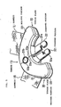
- a child restraint tongue 10 includes a pair of detachable left and right tongue plates 20 and 30.
- the tongue plates 20 and 30 are attached to left and right harnesses (left and right shoulder belts) 1L and 1R, respectively, for restraining the body of a child passenger seated in a child restraint system (not shown).
- the tongue plates 20 and 30 include magnets 21 and 31 for attracting and joining them together.
- the child restraint tongue 10 is mounted to a buckle unit 2 in such a manner that the left and right tongue plates 20 and 30 are inserted in parallel into the tongue insertion holes 3L and 3R of the buckle unit 2, respectively, and latched by a latch claw 4.
- the buckle unit 2 is connected to a crotch belt 5 which creeps between the child passenger's legs from the seat of the child restraint system toward the front of the body of the child passenger.
- Reference numeral 6 indicates a latch release button for releasing the latch of the tongue plates 20 and 30 by the latch claw 4.
- the buckle unit 2 of this embodiment is constructed such that unless the left and right tongue plates 20 and 30 are inserted into the tongue insertion holes 3L and 3R at the same time, respectively, the latch claw 4 does not latch the tongue plates 20 and 30.
- the tongue plates 20 and 30 include the magnets 21 and 31, inserted portions 22 and 32 which are inserted into the tongue insertion holes 3L and 3R of the buckle unit 2, and holding portions 23 and 33 provided at the base of the inserted portions 22 and 32 (the rear ends of the inserted portions 22 and 32 in the direction of insertion into the tongue insertion holes 3L and 3R), respectively.
- the holding portions 23 and 33 connect to the harnesses 1L and 1R, respectively.
- Reference numerals 22a and 32a indicate latch-claw engaging portions with which the latch claw 4 is brought into engagement when the inserted portions 22 and 32 are inserted into the tongue insertion holes 3L and 3R by a specified depth, respectively.
- the latch-claw engaging portions 22a and 32a are recesses which are formed by cutting off the right side of the left inserted portion 22 and the left side of the right inserted portion 32 which are opposed when the tongue plates 20 and 30 are arranged in parallel as shown in Fig. 2 .
- the right side of the left holding portion 23 and the left side of the right holding portion 33 which are opposed when the tongue plates 20 and 30 are arranged in parallel form linear guide surfaces 23a and 33a which attach closely to each other.
- the magnets 21 and 31 are embedded in the guide surfaces 23a and 33a, respectively.
- the magnets 21 and 31 are disposed such that the north pole and the south pole are opposed. Accordingly, when the left and right tongue plates 20 and 30 are disposed in parallel, the guide surfaces 23a and 33a are closely bonded together by the attracting force of the magnets 21 and 31 to join the left and right tongue plates 20 and 30 together.
- one guide surface 23a has a locating projection 23b projecting therefrom, while the other guide surface 33a has a recess 33b with which the projection 23b is brought into engagement when the guide surfaces 23a and 33a attach to each other.
- the guide surfaces 23a and 33a are opposed to each other, with the projection 23b brought into engagement with the recess 33b. Accordingly, the left and right tongue plates 20 and 30 are joined together without misalignment.
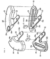
- the left and right tongue plates 20 and 30 include core materials 24 and 34 which function as the respective frameworks thereof, front covers 25F and 35F which cover the surface of the core materials 24 and 34, and back covers 25B and 35B which cover the back thereof, respectively.
- the core materials 24 and 34 are made of metal plates, while the front covers 25F and 35F and the back covers 25B and 35B are made of synthetic resin.
- the core materials 24 and 34 serve as framework for integrating the inserted portions 22 and 32 and the holding portions 23 and 33, respectively.
- Reference numerals 24a and 34a are harness insertion holes provided in the positions of the core materials 24 and 34 which serve as the framework of the holding portions 23 and 33, respectively.
- the harnesses 1L and 1R are passed through the harness insertion holes 24a and 34a, respectively.
- the front covers 25F and 35F are mounted on the surface of the core materials 24 and 34, while the back covers 25B and 35B are mounted on the back of the core materials 24 and 34, respectively.
- the respective outer rims of the front covers 25F and 35F and the back covers 25B and 35B are bonded together by joining means such as welding.
- Reference numerals 25b and 35b in Fig. 6 denote projections for fitting the front covers 25F and 35F and the back covers 25B and 35B together, respectively.
- the magnets 21 and 31 are disposed in the inner region between the front covers 25F and 35F and the back covers 25B and 35B such that they are located on the back of the guide surfaces 23a and 33a, respectively, when the front covers 25F and 35F and the back covers 25B and 35B are mounted to the core materials 24 and 34, respectively.
- Reference numerals 25a and 35a of Fig. 6 indicate magnet cases for accommodating the magnets 21 and 31, respectively.
- the core materials 24 and 34 and the magnets 21 and 31 may be covered with synthetic resin by insert molding.
- the guide surfaces 23a and 33a are opposed to each other, with the projection 23b on one guide surface 23a brought into engagement with the recess 33b of the other guide surface 33a and thus the left and right tongue plates 20 and 30 are joined together in parallel by the attracting force of the magnets 21 and 31. Then the inserted portions 22 and 32 of the tongue plates 20 and 30 are inserted into the tongue insertion holes 3L and 3R of the buckle unit 2, respectively.
- the latch release button 6 of the buckle unit 2 is operated.
- the latch of the tongue plates 20 and 30 with the latch claw 4 is released and as such, the inserted portions 22 and 32 are brought out of engagement with the tongue insertion holes 3L and 3R.
- the left and right tongue plates 20 and 30 of the child restraint tongue 10 are joined together by the attracting force of the magnets 21 and 31. Accordingly, to join them, the guide surfaces 23a and 33a have only to be brought into contact with each other, with the locating projection 23b fitted in the recess 33b, so that the joining operation is very easy. Also, after the tongue plates 20 and 30 have been joined together, the connection can be maintained by the attracting force of the magnets 21 and 31 without the need for retaining them to prevent the separation of them, thus facilitating insertion of the tongue plates 20 and 30 into the buckle unit 2.
Landscapes
- Engineering & Computer Science (AREA)
- Health & Medical Sciences (AREA)
- Child & Adolescent Psychology (AREA)
- General Health & Medical Sciences (AREA)
- Aviation & Aerospace Engineering (AREA)
- Transportation (AREA)
- Mechanical Engineering (AREA)
- Automotive Seat Belt Assembly (AREA)
- Buckles (AREA)
- Seats For Vehicles (AREA)
Claims (2)
- Kinderrückhaltezunge, die eingerichtet ist, am Gurtzeug von Kinderrückhaltesystemen befestigt zu werden, die in Autos eingebaut werden, wobei die Kinderrückhaltezunge (10) ein Paar Zungenplatten (20, 30), die parallel in Zungeneinsatzlöcher einer Schlosseinheit (2) eingesetzt werden sollen, und Magnete (21, 31) aufweist, um die Zungenplatten (20, 30) durch Anziehung miteinander zu verbinden,
wobei der Magnet (21, 31) in eine lineare Führungsfläche (23a, 33a) eingebettet ist, wobei die Führungsflächen in jeder der Zungenplatten (20, 30) vorgesehen sind und eng aneinander befestigt sind, wenn die Zungenplatten (20, 30) parallel angeordnet sind,
und
wobei wenn die Führungsflächen (23a, 33a) aneinander befestigt sind, ein Positionierungsvorsprung (23b), der von einer Führungsfläche (23a) vorsteht, mit einer Aussparung (33b) der anderen Führungsfläche (33) ein Eingriff steht. - Kinderrückhaltesystem, das die Kinderrückhaltezunge (10) nach Anspruch 1 und eine Schlosseinheit (2) aufweist, in die die Kinderrückhaltezunge (10) eingesetzt wird.
Applications Claiming Priority (2)
| Application Number | Priority Date | Filing Date | Title |
|---|---|---|---|
| JP2003421052A JP4604482B2 (ja) | 2003-12-18 | 2003-12-18 | チャイルドシート用トング及びチャイルドシート |
| JP2003421052 | 2003-12-18 |
Publications (2)
| Publication Number | Publication Date |
|---|---|
| EP1547484A1 EP1547484A1 (de) | 2005-06-29 |
| EP1547484B1 true EP1547484B1 (de) | 2016-11-30 |
Family
ID=34544907
Family Applications (1)
| Application Number | Title | Priority Date | Filing Date |
|---|---|---|---|
| EP04028577.7A Expired - Lifetime EP1547484B1 (de) | 2003-12-18 | 2004-12-02 | Steckzunge für ein Kinderrückhaltesystem und Kinderrückhaltesystem |
Country Status (3)
| Country | Link |
|---|---|
| EP (1) | EP1547484B1 (de) |
| JP (1) | JP4604482B2 (de) |
| CN (1) | CN1628567A (de) |
Families Citing this family (13)
| Publication number | Priority date | Publication date | Assignee | Title |
|---|---|---|---|---|
| CN101797087B (zh) * | 2009-02-06 | 2014-06-18 | 荷兰商伍轮实业股份有限公司 | 组合式扣具 |
| US8444222B2 (en) | 2009-04-07 | 2013-05-21 | Amsafe Commercial Products, Inc. | Child safety seat attachment belt retractor system |
| JP5347724B2 (ja) * | 2009-06-01 | 2013-11-20 | タカタ株式会社 | チャイルドシート |
| US8720019B2 (en) | 2009-11-10 | 2014-05-13 | Amsafe Commercial Products, Inc. | Buckle assemblies for personal restraint systems and associated methods of use and manufacture |
| CN104494478B (zh) * | 2014-12-23 | 2017-09-22 | 常州市博聪儿童用品股份有限公司 | 用于汽车儿童座椅的锁扣连接装置 |
| US9781977B2 (en) | 2015-08-11 | 2017-10-10 | Shield Restraint Systems, Inc. | Interlocking web connectors for occupant restraint systems and associated methods of use and manufacture |
| NL2016287B1 (en) * | 2016-02-19 | 2017-09-20 | Joolz Holding B V | Buckle. |
| US10357083B2 (en) | 2016-09-16 | 2019-07-23 | Shield Restraint Systems, Inc. | Buckle assemblies and associated systems and methods for use with child seats and other restraint systems |
| US11124152B2 (en) | 2018-11-20 | 2021-09-21 | Shield Restraint Systems, Inc. | Buckle assemblies for use with child seats and other personal restraint systems |
| KR102450616B1 (ko) * | 2019-06-06 | 2022-10-05 | 원더랜드 스위처랜드 아게 | 자기 버클 어셈블리 |
| CN117016926A (zh) | 2019-07-17 | 2023-11-10 | 明门瑞士股份有限公司 | 扣具 |
| KR102668104B1 (ko) * | 2022-08-05 | 2024-05-22 | 이재완 | 유아용 카시트에 적용하기 위한 시트벨트 착용감지장치 |
| KR102935017B1 (ko) * | 2023-12-13 | 2026-03-05 | 이재완 | 벨트 체결 감지 장치가 텅부에 형성되는 스마트 카시트용 시트 벨트 체결 장치 |
Family Cites Families (19)
| Publication number | Priority date | Publication date | Assignee | Title |
|---|---|---|---|---|
| GB875807A (en) * | 1957-02-09 | 1961-08-23 | Baermann Max | Improvements in or relating to permanent magnets |
| CH608351A5 (de) * | 1976-06-16 | 1979-01-15 | Stephan Marbacher | |
| JPH0225286Y2 (de) * | 1985-06-14 | 1990-07-12 | ||
| US5023981A (en) * | 1989-06-22 | 1991-06-18 | Indiana Mills & Manufacturing, Inc. | Belt buckle with interlocking dual tongue |
| US5142748A (en) * | 1989-06-22 | 1992-09-01 | Indiana Mills And Manufacturing, Inc. | Belt buckle with interlocking dual tongue and floating peg |
| US5220713A (en) * | 1992-08-28 | 1993-06-22 | Trw Vehicle Safety Systems Inc. | Apparatus for use with a safety belt |
| JPH0870912A (ja) * | 1994-09-06 | 1996-03-19 | Takata Kk | 幼児用拘束保護シートのバックル装置 |
| IT1297007B1 (it) * | 1997-12-22 | 1999-08-03 | Sama S P A | Chiusura magnetica ad innesto reciproco per borse, zaini, capi di abbigliamento e simili |
| US6505385B2 (en) * | 1997-12-22 | 2003-01-14 | Sama S.P.A. | Magnetic closure with mutual interlock for bags, knapsacks, items of clothing and the like |
| JP2001137013A (ja) * | 1999-11-10 | 2001-05-22 | Combi Corp | 左右同時ロック用バックル |
| JP2001278004A (ja) * | 2000-03-30 | 2001-10-10 | Combi Corp | チャイルドシートのシートベルト装置およびバックル |
| JP2001322529A (ja) * | 2000-05-12 | 2001-11-20 | Riiman Kk | チャイルドシートの安全ベルト |
| JP4008652B2 (ja) * | 2000-11-17 | 2007-11-14 | 芦森工業株式会社 | バックル装置 |
| JP2002191410A (ja) * | 2000-12-26 | 2002-07-09 | Yamato Shoji Nire:Kk | 止め具 |
| JP2002199907A (ja) * | 2000-12-31 | 2002-07-16 | Yamato Shoji Nire:Kk | 止め具 |
| JP2002199908A (ja) * | 2001-01-01 | 2002-07-16 | Yamato Shoji Nire:Kk | 止め具 |
| JP2002238619A (ja) * | 2001-02-15 | 2002-08-27 | Combi Corp | チャイルドシートのタングプレート同時係止装置 |
| JP3813468B2 (ja) * | 2001-06-11 | 2006-08-23 | 芦森工業株式会社 | バックル装置 |
| DE60123239T2 (de) * | 2001-09-21 | 2007-09-13 | Belt & Buckle S.R.L. | Gurtschnalle für Sicherheitsgurt mit drei Zungen, insbesondere für Kindersitze in Kraftfahrzeugen und dergleichen |
-
2003
- 2003-12-18 JP JP2003421052A patent/JP4604482B2/ja not_active Expired - Fee Related
-
2004
- 2004-12-02 EP EP04028577.7A patent/EP1547484B1/de not_active Expired - Lifetime
- 2004-12-17 CN CN200410082161.6A patent/CN1628567A/zh active Pending
Non-Patent Citations (1)
| Title |
|---|
| None * |
Also Published As
| Publication number | Publication date |
|---|---|
| JP2005178513A (ja) | 2005-07-07 |
| EP1547484A1 (de) | 2005-06-29 |
| CN1628567A (zh) | 2005-06-22 |
| JP4604482B2 (ja) | 2011-01-05 |
Similar Documents
| Publication | Publication Date | Title |
|---|---|---|
| EP1547484B1 (de) | Steckzunge für ein Kinderrückhaltesystem und Kinderrückhaltesystem | |
| US20120080917A1 (en) | Magnetic buckle assemblies and associated methods for use with child seats and other restraint systems | |
| EP0607664A1 (de) | Gurtschloss für ein Kinderrückhaltesystem | |
| EP0348075A1 (de) | Schnalle | |
| JP5514569B2 (ja) | バックルモジュール | |
| US7117568B2 (en) | Buckle assembly | |
| EP2392503B1 (de) | Kindertragegurt-Befestigungssystem | |
| KR100732730B1 (ko) | 자석식 스트랩 체결기구 | |
| EP3318155B1 (de) | Gurtzeugbefestigungssystem | |
| US11124096B2 (en) | Seat | |
| CN102006796A (zh) | 用于与儿童座椅和其它束缚系统一起使用的扣组件和相关联的连接器 | |
| EP2377718A1 (de) | Sitzgurtbefestiger für eine Kindertragvorrichtung | |
| CN114423311B (zh) | 具有两个能够与壳体模块连接的封闭部件的封闭装置 | |
| CN109803554A (zh) | 特别是用于袋子、背包等的磁性闭合件 | |
| GB2079833A (en) | Buckles for baby carriers | |
| US8196268B1 (en) | Fastening system | |
| AU2015341929A1 (en) | Sensing device, closure device comprising said sensing device and method for manufacturing said sensing device | |
| JP4380019B2 (ja) | ウェビング挿通部材 | |
| JP7211619B2 (ja) | シートベルト用バックル | |
| CN103057513B (zh) | 具有胸扣装置的儿童安全带 | |
| EP3752788B1 (de) | Schnelllösbares system für eine körperpanzerung | |
| US9241544B2 (en) | Seat-belt lock assembly | |
| CN105620329B (zh) | 座垫组装构造以及车辆用座椅 | |
| WO2022006624A1 (en) | A belt buckle | |
| DE69803324D1 (de) | Schnalle für einen Dreitrum-Sicherheitsgurt an Sicherheitssitzen für in Kraftfahrzeugen u.dgl. mitgeführte Kinder |
Legal Events
| Date | Code | Title | Description |
|---|---|---|---|
| PUAI | Public reference made under article 153(3) epc to a published international application that has entered the european phase |
Free format text: ORIGINAL CODE: 0009012 |
|
| AK | Designated contracting states |
Kind code of ref document: A1 Designated state(s): AT BE BG CH CY CZ DE DK EE ES FI FR GB GR HU IE IS IT LI LT LU MC NL PL PT RO SE SI SK TR |
|
| AX | Request for extension of the european patent |
Extension state: AL BA HR LV MK YU |
|
| 17P | Request for examination filed |
Effective date: 20051107 |
|
| AKX | Designation fees paid |
Designated state(s): DE FR GB SE |
|
| 17Q | First examination report despatched |
Effective date: 20070601 |
|
| GRAP | Despatch of communication of intention to grant a patent |
Free format text: ORIGINAL CODE: EPIDOSNIGR1 |
|
| INTG | Intention to grant announced |
Effective date: 20160701 |
|
| GRAS | Grant fee paid |
Free format text: ORIGINAL CODE: EPIDOSNIGR3 |
|
| GRAA | (expected) grant |
Free format text: ORIGINAL CODE: 0009210 |
|
| AK | Designated contracting states |
Kind code of ref document: B1 Designated state(s): DE FR GB SE |
|
| REG | Reference to a national code |
Ref country code: GB Ref legal event code: FG4D |
|
| REG | Reference to a national code |
Ref country code: DE Ref legal event code: R081 Ref document number: 602004050393 Country of ref document: DE Owner name: JOYSON SAFETY SYSTEMS JAPAN K.K., JP Free format text: FORMER OWNER: TAKATA CORP., TOKIO/TOKYO, JP |
|
| REG | Reference to a national code |
Ref country code: DE Ref legal event code: R096 Ref document number: 602004050393 Country of ref document: DE |
|
| PG25 | Lapsed in a contracting state [announced via postgrant information from national office to epo] |
Ref country code: SE Free format text: LAPSE BECAUSE OF FAILURE TO SUBMIT A TRANSLATION OF THE DESCRIPTION OR TO PAY THE FEE WITHIN THE PRESCRIBED TIME-LIMIT Effective date: 20161130 |
|
| REG | Reference to a national code |
Ref country code: DE Ref legal event code: R097 Ref document number: 602004050393 Country of ref document: DE |
|
| PLBE | No opposition filed within time limit |
Free format text: ORIGINAL CODE: 0009261 |
|
| STAA | Information on the status of an ep patent application or granted ep patent |
Free format text: STATUS: NO OPPOSITION FILED WITHIN TIME LIMIT |
|
| GBPC | Gb: european patent ceased through non-payment of renewal fee |
Effective date: 20170228 |
|
| REG | Reference to a national code |
Ref country code: FR Ref legal event code: ST Effective date: 20170929 |
|
| 26N | No opposition filed |
Effective date: 20170831 |
|
| PG25 | Lapsed in a contracting state [announced via postgrant information from national office to epo] |
Ref country code: FR Free format text: LAPSE BECAUSE OF NON-PAYMENT OF DUE FEES Effective date: 20170130 |
|
| PGFP | Annual fee paid to national office [announced via postgrant information from national office to epo] |
Ref country code: DE Payment date: 20171211 Year of fee payment: 14 |
|
| PG25 | Lapsed in a contracting state [announced via postgrant information from national office to epo] |
Ref country code: GB Free format text: LAPSE BECAUSE OF NON-PAYMENT OF DUE FEES Effective date: 20170228 |
|
| REG | Reference to a national code |
Ref country code: DE Ref legal event code: R082 Ref document number: 602004050393 Country of ref document: DE Representative=s name: VOSSIUS & PARTNER PATENTANWAELTE RECHTSANWAELT, DE Ref country code: DE Ref legal event code: R081 Ref document number: 602004050393 Country of ref document: DE Owner name: JOYSON SAFETY SYSTEMS JAPAN K.K., JP Free format text: FORMER OWNER: TAKATA CORPORATION, TOKYO, JP |
|
| REG | Reference to a national code |
Ref country code: DE Ref legal event code: R119 Ref document number: 602004050393 Country of ref document: DE |
|
| PG25 | Lapsed in a contracting state [announced via postgrant information from national office to epo] |
Ref country code: DE Free format text: LAPSE BECAUSE OF NON-PAYMENT OF DUE FEES Effective date: 20190702 |