EP1547166B1 - Module de sources de lumiere et procede de fabrication - Google Patents
Module de sources de lumiere et procede de fabrication Download PDFInfo
- Publication number
- EP1547166B1 EP1547166B1 EP03773459.7A EP03773459A EP1547166B1 EP 1547166 B1 EP1547166 B1 EP 1547166B1 EP 03773459 A EP03773459 A EP 03773459A EP 1547166 B1 EP1547166 B1 EP 1547166B1
- Authority
- EP
- European Patent Office
- Prior art keywords
- frame
- light source
- source module
- leds
- module according
- Prior art date
- Legal status (The legal status is an assumption and is not a legal conclusion. Google has not performed a legal analysis and makes no representation as to the accuracy of the status listed.)
- Expired - Lifetime
Links
Images

Classifications
-
- H10W90/00—
-
- H—ELECTRICITY
- H10—SEMICONDUCTOR DEVICES; ELECTRIC SOLID-STATE DEVICES NOT OTHERWISE PROVIDED FOR
- H10H—INORGANIC LIGHT-EMITTING SEMICONDUCTOR DEVICES HAVING POTENTIAL BARRIERS
- H10H20/00—Individual inorganic light-emitting semiconductor devices having potential barriers, e.g. light-emitting diodes [LED]
- H10H20/80—Constructional details
- H10H20/85—Packages
- H10H20/8506—Containers
-
- H—ELECTRICITY
- H10—SEMICONDUCTOR DEVICES; ELECTRIC SOLID-STATE DEVICES NOT OTHERWISE PROVIDED FOR
- H10H—INORGANIC LIGHT-EMITTING SEMICONDUCTOR DEVICES HAVING POTENTIAL BARRIERS
- H10H20/00—Individual inorganic light-emitting semiconductor devices having potential barriers, e.g. light-emitting diodes [LED]
- H10H20/80—Constructional details
- H10H20/85—Packages
- H10H20/855—Optical field-shaping means, e.g. lenses
- H10H20/856—Reflecting means
-
- H10W72/01515—
-
- H10W72/075—
-
- H10W72/5363—
Definitions
- Such a light source module is eg in the published patent application DE 100 51 159 A1 described.
- the publication JP 2001-085748 A describes a light-emitting component.
- the frame is connected by the potting compound completely with the metal support on which the LEDs are arranged over an insulating layer, surface.
- the metal carrier expands differently from the frame, since the frame is usually not made of metal and thus the two materials have different coefficients of expansion.
- the invention is therefore based on the object of disclosing a light source module which also withstands strongly changing temperature conditions.
- This object is achieved in that the LEDs are surrounded by a frame between the frame and LEDs potting compound is arranged and the frame has expansion joints.
- the expansion joints can be realized either over extremely thin locations in the frame, which can deform in an expansion or via slots that go completely through the frame.
- the frame is segmented into a plurality of frame parts by expansion joints.
- a frame part preferably has a maximum of four recesses in which LEDs can be arranged. This number of recesses per frame part guarantees in a production of the frame made of plastic and the metal support made of aluminum, even at high temperature fluctuations high reliability and functionality.
- HUD Head-Up Display
- the segmentation of the frame for the production of the light source module is preferably carried out at the end of the process chain, i. after incorporation in the potting compound. This can e.g. done by means of a sawing device.
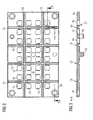
- FIG. 1 shows an LED light source module in partial sectional view.
- the light source module has two LEDs, one LED each having two optoelectronic components 1 arranged on a carrier substrate 2.
- the carrier substrate 2 is usually made of a good heat-conducting material and is arranged in each case via an intermediate insulating layer 3 and a carrier layer 5 on a metal support 4, which serves not only as a carrier, but also as a heat sink.
- the metal carrier 4 is preferably made of aluminum or copper to obtain a high heat dissipation.
- the insulating layer 3 integrated in the carrier substrate 2 generally consists of a silicon oxide layer 6 and a silicon nitride layer 7 applied to the silicon oxide layer 6.
- the silicon oxide layer is applied to a carrier layer 5 of silicon substrate.
- the insulating effect is achieved in particular by the silicon nitride and silicon oxide layers 7 and 6, wherein the silicon substrate 5 essentially serves only as a carrier material.
- On the insulating layer 7 are conductive metal pads 20 for contacting the LED.
- silicon layers can be applied extremely thinly and have a good thermal conductivity, these layers are ideal for electrical insulation and heat dissipation from the optoelectronic components 1 via the carrier substrates 2 to the metal carrier 4.
- a frame 10 is provided on the light source module mounted, which in each case encloses a carrier substrate 2 with mounted optoelectronic components 1.
- the frame 10 is glued to the underside with the circuit boards 8, so that the spaces in which the LEDs are located, can be poured out.
- the frame is first cast with reflective potting compound 11, such as white silicone or a filling compound with titanium oxide (TiO 2 ) or an epoxy resin mixed with titanium oxide particles.
- reflective potting compound 11 such as white silicone or a filling compound with titanium oxide (TiO 2 ) or an epoxy resin mixed with titanium oxide particles.
- the casting takes place until just below the upper edge of the carrier substrate 2, wherein the surface of the reflective potting compound 11 is concave to the inner edge of the frame 10.
- a potting of the interior is carried out with clear potting compound 12, for which purpose usually transparent silicone or transparent epoxy resin is used.
- the frame 10 is made for reasons of cost usually made of plastic, so that with strong temperature differences large loads respect.
- the LEDs result because the plastic frame 10 expands differently, as the usually made of aluminum metal support. 4
- expansion joints 13 are provided in the frame, over which the highly temperature-dependent expansion of the metal support 4 can be intercepted from aluminum.
- the expansion joints 13 may be formed as a strong tapered body in the frame 10, so that at this highly tapered body of the plastic Frame 10 can deform elastically under loads occurring.
- the expansion joints 13, as in FIG. 1 also be designed as a complete separation of the frame 10 at this point.
- a separating cut 14 proceed in the expansion joint 13, so that separate frame parts 10a and 10b arise.
- FIG. 2 shows in a view from above the complete frame 10, as used for example for a light source module for a head-up display system (HUD system) in a motor vehicle.
- HUD system head-up display system
- the frame 10 has slaughterunddreisig recesses 14, in each of which a carrier substrate 2 with at least two optoelectronic devices 1, as in FIG. 1 represented, are arranged.
- the light points are arranged in a grid of 4.5 mm in 8 columns and 4 rows.
- Polychromic light points are obtained by arranging a plurality of optoelectronic components 1 of different color on a carrier substrate 2.
- the expansion joints 13 are arranged in a grid shape in the frame 10, so that the frame is divided into several segments by the grid-shaped expansion joints 13 ,
- a frame segment in this case comprises a maximum of four recesses 14th
- FIG. 3 shows the section AA FIG. 1 by the frame 10.
- the frame 10 is formed substantially flat and has on its underside pin 15, with which it can be mounted on the metal support 4. Furthermore are also provided mounting holes 16, which can also be used for shipment to the metal support.
- the recesses 14 are shown in cross section, which have on the underside small undercuts 17, so that the reflective potting compound 11 is also received positively.
- the frame on both sides of a trapezoidal recess which can either be chosen so that even the thin web absorbs the deformation or, as in FIG. 1 represented, at this point by means of a sawing device, the remaining web is severed with a separating cut 14.
- the separation can be done after completion of mounting the frame on the metal support 4 and the casting of the recesses 14.
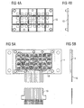
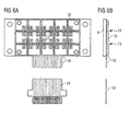
- FIGS. 4 to 6 schematically the assembly of the frame 10 is shown briefly.
- the FIGS. 4a to 6a each show the view from above, Figure 4b to 6b the side view.
- FIGS. 4a and 4b show the in the FIGS. 2 and 3 described framework
- FIGS. 5a and 5b show the metal support 4 with applied insulating and carrier layer and a flexible printed circuit board 18 arranged thereon with a flexible conductor connection 19, the carrier substrates 2 and the optoelectronic components 1 being applied to the flexible printed circuit board 18.
- FIGS. 6a and 6b show how the frame 10 is merely attached to the metal support 4 with the already applied flexible circuit board 18 and glued to it.
- the severing of the expansion joints 13 with the sawing device can already be done after this process step or only after the casting of the recesses 14.
Landscapes
- Led Device Packages (AREA)
Claims (8)
- Module de source de lumière présentant plusieurs LED raccordés de manière isolée à un support métallique (4),
les LED étant entourées par un cadre (10),
une pâte de coulée (11, 12) étant disposée entre le cadre (10) et les LED et le cadre (10) présentant des joints de dilatation (13). - Module de source de lumière selon la revendication 1, dans lequel le cadre (10) est segmenté en plusieurs parties (10a, 10b) de cadre par des joints de dilatation.
- Module de source de lumière selon l'une des revendications 1 ou 2, dans lequel pour chaque partie de cadre, au plus quatre découpes (14) sont prévues pour la reprise de LED.
- Module de source de lumière selon l'une des revendications 1 à 3, dans lequel le cadre (10) est réalisé en matière synthétique.
- Module de source de lumière selon l'une des revendications 1 à 4, dans lequel le cadre (10) est collé sur une carte de circuit (8) sur son côté inférieur.
- Module de source de lumière selon l'une des revendications 1 à 5, dans lequel le support métallique (4) est réalisé en aluminium ou en cuivre.
- Module de source de lumière selon l'une des revendications 1 à 6, dans lequel les LED sont disposés en trame.
- Procédé de fabrication d'un module de source de lumière selon l'une des revendications 2 à 7, dans lequel la segmentation du cadre (10) est réalisée avec un dispositif de sciage de telle sorte que des découpes de séparation (14) soient formées entre les parties de cadre.
Applications Claiming Priority (3)
| Application Number | Priority Date | Filing Date | Title |
|---|---|---|---|
| DE10245945A DE10245945A1 (de) | 2002-09-30 | 2002-09-30 | Lichtquellenmodul sowie Verfahren zu dessen Herstellung |
| DE10245945 | 2002-09-30 | ||
| PCT/DE2003/003189 WO2004032571A2 (fr) | 2002-09-30 | 2003-09-24 | Module de sources de lumiere et procede de fabrication |
Publications (2)
| Publication Number | Publication Date |
|---|---|
| EP1547166A2 EP1547166A2 (fr) | 2005-06-29 |
| EP1547166B1 true EP1547166B1 (fr) | 2015-03-04 |
Family
ID=31984359
Family Applications (1)
| Application Number | Title | Priority Date | Filing Date |
|---|---|---|---|
| EP03773459.7A Expired - Lifetime EP1547166B1 (fr) | 2002-09-30 | 2003-09-24 | Module de sources de lumiere et procede de fabrication |
Country Status (7)
| Country | Link |
|---|---|
| US (1) | US7456500B2 (fr) |
| EP (1) | EP1547166B1 (fr) |
| JP (1) | JP2006501657A (fr) |
| CN (1) | CN1735974B (fr) |
| DE (1) | DE10245945A1 (fr) |
| TW (1) | TWI233701B (fr) |
| WO (1) | WO2004032571A2 (fr) |
Families Citing this family (35)
| Publication number | Priority date | Publication date | Assignee | Title |
|---|---|---|---|---|
| JP2006066513A (ja) * | 2004-08-25 | 2006-03-09 | Rohm Co Ltd | 発光装置および表示装置 |
| JP2006120691A (ja) * | 2004-10-19 | 2006-05-11 | Matsushita Electric Ind Co Ltd | 線状光源装置 |
| JP2006210624A (ja) * | 2005-01-27 | 2006-08-10 | Toshiba Lighting & Technology Corp | 発光装置 |
| JP2006222358A (ja) * | 2005-02-14 | 2006-08-24 | Ngk Spark Plug Co Ltd | 発光素子実装用配線基板 |
| JP2007329394A (ja) * | 2006-06-09 | 2007-12-20 | Hitachi Lighting Ltd | 光源モジュール、光源モジュールの製造方法および液晶表示装置 |
| CN100499119C (zh) * | 2006-07-07 | 2009-06-10 | 启萌科技有限公司 | 发光二极管模组 |
| CN100485925C (zh) * | 2006-07-07 | 2009-05-06 | 启萌科技有限公司 | 发光二极管模组 |
| US7621752B2 (en) * | 2007-07-17 | 2009-11-24 | Visteon Global Technologies, Inc. | LED interconnection integrated connector holder package |
| US8125784B2 (en) * | 2008-08-13 | 2012-02-28 | Continental Automative Systems, Inc. | Seal apparatus and method of manufacturing the same |
| DE102008049188A1 (de) * | 2008-09-26 | 2010-04-01 | Osram Opto Semiconductors Gmbh | Optoelektronisches Modul mit einem Trägersubstrat und einer Mehrzahl von strahlungsemittierenden Halbleiterbauelementen und Verfahren zu dessen Herstellung |
| US9847268B2 (en) * | 2008-11-21 | 2017-12-19 | Advanpack Solutions Pte. Ltd. | Semiconductor package and manufacturing method thereof |
| EP2228841A1 (fr) * | 2009-03-09 | 2010-09-15 | Ledon Lighting Jennersdorf GmbH | Module DEL doté d'une production de lumière améliorée |
| US8350500B2 (en) * | 2009-10-06 | 2013-01-08 | Cree, Inc. | Solid state lighting devices including thermal management and related methods |
| US8264155B2 (en) * | 2009-10-06 | 2012-09-11 | Cree, Inc. | Solid state lighting devices providing visible alert signals in general illumination applications and related methods of operation |
| US8157412B2 (en) * | 2009-12-01 | 2012-04-17 | Shin Zu Shing Co., Ltd. | Light emitting diode substrate assembly |
| DE202010007032U1 (de) * | 2010-04-09 | 2011-08-09 | Tridonic Jennersdorf Gmbh | LED-Modul für Strahler |
| US20110254030A1 (en) * | 2010-04-15 | 2011-10-20 | Perkinelmer Elcos Gmbh | Liquid reflector |
| CN203260631U (zh) * | 2010-07-01 | 2013-10-30 | 西铁城控股株式会社 | Led光源装置 |
| US8322882B2 (en) * | 2010-09-22 | 2012-12-04 | Bridgelux, Inc. | Flexible distributed LED-based light source and method for making the same |
| US8652860B2 (en) | 2011-01-09 | 2014-02-18 | Bridgelux, Inc. | Packaging photon building blocks having only top side connections in a molded interconnect structure |
| US9461023B2 (en) | 2011-10-28 | 2016-10-04 | Bridgelux, Inc. | Jetting a highly reflective layer onto an LED assembly |
| DE102011105010A1 (de) * | 2011-06-20 | 2012-12-20 | Osram Opto Semiconductors Gmbh | Optoelektronisches Halbleiterbauelement und Verfahren zu dessen Herstellung |
| KR101278835B1 (ko) | 2011-06-28 | 2013-07-01 | 이형곤 | 엘이디용 회로기판원판, 회로기판, 엘이디유닛, 조명기구 및 제조방법 |
| TWI497668B (zh) * | 2011-07-27 | 2015-08-21 | 矽品精密工業股份有限公司 | 半導體封裝件及其製法 |
| DE102012217521A1 (de) * | 2012-09-27 | 2014-03-27 | Osram Opto Semiconductors Gmbh | Optoelektronisches Bauelement |
| JP6276557B2 (ja) * | 2013-10-25 | 2018-02-07 | シチズン電子株式会社 | Led発光装置 |
| US9859480B2 (en) * | 2015-08-20 | 2018-01-02 | Nichia Corporation | Light emitting device and method of manufacturing light emitting device |
| JP6611036B2 (ja) * | 2015-09-10 | 2019-11-27 | パナソニックIpマネジメント株式会社 | 発光装置及び照明用光源 |
| WO2017073680A1 (fr) * | 2015-10-29 | 2017-05-04 | 京セラ株式会社 | Substrat de montage d'élément électroluminescent et appareil d'émission de lumière |
| JP7197765B2 (ja) | 2018-08-03 | 2022-12-28 | 日亜化学工業株式会社 | 発光装置 |
| EP3780092B1 (fr) * | 2019-06-14 | 2023-03-01 | Shenzhen Goodix Technology Co., Ltd. | Structure de boîtier de puce et dispositif électronique |
| US20220057060A1 (en) * | 2020-08-21 | 2022-02-24 | Lumileds Llc | Multi-color lighting device |
| US12191285B2 (en) * | 2021-11-10 | 2025-01-07 | Infineon Technologies Ag | Optical projection device having a grid structure |
| DE102022205568A1 (de) | 2022-06-01 | 2023-12-07 | Continental Automotive Technologies GmbH | Anzeigevorrichtung und Fortbewegungsmittel |
| DE102022205566A1 (de) | 2022-06-01 | 2023-12-07 | Continental Automotive Technologies GmbH | Anzeigevorrichtung und Fortbewegungsmittel |
Family Cites Families (15)
| Publication number | Priority date | Publication date | Assignee | Title |
|---|---|---|---|---|
| US4845405A (en) | 1986-05-14 | 1989-07-04 | Sanyo Electric Co., Ltd. | Monolithic LED display |
| US4935665A (en) * | 1987-12-24 | 1990-06-19 | Mitsubishi Cable Industries Ltd. | Light emitting diode lamp |
| JPH0525604A (ja) | 1991-07-15 | 1993-02-02 | Nkk Corp | 溶融めつき設備における合金化制御装置 |
| JPH06140673A (ja) | 1992-10-23 | 1994-05-20 | Nippon Telegr & Teleph Corp <Ntt> | 光素子の実装法 |
| JPH06324857A (ja) | 1993-05-13 | 1994-11-25 | Toshiba Corp | コンピュータシステム |
| JP2901506B2 (ja) | 1994-10-24 | 1999-06-07 | スタンレー電気株式会社 | Ledドットマトリクス表示ユニット |
| SG46955A1 (en) * | 1995-10-28 | 1998-03-20 | Inst Of Microelectronics | Ic packaging lead frame for reducing chip stress and deformation |
| CH689339A5 (de) * | 1998-02-12 | 1999-02-26 | Staufert Gerhard | Konfektionierbares LED-Leuchpaneel. |
| US6133634A (en) * | 1998-08-05 | 2000-10-17 | Fairchild Semiconductor Corporation | High performance flip chip package |
| JP2001085748A (ja) | 1999-09-14 | 2001-03-30 | Matsushita Electric Works Ltd | 発光装置 |
| DE10051159C2 (de) | 2000-10-16 | 2002-09-19 | Osram Opto Semiconductors Gmbh | LED-Modul, z.B. Weißlichtquelle |
| JP3614776B2 (ja) * | 2000-12-19 | 2005-01-26 | シャープ株式会社 | チップ部品型ledとその製造方法 |
| TW473951B (en) * | 2001-01-17 | 2002-01-21 | Siliconware Precision Industries Co Ltd | Non-leaded quad flat image sensor package |
| US6547249B2 (en) * | 2001-03-29 | 2003-04-15 | Lumileds Lighting U.S., Llc | Monolithic series/parallel led arrays formed on highly resistive substrates |
| DE10229067B4 (de) | 2002-06-28 | 2007-08-16 | Osram Opto Semiconductors Gmbh | Optoelektronisches Bauelement und Verfahren zu dessen Herstellung |
-
2002
- 2002-09-30 DE DE10245945A patent/DE10245945A1/de not_active Ceased
-
2003
- 2003-09-24 EP EP03773459.7A patent/EP1547166B1/fr not_active Expired - Lifetime
- 2003-09-24 JP JP2004540508A patent/JP2006501657A/ja active Pending
- 2003-09-24 CN CN038233940A patent/CN1735974B/zh not_active Expired - Fee Related
- 2003-09-24 WO PCT/DE2003/003189 patent/WO2004032571A2/fr not_active Ceased
- 2003-09-24 US US10/529,718 patent/US7456500B2/en not_active Expired - Fee Related
- 2003-09-29 TW TW092126973A patent/TWI233701B/zh not_active IP Right Cessation
Also Published As
| Publication number | Publication date |
|---|---|
| US20060138441A1 (en) | 2006-06-29 |
| TW200411958A (en) | 2004-07-01 |
| WO2004032571A3 (fr) | 2005-04-21 |
| US7456500B2 (en) | 2008-11-25 |
| JP2006501657A (ja) | 2006-01-12 |
| TWI233701B (en) | 2005-06-01 |
| DE10245945A1 (de) | 2004-04-08 |
| WO2004032571A2 (fr) | 2004-04-15 |
| CN1735974A (zh) | 2006-02-15 |
| CN1735974B (zh) | 2010-05-05 |
| EP1547166A2 (fr) | 2005-06-29 |
Similar Documents
| Publication | Publication Date | Title |
|---|---|---|
| EP1547166B1 (fr) | Module de sources de lumiere et procede de fabrication | |
| EP1380056B2 (fr) | Ensemble composant optoelectronique et procede de fabrication d'un ensemble composant optoelectronique | |
| DE102011079708B4 (de) | Trägervorrichtung, elektrische vorrichtung mit einer trägervorrichtung und verfahren zur herstellung dieser | |
| EP2606510B1 (fr) | Procédé de fabrication d'au moins un composant semi-conducteur optoélectronique | |
| EP2601439B1 (fr) | Module d'éclairage optoélectronique et phare de véhicule | |
| DE102014116133B4 (de) | Optoelektronisches Bauelement, Verfahren zum Herstellen eines optoelektronischen Bauelements und Verfahren zum Herstellen einer optoelektronischen Anordnung | |
| DE102018121403A1 (de) | Verfahren zur Herstellung einer stabilisierten Platine | |
| WO2017032772A1 (fr) | Composant laser et procédé de réalisation | |
| DE102012212968A1 (de) | Optoelektronisches halbleiterbauteil mit elektrisch isolierendem element | |
| DE102014119390A1 (de) | Optoelektronisches Bauelement und Verfahren zu seiner Herstellung | |
| DE10245946C1 (de) | Verfahren zur Herstellung eines Lichtquellenmoduls | |
| DE102006001767B4 (de) | Halbleitermodul mit Halbleiterchips und Verfahren zur Herstellung desselben | |
| DE102014113844B4 (de) | Verfahren zum Herstellen eines optoelektronischen Bauelements und optoelektronisches Bauelement | |
| WO2019002098A1 (fr) | Composant à semi-conduteur optoélectronique et système comprenant un composant à semi-conduteur optoélectronique | |
| DE10124970B4 (de) | Elektronisches Bauteil mit einem Halbleiterchip auf einer Halbleiterchip-Anschlußplatte, Systemträger und Verfahren zu deren Herstellung | |
| DE102015112556B4 (de) | Videowand-Modul und Verfahren zu dessen Herstellung | |
| EP0243637B1 (fr) | Module de puissance à semi-conducteur | |
| DE102011083002A1 (de) | Elektrisches Steuergerät mit Moldgehäuse | |
| DE102005023947B4 (de) | Verfahren zur Herstellung eines optoelektronischen Halbleiterbauteils mit optisch transparenter Abdeckung | |
| WO2017194620A1 (fr) | Composant optoélectronique et procédé de fabrication d'un composant optoélectronique | |
| WO2024175773A1 (fr) | Composant électronique et procédé de montage d'un composant électronique | |
| DE102013218268A1 (de) | Träger und Leuchtvorrichtung | |
| DE10139985B4 (de) | Elektronisches Bauteil mit einem Halbleiterchip sowie Verfahren zu seiner Herstellung | |
| DE102018125506A1 (de) | Optoelektronische Vorrichtung und Verfahren zur Herstellung von optoelektronischen Vorrichtungen | |
| WO2022248247A1 (fr) | Composant semi-conducteur optoélectronique et panneau |
Legal Events
| Date | Code | Title | Description |
|---|---|---|---|
| PUAI | Public reference made under article 153(3) epc to a published international application that has entered the european phase |
Free format text: ORIGINAL CODE: 0009012 |
|
| 17P | Request for examination filed |
Effective date: 20050222 |
|
| AK | Designated contracting states |
Kind code of ref document: A2 Designated state(s): AT BE BG CH CY CZ DE DK EE ES FI FR GB GR HU IE IT LI LU MC NL PT RO SE SI SK TR |
|
| RBV | Designated contracting states (corrected) |
Designated state(s): DE |
|
| RIN1 | Information on inventor provided before grant (corrected) |
Inventor name: WAITL, GUENTER Inventor name: KROMOTIS, PATRICK |
|
| RAP1 | Party data changed (applicant data changed or rights of an application transferred) |
Owner name: OSRAM OPTO SEMICONDUCTORS GMBH |
|
| RAP1 | Party data changed (applicant data changed or rights of an application transferred) |
Owner name: OSRAM OPTO SEMICONDUCTORS GMBH |
|
| 17Q | First examination report despatched |
Effective date: 20090716 |
|
| GRAP | Despatch of communication of intention to grant a patent |
Free format text: ORIGINAL CODE: EPIDOSNIGR1 |
|
| INTG | Intention to grant announced |
Effective date: 20140925 |
|
| GRAS | Grant fee paid |
Free format text: ORIGINAL CODE: EPIDOSNIGR3 |
|
| GRAA | (expected) grant |
Free format text: ORIGINAL CODE: 0009210 |
|
| RIN1 | Information on inventor provided before grant (corrected) |
Inventor name: WAITL, GUENTER Inventor name: KROMOTIS, PATRICK |
|
| AK | Designated contracting states |
Kind code of ref document: B1 Designated state(s): DE |
|
| REG | Reference to a national code |
Ref country code: DE Ref legal event code: R096 Ref document number: 50315219 Country of ref document: DE Effective date: 20150416 |
|
| REG | Reference to a national code |
Ref country code: DE Ref legal event code: R097 Ref document number: 50315219 Country of ref document: DE |
|
| PLBE | No opposition filed within time limit |
Free format text: ORIGINAL CODE: 0009261 |
|
| STAA | Information on the status of an ep patent application or granted ep patent |
Free format text: STATUS: NO OPPOSITION FILED WITHIN TIME LIMIT |
|
| 26N | No opposition filed |
Effective date: 20151207 |
|
| PGFP | Annual fee paid to national office [announced via postgrant information from national office to epo] |
Ref country code: DE Payment date: 20180920 Year of fee payment: 16 |
|
| REG | Reference to a national code |
Ref country code: DE Ref legal event code: R119 Ref document number: 50315219 Country of ref document: DE |
|
| PG25 | Lapsed in a contracting state [announced via postgrant information from national office to epo] |
Ref country code: DE Free format text: LAPSE BECAUSE OF NON-PAYMENT OF DUE FEES Effective date: 20200401 |