EP1546472B1 - Strahlpumpe einsetzendes ausgrabungssystem und ausgrabungsverfahren. - Google Patents
Strahlpumpe einsetzendes ausgrabungssystem und ausgrabungsverfahren. Download PDFInfo
- Publication number
- EP1546472B1 EP1546472B1 EP03765678A EP03765678A EP1546472B1 EP 1546472 B1 EP1546472 B1 EP 1546472B1 EP 03765678 A EP03765678 A EP 03765678A EP 03765678 A EP03765678 A EP 03765678A EP 1546472 B1 EP1546472 B1 EP 1546472B1
- Authority
- EP
- European Patent Office
- Prior art keywords
- outlet
- suction
- bucket
- jet pump
- flow
- Prior art date
- Legal status (The legal status is an assumption and is not a legal conclusion. Google has not performed a legal analysis and makes no representation as to the accuracy of the status listed.)
- Expired - Lifetime
Links
- 238000000034 method Methods 0.000 title claims abstract description 15
- 238000009412 basement excavation Methods 0.000 title claims abstract description 10
- 239000000463 material Substances 0.000 claims abstract description 59
- 239000012530 fluid Substances 0.000 claims abstract description 37
- 238000004891 communication Methods 0.000 claims abstract description 17
- 239000011798 excavation material Substances 0.000 claims abstract description 7
- 230000009471 action Effects 0.000 claims abstract description 5
- 238000007873 sieving Methods 0.000 claims abstract description 5
- 238000004513 sizing Methods 0.000 claims abstract description 3
- 239000007788 liquid Substances 0.000 claims description 86
- XLYOFNOQVPJJNP-UHFFFAOYSA-N water Substances O XLYOFNOQVPJJNP-UHFFFAOYSA-N 0.000 claims description 31
- 239000011343 solid material Substances 0.000 claims description 11
- 239000007789 gas Substances 0.000 description 32
- 238000002347 injection Methods 0.000 description 27
- 239000007924 injection Substances 0.000 description 27
- 239000007787 solid Substances 0.000 description 20
- 230000000694 effects Effects 0.000 description 17
- 238000005086 pumping Methods 0.000 description 16
- 239000002002 slurry Substances 0.000 description 12
- 239000000203 mixture Substances 0.000 description 8
- -1 i.e. Substances 0.000 description 6
- 239000002245 particle Substances 0.000 description 6
- 239000013618 particulate matter Substances 0.000 description 4
- 239000004576 sand Substances 0.000 description 4
- XKRFYHLGVUSROY-UHFFFAOYSA-N Argon Chemical compound [Ar] XKRFYHLGVUSROY-UHFFFAOYSA-N 0.000 description 2
- IJGRMHOSHXDMSA-UHFFFAOYSA-N Atomic nitrogen Chemical compound N#N IJGRMHOSHXDMSA-UHFFFAOYSA-N 0.000 description 2
- 238000005299 abrasion Methods 0.000 description 2
- 238000013461 design Methods 0.000 description 2
- 239000011261 inert gas Substances 0.000 description 2
- 229910052500 inorganic mineral Inorganic materials 0.000 description 2
- 239000011344 liquid material Substances 0.000 description 2
- 229910052751 metal Inorganic materials 0.000 description 2
- 239000002184 metal Substances 0.000 description 2
- 150000002739 metals Chemical class 0.000 description 2
- 239000011707 mineral Substances 0.000 description 2
- 238000012360 testing method Methods 0.000 description 2
- 238000011144 upstream manufacturing Methods 0.000 description 2
- VYZAMTAEIAYCRO-UHFFFAOYSA-N Chromium Chemical compound [Cr] VYZAMTAEIAYCRO-UHFFFAOYSA-N 0.000 description 1
- 239000003082 abrasive agent Substances 0.000 description 1
- 230000002411 adverse Effects 0.000 description 1
- 238000013019 agitation Methods 0.000 description 1
- 229910052786 argon Inorganic materials 0.000 description 1
- QVGXLLKOCUKJST-UHFFFAOYSA-N atomic oxygen Chemical compound [O] QVGXLLKOCUKJST-UHFFFAOYSA-N 0.000 description 1
- 230000006835 compression Effects 0.000 description 1
- 238000007906 compression Methods 0.000 description 1
- 238000010276 construction Methods 0.000 description 1
- 238000007796 conventional method Methods 0.000 description 1
- 238000005260 corrosion Methods 0.000 description 1
- 230000007797 corrosion Effects 0.000 description 1
- 238000011161 development Methods 0.000 description 1
- 230000018109 developmental process Effects 0.000 description 1
- 238000006073 displacement reaction Methods 0.000 description 1
- 238000005265 energy consumption Methods 0.000 description 1
- 230000005484 gravity Effects 0.000 description 1
- 238000010348 incorporation Methods 0.000 description 1
- 238000004519 manufacturing process Methods 0.000 description 1
- 229910001092 metal group alloy Inorganic materials 0.000 description 1
- 238000005065 mining Methods 0.000 description 1
- 229910052757 nitrogen Inorganic materials 0.000 description 1
- 239000001301 oxygen Substances 0.000 description 1
- 229910052760 oxygen Inorganic materials 0.000 description 1
- 230000035515 penetration Effects 0.000 description 1
- 239000004033 plastic Substances 0.000 description 1
- 229920003023 plastic Polymers 0.000 description 1
- 230000008569 process Effects 0.000 description 1
- 230000008439 repair process Effects 0.000 description 1
- 238000005070 sampling Methods 0.000 description 1
- 238000000926 separation method Methods 0.000 description 1
- 239000007921 spray Substances 0.000 description 1
- 239000000126 substance Substances 0.000 description 1
- 230000000153 supplemental effect Effects 0.000 description 1
- 230000000007 visual effect Effects 0.000 description 1
Images


Classifications
-
- E—FIXED CONSTRUCTIONS
- E02—HYDRAULIC ENGINEERING; FOUNDATIONS; SOIL SHIFTING
- E02F—DREDGING; SOIL-SHIFTING
- E02F3/00—Dredgers; Soil-shifting machines
- E02F3/04—Dredgers; Soil-shifting machines mechanically-driven
- E02F3/88—Dredgers; Soil-shifting machines mechanically-driven with arrangements acting by a sucking or forcing effect, e.g. suction dredgers
- E02F3/8808—Stationary installations, e.g. installations using spuds or other stationary supports
-
- E—FIXED CONSTRUCTIONS
- E02—HYDRAULIC ENGINEERING; FOUNDATIONS; SOIL SHIFTING
- E02F—DREDGING; SOIL-SHIFTING
- E02F3/00—Dredgers; Soil-shifting machines
- E02F3/04—Dredgers; Soil-shifting machines mechanically-driven
- E02F3/28—Dredgers; Soil-shifting machines mechanically-driven with digging tools mounted on a dipper- or bucket-arm, i.e. there is either one arm or a pair of arms, e.g. dippers, buckets
- E02F3/36—Component parts
- E02F3/40—Dippers; Buckets ; Grab devices, e.g. manufacturing processes for buckets, form, geometry or material of buckets
-
- E—FIXED CONSTRUCTIONS
- E02—HYDRAULIC ENGINEERING; FOUNDATIONS; SOIL SHIFTING
- E02F—DREDGING; SOIL-SHIFTING
- E02F3/00—Dredgers; Soil-shifting machines
- E02F3/04—Dredgers; Soil-shifting machines mechanically-driven
- E02F3/88—Dredgers; Soil-shifting machines mechanically-driven with arrangements acting by a sucking or forcing effect, e.g. suction dredgers
- E02F3/90—Component parts, e.g. arrangement or adaptation of pumps
- E02F3/92—Digging elements, e.g. suction heads
- E02F3/9212—Mechanical digging means, e.g. suction wheels, i.e. wheel with a suction inlet attached behind the wheel
Definitions
- Another dredging technique involves the use of air to induce an upward flow of water. This technique has typically involved compressed air or gas, requiring expensive compression equipment. In addition, the combination of gas, water and solids has contributed to process instability in the mixing chamber of the device, as discussed in U.S. Patent No. 4,681,372 .
- U.S. Patent No. 5,811,013 Other jet eduction systems have used atmospheric air for the purpose of creating air bubbles for separation processes, as in U.S. Patent No. 5,811,013 . These systems are not designed to increase pump efficiency, prevent pump cavitation or increase pump flow as disclosed by the present invention.
- U.S. Patent 5,993,167 does disclose a jet eduction system which permits air to form a layer surrounding a high pressure flow of liquid, which is directed through a space and into a tube, thereby forming a vacuum in the space. Yet, this system does not produce vacuum sufficient for many commercial operations, and do es not provide for control of the weight percentage of solids in pumped slurries.
- JP 56159437 A discloses a hydraulic shovel which is operated to enfold a bucket.
- a high pressure water injection pump and an air compressor are driven and excavate and dredge actuating a water injection pressure air mixing pump in the bucket.
- a high pressure water from a shooting nozzle is shot toward a suction tube simultaneously with a pressure air from a shooting tube port via an inlet, earth and other matters excavated in the bucket are sucked by a strong force being generated and sent to a accumulator installed ashore through a fluidic feed tube.
- German application DE 197 15 284 A1 discloses deep sea mineral collector apparatus comprising a remote controlled unmanned vehicle positioned on the sea ground in the form of a excavator.
- US 2,952,083 discloses in a dredge construction, a bucket having digging means on a lower wall, a stick serving to mount the bucket, a carrier, pivoted means on the carrier for supporting the stick, a pump mounted upon the carrier for supporting the stick, a pump mounted upon the stick, means mounted on the stick for driving the pump, a suction head disposed within the space enclosed by the bucket, said head comprising a vertically extending hollow member having perforations of a size suitable for passing desired material , said head being journalled for turning within said bucket, means for cyclically turning the head to prevent clogging of the perforations with dredged material, nozzle means for delivering water jets into the bucket and in the direction towards the suction head from the open front of the bucket, and additional nozzle means carried by the bucket, and additional nozzle means carried by the bucket an disposed to deliver jets of water into the
- a need continues to exist for a commercially viable jet eduction system which moves large volumes of matter with very little wear and tear on the system.
- a need also exists for systems which enabling users to achieve greater pumping efficiency.
- excavation systems employing vacuum pumps to enable handling of heavy or agglomerated material which is not readily suctioned without agitation.
- the present invention overcomes the shortcoming of prior developments by the subject matter of claim 1, providing, among other things, a pumping system which can (a) increase the quantity of material moved, relative to previously developed pumps, without an increase in energy consumption, (b) move solid materials with minimal wear on component parts, (c) overcome the problems associated with traditional venturi effect pumps, (d) include specific component parts which are designed to wear and which can be easily changed, (e) produce a vacuum for suctioning material with little or no cavitation, and/or (f) enable the control of the solid to liquid ratio of the material being pumped to drastically increase the pumping efficiency.
- the present invention provides an efficient mixing system which employs a jet pump of this invention and enables users to rapidly form a liquid and solid material mixture, preferably one in which the mixture is substantially homogeneous, to control the weight percent of solids in the resulting mixture, and to efficiently transport the mixture downstream from the jet pump to a desired location.
- an improved liquid jet pump is provided.
- the liquid jet pump is comprised of a nozzle assembly that pulls in atmospheric air.
- the liquid jet created by passage of liquid through the nozzle assembly has minimal deflection as it exits because of an atmospheric air bearing surrounding the liquid jet. Consequently, the liquid jet pump has improved efficiency and capacity.
- the liquid jet pump is configured to define a suction chamber and further comprises a suction pipe.
- the suction pipe pulls in the material to be pumped as the liquid jet from the nozzle assembly passes through the suction chamber.
- the liquid jet pump further comprises a target tube that receives the liquid jet combined with material to be pumped which enters the suction chamber after traveling through the suction pipe.
- the target tube is comprised of a housing support detachable from the suction chamber and a wear plate of abrasion-resistant material.
- this invention provides apparatus which is comprised of (a) a nozzle assembly which is sized and configured to (i) receive a pressurized liquid and a gas, and (ii) eject the pressurized liquid as a liquid flow while feeding the gas into proximity with the periphery of the liquid flow; (b) a housing defining a suction chamber into which the nozzle assembly may eject the liquid flow, the housing also defining a suction inlet and a suction outlet; (c) an outlet pipe extending from the suction outlet away from the suction chamber housing, said outlet pipe being configured for liquid communication with the suction chamber and being disposed to receive the liquid flow; the outlet pipe defining at least a first inner diameter along a portion of its length and a second inner diameter along another portion of its length, the second inner diameter being less than the first inner diameter; and (d) a suction pipe, a first end of the suction pipe opening into the suction chamber at the suction inlet, and a second end of the suction pipe opening into
- This invention also provides a system for dredging matter from the bottom of a body of water, the system comprising: (a) a pumping system as described above in this paragraph, (b) a buoyant platform equipped to raise and lower at least a portion of the pumping system relative to the bottom of the body of water, and (c) a first pump for providing the pressurized liquid to the nozzle assembly.
- a method of moving, from one location to another, a slurry comprised of a solid and a liquid comprises:
- This invention provides an excavation system comprising: (1) a bucket which defines an outlet at its base,(2) a suction tube in fluid communication with a jet pump and with the bucket outlet; and (3) a guard substantially covering the bucket outlet, wherein the jet pump is comprised of a nozzle assembly which is sized and configured to (i) receive a pressurized liquid and a gas, and (ii) eject the pressurized liquid as a liquid flow while feeding the gas into proximity with the periphery of the liquid-flow, so that when the jet pump creates a vacuum in the suction tube, material in the bucket which can pass though the guard is suctioned through the outlet.
- the jet pump further comprises a housing defining a suction chamber into which the nozzle assembly may eject the liquid flow, the housing further defining a suction inlet and a suction outlet ; and an outlet pipe extending from the suction outlet away from the suction chamber, the outlet pipe being configured for fluid communication with the suction chamber and being disposed to receive the liquid flow; the outlet pipe defining at least a first inner diameter along a portion of its length and a second inner diameter along another portion of its length, the second inner diameter being less than the first inner diameter.
- the bucket is pivotally attached to the end of an excavator arm or alternatively comprises a hopper.
- a method of excavating material comprises: (1) loading excavation material into a bucket which defines an outlet at its base, (2) sizing the excavation material by sieving action of a guard substantially covering the bucket outlet, (3) suctioning the sized material though the bucket outlet using a vacuum created by (a) injecting a pressurized liquid into a nozzle assembly of a jet pump in fluid communication with the bucket outlet to produce a flow of pressurized liquid, (b) providing a gas to the nozzle assembly to surround the flow of pressurized liquid with the gas, (c) directing the flow of pressurized liquid surrounded by the gas into a suction chamber of the jet pump in fluid communication with a suction pipe and an outlet pipe of the jet pump, the outlet pipe defining a venturi-like inner surface, and (d) directing the flow of pressurized liquid surrounded by the gas toward the outlet pipe to produce a vacuum at the end of the suction pipe which suction pipe defines a passageway in fluid communication with the outlet of the bucket
- Figure 1 is a plan view of one preferred dredging assembly embodiment of this invention.
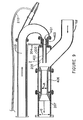
- Figure 2 is a sectional view of the jet pump component of the assembly of Fig. 1.
- Figure 3 is a sectional view of the jet pump components indicated on Fig. 2.
- Figure 4A is a sectional view of a preferred embodiment of the nozzle assembly showing minimal deflection of the liquid jet.
- Figure 4B is a sectional view of an embodiment of the nozzle assembly showing deflection of the liquid jet.
- Figure 5 is a perspective view of material moving through the nozzle assembly and suction chamber.
- Figure 6 is a perspective view of a preferred embodiment of the nozzle assembly, suction chamber and target tube of the invention.
- Figure 7 and Figure 8 are sectional views of a preferred embodiment of the nozzle assembly of the invention.
- Fig. 9 is a sectional view of another jet pump component of this invention which is an alternative to that illustrated in Fig. 2.
- Figs. 10 and 11 are sectional views the nozzle assembly from the jet pump component of Fig. 9.
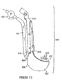
- Fig. 12 is a plan view of one preferred excavation system embodiment of this invention
- Fig. 13 is a plan view of an embodiment of the excavation system showing the bucket attached to an arm of an excavator.
- the gas employed in the pumping systems and methods of this invention will preferably be under no more than atmospheric pressure, to reduce risk of operations and cost.
- the gas preferably will be an inert gas, e.g., nitrogen or argon, when the liquid or other material being pumped could be volatile in the presence of certain atmospheric gases, e.g., oxygen. When such volatility is not an issue, the gas employed will be most conveniently atmospheric air.
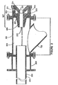
- Fig. 1 illustrates one preferred embodiment of this invention, in use on a barge 100 for dredging solid materials from a water source, such as a lake or river.
- Barge 100 is equipped with a cantilever system 101 to raise and lower a suction pipe 102 into the water source.
- Suction pipe 102 is connected to a jet pump 107 configured in accordance with this invention and further described hereinafter.
- a discharge (or "inlet") pipe 103 feeds water or other liquid pumped by a pump 104 to jet pump 107.
- Pump 104 is typically a centrifugal pump, but can be any kind of pumping means, such as a positive displacement pump or even another jet pump. Pump 104 can be contained in a pump housing 105.
- Discharge pipe 103 also feeds water or other liquid to a supplemental j et nozzle assembly, illustrated here as a j et nozzle 106, upstream from jet pump 107 and suction pipe 102.
- Jet nozzle 106 is sized and configured to project a pressurized liquid flow into the surrounding environment, to thereby break up solid material to facilitate its incorporation into the material pumped by jet pump 107.
- suction pipe 102 is shown in Figure 1 as an angled inlet to jet pump 107 before becoming parallel to discharge pipe 103, suction pipe 102 can be any angle greater than 0° and less than 180° to discharge pipe 103 for all or any part of the length of suction pipe 102.
- a dredge pump 108 can optionally be placed downstream of j et pump 107.
- Pump 108 is typically a centrifugal pump but can be any pumping means, as noted earlier for pump 104.
- Jet pump 107 for instance, can vary in size, from handheld unit to mounted on a bulldozer, mudbuggy or other vehicle, for use in various applications.
- the distance between pump 104 and jet pump 107, i.e., the length of the discharge pipe, can also vary greatly.
- Jet pump 107 includes nozzle assembly 307 (Figure 3 only), which in turn is comprised of a fluid nozzle 201, an air injection nozzle 202 and a nozzle housing 203.
- Nozzle housing 203 is a flanged member which is attached to and maintains the proper position of fluid nozzle 201 adjacent to air injection nozzle 202.
- Air intake 211 is one or more passages through nozzle housing 203. In the embodiment depicted, a single air intake 211 is shown although those skilled in the art could use more.
- a gas conduit in the form of an air hose 204 provides a gas to jet pump 107 and allows jet pump 107 to use air even when below the water level.
- Water or other fluid supplied by a pumping means passes through discharge (or "inlet") pipe 103, fluid nozzle 201, and air injection nozzle 202 into a housing 200 which defines a suction chamber 205.
- discharge (or "inlet") pipe 103 the fluid in the form of a liquid flow combines with material entering chamber 205 from suction pipe 102 via a suction inlet 109, and the combined stream enters a target tube 206 disposed within an outlet pipe 207 through a suction outlet 110 of chamber 205.
- the combined stream then passes through target tube 206 into outlet pipe 207.
- jet nozzle 106 extends from discharge (or "inlet") pipe 103, allowing a portion of the forced fluid supplied by pumping means to pass through jet nozzle 106.
- j et nozzle 106 contains a venturi 208 at its end opposite the end connected to discharge pipe 103. Venturi 208 is equipped with air hose 210 to allow entry of atmospheric air at aperture 209 when jet pump 107 is submerged.
- Jet nozzle 106 extends approximately the same length as suction pipe 102 and, as depicted in Figure 1, terminates approximately 0.30 meters (one (1) foot) from the open end of suction pipe 102. Fluid forced through jet nozzle 106 exits venturi 208 with air into the material that will be suctioned. An air bearing effect minimizes deflection and allows deeper penetration to loosen to the material being transferred. The jet stream also creates a churning effect that directs the churned material into the open end of suction pipe 102.
- jet nozzle 106 is shown in Figures 1 and 2 as a single attachment, in an alternate embodiment, multiples of jet nozzle 106 can be attached to discharge pipe 103. In another embodiment, one or more jet nozzles 106 can be attached to suction pipe 102, handheld, or mounted on other equipment, depending on the application.
- fluid nozzle 201 in the interior of nozzle housing 203, includes constricted throat 301. Fluid nozzle 201 is attached by a connecting means to air injection nozzle 202. Air gap 302 exists between constricted throat 301 and air injection nozzle 202. In one embodiment, air gap 302 between constricted throat 301 and air injection nozzle 202 at its narrowest point measures 0.48 of a cm (3/16 of an inch). The overall area and dimension at the narrowest point of air gap 302 will vary with the application and the material being transferred to optimize the suction effect.
- Fluid nozzle 201 is attached to air injection nozzle 202 by means of nozzle housing 203.
- Nozzle housing 203 is a flanged pipe with air intake 211 drilled into the pipe circumference. Although nozzle housing 203 is depicted with one air intake 211, those skilled in the art would know that multiple air intakes can be provided.
- Air injection nozzle 202 is provided with one or more air holes 304.
- air injection nozzle 202 has eight 1.27 cm (1 ⁇ 2 inch) holes 304 equal distance around the circumference of air injection nozzle 202.
- air injection nozzle 202 and fluid nozzle 201 When air injection nozzle 202 and fluid nozzle 201 are assembled, one of air holes 304 can align with air intake 211. Alignment however is not necessary, as air injection nozzle 202 further defines an annular trough 602 in its outer surface into which air holes 304 open, thereby providing a path for air flow around the circumference of nozzle 202 and into each of holes 304.
- Air hole 304 and air intake 211 allow the entry of atmospheric air to fill air gap 302.
- the forced delivery of liquid through constricted throat 301 creates a vacuum in air gap 302 that pulls in atmospheric air. Varying the amount of air entering air hole 304 creates an increased suction effect in air gap 302.
- vacuum in air gap 302 measured 73.66 cm (29 inches) Hg when air intake 211 was 10% open, compared to 25.4 cm (10 inches) Hg when air intake 211 was 100% open. Restriction of air though air intake 211 can be accomplished by any mechanical valve means, e.g., such as that depicted as valve 212 .
- a gas e.g., air
- the air surrounds the flow of fluid leaving constricted throat 301 and the combined fluid jet with surrounding air passes through air injection nozzle 202 .
- the fluid jet with the air exits air injection nozzle 202, passes through suction chamber 205, and enters target tube 206.
- the combined air fluid j et passes through suction chamber 205 with minimal deflection before entering target tube 206.
- FIG. 3 shows a visual correlation between the deflection of a liquid jet entering target tube 206, and the presence of atmospheric air in air gap 302.
- Figure 4A shows the liquid pattern with atmospheric air creating air bearing 501.
- Figure 4B depicts the liquid pattern exiting air injection nozzle 202 without atmospheric air present.
- the best results for pumping only water were achieved when the pump discharge pressure was 1034.21-1206.58 kPa (150-175 p.s.i.) and the vacuum in air gap 302 was 45.72-55.88 cm (18-22 inches) of Hg.
- Air bearing 501 around the liquid jet minimizes deflection, and thus, cavitation in suction chamber 205. Less cavitation reduces wear and the need to replace component parts, and increases flow through suction chamber 205 into target tube 206 with the liquid jet stream.
- suction chamber 205 is shown with suction pipe 102 entering at a 45° angle.
- the design of suction chamber 205 allows one to adjust the placement of air injection nozzle 202 so that air injection nozzle 202 is out of the flow of solid material entering suction chamber 205, so as to prevent wear, or further into suction chamber 205 so as to create a greater vacuum.
- Suction pipe 102 entering at an angle avoids the problem common to many eductor nozzles suffering excessive wear and corrosion by being placed in the flow of solid material.
- this configuration is a preferred embodiment to maximize the entry of slurry material with minimal abrasive effect, those skilled in the art would know that alternate angles greater than 0° and less than 180° can be utilized.
- suction chamber 205 measures 62.87 cm (243 ⁇ 4 inches) at A.
- the distance between nozzle opening 303 and one end of target tube 206 is 34.93 cm (133 ⁇ 4 inches) at B.
- Table 1 illustrates the ratio of total material exiting target tube 206 to pumped liquid entering fluid nozzle 201: Table 1 Pump Discharge Pressure in kPa (psia) Vacuum Measured In Air Gap in cm Hg (inches Hg) Liquid Exit Power in liters per min. (gallons per minute) Liquid Inlet Fluid Nozzle in liters per min.
- vacuum in air gap 302 measured 73.66 cm (29 inches) Hg when suctioning water, 60.96 cm (24 inches) Hg when suctioning slurry material containing sand, and 45.72 cm (18 inches) Hg when suctioning material containing gravel.
- target tube 206 allows the movement of larger quantities of material without any concurrent increase in horsepower to operate pump 104 providing the liquid flow. For example, testing has demonstrated movement of material containing 60-65% by weight of sand, as compared to the 18-20% of solids using conventional methods such as centrifugal pumps at the same flow rate or discharge pressure.
- Target tube 206 constitutes a segment of the outlet pipe in the form of a detachable wear plate in the preferred embodiment illustrated.
- the outlet pipe segment defines an inner surface, at least a portion of which in turn defines the second inner diameter of the outlet pipe.
- the target tube can be detached from outlet pipe 207 and suction chamber 205. The majority of wear from abrasive material occurs in target tube 206, not suction chamber 205, because of reduced cavitation from the air bearing effect on the liquid jet and the design of suction chamber 205.
- target tube 206 is fixably attached to target tube housing 306. Once target tube 206 is worn, target tube 206 can be removed by detaching target tube housing 306 from suction chamber 205 on one end and outlet pipe 207 on the other end without having to open suction chamber 205 .
- target tube 206 may be fixably attached at one end to a connecting means such as a split locking flange.
- the split locking flange could then hold target tube 206 in place at one end by connecting between outlet pipe 207 or suction chamber 205 and target tube housing 306.
- the opposite end of target tube 206 could then rest on target tube housing 306 using notches or other means to prevent axial or radial movement.
- a centrifugal dredge pump 108 as shown in Figure 1, can be placed downstream of target tube 206 despite the introduction of atmospheric air before nozzle opening 303. No cavitation occurs in centrifugal dredge pump 108 from the atmospheric air. This is counter to conventional wisdom regarding operation of centrifugal pumps by those skilled in the art.
- the atmospheric air likely dissolves in the liquid jet in or past target tube 206, further supporting the optimum effect observed when atmospheric air is restricted in its entry through air intake 211.
- Target tube 206 can vary in both length and diameter. Diameter will most often be determined by the particle size of the material conveyed. Length and diameter of target tube 206 will effect the distance and head pressure that jet pump 107 can generate.
- target tube 206 measures 91.44 cm (36 inches) in length, with 16.83 cm (6 5 ⁇ 8 inches) outer diameter and 15.24 cm (6 inches) inner diameter.
- Target tube housing 306 is composed of two 15.24 x 30.48 cm (6 x 12 inch) reducing flanges, each connected to one end of 32.39 cm (123 ⁇ 4 inch) pipe 25.4 cm (10 inches) long.
- Interior target tube wear plate 305 (as shown in Figure 3) is composed of abrasion-resistant material such as, e.g., metals with high chrome content.
- target tube 206 is a straight pipe with blunt edges.
- target tube 206 could have angled edges of a larger diameter than the diameter of the target tube body at one or both ends of target tube 206.
- the nozzle elements of Figure 7 are constructed according to specific proportions. Although the nozzle elements are shown as three separate elements, those skilled in the art would know that the nozzle assembly could be constructed of one or more elements of varying dimensions.
- Fluid nozzle 201 is 12.7 cm (5 inches) in length and 20.32 cm (8 inches) in outer diameter. Constricted throat 301 of fluid nozzle 201 at inner edge 701 narrows radially inward from 20.32 cm (8 inches) to 5.08 cm (2 inches) diameter at its narrowest point at a 45°angle. Fluid nozzle 201 measures 7.62 cm (3 inches) in diameter on outer edge 702.
- Air injection nozzle 202 is 32.70 cm (12 7 ⁇ 8 inches) in length. At one end, air injection nozzle 202 is 25.4 cm (10 inches) in diameter on outside surface 703, and 20.35 cm (8.01 inches) in diameter on inside surface 704. Outside surface 703 remains 25.4 cm (10 inches) in diameter axially for a length of 12.7 cm (5 inches), then drops radially to a diameter of 17.78 cm (7 inches), and angles inward radially to a diameter of 10.16 cm (4 inches) for the remaining length. In a preferred embodiment, air injection nozzle 202 has an angle of 102° between the smallest diameter at angled end in the vertical plane and angled edge.
- Air hole 304 is 1.27 cm (1 ⁇ 2 inch) in diameter equally spaced along the circumference of outside surface 703 located 5.08 cm (2 inches) from the end of air injection nozzle 202 that has a 25.4 cm (10 inch) diameter.
- nozzle housing 203 measures 34.29 cm (131 ⁇ 2 inches) at flanged end 705 connected to fluid nozzle 201.
- the outer diameter measures 48.26 cm (19 inches).
- Flanged end 705 has an inner diameter measuring 17.94 cm (7.0625 inches), sufficient to allow passage of air injection nozzle 202 at its angled end.
- Flanged end 705 has an inner diameter for the remaining length of 25.43 cm (10.01 inches) to accommodate air injection nozzle 202 at its largest point.
- Nozzle housing 203 has a 2.54 cm (1 inch) NPT connection in air intake 211.
- Figures 9, 10 and 11 illustrate another preferred embodiment of the present invention.
- This embodiment differs from the others illustrated in the previous figures in the configuration of the nozzle assembly and outlet pipe segment.
- the nozzle assembly of this particular embodiment is comprised of a fluid nozzle 401, an air pattern ring 402A, an air injection nozzle 402, and a nozzle housing 403.
- ring 402A can be replaced with modified rings when different air patterns are desired.
- Nozzle 402 is extended in length to permit the nozzle opening to be more proximate to target tube 406 (Fig. 9) without being so close to tube 406 so as to block larger particle size solids from passing from chamber 205 into tube 406.
- nozzle 402 may extend into the imaginary line of flow of suction pipe 102, represented on Fig. 9 with broken line Z, without suffering undue wear and tear as a result of solid material flowing into chamber 205.
- increased vacuum may be achieved through nozzle extension without substantial adverse wear upon nozzle 402.
- outlet pipe is comprised of a target tube (labeled 406 in Fig. 9) which defines a first inner diameter Q, the outlet pipe also defining a second inner diameter R which is less than inner diameter Q.
- target tube labeled 406 in Fig. 9
- outlet pipes of this invention may also be fabricated without a target tube but with a non-uniform inner surface so as to define a narrowing passage, so as to provide a venturi-like effect to the material exiting the suction chamber.
- a pump incorporating the features of that illustrated in Figs. 9-11 and having the following dimensions was employed to pump gravel, dirt and water from a gravel pit, and samples were taken to measure the percentage of solids which were pumped at various pressure settings.
- Table 2 Sample Jet Pump Vacuum at nozzle air intake cm Hg (inches Hg) Dredge Pump Vacuum downstream from Jet Pump cm Hg (inches Hg) Dredge Pump Discharge Pressure kPa (psia) Percent of Solids (wt%) Line Velocity from Dredge Pump meter per second (feet per second) Tons per Hour Jet Pressure upstream of nozzle assembly kPa (psia) 1 50.8 (20) 33.02 (13) 482.63 (70) 45 4.27 (14) 535 723.95 (105) 2 53.34 (21) 15.24 (6) 510.21 (74) 51 4.27 (14) 605 723.95 (105) 3 63.5 (25) 48.26 (19) 217.11 (75), 52 4.27 (14) 615 723.95 (105) 4 66.04 (26) 2.54 (1) 579.16 (84) 55 4.27 (14) 670 723.95 (105) 5 68.58 (27) 45.72 (18) 530.90 (77) 51 4.
- an efficient mixing system and method are provided by this invention, whereby the jet pump described herein is employed to mix a liquid with solid or slurry material to form a mixture, wherein the weight percent of solids in the mixture is controlled by controlling the air intake vacuum and the dredge pump intake pressure/vacuum as described above.
- Such mixing systems facilitate mixing volatile materials by simply using an inert gas for the gas intake at the nozzle assembly. Mixtures made in accordance with this system are particularly uniform and can be substantially homogenous, presumably on account of the forces applied to the liquid and solid material in, for example, the suction chamber of jet pumps of this invention.
- the present invention can be used in any application requiring significant suction effect of solid material in a liquid or gaseous environment.
- the invention can also be used for suction in gaseous or liquid environments without solids present, and maintain a significant suction effect.
- the invention can also be used in closed loop de-watering applications to remove excess water or moisture from material.
- the dimensions of the various component parts of devices of this invention may vary depending upon the circumstances in which the device will be employed, so long as the dimensions permit the components to function as described herein. Except where specifically noted otherwise herein, the component parts may be fabricated from a wide variety of materials, the selection of which will depend again upon the circumstances in which the device will be employed. Preferably, metals, metal alloys or resilient plastics, for example, will be employed to insure that points of mechanical contact or abrasive wear in the systems and pumps will be resilient enough to withstand the forces placed upon them during pump operation.
- An excavation system 800 is provided in a preferred embodiment of this invention as shown in Fig. 12 which comprises the j et pump 107, as has been previously and extensively described herein, coupled in fluid communication with a bucket 802.
- Bucket 802 is depicted in Fig. 12 as a hopper but can be any container sized and configured to serve as a reservoir for excavated material 824. See in this regard Fig. 13 in which bucket 802 is attached to an excavator arm 816 at hinged attachment points 818,818.
- Suction tube 102 of jet pump 107 is in fluid communication with a bucket outlet 804 defined by bucket base 806.
- Excavation system 800 also comprises a guard 812 substantially covering bucket outlet 804.
- Jet pump 107 has been previously described as comprising a nozzle assembly 307 which is sized and configured to (i) receive a pressurized liquid and a gas, and (ii) eject the pressurized liquid as a liquid flow while feeding the gas into proximity with the periphery of the liquid flow, so that when jet pump 107 creates a vacuum in suction tube 102, material 824 in bucket 802 which can pass though guard 812 is suctioned through outlet 804.
- excavation material 824 is placed into bucket 802 by any loading means. As shown in Fig. 12, loading is accomplished by an excavator arm with a conventional bucket 826 attached. Excavated material 824 moves toward bucket outlet 804 where it is sized by sieving action of guard 812. Guard 812 can comprise spaced bars or a screen. Only excavated material having a particle size below a particular particle size can pass though the openings in guard 812 and enter bucket outlet 804. This sieving action prevents excavated material 824 which might otherwise cause plugging of suction tube 102 or jet pump 107 to be excluded from entering bucket outlet 804 and suction tube 102.
- excavated material 824 may comprise agglomerated solids that would have a particle size too large to pass through guard 812.
- bucket 802 further comprises one or more water nozzles 820,820 disposed to direct water toward bucket outlet 804.
- Application of water spray can serve to break up the agglomerate, provide a slurry of water and material 824 and/or wash material 824 toward outlet 804.
- Material 824 is suctioned through guard 812, outlet 804, and into suction pipe 102 to be transported through j et pump 107 and thus to some designated area (not shown).
Landscapes
- Engineering & Computer Science (AREA)
- Mechanical Engineering (AREA)
- Mining & Mineral Resources (AREA)
- Civil Engineering (AREA)
- General Engineering & Computer Science (AREA)
- Structural Engineering (AREA)
- Jet Pumps And Other Pumps (AREA)
- Fertilizing (AREA)
- Vehicle Body Suspensions (AREA)
- Vaporization, Distillation, Condensation, Sublimation, And Cold Traps (AREA)
- Sampling And Sample Adjustment (AREA)
Claims (8)
- Ausgrabungssystem (800), umfassend:eine Schaufel (802), die einen Auslass (804) an ihrer Basis (806) definiert,ein Saugrohr (102), das in Fluidverbindung mit einer Strahlpumpe (107) und mit dem Auslass der Schaufel (804) steht; undeine Schutzvorrichtung (812), die den Auslass der Schaufel (804) im Wesentlichen bedeckt, wobei die Strahlpumpe (107) aus einer Düsenanordnung (307) besteht, die größenmäßig darauf abgestimmt und konfiguriert ist, um(i) eine unter Druck gesetzte Flüssigkeit und ein Gas aufzunehmen, und(ii) die unter Druck gesetzte Flüssigkeit als flüssigen Strom auszustoßen, während das Gas in die Nähe der Peripherie des flüssigen Stroms gespeist wird, so dass dann, wenn die Strahlpumpe (107) ein Vakuum im Saugrohr (102) erzeugt, das Material (824) in der Schaufel (802), das die Schutzvorrichtung (812) passieren kann, durch den Auslass (804) abgesaugt wird, undwobei die Pumpe (107) außerdem umfasst:ein Gehäuse, das eine Saugkammer (205) definiert, in die die Düsenanordnung (307) den flüssigen Strom ausstoßen kann, wobei das Gehäuse außerdem einen Saugeinlass (109) und einen Saugauslass (110) definiert; undein Auslassrohr (207), das sich vom Saugauslass (110) weg von der Saugkammer (205) erstreckt, wobei das Auslassrohr (207) für eine Fluidverbindung mit der Saugkammer (205) konfiguriert ist und so angeordnet ist, dass es den flüssigen Strom aufnimmt; wobei das Auslassrohr (207) mindestens einen ersten Innendurchmesser (Q) entlang eines Teils seiner Länge und einen zweiten Innendurchmesser (R) entlang eines anderen Teils seiner Länge definiert, wobei der zweite Innendurchmesser (R) kleiner ist als der erste Innendurchmesser (Q).
- System nach Anspruch 1, bei dem die Schaufel (802) drehbar am Ende eines Arms eines Baggers befestigt ist.
- System nach Anspruch 1, bei dem die Schaufel (802) außerdem eine oder mehrere Wasserdüsen (820) umfasst, die so angeordnet sind, dass sie Wasser zum Auslass (804) der Schaufel leiten.
- System nach Anspruch 3, bei dem das Material, das ausgebaggert werden soll, aus zusammengebackenem festem Material besteht und bei dem Wasser aus der Düse (820) auf das ausgebaggerte Material (824) gesprüht wird, wenn sich das ausgebaggerte Material in der Schaufel (802) befindet.
- System nach einem der Ansprüche 1 bis 4, bei dem sich die Düsenanordnung in der Saugkammer zum Saugauslass und in die gedachte Strömungslinie des Saugrohrs (102) erstreckt.
- System nach Anspruch 1, bei dem die Schaufel (804) ein Trichter ist.
- Verfahren zum Ausbaggern von Material, umfassend:(1) das Laden des ausgebaggerten Materials in eine Schaufel, die einen Auslass an ihrer Basis definiert;(2) das Sortieren des ausgebaggerten Materials durch die Siebwirkung einer Schutzvorrichtung (812), die den Auslass der Schaufel (804) im Wesentlichen bedeckt;(3) das Absaugen des sortierten Materials durch den Auslass der Schaufel (804) unter Einsatz eines Vakuums, das erzeugt wird durch:(a) Einspritzen einer unter Druck gesetzten Flüssigkeit in eine Düsenanordnung einer Strahlpumpe in Strömungsverbindung mit dem Schaufelauslass (804), um einen Strom aus unter Druck gesetzter Flüssigkeit zu erzeugen;(b) Bereitstellen eines Gases für die Düsenanordnung, um den Strom der unter Druck gesetzten Flüssigkeit mit dem Gas zu umgeben;(c) Lenken des Stroms aus unter Druck gesetzter, von dem Gas umgebener Flüssigkeit in einer Saugkammer der Strahlpumpe, die sich in Fluidverbindung mit einem Saugrohr (102) und einem Auslassrohr der Strahlpumpe (107) befindet, wobei das Auslassrohr eine Venturi-ähnliche Innenfläche hat; und(d) Lenken des Stroms aus unter Druck gesetzter, von dem Gas umgebener Flüssigkeit zum Auslassrohr, um ein Vakuum am Ende des Saugrohrs zu erzeugen, wobei das Saugrohr einen Durchlass in Fluidverbindung mit dem Auslass der Schaufel erzeugt.
- Verfahren nach Anspruch 7, das außerdem die Positionierung der Düsenanordnung derart umfasst, dass sie sich in die Saugkammer zum Saugauslass und in eine gedachte Strömungslinie des Saugrohrs (102) erstreckt.
Applications Claiming Priority (3)
| Application Number | Priority Date | Filing Date | Title |
|---|---|---|---|
| US199764 | 1994-02-18 | ||
| US10/199,764 US6860042B2 (en) | 2002-07-19 | 2002-07-19 | Excavation system employing a jet pump |
| PCT/US2003/022395 WO2004009914A1 (en) | 2002-07-19 | 2003-07-18 | Excavation system employing a jet pump |
Publications (2)
| Publication Number | Publication Date |
|---|---|
| EP1546472A1 EP1546472A1 (de) | 2005-06-29 |
| EP1546472B1 true EP1546472B1 (de) | 2007-10-03 |
Family
ID=30443401
Family Applications (1)
| Application Number | Title | Priority Date | Filing Date |
|---|---|---|---|
| EP03765678A Expired - Lifetime EP1546472B1 (de) | 2002-07-19 | 2003-07-18 | Strahlpumpe einsetzendes ausgrabungssystem und ausgrabungsverfahren. |
Country Status (11)
| Country | Link |
|---|---|
| US (1) | US6860042B2 (de) |
| EP (1) | EP1546472B1 (de) |
| AT (1) | ATE374869T1 (de) |
| AU (1) | AU2003249307B2 (de) |
| CA (1) | CA2493298C (de) |
| DE (1) | DE60316703D1 (de) |
| IL (1) | IL166381A0 (de) |
| MX (1) | MXPA05000740A (de) |
| NZ (1) | NZ538345A (de) |
| WO (1) | WO2004009914A1 (de) |
| ZA (1) | ZA200500495B (de) |
Families Citing this family (22)
| Publication number | Priority date | Publication date | Assignee | Title |
|---|---|---|---|---|
| US7644523B2 (en) * | 2000-11-27 | 2010-01-12 | Lynn Allan Buckner | Mobile vacuum boring and excavation method |
| US20060032012A1 (en) * | 2000-11-27 | 2006-02-16 | Buckner Lynn A | Mobile vacuum boring and mud recovery method having an articulated vacuum conduit boom with digging bucket |
| US6911145B2 (en) * | 2002-07-19 | 2005-06-28 | Walker-Dawson Interests, Inc. | Apparatus and methods for separating slurried material |
| NO323879B1 (no) * | 2003-09-01 | 2007-07-16 | Fossura As | Undervanns grave- og sugeanordning |
| CA2546446C (en) * | 2003-11-20 | 2013-08-06 | Research In Motion Limited | Seamless call switching in a dual mode environment |
| KR100650111B1 (ko) * | 2004-12-13 | 2006-11-27 | 서울중공업(주) | 준설장치 |
| CA2534156C (en) * | 2005-01-26 | 2012-05-29 | Steven B. Taplin | Sediment removal apparatus and method for removing sediment from open waterways |
| US8104998B2 (en) * | 2006-05-18 | 2012-01-31 | Ross Guenther | Hydraulic elevation apparatus and method |
| US7661910B2 (en) * | 2006-05-18 | 2010-02-16 | Ross Guenther | Hydraulic elevation apparatus and method |
| US20080044294A1 (en) * | 2006-08-21 | 2008-02-21 | Walker-Dawson Interests, Inc. | In-line jet pumps and methods of use |
| GB0623450D0 (en) * | 2006-11-24 | 2007-01-03 | Drabble Ray | Faunal friendly dredging system |
| NL1033662C2 (nl) * | 2007-01-03 | 2008-07-04 | Martens En Van Oord Groep B V | Systeem, inrichting en werkwijze voor verwijdering van bodemmateriaal. |
| ITTO20070241A1 (it) * | 2007-04-05 | 2008-10-06 | Soilmec Spa | Pompa per idrofresa. |
| US20090261021A1 (en) * | 2008-04-16 | 2009-10-22 | Bower David J | Oil sands processing |
| US7591088B1 (en) * | 2008-04-28 | 2009-09-22 | Schuh Allen J | Suction dredge system and method |
| USD650395S1 (en) * | 2009-02-27 | 2011-12-13 | Deborah Sue Broker | Ultra light mini dredge |
| CA2992161A1 (en) | 2015-07-17 | 2017-01-26 | Institut Pasteur | 5-hydroxytryptamine 1b receptor-stimulating agent for use as a promoter of satellite cells self-renewal and/or differentiation |
| EP3484462B1 (de) | 2016-07-15 | 2022-12-14 | Institut Pasteur | 5-hydroxytryptamin-1b-rezeptorstimulierendes mittel zur haut- und/oder haarreparatur |
| EP3556942B1 (de) * | 2018-04-18 | 2020-04-29 | BAUER Maschinen GmbH | Schlitzwandfräse und verfahren zum erstellen eines frässchlitzes im boden |
| US20200318313A1 (en) * | 2019-04-04 | 2020-10-08 | Richard E Asherman | Excavator bucket for underwater use |
| GB202202074D0 (en) * | 2022-02-16 | 2022-03-30 | Subsea Tooling Services Uk Ltd | Apparatus and method for underwater dredging and mass-flow excavation |
| CN116123538B (zh) * | 2022-11-23 | 2025-08-22 | 珠海格力电器股份有限公司 | 一种喷嘴清理装置、应用该装置的燃烧器及壁挂炉 |
Family Cites Families (87)
| Publication number | Priority date | Publication date | Assignee | Title |
|---|---|---|---|---|
| US86152A (en) | 1869-01-26 | Improvement in injectors for boilers | ||
| US550244A (en) | 1895-11-26 | Mining apparatus | ||
| US436932A (en) | 1890-09-23 | Injector | ||
| US216061A (en) * | 1879-06-03 | Improvement in dredging-scoop nozzles for mining purposes | ||
| US413091A (en) * | 1889-10-15 | Pneumatic dredge | ||
| US368691A (en) | 1887-08-23 | Device for elevating water | ||
| US590392A (en) * | 1897-09-21 | Submarine plow and river-mining machine | ||
| US250073A (en) | 1881-11-29 | Air-blast | ||
| US137507A (en) | 1873-04-01 | Improvement in sand-ejectors | ||
| US640463A (en) | 1899-05-22 | 1900-01-02 | Peter J Gildea | Hydraulic elevator. |
| US694002A (en) | 1901-08-12 | 1902-02-25 | Howard W Davis | Mining-elevator. |
| GB122278A (en) | 1918-01-30 | 1919-01-23 | Robert Stirling | Improvements in Apparatus used in Air-lift Pumps. |
| US1690239A (en) * | 1926-04-12 | 1928-11-06 | Nicol John Malcolm | Plow and jet-elevator dredge |
| US1653027A (en) * | 1927-04-11 | 1927-12-20 | Frederic L Ward | Hydraulic excavating apparatus |
| US1962363A (en) * | 1933-10-02 | 1934-06-12 | Paul D Reimel | Bucket dredge |
| US2044088A (en) | 1933-12-11 | 1936-06-16 | U S Submarine Motorship Dredge | Hydraulic material elevator |
| US2144743A (en) * | 1935-10-28 | 1939-01-24 | Gustav O Schulz | Apparatus for mining submerged precious metals |
| US2196859A (en) | 1938-09-17 | 1940-04-09 | Bert O Godfrey | Dredge for mining |
| US2191424A (en) | 1938-09-20 | 1940-02-20 | John R Hinton | Hydraulic water lift |
| US2178265A (en) * | 1938-09-21 | 1939-10-31 | Peterson Isaac | Hydraulic shovel dredge |
| US2262943A (en) * | 1939-01-03 | 1941-11-18 | Kenneth E Jones | Portable hydraulic sand and gravel lifter |
| US2205490A (en) * | 1939-08-16 | 1940-06-25 | Peterson Isaac | Hydraulic shovel |
| US2616614A (en) | 1948-03-18 | 1952-11-04 | Ingersoll Rand Co | Thermocompressor |
| US2632597A (en) | 1949-11-19 | 1953-03-24 | Hydrojet Corp | Jet pump |
| US2959083A (en) * | 1956-02-16 | 1960-11-08 | Jean A Dereux | Electrical musical instruments |
| US2952083A (en) * | 1956-07-27 | 1960-09-13 | John H Forkner | Dredge construction |
| US3010232A (en) * | 1959-10-08 | 1961-11-28 | Skakel | Excavating, dredging, raising, and transmitting earthy and other loose matter |
| US3495409A (en) | 1967-01-10 | 1970-02-17 | Wilhelm Riedemann | Apparatus for building a retaining wall along a bank of a body of water |
| US3448691A (en) * | 1967-07-03 | 1969-06-10 | David M Frazier | Energy controller |
| DE1929111C3 (de) | 1968-06-17 | 1979-02-22 | Giovanni Florenz Faldi (Italien) | Saugbaggervorrichtung |
| US3672725A (en) | 1970-06-15 | 1972-06-27 | Earl & Wright Ltd | Deep sea mining method and apparatus |
| US4019641A (en) | 1970-12-02 | 1977-04-26 | Schweizerische Aluminium Ag | Elevating and conveying system for unloading vessels or the like |
| US3803856A (en) | 1971-12-20 | 1974-04-16 | G Faldi | Process and apparatus for achieving the mechanical trenching of a pipe-line in a sub-aqueous depth |
| IT950326B (it) | 1972-03-17 | 1973-06-20 | Faldi G | Apparecchiatura di dragaggio |
| US3922112A (en) | 1973-09-20 | 1975-11-25 | Marcona Corp | Eductor jet pump and method |
| US3877238A (en) | 1973-11-06 | 1975-04-15 | Santa Fe Int Corp | Sea sled for entrenching and pipe burying operations |
| IT1006741B (it) | 1974-01-04 | 1976-10-20 | Pneuma International Sa | Perfezionamento nelle apparecchia ture di dragaggio |
| US3959897A (en) | 1974-12-09 | 1976-06-01 | May William P | Combination vibrating cutter head and crusher |
| US3975054A (en) | 1974-12-11 | 1976-08-17 | The International Nickel Company, Inc. | Undersea mining and separating vehicle having motor-powered water jet |
| US4165571A (en) | 1975-01-08 | 1979-08-28 | Santa Fe International Corporation | Sea sled with jet pump for underwater trenching and slurry removal |
| JPS51128802A (en) | 1975-05-01 | 1976-11-10 | Ishikawajima Harima Heavy Ind | Jet grab for excavating mine |
| JPS5243704A (en) | 1975-10-02 | 1977-04-06 | Sumitomo Metal Mining Co | Device for picking up ore on water bottom |
| JPS51140206A (en) | 1976-02-16 | 1976-12-03 | Takuo Mochizuki | Jet-injector-type pump |
| US4070061A (en) | 1976-07-09 | 1978-01-24 | Union Miniere | Method and apparatus for collecting mineral aggregates from sea beds |
| US4186772A (en) | 1977-05-31 | 1980-02-05 | Handleman Avrom Ringle | Eductor-mixer system |
| JPS5442682A (en) | 1977-09-12 | 1979-04-04 | Nippon Telegr & Teleph Corp <Ntt> | Dielectric line |
| US4311342A (en) * | 1978-10-30 | 1982-01-19 | Deepsea Ventures, Inc. | Dredge head with mechanical and pumping action |
| US4232903A (en) | 1978-12-28 | 1980-11-11 | Lockheed Missiles & Space Co., Inc. | Ocean mining system and process |
| US4316680A (en) | 1979-10-01 | 1982-02-23 | Peter Phipps | Air-assisted hydraulic re-circulatory bouyancy pump |
| JPS56159436A (en) | 1980-05-13 | 1981-12-08 | Shigeo Takamura | Dredging method using clamshell type water injection pressure air mixing pump |
| JPS56159437A (en) | 1980-05-13 | 1981-12-08 | Shigeo Takamura | Dredging method using hydraulic power shovel water injection pressure air mixing pump |
| US4319782A (en) | 1980-06-06 | 1982-03-16 | Deepsea Ventures, Inc. | Means for controlling feed of particulate material into airlift pipe |
| JPS57127031A (en) * | 1981-01-26 | 1982-08-07 | Toyo Denki Kogyosho:Kk | Excavator with soil and sand conveying device |
| US4368923A (en) | 1981-02-17 | 1983-01-18 | Director-General Of Agency Of Industrial Science & Technology | Nodule collector |
| CA1256318A (en) | 1984-10-15 | 1989-06-27 | Robert J. Roe | Liquid driven pump or propulsive apparatus |
| JPS61196098A (ja) * | 1985-02-23 | 1986-08-30 | アイ・デイ・シ−株式会社 | 採鉱装置 |
| US4631844A (en) | 1985-07-15 | 1986-12-30 | Deal Troy M | Hydraulic shovel dredge system |
| US4681372A (en) | 1986-02-11 | 1987-07-21 | Mcclure William L | Deep sea mining apparatus |
| FI81864C (fi) * | 1986-03-17 | 1993-01-13 | Laennen Tehtaat Oy | Sugmuddringsanordning |
| JPS62223296A (ja) | 1986-03-25 | 1987-10-01 | Central Res Inst Of Electric Power Ind | 石炭・水スラリ製造法 |
| JPH01219220A (ja) * | 1988-02-25 | 1989-09-01 | Fuji Electric Co Ltd | 水底堆積物の採集装置 |
| JPH02232296A (ja) | 1989-03-06 | 1990-09-14 | Central Res Inst Of Electric Power Ind | 石炭・水スラリーの製造方法 |
| US5016717A (en) | 1989-03-14 | 1991-05-21 | Aqua-Vac Locators, Inc. | Vacuum excavator |
| JPH03151422A (ja) | 1989-11-08 | 1991-06-27 | Takuo Mochizuki | 掘削吸引口 |
| JPH07103568B2 (ja) * | 1990-09-18 | 1995-11-08 | 本州四国連絡橋公団 | 水中清掃作業車 |
| JPH05245355A (ja) | 1991-03-13 | 1993-09-24 | Takuo Mochizuki | 複数ノズル型ジェットポンプ及びジェットポンプの全長短縮方法 |
| US5146699A (en) * | 1991-12-05 | 1992-09-15 | Ellicott Machine Corporation | Auger dredge specially adapted to removal of toxic sediment |
| US6017195A (en) | 1993-02-12 | 2000-01-25 | Skaggs; Bill D. | Fluid jet ejector and ejection method |
| US5628623A (en) | 1993-02-12 | 1997-05-13 | Skaggs; Bill D. | Fluid jet ejector and ejection method |
| US5487229A (en) | 1993-05-28 | 1996-01-30 | Electric Power Research Institute, Inc. | Apparatus for pneumatic excavation |
| US5478209A (en) | 1994-07-11 | 1995-12-26 | Pcf Group, Inc. | Jet barrel and hose fitting insert for a jet pump |
| JPH0828500A (ja) | 1994-07-18 | 1996-01-30 | Takuo Mochizuki | 負圧形成装置 |
| JPH0838806A (ja) | 1994-07-27 | 1996-02-13 | Fsk Corp | 油水分離方法 |
| US5667365A (en) | 1994-11-18 | 1997-09-16 | The United States Of America As Represented By The Department Of Energy | Expandable mixing section gravel and cobble eductor |
| US5647414A (en) | 1995-03-23 | 1997-07-15 | Brittain; Charles | Curbside oil and oil filter recycle and collection apparatus and method |
| US5522419A (en) | 1995-06-26 | 1996-06-04 | Hydro Systems Company | Chemical eductor with integral elongated air gap |
| US5860232A (en) | 1995-12-06 | 1999-01-19 | Concept Engineering Group, Inc. | Mobile safe excavation system having a deflector plate and vacuum source |
| US5651200A (en) * | 1995-12-06 | 1997-07-29 | The United States Corps Of Engineers As Represented By The Secretary Of The Army | Debris exclusion devices for an augerhead type hydraulic dredge system |
| US5966847A (en) | 1996-03-14 | 1999-10-19 | Concept Engineering Group, Inc. | Pneumatic excavator |
| JP3408377B2 (ja) | 1996-06-26 | 2003-05-19 | 望月 ▲たく▼夫 | 圧力流体のエネルギー変換装置及びその方法 |
| DE19715284A1 (de) | 1997-04-11 | 1998-10-22 | Wirth Co Kg Masch Bohr | Unterwasser-Mineralgewinnungsgerät |
| US5957665A (en) | 1997-05-19 | 1999-09-28 | Reichhold Chemicals Inc. | Jet system total fluids recovery system |
| US6202330B1 (en) | 1998-04-23 | 2001-03-20 | Bolton Corporation | Excavation assembly, apparatus and method of operating the same |
| US6106733A (en) | 1998-06-25 | 2000-08-22 | Tuboscope Vetco International, Inc. | Method for re-cycling wellbore cuttings |
| US6237259B1 (en) * | 1999-11-23 | 2001-05-29 | Myers, Ii Arthur R. | Shellfish dredging apparatus |
| US6322327B1 (en) | 2000-01-13 | 2001-11-27 | Walker-Dawson Interests, Inc. | Jet pump for transfer of material |
| KR20020060025A (ko) * | 2001-01-16 | 2002-07-16 | 구판용 | 준설선용 진공흡입장치 |
-
2002
- 2002-07-19 US US10/199,764 patent/US6860042B2/en not_active Expired - Fee Related
-
2003
- 2003-07-18 WO PCT/US2003/022395 patent/WO2004009914A1/en not_active Ceased
- 2003-07-18 DE DE60316703T patent/DE60316703D1/de not_active Expired - Lifetime
- 2003-07-18 EP EP03765678A patent/EP1546472B1/de not_active Expired - Lifetime
- 2003-07-18 CA CA002493298A patent/CA2493298C/en not_active Expired - Fee Related
- 2003-07-18 MX MXPA05000740A patent/MXPA05000740A/es active IP Right Grant
- 2003-07-18 AU AU2003249307A patent/AU2003249307B2/en not_active Ceased
- 2003-07-18 AT AT03765678T patent/ATE374869T1/de not_active IP Right Cessation
- 2003-07-18 NZ NZ538345A patent/NZ538345A/en unknown
-
2005
- 2005-01-18 ZA ZA200500495A patent/ZA200500495B/xx unknown
- 2005-01-20 IL IL16638105A patent/IL166381A0/xx unknown
Also Published As
| Publication number | Publication date |
|---|---|
| IL166381A0 (en) | 2006-01-16 |
| CA2493298C (en) | 2008-04-29 |
| ZA200500495B (en) | 2006-08-30 |
| AU2003249307A1 (en) | 2004-02-09 |
| EP1546472A1 (de) | 2005-06-29 |
| US20040010947A1 (en) | 2004-01-22 |
| ATE374869T1 (de) | 2007-10-15 |
| WO2004009914A1 (en) | 2004-01-29 |
| NZ538345A (en) | 2007-01-26 |
| US6860042B2 (en) | 2005-03-01 |
| CA2493298A1 (en) | 2004-01-29 |
| MXPA05000740A (es) | 2005-04-19 |
| DE60316703D1 (de) | 2007-11-15 |
| AU2003249307B2 (en) | 2007-09-13 |
Similar Documents
| Publication | Publication Date | Title |
|---|---|---|
| EP1546472B1 (de) | Strahlpumpe einsetzendes ausgrabungssystem und ausgrabungsverfahren. | |
| US6450775B1 (en) | Jet pumps and methods employing the same | |
| US4854058A (en) | Dredging apparatus having a diver-operated hand-held dredge head for quasi-closed loop system | |
| US4807373A (en) | Loop circuit dredging apparatus | |
| JP5005777B2 (ja) | 堆積泥土掘削除去工法とその装置 | |
| US5020858A (en) | Method of and apparatus for forming and transporting mud clogs | |
| US5285587A (en) | Underwater mining dredge | |
| US4979322A (en) | Apparatus and method for forming a crater in material beneath a body of water | |
| EP1248907B1 (de) | Strahlpumpe | |
| US7513008B2 (en) | Sand wand assembly | |
| US2718717A (en) | Hydraulic dredge pipe | |
| US8596857B2 (en) | Means and method for mixing a particulate material and a liquid | |
| US5042178A (en) | Apparatus and process for solid dredge material disposal | |
| JP4675169B2 (ja) | 水中物吸引搬送装置とこれを用いた浚渫方法、ケーソンの中詰材除去方法及び基礎杭内の堆積物除去方法 | |
| US20080044294A1 (en) | In-line jet pumps and methods of use | |
| KR100560056B1 (ko) | 준설용 진공흡입장치 | |
| JPH0735554U (ja) | 輸送用吸込みノズル装置 | |
| JP2006097343A (ja) | 浚渫搬送装置 | |
| JP4756752B2 (ja) | 土砂改良用混合処理装置 | |
| SU1313968A1 (ru) | Землесосный снар д | |
| KR200346983Y1 (ko) | 준설용 진공흡입장치 | |
| US20120024322A1 (en) | Sand wand assembly | |
| JPH02296932A (ja) | 土砂浚渫排送装置 | |
| US285340A (en) | Disintegrating-hopper for dredgers and excavators | |
| JP2001056000A (ja) | エアージェットポンプ及びそれに用いるジェットノズルとそのジェットノズルの噴射方法 |
Legal Events
| Date | Code | Title | Description |
|---|---|---|---|
| PUAI | Public reference made under article 153(3) epc to a published international application that has entered the european phase |
Free format text: ORIGINAL CODE: 0009012 |
|
| 17P | Request for examination filed |
Effective date: 20050203 |
|
| AK | Designated contracting states |
Kind code of ref document: A1 Designated state(s): AT BE BG CH CY CZ DE DK EE ES FI FR GB GR HU IE IT LI LU MC NL PT RO SE SI SK TR |
|
| AX | Request for extension of the european patent |
Extension state: AL LT LV MK |
|
| GRAP | Despatch of communication of intention to grant a patent |
Free format text: ORIGINAL CODE: EPIDOSNIGR1 |
|
| RTI1 | Title (correction) |
Free format text: EXCAVATION SYSTEM EMPLOYING A JET PUMP AND EXCAVATION METHOD. |
|
| GRAS | Grant fee paid |
Free format text: ORIGINAL CODE: EPIDOSNIGR3 |
|
| GRAA | (expected) grant |
Free format text: ORIGINAL CODE: 0009210 |
|
| AK | Designated contracting states |
Kind code of ref document: B1 Designated state(s): AT BE BG CH CY CZ DE DK EE ES FI FR GB GR HU IE IT LI LU MC NL PT RO SE SI SK TR |
|
| AX | Request for extension of the european patent |
Extension state: AL LT LV MK |
|
| REG | Reference to a national code |
Ref country code: GB Ref legal event code: FG4D |
|
| REG | Reference to a national code |
Ref country code: CH Ref legal event code: EP |
|
| REG | Reference to a national code |
Ref country code: IE Ref legal event code: FG4D |
|
| REF | Corresponds to: |
Ref document number: 60316703 Country of ref document: DE Date of ref document: 20071115 Kind code of ref document: P |
|
| NLV1 | Nl: lapsed or annulled due to failure to fulfill the requirements of art. 29p and 29m of the patents act | ||
| REG | Reference to a national code |
Ref country code: CH Ref legal event code: PL |
|
| PG25 | Lapsed in a contracting state [announced via postgrant information from national office to epo] |
Ref country code: SE Free format text: LAPSE BECAUSE OF FAILURE TO SUBMIT A TRANSLATION OF THE DESCRIPTION OR TO PAY THE FEE WITHIN THE PRESCRIBED TIME-LIMIT Effective date: 20080103 Ref country code: NL Free format text: LAPSE BECAUSE OF FAILURE TO SUBMIT A TRANSLATION OF THE DESCRIPTION OR TO PAY THE FEE WITHIN THE PRESCRIBED TIME-LIMIT Effective date: 20071003 Ref country code: CH Free format text: LAPSE BECAUSE OF FAILURE TO SUBMIT A TRANSLATION OF THE DESCRIPTION OR TO PAY THE FEE WITHIN THE PRESCRIBED TIME-LIMIT Effective date: 20071003 Ref country code: ES Free format text: LAPSE BECAUSE OF FAILURE TO SUBMIT A TRANSLATION OF THE DESCRIPTION OR TO PAY THE FEE WITHIN THE PRESCRIBED TIME-LIMIT Effective date: 20080114 Ref country code: LI Free format text: LAPSE BECAUSE OF FAILURE TO SUBMIT A TRANSLATION OF THE DESCRIPTION OR TO PAY THE FEE WITHIN THE PRESCRIBED TIME-LIMIT Effective date: 20071003 |
|
| PG25 | Lapsed in a contracting state [announced via postgrant information from national office to epo] |
Ref country code: PT Free format text: LAPSE BECAUSE OF FAILURE TO SUBMIT A TRANSLATION OF THE DESCRIPTION OR TO PAY THE FEE WITHIN THE PRESCRIBED TIME-LIMIT Effective date: 20080303 Ref country code: BG Free format text: LAPSE BECAUSE OF FAILURE TO SUBMIT A TRANSLATION OF THE DESCRIPTION OR TO PAY THE FEE WITHIN THE PRESCRIBED TIME-LIMIT Effective date: 20080103 |
|
| PG25 | Lapsed in a contracting state [announced via postgrant information from national office to epo] |
Ref country code: AT Free format text: LAPSE BECAUSE OF FAILURE TO SUBMIT A TRANSLATION OF THE DESCRIPTION OR TO PAY THE FEE WITHIN THE PRESCRIBED TIME-LIMIT Effective date: 20071003 |
|
| EN | Fr: translation not filed | ||
| PG25 | Lapsed in a contracting state [announced via postgrant information from national office to epo] |
Ref country code: CZ Free format text: LAPSE BECAUSE OF FAILURE TO SUBMIT A TRANSLATION OF THE DESCRIPTION OR TO PAY THE FEE WITHIN THE PRESCRIBED TIME-LIMIT Effective date: 20071003 Ref country code: DK Free format text: LAPSE BECAUSE OF FAILURE TO SUBMIT A TRANSLATION OF THE DESCRIPTION OR TO PAY THE FEE WITHIN THE PRESCRIBED TIME-LIMIT Effective date: 20071003 |
|
| PLBE | No opposition filed within time limit |
Free format text: ORIGINAL CODE: 0009261 |
|
| STAA | Information on the status of an ep patent application or granted ep patent |
Free format text: STATUS: NO OPPOSITION FILED WITHIN TIME LIMIT |
|
| PG25 | Lapsed in a contracting state [announced via postgrant information from national office to epo] |
Ref country code: BE Free format text: LAPSE BECAUSE OF FAILURE TO SUBMIT A TRANSLATION OF THE DESCRIPTION OR TO PAY THE FEE WITHIN THE PRESCRIBED TIME-LIMIT Effective date: 20071003 Ref country code: RO Free format text: LAPSE BECAUSE OF FAILURE TO SUBMIT A TRANSLATION OF THE DESCRIPTION OR TO PAY THE FEE WITHIN THE PRESCRIBED TIME-LIMIT Effective date: 20071003 Ref country code: SK Free format text: LAPSE BECAUSE OF FAILURE TO SUBMIT A TRANSLATION OF THE DESCRIPTION OR TO PAY THE FEE WITHIN THE PRESCRIBED TIME-LIMIT Effective date: 20071003 |
|
| 26N | No opposition filed |
Effective date: 20080704 |
|
| PG25 | Lapsed in a contracting state [announced via postgrant information from national office to epo] |
Ref country code: FR Free format text: LAPSE BECAUSE OF FAILURE TO SUBMIT A TRANSLATION OF THE DESCRIPTION OR TO PAY THE FEE WITHIN THE PRESCRIBED TIME-LIMIT Effective date: 20080718 Ref country code: DE Free format text: LAPSE BECAUSE OF FAILURE TO SUBMIT A TRANSLATION OF THE DESCRIPTION OR TO PAY THE FEE WITHIN THE PRESCRIBED TIME-LIMIT Effective date: 20080104 |
|
| PG25 | Lapsed in a contracting state [announced via postgrant information from national office to epo] |
Ref country code: GR Free format text: LAPSE BECAUSE OF FAILURE TO SUBMIT A TRANSLATION OF THE DESCRIPTION OR TO PAY THE FEE WITHIN THE PRESCRIBED TIME-LIMIT Effective date: 20080104 |
|
| PG25 | Lapsed in a contracting state [announced via postgrant information from national office to epo] |
Ref country code: MC Free format text: LAPSE BECAUSE OF NON-PAYMENT OF DUE FEES Effective date: 20080731 |
|
| PG25 | Lapsed in a contracting state [announced via postgrant information from national office to epo] |
Ref country code: EE Free format text: LAPSE BECAUSE OF FAILURE TO SUBMIT A TRANSLATION OF THE DESCRIPTION OR TO PAY THE FEE WITHIN THE PRESCRIBED TIME-LIMIT Effective date: 20071003 |
|
| PG25 | Lapsed in a contracting state [announced via postgrant information from national office to epo] |
Ref country code: SI Free format text: LAPSE BECAUSE OF FAILURE TO SUBMIT A TRANSLATION OF THE DESCRIPTION OR TO PAY THE FEE WITHIN THE PRESCRIBED TIME-LIMIT Effective date: 20071003 |
|
| PG25 | Lapsed in a contracting state [announced via postgrant information from national office to epo] |
Ref country code: CY Free format text: LAPSE BECAUSE OF FAILURE TO SUBMIT A TRANSLATION OF THE DESCRIPTION OR TO PAY THE FEE WITHIN THE PRESCRIBED TIME-LIMIT Effective date: 20071003 |
|
| PGFP | Annual fee paid to national office [announced via postgrant information from national office to epo] |
Ref country code: IE Payment date: 20090723 Year of fee payment: 7 |
|
| PGFP | Annual fee paid to national office [announced via postgrant information from national office to epo] |
Ref country code: GB Payment date: 20090720 Year of fee payment: 7 |
|
| PG25 | Lapsed in a contracting state [announced via postgrant information from national office to epo] |
Ref country code: FI Free format text: LAPSE BECAUSE OF FAILURE TO SUBMIT A TRANSLATION OF THE DESCRIPTION OR TO PAY THE FEE WITHIN THE PRESCRIBED TIME-LIMIT Effective date: 20071003 |
|
| PG25 | Lapsed in a contracting state [announced via postgrant information from national office to epo] |
Ref country code: HU Free format text: LAPSE BECAUSE OF FAILURE TO SUBMIT A TRANSLATION OF THE DESCRIPTION OR TO PAY THE FEE WITHIN THE PRESCRIBED TIME-LIMIT Effective date: 20080404 Ref country code: LU Free format text: LAPSE BECAUSE OF NON-PAYMENT OF DUE FEES Effective date: 20080718 |
|
| PG25 | Lapsed in a contracting state [announced via postgrant information from national office to epo] |
Ref country code: TR Free format text: LAPSE BECAUSE OF FAILURE TO SUBMIT A TRANSLATION OF THE DESCRIPTION OR TO PAY THE FEE WITHIN THE PRESCRIBED TIME-LIMIT Effective date: 20071003 |
|
| PG25 | Lapsed in a contracting state [announced via postgrant information from national office to epo] |
Ref country code: IT Free format text: LAPSE BECAUSE OF NON-PAYMENT OF DUE FEES Effective date: 20080731 |
|
| GBPC | Gb: european patent ceased through non-payment of renewal fee |
Effective date: 20100718 |
|
| PG25 | Lapsed in a contracting state [announced via postgrant information from national office to epo] |
Ref country code: GB Free format text: LAPSE BECAUSE OF NON-PAYMENT OF DUE FEES Effective date: 20100718 Ref country code: IE Free format text: LAPSE BECAUSE OF NON-PAYMENT OF DUE FEES Effective date: 20100719 |