EP1545920B1 - Dichtungs-, zier- oder führungsstreifen - Google Patents
Dichtungs-, zier- oder führungsstreifen Download PDFInfo
- Publication number
- EP1545920B1 EP1545920B1 EP03799047A EP03799047A EP1545920B1 EP 1545920 B1 EP1545920 B1 EP 1545920B1 EP 03799047 A EP03799047 A EP 03799047A EP 03799047 A EP03799047 A EP 03799047A EP 1545920 B1 EP1545920 B1 EP 1545920B1
- Authority
- EP
- European Patent Office
- Prior art keywords
- strip
- moulded
- window frame
- pane
- channel
- Prior art date
- Legal status (The legal status is an assumption and is not a legal conclusion. Google has not performed a legal analysis and makes no representation as to the accuracy of the status listed.)
- Expired - Lifetime
Links
Images


Classifications
-
- B—PERFORMING OPERATIONS; TRANSPORTING
- B60—VEHICLES IN GENERAL
- B60J—WINDOWS, WINDSCREENS, NON-FIXED ROOFS, DOORS, OR SIMILAR DEVICES FOR VEHICLES; REMOVABLE EXTERNAL PROTECTIVE COVERINGS SPECIALLY ADAPTED FOR VEHICLES
- B60J10/00—Sealing arrangements
- B60J10/80—Sealing arrangements specially adapted for opening panels, e.g. doors
- B60J10/86—Sealing arrangements specially adapted for opening panels, e.g. doors arranged on the opening panel
- B60J10/88—Sealing arrangements specially adapted for opening panels, e.g. doors arranged on the opening panel mounted on, or integral with, the glass-run seals
-
- B—PERFORMING OPERATIONS; TRANSPORTING
- B60—VEHICLES IN GENERAL
- B60J—WINDOWS, WINDSCREENS, NON-FIXED ROOFS, DOORS, OR SIMILAR DEVICES FOR VEHICLES; REMOVABLE EXTERNAL PROTECTIVE COVERINGS SPECIALLY ADAPTED FOR VEHICLES
- B60J10/00—Sealing arrangements
- B60J10/30—Sealing arrangements characterised by the fastening means
-
- B—PERFORMING OPERATIONS; TRANSPORTING
- B60—VEHICLES IN GENERAL
- B60J—WINDOWS, WINDSCREENS, NON-FIXED ROOFS, DOORS, OR SIMILAR DEVICES FOR VEHICLES; REMOVABLE EXTERNAL PROTECTIVE COVERINGS SPECIALLY ADAPTED FOR VEHICLES
- B60J10/00—Sealing arrangements
- B60J10/40—Sealing arrangements characterised by contact between two or more cooperating sealing arrangements
-
- B—PERFORMING OPERATIONS; TRANSPORTING
- B60—VEHICLES IN GENERAL
- B60J—WINDOWS, WINDSCREENS, NON-FIXED ROOFS, DOORS, OR SIMILAR DEVICES FOR VEHICLES; REMOVABLE EXTERNAL PROTECTIVE COVERINGS SPECIALLY ADAPTED FOR VEHICLES
- B60J10/00—Sealing arrangements
- B60J10/70—Sealing arrangements specially adapted for windows or windscreens
- B60J10/74—Sealing arrangements specially adapted for windows or windscreens for sliding window panes, e.g. sash guides
- B60J10/78—Sealing arrangements specially adapted for windows or windscreens for sliding window panes, e.g. sash guides adjacent to corner pieces, mirror supports or quarter windows
Definitions
- the invention relates to sealing, trimming or guiding strips.
- Strips embodying the invention are for use in sealing, trimming and guiding window glass in motor vehicle body construction.
- US-A-4908989 discloses a glass-run strip for mounting on a window frame.
- the glass-run strip comprises a roof-side (header) portion formed of extruded material.
- a separate division-bar portion is connected to the roof-side portion by a moulded part.
- a channel for receiving a flange of a window frame having a reinforcing carrier embedded in the extruded material in the region of the channel there is no disclosure of the moulded material and the remaining extruded material forming, respectively, an interior window pane receiving surface and an exterior window pane receiving surface.
- the side elevation of the motor vehicle 1 of Figure 1 shows the vehicle's A-pillar 3 where the front side window 5 (or front quarter light window 6, if provided) runs adjacent to the vehicle windscreen (not shown).
- the B-pillar 7 lies between the front side window 5 and the main rear side window 9. It is typical for vehicles having rear doors 8 to include, in addition to the main window 9 (which will normally have a glass pane which may be raised and lowered), a smaller quarter light window 11.
- the quarter light window 11 generally has a fixed glass pane.
- the vehicle C-pillar 10 runs down the rear side of the frame of the opening for the door 8.
- the present invention is primarily concerned with the structure and fabrication of a sealing, trimming or guiding strip for the frame of the rear main window 9 and quarter light 11, and is particularly concerned with the structure of such a strip in the encircled region 13 of Figure 1 .
- Figure 2 shows a sealing, trimming or guiding strip for mounting in the frame of main window 9 and quarter light 11.
- the strip, indicated generally at 15, includes a loop portion extending around the quarter light 11 and a portion extending along the top and sides of the main window 9, having a cross-piece 17 common to both portions.
- Figure 3 shows in greater detail the strip 15 in the encircled region 13 of Figure 1 .
- the strip 15 has a continuously extruded part 19 that extends continuously along the top of the main window 9 and around the top and rear side of the quarter light 11.
- the continuously extruded part 19 gives a pleasing external visual appearance with no joins.
- the construction of the strip 15 in the region 13 will be further understood from the following detailed description of the cross sections A-A, B-B, C-C and D-D.
- Figure 4 shows a cross section through the strip 15 at the region above the rear main window 9 (along line A-A of Figure 3 ).
- the continuously extruded part 19 forms the outer face of the strip, which is visible from the exterior of the vehicle.
- the continuously extruded part 19 is formed with regions 21 that are of relatively soft material - as indicated by relatively closely-spaced hatching lines.
- the inner side of the strip 15 defines a channel 23 which embraces a flange 25 formed by inner and outer panels 35,37 of the rear door 8 and which defines the frame for the window 9 and the quarter light 11.
- the uppermost exterior surface of the channel 23 carries integral resiliently deformable lips 27 which press against a bodywork panel 29 defining the opening for the rear door 8.
- the bodywork 29 extends along the top of the door opening, substantially parallel to the roof of the vehicle 1.
- a channel-shaped reinforcing carrier 31 is integrally embedded within the continuously extruded part 19 during the extrusion process.
- the reinforcing carrier 31 may be made of metal and may be slotted or slitted to improve its flexibility.
- it may comprise U-shaped elements arranged next to each other to define a channel, the elements being either integrally connected together by short flexible connecting links or perhaps entirely disconnected from each other. Looped wire may be used instead.
- Other forms of carrier can also be used.
- the continuously extruded part 19 is extruded to provide integral resiliently deformable lips 33 within the channel 23 which help to hold the strip securely in position on the flange 25.
- the inner and outer panels 35,37 forming the frame of the window are spot-welded (or otherwise attached together) to form the flange 25, then diverge to form a hollow space 38 and come together again to form a further flange 40 where they are again spot-welded (or attached by some other means).
- a limb 43 Extended from (and integrally extruded with) the lower side of the channel 23 is a limb 43 which defines a further channel 45 by means of integrally extruded lip 47.
- the channel 45 accommodates and resiliently embraces the flange 40.
- the limb 43 is further clamped to the window frame by means of a resiliently deformable protrusion 49 having an enlarged head portion 51 which is pushed through an aperture 39 in the panel 35 and into the hollow space 38. After passing through the aperture 39, the enlarged head portion 51 resiles and presses against the panel 35 around the edges of the aperture 39.
- the continuously extruded part 19 of the strip 15 includes an additional lip 41 which engages the panel 35.
- the limb 43 carries a lip 53 extending towards a lip 57 formed integrally on the extruded material defining the channel 23. Lips 53 and 57 together form a channel or recess for receiving the edge of the window pane 58 of the window 9. Lip 53 contacts the inside surface of the window pane 58 when the window is closed. Lip 57 contacts the outer surface of the window pane 58. A further lip 55 engages the top edge of the window pane 58. Each of the lips 53,55 and 57 may be provided with a coating of flocked material 59 at the point where they engage the glass 9. The lip 53 will not be visible from the exterior of the vehicle. Its upper part will be obscured by the continuously extruded part 19, and may further be obscured by a black shading applied to the upper part of the window pane 58 when the window is closed.
- the structure of the strip 15 changes as the strip extends beyond the cross-piece 17 from the main window opening 9 to the quarter light 11. Beyond the cross-piece 17 and extending around the top and rear edge of the quarter light 11, the strip 15 has the form as shown in Figure 5 .
- This form is produced by separating the strip structure shown in Figure 4 along line 61. The material below the line 61 in Figure 4 is removed and may be discarded.
- a new strip portion 63 ( Figure 5 ) is formed by moulding. The strip portion 63 is attached to the continuously extruded part 19 during the moulding process which forms the strip portion 63.
- the structure of the strip to the right of the cut line 61 will not be described further as it is identical to that shown in Figure 4 .
- the strip portion 63 includes a lip 65 similar to the lip 47 shown in Figure 4 which receives and embraces the window frame carried by the vehicle door.
- An aperture 67 is provided in the strip portion 63.
- Figure 6 shows the glass pane 68 of the quarter light 11 to which a clip 69 is bonded by means of adhesive 71.
- the clip 69 passes through the aperture 67 in the strip portion 63 and through a further aperture in the window frame (not shown, but similar to the aperture 39 in Figure 4 ).
- the enlarged head portions 73 of the clip 69 deform inwards as they pass through the apertures, whereafter they resile, clamping the glass 11 to the strip part 63 and to the window frame.
- the quarter light glass 68 is intended to be fixed into position (i.e. it cannot be opened). The co-operation of the clip 69 with the aperture 67 and with the aperture in the window frame makes it difficult to remove the quarter light glass from the door frame, thereby providing a useful security feature.
- the extruded part 19 terminates and the strip 15 has the form 75 shown in Figure 7 (cross-section C-C) along the bottom of the quarter light 11.
- This strip portion 75 is formed of moulded material, and defines a glass-receiving channel 77.
- a reinforcing carrier 79 Embedded within the strip portion 75 is a reinforcing carrier 79 having a similar construction to the reinforcing carrier 31 shown in Figure 4 .
- the reinforcing carrier optionally includes arcuate portions 80 pressed out from the reinforcing carrier.
- Lips 81 and 83 are formed at opposite sides of the strip part 75 each side of the quarter light 11. The lips 81 and 83 engage the internal surfaces of a rigid channel (not shown) running along the waist line of the door.
- Figure 8 shows the structure of the strip 15 at the cross-piece 17 ( Figure 2 ).
- the seal 15 comprises an extruded part 81 including a channel 83 along which the main rear window 9 slides.
- the mouth of the channel carries an inwardly directed relatively large lip 85 and an outwardly directed relatively small lip 87 which press against the window 9.
- the surfaces 89 of the lips 85 and 87 which contact the window 9 may be coated with flocked material.
- the base 91 of the channel 83 may also be coated with flocked material.
- the strip 15 further comprises a channel-shaped moulded part 93 which accommodates the front edge of the quarter light glass 68.
- the quarter light glass 68 may be fixed with respect to the moulded part 93 by means of adhesive.
- the extruded part 81 and the moulded part 93 are accommodated in a rigid division bar 95 of substantially H-shape.
- the central limb 97 of division bar 95 extends between the extruded part 81 and the moulded part 93.
- the side pieces 99 of the division bar 95 are accommodated in recesses 101 formed in adjacent portions of the extruded part 81 and the moulded part 93.
- the division bar 95 is formed by a thin sheet of metal (or other stiff material).
- side pieces 99 are formed by a sheet of material folded over itself to form a double layered structure, with the material then extending to form the central limb 97, such that the division bar 95 is formed from a single sheet of material.
- the quarter light pane 68 is accommodated in the moulded part 93 before the moulded part 93 and the extruded part 81 are fitted into the division bar 95.
- This sequence enables the sides of the channel of the part 93 to be opened up to receive the pane 68.
- the division bar 95 is visible from the interior and exterior of the motor vehicle 1, and is typically coloured black to match the colour of the strip 15.
- the division bar 95 is mounted at its lower end into the rigid channel (not shown) running along the waist line of the door. At its upper end the division bar 95 passes through a hole in the window frame and is secured by a screw and clip (none of which is shown).
- the remaining extruded material 19 is placed in a mould which then moulds onto the extruded material the moulded part 63 shown in Figure 5 , the moulded part 75 shown in Figure 7 and the moulded part 93 as shown in Figure 8 , the respective extruded and moulded parts being formed as an integral element.
- the parts 63,75 and 93 could be formed by separate moulding steps or operations.
- Figure 9 shows an alternative configuration for the moulded part 63 of Figure 5 .
- the alternative part 103 includes integrally moulded clips 105 which pass through an aperture in the window frame and clamp the part 103 to the window frame.
- Figure 10 shows another alternative arrangement, where a moulded part 107 has a clip 109 formed of relatively rigid material embedded within the part 107 during moulding of the part 107.
- the clip 109 passes through an aperture in the door frame to secure the part 107 thereto.
- the clip 109 comprises resiliently deformable head portions 112 which clamp the part 107 to the window frame panel 35.
- the opposite end of the clip 109 comprises a generally planar, substantially circular base portion 114.
- Figure 11 shows a further alternative arrangement corresponding closely to the arrangement of Figure 10 .
- the base 114' of the clip 109' is generally planar and substantially trapezium-shaped, as shown by the dashed lines of Figure 12 .
- the base portion 114' extends outwardly from the moulded part 107 so that it overlies the upper part of the limb 43 of the extruded part 19.
- the distance "X" between the distal end of the base portion 114' and the outer surface of the reinforcing carrier 31 is reduced by the Figure 11 modification, and this increases the amount of force required to detach the seal assembly, comprising the part 107, from the panel 35 (referred to as the "pull-off" force).
- the pull-off force required may be greater than or equal to 700N.
- the pull-off force is increased because the extended base portion 114' increases the rigidity of the moulded part 107.
- FIG. 13 Yet another arrangement of the moulded part (in this embodiment designated 200) is shown in Figure 13 .
- the general shape of the moulded part 200 is the same as the moulded parts 63, 103 and 107 of the embodiments described above. However, a generally planar, substantially trapezium-shaped member 202 is embedded within the moulded part 200.
- the member 202 is relatively rigid.
- the member 202 is shown in more detail in Figure 14 .
- the member 202 comprises a relatively large central circular hole 204 formed therein, which is surrounded by seven smaller circular holes 206.
- the small holes 206 allow the material of the moulded part 200 to pass therethrough to provide improved securing and location of the member 202.
- the larger hole 204 is positioned to be aligned with a hole 208 formed through the moulded part 200 from the upper surface, adjacent to the window pane 68, to the lower surface, adjacent to the door panel 35.
- the wider end 209 of the member 202 is positioned to extend from the moulded part 200 and overlie the limb 45 of the extruded part 19, in a similar manner to the Figure 11 embodiment.
- the orientation of the member 202 corresponds to the orientation of the base part 114' shown in Figures 11 and 12 .
- the distance "X" between the distal end of the member 202 and the outwardly facing surface of the reinforcing carrier 31 is minimised to provide a high pull-off force, as in the Figure 11 embodiment.
- a clip 210 having a cylindrical main body portion 212 sized to be accommodated within the aperture 208 is pushed through the aperture 208 in order to secure the moulded part 200 to the panel 35.
- Resiliently deformable enlarged head portions 214 clamp the clip 210 to the panel 35 after being pushed through the aperture 39 therein, in cooperation with the enlarged base portion 216 at the opposite end of the clip 210.
- Lips 218, 220 are formed at the upper and lower surfaces of the moulded part 200 at opposite ends of the aperture 208 which are relatively easily compressible in order to allow for variations in manufacturing tolerances of the door panel 35 and the seal assembly.
- a rigid annular insert (not shown) is provided in the aperture 208, such that it acts as a rigid liner, to secure the moulded part 200 more firmly to the panel 35.
- the annular rigid insert may extend from and be integrally formed with the rigid member 202, or may be separate therefrom.
- Figures 15 and 16 show respectively, in detail, a rigid member 202 and a clip 210 that may be employed in the Figure 13 and 14 embodiment.
- the relatively large circular hole 204 in the clip 210 may be provided with two generally rectangular recesses 220 provided at opposite sides of the hole 204.
- the opposite converging sides of the clip 210 may be provided with chamfered edges 222.
- a clip 210 for use with the member 202 is shown in Figure 16 .
- the clip includes protrusions 224 correspondingly sized and positioned for passing through the recesses 220, whereafter relative rotation between the clip 210 and the member 202 prevents relative longitudinal movement between the clip 210 and the member 202.
- This is in addition to the clamping provided by the head portions 214, which have a different configuration in Figure 16 from that shown in Figure 13 , there being no hollow space provided between the head portions 214 in Figure 16 .
- the quarter light glass 68 may advantageously be bonded to the to the surface 111 of the part 103, 107 or 200.
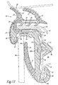
- Figure 17 shows a modification to the strip 15 shown in Figure 4 .
- the structure of the strip 15 in Figure 17 is the same as that of the strip shown in Figure 4 , with the exception that an additional metal carrier 300 is incorporated in the limb 43, which limb 43 is extruded from (and integrally extruded with) the lower side of the channel 23.
- the additional metal carrier 300 may, of course comprise materials other than metal. Any suitable rigid material could be employed.
- the additional carrier 300 is a planar elongate member which extends into and out of the page of the Figure as shown.
- the additional carrier 300 is positioned in the region generally above the resiliently deformable protrusion 49, although positioning of the additional carrier 300 at this point is not essential.
- the additional carrier 300 increases the longitudinal rigidity of the limb 43.
- the additional carrier 300 is integrally embedded within the limb 43 during the extrusion process forming the limb 43 (and other components of the strip 15).
- the strip 15 will emerge from the extruder as it is formed.
- the presence of the additional carrier 300 by increasing the longitudinal rigidity, will eliminate or reduce the tendency for the strip 15, and in particular the limb 43, to sag or bend downwards as it emerges from the extruder. This makes it easier to handle the strip 15. For example, it is easy for the strip 15 to be accurately cut to the required size.
- the sealing, trimming or guiding strip of the invention is also applicable to the front side window of a vehicle.
Landscapes
- Engineering & Computer Science (AREA)
- Mechanical Engineering (AREA)
- Seal Device For Vehicle (AREA)
- Package Frames And Binding Bands (AREA)
- Window Of Vehicle (AREA)
Claims (36)
- Eine Dichtungs-, Trimm- oder Führungsleiste für einen Fensterrahmen eines Fahrzeugs, welcher umfasst einen Längsabschnitt von extrudiertem Material (19), der sich entlang der Leiste erstreckt und einen Teil davon bildet, wobei ein Abschnitt der Leiste entlang eines Teils des Längsabschnitts durch ausgeformtes Material (63, 93, 103, 107, 200) gebildet wird, welches an das extrudierte Material (19) angeformt und dadurch damit verbunden ist; worin das extrudierte Material (19) einen Kanal (23) für die Aufnahme eines Flansches (25) des Fensterrahmens aufweist,
gekennzeichnet durch
einen steifen Verstärkungsträger (31), eingebettet in das extrudierte Material (19) in dem Bereich, der dem Kanal (23) entspricht und durch den Kanal (23), der sich entlang der Leiste erstreckt, durch angeformtes Material (63, 93, 103, 107, 200), welches eine eine Fensterscheibe (58) aufnehmende Oberfläche für die Innenseite der Fensterscheibe (58) aufweist und durch extrudiertes Materiel (19), das sich entlang des Kanals (23) erstreckt und eine eine Fensterscheibe (58) aufnehmende Oberfläche für die Außenseite der Fensterscheibe (58) aufweist und eine im allgemeinen gegenüberliegende Oberfläche, die vom Äußeren des Fahrzeugs direkt sichtbar ist, wenn sie montiert ist, wobei die beiden Oberflächen aus extrudiertem Material sich auch entlang der Leiste erstrecken. - Leiste nach Anspruch 1, worin das angeformte Material (63, 93, 103, 107, 200) derart verlängert ist, dass es eine geschlossene Schleife bildet.
- Leiste nach Anspruch 2, worin der Längsabschnitt des extrudierten Materials (19) sich über den Abschnitt der Leiste, die das angeformte Material umfasst, von der geschlossenen Schlaufe hinaus erstreckt.
- Leiste nach einem der vorangegangenen Ansprüche, worin das angeformte Material (63, 93, 103, 107, 200) mindestens eine einstückige Struktur zur Sicherung des angeformten Teils an den Fensterrahmen aufweist.
- Leiste nach Anspruch 4, worin die oder jede Struktur eine Öffnung (67, 208) in dem angeformten Teil aufweist, durch welche ein Klemmelement (69, 210) hindurchtritt.
- Leiste nach Anspruch 5, worin das Klemmelement (69, 210) an einer Glasscheibe (68) befestigt ist und die Scheibe (68) an den Fensterrahmen durch das Einführen des Klemmelements (69, 210) in die Öffnung (67, 208) in dem angeformten Teil und durch eine weitere Öffnung in Fensterrahmen gesichert werden kann.
- Leiste nach Anspruch 4, worin die oder jede Struktur ein einstückig mit dem angeformten Material (63, 93, 103, 107, 200) gebildetes Klemmelement (105) aufweist, das mit den korrespondierenden Strukturen in Fensterrahmen zusammenwirkt.
- Leiste nach Anspruch 4, worin die oder jede Struktur ein in das angeformte Material (63, 103, 107, 93, 200) eingebettetes Klemmelement (109) aufweist, das mit den entsprechenden Strukturen in Fensterrahmen zusammenwirkt.
- Leiste nach Anspruch 5 oder 6, welche ferner ein steifes Element (202) umfasst, welches in das angeformte Material (63, 103, 107, 200, 93) eingebettet ist und eine Öffnung (204) aufweist, durch welche das Klemmelement (69, 210) hindurchtritt.
- Leiste nach einem der vorhergegangenen Ansprüche, worin das extrudierte Material (19) eine Vielzahl von einstückig angeformten Strukturen (33) zur Sicherung des extrudierten Teils (19) an den Fensterrahmen aufweist.
- Leiste nach einem der vorhergehenden Ansprüche, welches ein langgestrecktes, steifes Element (95) aufweist, in welches ein Abschnitt der Leiste eingepasst ist.
- Leiste nach Anspruch 11, in welche das angeformte Material (63, 93, 103, 107, 200) in das steife Element (45) eingepasst ist, um so eine Glasscheibe (68), die in das angeformte Material (63, 93, 103, 107, 200) eingepasst ist, einzuklemmen.
- Leiste nach Anspruch 11 oder 12, in welcher das langgestreckte steife Element (95) einen weiteren Längsabschnitt von extrudiertem Material (81), das eine eine Glasscheibe (58) aufnehmenden Kanal (83) aufweist, aufnimmt.
- Leiste nach Anspruch 11, 12 oder 13, in welcher das langgestreckte steife Element (95) im Wesentlichen H-förmig ist.
- Leiste nach Anspruch 8, in welcher das eingebettete Klemmelement (109) einen steifen Bodenbereich aufweist, der sich entlang des Kanals (23) erstreckt, um so die zum Entfernen der Leiste von den Fensterrahmen erforderliche Kraft zu erhöhen.
- Leiste nach Anspruch 9, in welcher das eingebettete steife Element (202) sich entlang des Kanals (23) erstreckt, um so die zum Entfernen der Leiste vom Fensterrahmen erforderliche Kraft zu erhöhen.
- Leiste nach einem der vorangegangenen Ansprüche, in welcher das extrudierte Material (19) einen Schenkel (43) aufweist, der mindestens einen Teil des eine Glasscheibe (58) aufnehmenden Kanals bildet.
- Verfahren zum Bilden einer Dichtungs-, Trimm- oder Führungsleiste für einen Fensterrahmen, wobei die Leiste einen Längsabschnitt des Materials (19), welcher einen Teil der Leiste bildet, umfasst, und welches einen Kanal (23) für die Aufnahme eines Flansches (25) des Fensterrahmens und einen steifen Verstärkungsträger (31) eingebettet in das Material (19) in den Bereich, der dem Kanal (23) entspricht, aufweist; und wobei die Leiste ferner eine erste eine Glasscheibe (58) aufnehmende Oberfläche für die Innenseite der Glasscheibe (58), eine zweite eine Glasscheibe (58) aufnehmende Oberfläche für die Außenseite der Glasscheibe (58) und eine im allgemeinen gegenüberliegende Oberfläche, direkt sichtbar von der Außenseite des Fahrzeugs, wenn sie montiert ist, aufweist; wobei das Verfahren umfasst Extrudieren des Material (19), um den Längsabschnitt zu bilden, Entfernen eines Teils des extrudierten Materials nur entlang des Längsabschnitts, und Ersetzen des Abschnittes durch angeformtes Material (63, 93, 103, 107, 200), welches auf das extrudierte Material (19) angeformt und dabei mit diesem verbunden wird, wobei der Kanal (23) als Teil der Leiste nach dem Entfermen des Teils des extrudierten Materials zurückbleibt, worin das angeformte Material (63, 93, 103, 107, 200) die erste eine Fensterscheibe (53) aufnehmende Oberfläche bildet und worin das extrudierte Material (19) sich vom Kanal (23) erstreckt und die zweite eine Fensterscheibe (58) aufnehmende Oberfläche und eine im allgemeinen gegenüberliegende Oberfläche bildet, wobei diese beiden Oberflächen aus extrudiertem Material auch als Teil der Leiste nach dem Entfernen des Abschnittes des extrudierten Materials zurückbleiben.
- Verfahren nach Anspruch 18, in welchem das geformte Material (63, 93, 103, 107, 200) sich derart verlängert ist, dass es eine geschlossene Schleife bildet.
- Verfahren nach Anspruch 19, in welchem sich der Längsabschnitt des extrudierten Materials (19) über den entfernten Abschnitt hinaus von der geschlossenen Schleife erstreckt.
- Verfahren nach einem der Ansprüche 18 bis 20, in welchemdas angeformte Material (63, 93, 103, 107, 200) mindestens eine einstückige Struktur zur Sicherung des angeformten Teils an den Fensterrahmen aufweist.
- Verfahren nach Anspruch 21, in welchem die oder jede Struktur eine Öffnung (67, 208) in dem angeformten Teil (63, 93, 103, 107, 200), durch welches ein Klemmelement (69, 201) hindurchtritt, umfasst.
- Verfahren nach Anspruch 22, in welchem das Klemmelement (69, 210) an einer Glasscheibe (68) befestigt ist und die Glasscheibe (68) an den Fensterrahmen durch Hindurchtreten des Klemmelement (69, 210) durch die Öffnung (67, 208) in den angeformten Teil (63, 93, 103, 107, 200) und durch eine weitere Öffnung im Fensterrahmen gesichert werden kann.
- Verfahren nach Anspruch 21, in welchem die oder jede Struktur ein Klemmelement (105) aufweist, das einstückig mit dem angeformten Material (63, 93, 103, 107, 200) gebildet ist, um mit den korrespondierenden Strukturen des Fensterrahmens zusammenzuwirken.
- Verfahren nach Anspruch 21, in welchem die oder jede Struktur ein Klemmelement (109) aufweist, welche in das angeformte Material (63, 93, 103, 107, 200) eingebettet ist, um mit den korrespondierenden Strukturen des Fensterrahmens zusammenzuwirken.
- Verfahren nach einem der Ansprüche 22 oder 23, in welchen ein steifes Element (202) in das geformte Material (63, 93, 103, 107, 200) eingebettet ist ud eine Öffnung (4) darin aufweist, durch welche das Klemmelement (69, 210) durchtritt.
- Verfahren nach einem der Ansprüche 18 bis 26, in welchem das extrudierte Material (19) eine Vielzahl von Integrierten Strukturen (33) zum Sichern des extrudierten Teils (19) an den Fensterrahmen aufweist.
- Verfahren nach einem der Ansprüche 18 bis 27, welches das Zurverfügungstellen eines gestreckten steifen Elements (95), in welches ein Abschnitt der Leiste eingepasst ist, umfasst.
- Verfahren nach Anspruch 28, in welchem das angeformte Material (63, 93, 103, 107, 200) in das gestreckte steife Element (95) eingepasst ist, um so eine Glasscheibe (68), die in das geformte Material (63, 93, 103, 107, 200) eingepasst ist, einzuklemmen.
- Verfahren nach Anspruch 28 oder 29, in welchem das gestreckte steife Element (95) auch einen weiteren Längsabschnitt des extrudierten Materials (81) mit einem eine Glasscheibe (58) aufnehmenden Kanal (83) aufnimmt.
- Verfahren nach Anspruch 28, 29 oder 30, in welchem das steife Element (95) im Wesentlichen H-förmig ist.
- Verfahren nach Anspruch 25, in welchem das eingebettete Klemmelement (109) einen steifen Bodenbereich umfasst, der sich in Richtung Kanal (23) erstreckt, um so die zum Entfernen der Leiste vom Fensterrahmen erforderliche Kraft zu erhöhen.
- Verfahren nach Anspruch 26, in welchem das eingebettete steife Element (202) sich in Richtung des Kanals (23) erstreckt, um so die zum Entfernen der Leiste aus den Fensterrahmen erforderliche Kraft zu erhöhen.
- Verfahren nach einem der Ansprüche 18 bis 33, in welchem das extrudierten Material (19) einen Schenkel (43) aufweist, welcher mindestens einen Teil eines eine Glasscheibe (58) aufnehmenden Kanals bildet, wobei ein Teil des die Glasscheibe (58) aufnehmenden Kanals durch Entfernen des Abschnittes vom extrudierten Material entfernt ist.
- Verfahren nach Anspruch 34, in welchem der Schenkel (43) ein darin eingebettetes steifes Element (300) aufweist zum Reduzieren der Neigung des Schenkels (43), sich zu biegen, wenn es aus einem zum Herstellen der Leiste verwendeten Extruder austritt.
- Leiste nach Anspruch 17, in welcher der Schenkel (43) ein darin eingebettetes steifes Element (300) aufweist, um die Neigung des Schenkels (43), sich zu biegen, zu reduzieren, wenn es aus einem zum Herstellen der Leiste verwendeten Extruder austritt.
Priority Applications (2)
| Application Number | Priority Date | Filing Date | Title |
|---|---|---|---|
| EP05019077A EP1607255A3 (de) | 2002-10-02 | 2003-10-02 | Dichtungs-, Zier- und Führungsleisten |
| DE60320276.4T DE60320276T9 (de) | 2002-10-02 | 2003-10-02 | Dichtungs-, zier- oder führungsstreifen |
Applications Claiming Priority (5)
| Application Number | Priority Date | Filing Date | Title |
|---|---|---|---|
| GB0222817 | 2002-10-02 | ||
| GB0222817A GB2393752A (en) | 2002-10-02 | 2002-10-02 | Extruded sealing strip, with part of the section replaced by moulded material over some of the length |
| GB0305476 | 2003-03-10 | ||
| GBGB0305476.4A GB0305476D0 (en) | 2002-10-02 | 2003-03-10 | Sealing,trimming or guiding strips |
| PCT/IB2003/004353 WO2004030965A1 (en) | 2002-10-02 | 2003-10-02 | Sealing, trimming or guiding strips |
Related Child Applications (2)
| Application Number | Title | Priority Date | Filing Date |
|---|---|---|---|
| EP05019077A Division EP1607255A3 (de) | 2002-10-02 | 2003-10-02 | Dichtungs-, Zier- und Führungsleisten |
| EP05019077A Division-Into EP1607255A3 (de) | 2002-10-02 | 2003-10-02 | Dichtungs-, Zier- und Führungsleisten |
Publications (3)
| Publication Number | Publication Date |
|---|---|
| EP1545920A1 EP1545920A1 (de) | 2005-06-29 |
| EP1545920B1 true EP1545920B1 (de) | 2008-04-09 |
| EP1545920B2 EP1545920B2 (de) | 2016-01-20 |
Family
ID=32071245
Family Applications (1)
| Application Number | Title | Priority Date | Filing Date |
|---|---|---|---|
| EP03799047.0A Expired - Lifetime EP1545920B2 (de) | 2002-10-02 | 2003-10-02 | Dichtungs-, zier- oder führungsstreifen |
Country Status (7)
| Country | Link |
|---|---|
| US (1) | US8479449B2 (de) |
| EP (1) | EP1545920B2 (de) |
| JP (1) | JP2006502048A (de) |
| AT (1) | ATE391625T1 (de) |
| AU (1) | AU2003265076A1 (de) |
| DE (1) | DE20321549U1 (de) |
| WO (1) | WO2004030965A1 (de) |
Cited By (1)
| Publication number | Priority date | Publication date | Assignee | Title |
|---|---|---|---|---|
| EP4417449A1 (de) * | 2023-02-16 | 2024-08-21 | CQLT SaarGummi Technologies S.à.r.l. | Dichtungsprofil für ein kraftfahrzeug, dichtungsanordnung und verfahren zur herstellung eines dichtungsprofils |
Families Citing this family (49)
| Publication number | Priority date | Publication date | Assignee | Title |
|---|---|---|---|---|
| DE10247015B4 (de) * | 2002-10-09 | 2005-02-03 | Metzeler Automotive Profile Systems Gmbh | Dichtungsprofil mit Zierleiste |
| DE10347221A1 (de) * | 2003-10-10 | 2005-05-04 | Bayerische Motoren Werke Ag | Dichtungssystem für eine Kraftfahrzeugtür |
| GB2419371A (en) * | 2004-10-20 | 2006-04-26 | Gdx Automotive Rehburg Gmbh & | Sealing, trimming or guiding strips |
| US20060086053A1 (en) * | 2004-10-27 | 2006-04-27 | Peter John Ellis | Lightweight glass-run channels |
| WO2006067622A1 (en) * | 2004-12-23 | 2006-06-29 | Gdx Automotive Rehburg Gmbh & Co. Kg | Sealing or guiding assemblies and methods of making them |
| US20060156632A1 (en) * | 2005-01-18 | 2006-07-20 | Ruppert Gerald Y | Window surround |
| DE602006013288D1 (de) * | 2005-04-04 | 2010-05-12 | Henniges Automotive Sealing Sy | Dichtungs- oder führungsanordnungen für fenster und montageverfahren |
| ES2267394B1 (es) * | 2005-07-14 | 2007-10-16 | Mollertech Orense, S.L. | Sistema de aislamiento del compartimiento motor mediante una pieza montable multimaterial. |
| DE102006021190B4 (de) * | 2006-05-06 | 2008-08-14 | GM Global Technology Operations, Inc., Detroit | Dichtungsprofil |
| DE202006010859U1 (de) * | 2006-07-12 | 2006-08-31 | Meteor Gummiwerke K.H. Bädje GmbH & Co. KG | Dichtungsanordnung |
| ATE425890T1 (de) * | 2007-01-12 | 2009-04-15 | Rainforest R & D Ltd | Befestigungsleiste zur verwendung mit einer abdichtung zum abdichten eines fensters einer fahrzeugtur |
| US8312675B2 (en) * | 2008-05-22 | 2012-11-20 | Honda Motor Co., Ltd. | Pinch sensor for sliding door |
| FR2956068B1 (fr) * | 2010-02-08 | 2012-04-20 | Hutchinson | Enjoliveur exterieur pour cadre de porte de vehicule automobile, et module d'etancheite l'incorporant |
| US8474188B2 (en) * | 2010-08-16 | 2013-07-02 | Henniges Automotive Sealing Systems North America, Inc. | Carrier having a living hinge |
| JP2012106715A (ja) * | 2010-10-26 | 2012-06-07 | Aisin Seiki Co Ltd | ガラスラン一体モール |
| DE102012000703A1 (de) * | 2012-01-16 | 2013-07-18 | Gm Global Technology Operations, Llc | Dichteinrichtung |
| USD695151S1 (en) * | 2012-04-27 | 2013-12-10 | Qoros Automotive Co., Ltd. | Vehicle |
| US8919846B2 (en) | 2012-05-04 | 2014-12-30 | Srg Global, Inc. | Daylight opening system for vehicle |
| US9114693B2 (en) * | 2012-05-04 | 2015-08-25 | Srg Global, Inc. | Daylight opening system |
| USD719065S1 (en) * | 2012-07-27 | 2014-12-09 | Toyota Jidosha Kabushiki Kaisha | Automobile and/or toy replica thereof |
| DE102013101896A1 (de) * | 2013-02-26 | 2014-08-28 | Bayerische Motoren Werke Aktiengesellschaft | Dichtungsprofil |
| DE102014107166A1 (de) * | 2014-05-21 | 2015-12-17 | Cqlt Saargummi Technologies S.À.R.L. | Anordnung aus einem Verbundteil und Rahmenteilen eines Fahrzeugtürfensters |
| US9079480B1 (en) * | 2014-06-06 | 2015-07-14 | Toyota Motor Engineering & Manufacturing North America, Inc. | Glass run weather strip assembly |
| FR3025164B1 (fr) * | 2014-08-28 | 2018-02-02 | Faiveley Transport Tours | Systeme d'etancheite pour un ouvrant comportant un profile recevant un joint d'etancheite verrouille par une cle coulissante |
| JP6566745B2 (ja) * | 2015-06-30 | 2019-08-28 | 西川ゴム工業株式会社 | 自動車用ドアのシール材 |
| JP6585952B2 (ja) * | 2015-07-28 | 2019-10-02 | 西川ゴム工業株式会社 | 自動車ドア用モールの取付構造 |
| JP2017100613A (ja) * | 2015-12-03 | 2017-06-08 | 三菱自動車工業株式会社 | ドアのガラス取付構造 |
| US11155012B2 (en) | 2016-01-26 | 2021-10-26 | Henniges Automotive Sealing Systems North America, Inc. | Method of manufacturing a seal assembly for a vehicle |
| JP6504409B2 (ja) * | 2016-03-11 | 2019-04-24 | 豊田合成株式会社 | ガラスラン |
| US10569629B2 (en) * | 2016-04-12 | 2020-02-25 | Nishikawa Rubber Co., Ltd. | Glass run for automobile door |
| JP6700979B2 (ja) * | 2016-05-31 | 2020-05-27 | 西川ゴム工業株式会社 | 自動車ドア用グラスラン |
| JP6936559B2 (ja) * | 2016-06-20 | 2021-09-15 | 西川ゴム工業株式会社 | 自動車ドア用グラスラン |
| CN107685615B (zh) * | 2016-08-03 | 2022-05-03 | 西川橡胶工业股份有限公司 | 玻璃滑槽 |
| DE102016117957A1 (de) * | 2016-09-23 | 2018-03-29 | Cooper Standard GmbH | Dichtungsanordnung für ein Kraftfahrzeugfenster, Dichtungsverbund und Verfahren zum Herstellen eines Dichtungsverbundes |
| JP6890762B2 (ja) * | 2017-05-30 | 2021-06-18 | 株式会社アイシン | タッチセンサユニット |
| DE102018110218A1 (de) * | 2017-06-12 | 2018-12-13 | Cqlt Saargummi Technologies S.À.R.L. | Dichtungsanordnung zur Führung und Abdichtung einer vertikal bewegbaren Fahrzeugfensterscheibe |
| US10723050B2 (en) * | 2017-11-29 | 2020-07-28 | Henniges Automotive Sealing Systems North America, Inc. | Method of manufacturing a window seal assembly with a molded bracket |
| JP7018758B2 (ja) * | 2017-12-13 | 2022-02-14 | 西川ゴム工業株式会社 | 自動車ドア用シール構造 |
| KR102634350B1 (ko) * | 2018-10-23 | 2024-02-07 | 현대자동차주식회사 | 차량용 도어 글래스 런 |
| JP7156905B2 (ja) * | 2018-10-29 | 2022-10-19 | 西川ゴム工業株式会社 | 自動車ドア用シール材 |
| CN111605622B (zh) * | 2019-02-22 | 2024-03-26 | 标致雪铁龙汽车股份有限公司 | 一种车辆的c柱总成及车辆 |
| FR3099420B1 (fr) * | 2019-07-30 | 2021-08-27 | Renault Sas | Joint d'étanchéité comprenant un dispositif lumineux |
| JP7321107B2 (ja) * | 2020-01-09 | 2023-08-04 | 西川ゴム工業株式会社 | 自動車用ドアのシール構造 |
| JP7339892B2 (ja) * | 2020-01-09 | 2023-09-06 | 西川ゴム工業株式会社 | 自動車用ドアのシール構造 |
| DE102021101121A1 (de) * | 2020-01-29 | 2021-07-29 | Nishikawa Rubber Co., Ltd. | Eckteilstruktur einer glasscheibenführung |
| JP7397725B2 (ja) | 2020-03-13 | 2023-12-13 | 西川ゴム工業株式会社 | ウェザストリップ |
| DE102020126093A1 (de) * | 2020-10-06 | 2022-04-07 | Cqlt Saargummi Technologies S.À.R.L. | Dichtungsprofil, Dichtungsanordnung sowie Befestigungsverfahren |
| US12240300B2 (en) | 2021-01-12 | 2025-03-04 | Henniges Automotive Sealing Systems North America, Inc. | Below belt seal assembly, associated window sealing system, and method for manufacturing same |
| US12365225B2 (en) * | 2022-09-24 | 2025-07-22 | Cooper-Standard Automotive, Inc. | Outer belt with molded snap-fit retention feature |
Family Cites Families (60)
| Publication number | Priority date | Publication date | Assignee | Title |
|---|---|---|---|---|
| DE3126491A1 (de) | 1981-07-04 | 1983-01-20 | Volkswagenwerk Ag, 3180 Wolfsburg | "fahrzeugtuer mit einem fenster" |
| GB2140068B (en) | 1983-05-20 | 1986-03-19 | Draftex Ind Ltd | Window glass mounting |
| JPS6076420A (ja) † | 1983-10-03 | 1985-04-30 | Kinugawa Rubber Ind Co Ltd | 自動車用グラスランの取付構造 |
| DE3336733A1 (de) | 1983-10-08 | 1985-04-25 | Continental Gummi-Werke Ag, 3000 Hannover | Verfahren und vorrichtung zum verbinden der enden von dichtungsstreifen |
| DE3342362A1 (de) * | 1983-11-23 | 1985-06-05 | Metzeler Kautschuk GmbH, 8000 München | Vorrichtung zur fuehrung und halterung einer fensterscheibe in einem kraftfahrzeug |
| US4591203A (en) * | 1984-04-02 | 1986-05-27 | General Motors Corporation | Modular window assembly |
| DE3413029A1 (de) * | 1984-04-06 | 1985-10-17 | Adam Opel AG, 6090 Rüsselsheim | Fensterscheibe fuer kraftfahrzeuge |
| JPH0349049Y2 (de) * | 1985-03-13 | 1991-10-21 | ||
| US4800681A (en) | 1986-02-06 | 1989-01-31 | Sheller-Globe, Inc. | Sealing and guiding element for flush mounted movable automobile window |
| US4894954A (en) * | 1987-12-24 | 1990-01-23 | Toyoda Gosei Co., Ltd. | Weather strip for vehicle |
| JPH075025B2 (ja) * | 1988-08-10 | 1995-01-25 | 豊田合成株式会社 | 車両用ドアガラスラン |
| FR2642374B1 (fr) | 1989-01-27 | 1991-05-17 | Mesnil Ets | Ensemble modulaire de glace de custode pour porte d'automobile et son procede de fabrication |
| DE4002026A1 (de) | 1989-03-09 | 1990-09-13 | Metzeler Gmbh | Profilrahmen aus elastomerem material und verfahren zu seiner herstellung |
| GB2233377B (en) * | 1989-06-21 | 1993-08-25 | Draftex Ind Ltd | Sealing strips |
| JPH0326646U (de) * | 1989-07-26 | 1991-03-18 | ||
| GB2237768B (en) | 1989-11-10 | 1993-06-02 | Draftex Ind Ltd | Sealing strips and methods and apparatus for making them |
| US5127193A (en) * | 1990-03-16 | 1992-07-07 | Toyoda Gosei Co., Ltd. | Weather strip for motor vehicle |
| US5209019A (en) * | 1990-09-27 | 1993-05-11 | Tokai Kogyo Kabushiki Kaisha | Seal structure for automobile doors |
| US5269101A (en) * | 1991-07-29 | 1993-12-14 | Toyoda Gosei Co., Ltd. | Automotive weatherstrip |
| JPH0648183A (ja) * | 1992-01-31 | 1994-02-22 | Nishikawa Rubber Co Ltd | ウェザーストリップ |
| FR2689441B1 (fr) | 1992-04-02 | 1995-08-11 | Technistan | Procede de surmoulage par injection d'un joint d'etancheite et moule pour la mise en óoeuvre du procede. |
| FR2694243B1 (fr) | 1992-07-29 | 1994-10-21 | Technistan Gie | Ensemble d'habillage de portière. |
| US5317835A (en) * | 1992-09-10 | 1994-06-07 | Gencorp Inc. | Window enclosure for an automotive upper door frame |
| FR2696376B1 (fr) | 1992-10-05 | 1994-12-23 | Technistan | Dispositif d'étanchéité pour panneau fixe et vitre mobile de véhicule automobile. |
| JPH06278461A (ja) | 1993-03-26 | 1994-10-04 | Kinugawa Rubber Ind Co Ltd | 自動車のリヤドア構造 |
| DE4339033C2 (de) * | 1993-11-15 | 1997-08-21 | Metzeler Automotive Profiles | Anordnung zum gleichzeitigen Abdichten einer Türscheibe und der Türöffnung an einem Kraftfahrzeug |
| US5433038A (en) * | 1993-12-03 | 1995-07-18 | Gencorp Inc. | Vehicle window weather sealing strip with retaining clip |
| US5493814A (en) * | 1994-04-18 | 1996-02-27 | The Standard Products Company | Weatherstrip assembly including a glass run channel and belt weatherstrip with decorative cover |
| JP3201162B2 (ja) | 1994-09-01 | 2001-08-20 | 日産自動車株式会社 | 自動車のドアガラス支持構造 |
| US5566510A (en) * | 1994-10-26 | 1996-10-22 | Gencorp Inc. | Molded glass run channel corner assembly |
| US5820198A (en) † | 1995-03-03 | 1998-10-13 | Toyoda Gosei Co., Ltd. | Weather strip for motor vehicle and method for manufacturing the same |
| FR2731765B1 (fr) | 1995-03-17 | 1997-06-06 | Standard Products Ind | Joint d'etancheite ainsi que son procede de fabrication |
| GB9512803D0 (en) † | 1995-06-23 | 1995-08-23 | Rover Group | Vehicle window assembly |
| JPH09123760A (ja) * | 1995-11-02 | 1997-05-13 | Toyoda Gosei Co Ltd | ドアウエザストリップの取付構造 |
| GB9608477D0 (en) | 1996-04-25 | 1996-07-03 | Draftex Ind Ltd | Sealing, trimming or guiding strips |
| CZ298470B6 (cs) † | 1996-04-25 | 2007-10-10 | Gdx North America Inc. | Lemovací, vodicí a tesnicí páska |
| US5846463A (en) | 1996-06-13 | 1998-12-08 | Kingston-Warren Corporation | Encapsulated fixed window module for a motor vehicle |
| DE19632843C1 (de) | 1996-08-14 | 1997-09-25 | Metzeler Automotive Profiles | Profilrahmen für eine bewegliche Fensterscheibe |
| US6023888A (en) * | 1996-09-25 | 2000-02-15 | Schlegel Corporation | Door and window channel seal |
| JPH10129263A (ja) | 1996-10-28 | 1998-05-19 | Nissan Motor Co Ltd | 自動車のドアサッシュ構造 |
| JP3829421B2 (ja) * | 1996-12-24 | 2006-10-04 | 豊田合成株式会社 | 自動車用ウエザストリップ |
| JP3814946B2 (ja) * | 1997-05-27 | 2006-08-30 | 豊田合成株式会社 | 自動車用ドアガラスランのコーナ部成形方法 |
| US6395355B1 (en) * | 1997-10-30 | 2002-05-28 | Toyoda Gosei Co., Ltd. | Weather strip |
| JP3596258B2 (ja) * | 1997-11-06 | 2004-12-02 | 豊田合成株式会社 | ウエザストリップのコーナ部成形方法 |
| FR2782957B1 (fr) * | 1998-09-03 | 2000-10-20 | Hutchinson | Coulisse pour portiere automobile et son procede de mise en place, notamment par cintrage differentiel |
| JP3633332B2 (ja) | 1999-01-12 | 2005-03-30 | 豊田合成株式会社 | 固定窓用ウエザストリップ |
| DE19912176A1 (de) † | 1999-03-18 | 2000-09-21 | Volkswagen Ag | Dichtungsanordnung für ein Bauteil nach Art einer Tür oder Klappe |
| JP3218394B2 (ja) * | 1999-09-03 | 2001-10-15 | 西川ゴム工業株式会社 | 自動車ドア下部のシール構造 |
| US6493992B2 (en) * | 1999-11-30 | 2002-12-17 | Toyoda Gosei Co., Ltd. | Glass run and attachment structure therefor |
| JP4438221B2 (ja) * | 2000-03-29 | 2010-03-24 | 豊田合成株式会社 | ドアシール構造 |
| GB2361020A (en) | 2000-04-03 | 2001-10-10 | Standard Products Co | Glass run seal |
| US6370824B1 (en) * | 2000-05-10 | 2002-04-16 | Hutchinson Sealing Systems, Inc. | Automotive vehicle seal with decorative trim sealing surface |
| JP2001322437A (ja) | 2000-05-16 | 2001-11-20 | Kinugawa Rubber Ind Co Ltd | ドアグラスランのコーナー部シール構造 |
| DE10058497B4 (de) * | 2000-11-24 | 2004-12-16 | Metzeler Automotive Profile Systems Gmbh | Dichtungsanordnung |
| DE10159251C1 (de) | 2001-12-03 | 2003-04-30 | Metzeler Automotive Profile | Aufnahmerahmen für eine stationäre Fensterscheibe |
| US6817651B2 (en) * | 2002-05-01 | 2004-11-16 | Schlegel Corporation | Modular vehicular window seal assembly |
| FR2843076B1 (fr) * | 2002-08-02 | 2007-02-09 | Hutchinson | Profile d'etancheite formant coulisse pour vitrage de vehicule a moteur. |
| JP4054892B2 (ja) * | 2002-08-09 | 2008-03-05 | 東海興業株式会社 | 車両用ドアの車内側ウエザーストリップ |
| JP3890565B2 (ja) * | 2003-03-14 | 2007-03-07 | 西川ゴム工業株式会社 | ドアウエザーストリップの組付構造 |
| FR2863212B1 (fr) * | 2003-12-09 | 2006-02-24 | Hutchinson | Procede pour fabriquer un joint d'etancheite, en particulier une coulisse pour vitrage de vehicule a moteur, et joint ainsi fabrique |
-
2003
- 2003-10-02 DE DE20321549U patent/DE20321549U1/de not_active Expired - Lifetime
- 2003-10-02 JP JP2005500076A patent/JP2006502048A/ja active Pending
- 2003-10-02 WO PCT/IB2003/004353 patent/WO2004030965A1/en not_active Ceased
- 2003-10-02 EP EP03799047.0A patent/EP1545920B2/de not_active Expired - Lifetime
- 2003-10-02 AT AT03799047T patent/ATE391625T1/de not_active IP Right Cessation
- 2003-10-02 AU AU2003265076A patent/AU2003265076A1/en not_active Abandoned
- 2003-10-03 US US10/530,325 patent/US8479449B2/en not_active Expired - Fee Related
Cited By (1)
| Publication number | Priority date | Publication date | Assignee | Title |
|---|---|---|---|---|
| EP4417449A1 (de) * | 2023-02-16 | 2024-08-21 | CQLT SaarGummi Technologies S.à.r.l. | Dichtungsprofil für ein kraftfahrzeug, dichtungsanordnung und verfahren zur herstellung eines dichtungsprofils |
Also Published As
| Publication number | Publication date |
|---|---|
| AU2003265076A1 (en) | 2004-04-23 |
| ATE391625T1 (de) | 2008-04-15 |
| WO2004030965A1 (en) | 2004-04-15 |
| JP2006502048A (ja) | 2006-01-19 |
| US8479449B2 (en) | 2013-07-09 |
| US20070101656A1 (en) | 2007-05-10 |
| DE20321549U1 (de) | 2008-04-03 |
| EP1545920A1 (de) | 2005-06-29 |
| EP1545920B2 (de) | 2016-01-20 |
Similar Documents
| Publication | Publication Date | Title |
|---|---|---|
| EP1545920B1 (de) | Dichtungs-, zier- oder führungsstreifen | |
| EP1607255A2 (de) | Dichtungs-, Zier- und Führungsleisten | |
| US8033057B2 (en) | Sealing arrangement for sealing and guiding a powered window pane, particularly of a motor vehicle | |
| EP0587428B1 (de) | Fensterformteil für Kraftfahrzeugtür | |
| US6082048A (en) | Sealing, trimming or guiding strips | |
| EP0412782A2 (de) | Führungsschiene für Scheibe mit integriertem Verkleidungsteil | |
| US5475947A (en) | Flexible sealing unit for movable windows | |
| GB2419371A (en) | Sealing, trimming or guiding strips | |
| EP1567382B1 (de) | Fensterdichtungs- und führungsanordnungen | |
| US20070194539A1 (en) | Sealing, trimming or guiding strips | |
| EP1567380B1 (de) | Dichtungs-, begrenzungs- oder führungsbänder und verstärkungen dafür | |
| EP1843910B1 (de) | Dichtung oder führungseinrichtung und verfahren zur dessen herstellung | |
| EP0691231B1 (de) | Dichtungselement für Fenster und Befestigungsvorrichtung | |
| WO2008084320A1 (en) | Sealing assembly for sliding window panes in vehicle doors | |
| WO2007020525A1 (en) | Window sealing and guiding arrangements for vehicle doors and windows | |
| EP1866177B1 (de) | Dichtungs- oder führungsanordnungen für fenster und montageverfahren | |
| EP1490242A1 (de) | Dichtung oder führungseinrichtung und verfahren | |
| JP2001047948A (ja) | 自動車用ウエザーストリップ | |
| JPH02286445A (ja) | ドリップチャンネル用ウエザーストリップ | |
| GB2425142A (en) | Sealing or guiding assemblies and methods of making them |
Legal Events
| Date | Code | Title | Description |
|---|---|---|---|
| PUAI | Public reference made under article 153(3) epc to a published international application that has entered the european phase |
Free format text: ORIGINAL CODE: 0009012 |
|
| 17P | Request for examination filed |
Effective date: 20050323 |
|
| AK | Designated contracting states |
Kind code of ref document: A1 Designated state(s): AT BE BG CH CY CZ DE DK EE ES FI FR GB GR HU IE IT LI LU MC NL PT RO SE SI SK TR |
|
| AX | Request for extension of the european patent |
Extension state: AL LT LV MK |
|
| DAX | Request for extension of the european patent (deleted) | ||
| GRAP | Despatch of communication of intention to grant a patent |
Free format text: ORIGINAL CODE: EPIDOSNIGR1 |
|
| GRAS | Grant fee paid |
Free format text: ORIGINAL CODE: EPIDOSNIGR3 |
|
| GRAA | (expected) grant |
Free format text: ORIGINAL CODE: 0009210 |
|
| AK | Designated contracting states |
Kind code of ref document: B1 Designated state(s): AT BE BG CH CY CZ DE DK EE ES FI FR GB GR HU IE IT LI LU MC NL PT RO SE SI SK TR |
|
| REG | Reference to a national code |
Ref country code: GB Ref legal event code: FG4D |
|
| REG | Reference to a national code |
Ref country code: CH Ref legal event code: EP |
|
| REG | Reference to a national code |
Ref country code: IE Ref legal event code: FG4D |
|
| REF | Corresponds to: |
Ref document number: 60320276 Country of ref document: DE Date of ref document: 20080521 Kind code of ref document: P |
|
| PG25 | Lapsed in a contracting state [announced via postgrant information from national office to epo] |
Ref country code: SI Free format text: LAPSE BECAUSE OF FAILURE TO SUBMIT A TRANSLATION OF THE DESCRIPTION OR TO PAY THE FEE WITHIN THE PRESCRIBED TIME-LIMIT Effective date: 20080409 |
|
| NLV1 | Nl: lapsed or annulled due to failure to fulfill the requirements of art. 29p and 29m of the patents act | ||
| PG25 | Lapsed in a contracting state [announced via postgrant information from national office to epo] |
Ref country code: BG Free format text: LAPSE BECAUSE OF FAILURE TO SUBMIT A TRANSLATION OF THE DESCRIPTION OR TO PAY THE FEE WITHIN THE PRESCRIBED TIME-LIMIT Effective date: 20080709 Ref country code: FI Free format text: LAPSE BECAUSE OF FAILURE TO SUBMIT A TRANSLATION OF THE DESCRIPTION OR TO PAY THE FEE WITHIN THE PRESCRIBED TIME-LIMIT Effective date: 20080409 Ref country code: ES Free format text: LAPSE BECAUSE OF FAILURE TO SUBMIT A TRANSLATION OF THE DESCRIPTION OR TO PAY THE FEE WITHIN THE PRESCRIBED TIME-LIMIT Effective date: 20080720 Ref country code: PT Free format text: LAPSE BECAUSE OF FAILURE TO SUBMIT A TRANSLATION OF THE DESCRIPTION OR TO PAY THE FEE WITHIN THE PRESCRIBED TIME-LIMIT Effective date: 20080909 Ref country code: NL Free format text: LAPSE BECAUSE OF FAILURE TO SUBMIT A TRANSLATION OF THE DESCRIPTION OR TO PAY THE FEE WITHIN THE PRESCRIBED TIME-LIMIT Effective date: 20080409 |
|
| PG25 | Lapsed in a contracting state [announced via postgrant information from national office to epo] |
Ref country code: AT Free format text: LAPSE BECAUSE OF FAILURE TO SUBMIT A TRANSLATION OF THE DESCRIPTION OR TO PAY THE FEE WITHIN THE PRESCRIBED TIME-LIMIT Effective date: 20080409 |
|
| PLBI | Opposition filed |
Free format text: ORIGINAL CODE: 0009260 |
|
| EN | Fr: translation not filed | ||
| PG25 | Lapsed in a contracting state [announced via postgrant information from national office to epo] |
Ref country code: CZ Free format text: LAPSE BECAUSE OF FAILURE TO SUBMIT A TRANSLATION OF THE DESCRIPTION OR TO PAY THE FEE WITHIN THE PRESCRIBED TIME-LIMIT Effective date: 20080409 Ref country code: SE Free format text: LAPSE BECAUSE OF FAILURE TO SUBMIT A TRANSLATION OF THE DESCRIPTION OR TO PAY THE FEE WITHIN THE PRESCRIBED TIME-LIMIT Effective date: 20080709 Ref country code: DK Free format text: LAPSE BECAUSE OF FAILURE TO SUBMIT A TRANSLATION OF THE DESCRIPTION OR TO PAY THE FEE WITHIN THE PRESCRIBED TIME-LIMIT Effective date: 20080409 |
|
| 26 | Opposition filed |
Opponent name: METZELER AUTOMOTIVE PROFILE SYSTEMS GMBH Effective date: 20090109 |
|
| PLAX | Notice of opposition and request to file observation + time limit sent |
Free format text: ORIGINAL CODE: EPIDOSNOBS2 |
|
| PG25 | Lapsed in a contracting state [announced via postgrant information from national office to epo] |
Ref country code: RO Free format text: LAPSE BECAUSE OF FAILURE TO SUBMIT A TRANSLATION OF THE DESCRIPTION OR TO PAY THE FEE WITHIN THE PRESCRIBED TIME-LIMIT Effective date: 20080409 Ref country code: BE Free format text: LAPSE BECAUSE OF FAILURE TO SUBMIT A TRANSLATION OF THE DESCRIPTION OR TO PAY THE FEE WITHIN THE PRESCRIBED TIME-LIMIT Effective date: 20080409 Ref country code: SK Free format text: LAPSE BECAUSE OF FAILURE TO SUBMIT A TRANSLATION OF THE DESCRIPTION OR TO PAY THE FEE WITHIN THE PRESCRIBED TIME-LIMIT Effective date: 20080409 |
|
| REG | Reference to a national code |
Ref country code: DE Ref legal event code: 8363 Ref document number: 60320276 Country of ref document: DE |
|
| PG25 | Lapsed in a contracting state [announced via postgrant information from national office to epo] |
Ref country code: EE Free format text: LAPSE BECAUSE OF FAILURE TO SUBMIT A TRANSLATION OF THE DESCRIPTION OR TO PAY THE FEE WITHIN THE PRESCRIBED TIME-LIMIT Effective date: 20080409 Ref country code: FR Free format text: LAPSE BECAUSE OF FAILURE TO SUBMIT A TRANSLATION OF THE DESCRIPTION OR TO PAY THE FEE WITHIN THE PRESCRIBED TIME-LIMIT Effective date: 20090130 |
|
| PLAF | Information modified related to communication of a notice of opposition and request to file observations + time limit |
Free format text: ORIGINAL CODE: EPIDOSCOBS2 |
|
| PG25 | Lapsed in a contracting state [announced via postgrant information from national office to epo] |
Ref country code: MC Free format text: LAPSE BECAUSE OF NON-PAYMENT OF DUE FEES Effective date: 20081031 |
|
| REG | Reference to a national code |
Ref country code: CH Ref legal event code: PL |
|
| GBPC | Gb: european patent ceased through non-payment of renewal fee |
Effective date: 20081002 |
|
| PG25 | Lapsed in a contracting state [announced via postgrant information from national office to epo] |
Ref country code: IT Free format text: LAPSE BECAUSE OF FAILURE TO SUBMIT A TRANSLATION OF THE DESCRIPTION OR TO PAY THE FEE WITHIN THE PRESCRIBED TIME-LIMIT Effective date: 20080409 |
|
| PLBB | Reply of patent proprietor to notice(s) of opposition received |
Free format text: ORIGINAL CODE: EPIDOSNOBS3 |
|
| PG25 | Lapsed in a contracting state [announced via postgrant information from national office to epo] |
Ref country code: CY Free format text: LAPSE BECAUSE OF FAILURE TO SUBMIT A TRANSLATION OF THE DESCRIPTION OR TO PAY THE FEE WITHIN THE PRESCRIBED TIME-LIMIT Effective date: 20080409 |
|
| RAP2 | Party data changed (patent owner data changed or rights of a patent transferred) |
Owner name: HENNIGES AUTOMOTIVE SEALING SYSTEMS NORTH AMERICA, |
|
| PG25 | Lapsed in a contracting state [announced via postgrant information from national office to epo] |
Ref country code: CH Free format text: LAPSE BECAUSE OF NON-PAYMENT OF DUE FEES Effective date: 20081031 Ref country code: LI Free format text: LAPSE BECAUSE OF NON-PAYMENT OF DUE FEES Effective date: 20081031 Ref country code: IE Free format text: LAPSE BECAUSE OF NON-PAYMENT OF DUE FEES Effective date: 20081002 |
|
| PG25 | Lapsed in a contracting state [announced via postgrant information from national office to epo] |
Ref country code: GB Free format text: LAPSE BECAUSE OF NON-PAYMENT OF DUE FEES Effective date: 20081002 |
|
| PG25 | Lapsed in a contracting state [announced via postgrant information from national office to epo] |
Ref country code: LU Free format text: LAPSE BECAUSE OF NON-PAYMENT OF DUE FEES Effective date: 20081002 Ref country code: HU Free format text: LAPSE BECAUSE OF FAILURE TO SUBMIT A TRANSLATION OF THE DESCRIPTION OR TO PAY THE FEE WITHIN THE PRESCRIBED TIME-LIMIT Effective date: 20081010 |
|
| PG25 | Lapsed in a contracting state [announced via postgrant information from national office to epo] |
Ref country code: TR Free format text: LAPSE BECAUSE OF FAILURE TO SUBMIT A TRANSLATION OF THE DESCRIPTION OR TO PAY THE FEE WITHIN THE PRESCRIBED TIME-LIMIT Effective date: 20080409 |
|
| PG25 | Lapsed in a contracting state [announced via postgrant information from national office to epo] |
Ref country code: GR Free format text: LAPSE BECAUSE OF FAILURE TO SUBMIT A TRANSLATION OF THE DESCRIPTION OR TO PAY THE FEE WITHIN THE PRESCRIBED TIME-LIMIT Effective date: 20080710 |
|
| REG | Reference to a national code |
Ref country code: DE Ref legal event code: R081 Ref document number: 60320276 Country of ref document: DE Owner name: HENNIGES AUTOMOTIVE SEALING SYSTEMS NORTH AMER, US Free format text: FORMER OWNER: GDX NORTH AMERICA INC., DOVER, DEL., US Effective date: 20110415 |
|
| RIC2 | Information provided on ipc code assigned after grant |
Ipc: B60J 10/10 20060101ALI20121016BHEP Ipc: B60J 10/00 20060101ALI20121016BHEP Ipc: B60J 10/08 20060101AFI20121016BHEP Ipc: B60J 10/04 20060101ALI20121016BHEP |
|
| APAH | Appeal reference modified |
Free format text: ORIGINAL CODE: EPIDOSCREFNO |
|
| APBM | Appeal reference recorded |
Free format text: ORIGINAL CODE: EPIDOSNREFNO |
|
| APBP | Date of receipt of notice of appeal recorded |
Free format text: ORIGINAL CODE: EPIDOSNNOA2O |
|
| APBQ | Date of receipt of statement of grounds of appeal recorded |
Free format text: ORIGINAL CODE: EPIDOSNNOA3O |
|
| PLAB | Opposition data, opponent's data or that of the opponent's representative modified |
Free format text: ORIGINAL CODE: 0009299OPPO |
|
| R26 | Opposition filed (corrected) |
Opponent name: METZELER AUTOMOTIVE PROFILE SYSTEMS GMBH Effective date: 20090109 |
|
| REG | Reference to a national code |
Ref country code: DE Ref legal event code: R082 Ref document number: 60320276 Country of ref document: DE Representative=s name: BUNGARTZ CHRISTOPHERSEN PARTNERSCHAFT MBB PATE, DE |
|
| PLAB | Opposition data, opponent's data or that of the opponent's representative modified |
Free format text: ORIGINAL CODE: 0009299OPPO |
|
| R26 | Opposition filed (corrected) |
Opponent name: COOPER STANDARD GMBH Effective date: 20090109 |
|
| APBU | Appeal procedure closed |
Free format text: ORIGINAL CODE: EPIDOSNNOA9O |
|
| PUAH | Patent maintained in amended form |
Free format text: ORIGINAL CODE: 0009272 |
|
| STAA | Information on the status of an ep patent application or granted ep patent |
Free format text: STATUS: PATENT MAINTAINED AS AMENDED |
|
| RIC2 | Information provided on ipc code assigned after grant |
Ipc: B60J 10/10 00000000ALI20151208BHEP Ipc: B60J 10/04 00000000ALI20151208BHEP Ipc: B60J 10/08 00000000AFI20151208BHEP Ipc: B60J 10/00 20160101ALI20151208BHEP |
|
| 27A | Patent maintained in amended form |
Effective date: 20160120 |
|
| AK | Designated contracting states |
Kind code of ref document: B2 Designated state(s): AT BE BG CH CY CZ DE DK EE ES FI FR GB GR HU IE IT LI LU MC NL PT RO SE SI SK TR |
|
| REG | Reference to a national code |
Ref country code: DE Ref legal event code: R102 Ref document number: 60320276 Country of ref document: DE |
|
| RIC2 | Information provided on ipc code assigned after grant |
Ipc: B60J 10/00 20160101AFI20151211BHEP |
|
| REG | Reference to a national code |
Ref country code: DE Ref legal event code: R222 Ref document number: 60320276 Country of ref document: DE |
|
| PGFP | Annual fee paid to national office [announced via postgrant information from national office to epo] |
Ref country code: DE Payment date: 20191029 Year of fee payment: 17 |
|
| REG | Reference to a national code |
Ref country code: DE Ref legal event code: R119 Ref document number: 60320276 Country of ref document: DE |
|
| PG25 | Lapsed in a contracting state [announced via postgrant information from national office to epo] |
Ref country code: DE Free format text: LAPSE BECAUSE OF NON-PAYMENT OF DUE FEES Effective date: 20210501 |
|
| P01 | Opt-out of the competence of the unified patent court (upc) registered |
Effective date: 20230525 |