EP1567382B1 - Fensterdichtungs- und führungsanordnungen - Google Patents
Fensterdichtungs- und führungsanordnungen Download PDFInfo
- Publication number
- EP1567382B1 EP1567382B1 EP03812241A EP03812241A EP1567382B1 EP 1567382 B1 EP1567382 B1 EP 1567382B1 EP 03812241 A EP03812241 A EP 03812241A EP 03812241 A EP03812241 A EP 03812241A EP 1567382 B1 EP1567382 B1 EP 1567382B1
- Authority
- EP
- European Patent Office
- Prior art keywords
- strip
- region
- panel
- edge
- edge formation
- Prior art date
- Legal status (The legal status is an assumption and is not a legal conclusion. Google has not performed a legal analysis and makes no representation as to the accuracy of the status listed.)
- Expired - Lifetime
Links
- 238000007789 sealing Methods 0.000 title claims description 30
- 239000000463 material Substances 0.000 claims description 27
- 238000000034 method Methods 0.000 claims description 19
- 239000002537 cosmetic Substances 0.000 claims description 15
- 238000000465 moulding Methods 0.000 claims description 15
- 238000001125 extrusion Methods 0.000 claims description 9
- 239000005357 flat glass Substances 0.000 claims description 7
- 238000004519 manufacturing process Methods 0.000 claims description 3
- 238000003825 pressing Methods 0.000 claims description 3
- 230000015572 biosynthetic process Effects 0.000 claims 22
- 244000144992 flock Species 0.000 description 11
- 229920002943 EPDM rubber Polymers 0.000 description 4
- 238000010276 construction Methods 0.000 description 4
- 238000005520 cutting process Methods 0.000 description 4
- 229920001971 elastomer Polymers 0.000 description 4
- 239000004033 plastic Substances 0.000 description 3
- 229920003023 plastic Polymers 0.000 description 3
- 239000011248 coating agent Substances 0.000 description 2
- 238000000576 coating method Methods 0.000 description 2
- 239000003000 extruded plastic Substances 0.000 description 2
- 239000011796 hollow space material Substances 0.000 description 2
- 230000003014 reinforcing effect Effects 0.000 description 2
- 238000005452 bending Methods 0.000 description 1
- 238000004132 cross linking Methods 0.000 description 1
- 230000002939 deleterious effect Effects 0.000 description 1
- 230000001419 dependent effect Effects 0.000 description 1
- 239000011521 glass Substances 0.000 description 1
- 235000019589 hardness Nutrition 0.000 description 1
- 239000002184 metal Substances 0.000 description 1
- 230000004048 modification Effects 0.000 description 1
- 238000012986 modification Methods 0.000 description 1
- 239000011800 void material Substances 0.000 description 1
Images


Classifications
-
- B—PERFORMING OPERATIONS; TRANSPORTING
- B60—VEHICLES IN GENERAL
- B60J—WINDOWS, WINDSCREENS, NON-FIXED ROOFS, DOORS, OR SIMILAR DEVICES FOR VEHICLES; REMOVABLE EXTERNAL PROTECTIVE COVERINGS SPECIALLY ADAPTED FOR VEHICLES
- B60J10/00—Sealing arrangements
- B60J10/30—Sealing arrangements characterised by the fastening means
- B60J10/32—Sealing arrangements characterised by the fastening means using integral U-shaped retainers
-
- B—PERFORMING OPERATIONS; TRANSPORTING
- B60—VEHICLES IN GENERAL
- B60J—WINDOWS, WINDSCREENS, NON-FIXED ROOFS, DOORS, OR SIMILAR DEVICES FOR VEHICLES; REMOVABLE EXTERNAL PROTECTIVE COVERINGS SPECIALLY ADAPTED FOR VEHICLES
- B60J10/00—Sealing arrangements
- B60J10/20—Sealing arrangements characterised by the shape
- B60J10/21—Sealing arrangements characterised by the shape having corner parts or bends
Definitions
- the invention relates to window sealing and guiding arrangements.
- Embodiments of the invention to be described in more detail below by way of example only, are in the form of sealing and guiding strips and window frame arrangements for window frames carried by vehicle doors, where the window frame has a change in direction.
- embodiments of the invention can be used for other purposes.
- US-A-5269101 , EP-A-0245594 and GB-A-1431460 disclose sealing strips for mounting on a rigid panel, such as a door frame, in a region where there is a change in direction of that panel (for example at the corner of a door frame).
- document WO 01/15926 is considered to be the most relevant prior art document.
- additional components were introduced into the sealing strip in the region of the change in direction in order to allow the strip to satisfactorily follow the change in direction. The joins between these additional components and the strip are visible in use, which has a deleterious effect on the appearance of the sealing strip as a whole.
- the invention also provides a window frame arrangement in combination with the strip, as defined in claim 16.
- the invention further provides a method of making a strip as defined in claim 20.
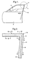
- FIG 1 shows a vehicle door 8 carrying a sealing and guiding channel arrangement 10 in which a pane of window glass 12 is slidable in a vertical direction as it is raised from or lowered into the lower part of -the door 8.
- the sealing and guiding arrangement 10 comprises a window frame and sealing and guiding channels mounted on the frame, as will be described.
- the sealing and guiding channels define a sharp corner 14 and the construction in the region of the sharp corner is shown in enlarged detail in Figure 2 .
- the sealing and guiding arrangement 10 comprises a strip portion 16.
- the strip portion 16 is of channel form to receive the window pane 12 and comprises an outer channel wall 16A (on the outside of the window pane) and an inner channel 16B (on the inside of the window pane).
- the sealing and guiding channel arrangement 10 comprises a strip portion 18.
- the strip portion 18 is of also channel form to receive the window pane 12 and comprises an outer channel wall 18A (that is, a channel wall on the outside of the window pane) and an inner channel wall 18B (that is, a channel wall on the inside of the window pane 12).
- the two strip portions 16 and 18 are mitre-cut and joined together at the sharp corner 14.
- the stiff window frame on which the strip portions 16,18 are mounted is only partly visible in Figures 1 and 2 .
- the construction of the window frame, and the manner in which the strip portions 16,18 are mounted on it will be described below.
- the window frame is smoothly radiussed as shown dotted at 19 and this part of the frame is covered over by a flap 20 forming part of the sealing and guiding channel 10 in a manner to be explained.
- the sealing and guiding strip channel 10 is produced, such as by extrusion, from flexible material such as plastics or rubber. It is designed to provide a weather-proof seal for the edge of the window glass and also to impose low friction on the movement of the glass.
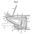
- Figure 3 shows a section on the line IV-IV of Figure 2 , that is, along the 'B' pillar.
- the stiff window frame is shown generally at 21 and comprises a rigid channel formed by bending over the outer panel 22 of the vehicle door and then forming the bent-over portion into channel form.
- the window frame 21 is completed by the inner panels 23 and 24 of the door which meet to form a flange 26.
- the strip portion 16 is made of extruded plastics or rubber material and is of integral channel-form comprising a base 28 and side walls 30 and 32.
- the side wall 30 extends in one direction to form a lip (a "cosmetic lip") 34 which covers over the edge of the flange 26 and extends in the other direction to form a longer and more flexible lip 36 which extends partway across the mouth of the channel.
- the distal edge of the wall 32 is extended to form a short flexible lip 38.
- Adjacent the base 28 of the channel is a further lip 40.
- the window pane 12 is guided within the channel as it slides in a vertical direction by the lips 36,38 and 40.
- the surfaces of these lips making contact with the window glass 12 are advantageously covered with layers of flock 42, or another suitable low-friction coating.
- the outside of the base 28 of the portion 16 has short outwardly extending lips 44,46 which help to secure the strip portion 16 within the channel of the window frame 21.
- Different parts of the strip portion 16 may have different hardnesses.
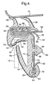
- FIG 4 is a cross-section on the line III-III of Figure 2 .
- the window frame shown generally at 50 is formed by panels 52,54 and 56 of the door which are joined together to form a flange 58 projecting outwardly of the door.
- the panels 52 and 54 diverge from each other in the direction away from the flange 58 to form a hollow space 60 and then come together again to form a further flange 62 where they are again joined together.
- the strip portion 18 is again extruded integrally from plastics or rubber material and defines a channel 64 which embraces the flange 58 to hold the strip portion 18 in position.
- the extruded material may carry integral inwardly extending lips 66 to assist in securing the sealing and guiding strip in position on the flange and a reinforcing carrier 67 may be embedded in the extruded material.
- the reinforcing carrier 67 may be formed from any suitable relatively rigid material, such as metal or plastics.
- the extruded material of the strip portion on one outside wall of the channel 64 carries large flexible sealing lips 68 which, when the vehicle door 8 is closed, seal against the roof line 70 of the vehicle.
- the material on the outside of the base of the channel 64 carries a re-entrant lip 72.
- the material adjacent the mouth of the channel 58 is extended to form a limb 74 which lies against the door panel 54 and terminates in a lip (a "cosmetic lip") 76 which embraces the edge of the flange 62.
- the distal end of the limb 74 integrally carries a large flexible lip 78 which extends towards the lip 72 so that, together, these lips define the channel for receiving the window pane 12 (shown dotted).
- a further lip 80 extends partway across the base of this channel.
- the surfaces of the lips 72,78 and 80 which make contact with the window pane 12 may carry layers of flock 42, or another suitable low-friction coating.
- the limb 74 is further clamped to the window frame by means of a resiliently deformable protrusion 82 having an enlarged head portion 84 which is pushed through an aperture 86 in the panel 54 and into the hollow space 60. After passing through the aperture 86, the enlarged head 84 resiles and presses against the panel 54 around the edges of the aperture 86.
- the extruded plastics or rubber material of the strip portion 16 of Figure 3 is provided with a longitudinally extending hollow cavity or chamber 90 located near the distal edge of the channel side wall 30.
- a similar longitudinally extending hollow chamber 90 is provided in the material of the strip portion 18 shown in Figure 4 , this hollow chamber being located at the distal end of the limb 74.
- the window frame 12 includes a portion 19 (shown dotted) which smoothly bridges across the sharp corner.
- the door panels 23,24 ( Figure 3 ) are progressively extended in length (in the direction towards the centre of the window opening), in the immediate vicinity of the sharp angle 14, this increase in length being progressively greater in the direction up the "B" pillar towards the sharp corner 16.
- the lengths of the door panels 52 and 54 ( Figure 4 ) progressively increase in the direction along the roof line towards the sharp corner 16.
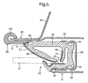
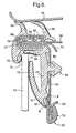
- Figure 5 shows a section on the line VI-VI of Figure 2 , the section plane being closer to the sharp corner 16 than the section plane IV-IV of Figure 3 .
- Figure 5 shows that the general-shape of the window frame and the strip portion 16 is similar to that shown in Figure 3 , except that the panels 22 and 24 have increased length.
- Figure 6 is a section on the line V-V of Figure 2 , the section plane being closer to the sharp angle 16 than the section plane III-III shown in Figure 4 .
- the configuration of the window frame and of the strip portion 18 is generally the same as is shown in Figure 4 , except for the extended lengths of the panels 52 and 54.
- this is achieved (for the strip portion 16) by cutting through the extruded material along the dotted line shown at 92 (in Figure 3 ) adjacent to the wall of the hollow chamber 90, so as to remove the cosmetic lip 34.
- a cut is made through the extruded material along the dotted line shown at 94 (in Figure 4 ) immediately adjacent the hollow chamber 90, so as to remove the cosmetic lip 76.
- cut may be made in a different position to that shown at 92 or 94.
- the two ends of the sealing and guiding strip portions 16,18 are brought together (after having been mitre-cut) in a mould.
- the moulding operation not only joins the mitre-cut ends together but also moulds the extended flap 20 (see Figures 5 and 6 ), carrying a cosmetic lip 102, into position on both strip portions 16,18.
- This flap 20 becomes joined to the sealing and guiding strip portions 16,18 along (only) regions A of the cutting lines 92 ( Figure 5 ) and 94 ( Figure 6 ).
- It is preferred in this embodiment to mould the flap 20 to the sealing and guiding strip portions 16,18 only along region A because this avoids having to subject the flock 42 in regions B to the heat and pressure required for the moulding operation. This reduces or prevents damage to the flock 42, so that the flock 42 will have a neat and attractive appearance, the flock extending completely up to the point where the flap 20 abuts the lip 78.
- the flap 20 it is possible to mould the flap 20 to the sealing and guiding strip portions 16,18 additionally (or alternatively) along regions B of the cutting lines 92 ( Figure 5 ) and 94 ( Figure 6 ). If, however, the flap 20 is moulded to the sealing and guiding strip portions 16,18 at regions B, then it may be advantageous to not apply flock 42 to the surface of the lip 78 near the region B, but instead to leave a non-flocked surface area between the flock 42 and the region B. Flock applied to this area may be damaged by the moulding process and might have an unattractive appearance, and there may not be a visually distinct line at the point where the flap 20 meets the lip 78.
- the cosmetic lip 102 carried by the moulded-on flap 20 embraces the flange produced where the ends of the extended panels 23,26 ( Fig. 5 ) meet and where the extended panels 52,54 ( Figure 6 ) meet.
- Figures 7 and 8 correspond generally to Figures 4 and 6 except that the window frame on which the strip portion 18 is mounted is not shown in Figures 7 and 8 . Parts in Figures 7 and 8 corresponding to parts in Figures 4 and 6 are similarly referenced.
- the hollow chamber 90 is not formed within the extruded material but is replaced by a hollow cavity 90A.
- the large flexible lip 78 has a "foot" 78A which is produced by the extrusion process so as to be separate from the extruded material of the cosmetic lip 76.
- Figure 9 shows the relative positioning of the distal edge of the foot 78A and the adjacent surface 76A of the cosmetic lip 76 at the exit of the extruder and shows a gap 'G' between them.
- a suitable roller arrangement is provided which forces the distal edge 78A of the foot 78 into firm contact with the surface 76A of the cosmetic lip 76.
- the two parts which are pressed firmly together by the roller arrangement become adhered to each other (for example, by the cross-linking process which continues after extrusion), thereby forming the cavity 90A. In this way, therefore, no unsightly gap is visible to an observer viewing into the channel which receives the window pane.
- the parts may be pressed together so that they abut one another but are not adhered together.
- FIG 8 the flap 20 is shown partially filling.the hollow cavity 90A. It should be understood that the material of the flap 20 could completely fill the hollow cavity 90A, so that there is no void.
- the region A where the flap 20 is moulded onto the material of the window channel is not externally visible, being hidden behind the distal edge of the foot 78A.
- the flap 20 may be only moulded onto the window channel at region A, or it may additionally (or alternatively) be moulded onto the window channel at region B, where the distal edge 78A of the foot 78 meets the flap 20.
- the flap 20 is made from TPE, instead of conventional EPDM.
- TPE can be formed and moulded onto other components at a lower mould temperature than is required for EPDM.
- the moulding process for the TPE flap is therefore less likely to damage the flock 42 at the distal edge 78A of the foot 78.
- the flap 20 could be formed of EPDM (or any other suitable material). If the flap 20 is formed of EPDM and is moulded onto the window channel at region B, then it may be preferred to not apply flock 42 to the distal edge 78A of the foot 78, because flock at this region may be damaged by the heat of the moulding operation and may have an unattractive appearance.
- TPE is also advantageous because it can be recycled relatively easily.
- the strip portion 16 ( Figures 3 and 5 ) may be modified in the same way as described with reference to Figures 7 , 8 and 9 , to produce a cavity 90A instead of the cavity or chamber 90.
- the moulding operation can thus be arranged to join the strip portions 16 and 18 together and to mould the extended flap 20, carrying the cosmetic lip 102, onto both strip portions where they meet at the corner of the window frame.
Landscapes
- Engineering & Computer Science (AREA)
- Mechanical Engineering (AREA)
- Seal Device For Vehicle (AREA)
Claims (27)
- Dichtungs- oder Führungs streifen (16), der einen aus flexiblem Material bestehenden Körper zum Anbringen an einer Platte (54) mit einer Kante (62) umfasst, wobei die Platte (54) steifer ist als das flexible Material und ihre Größe so variiert, dass die Platte einen ersten Bereich relativ geringer Ausdehnung und einen zweiten Bereich relativ großer Ausdehnung hat, wobei der Körper in Funktion den ersten Bereich der Platte (54) über deckt und in Funktion den zweiten Bereich der Platte (54) teilweise überdeckt und eine Kante mit einem Hohlraum (90), der in dem Körper nur an der Kante des Körpers angrenzend ausgebildet ist, sowie eine integrale Struktur (76) an der Kante des Körpers aufweist, dieso angeordnet ist, dass sie sich entlang das ersten Bereiches der Platte (54) direkt neben der Kante (62) der Platte (54) befindet, wobei die integrale Kanten struktur (76) an einem Bereich, der dem zweiten Bereich der Platte (54) entspricht, entlang einer Schnittlinie (92) entfernt werden kann, die sich in den Hohlraum (90) hin einer streckt, und wobei der Streifendes Weiteren einen separaten Kanten strukturteil (20) erweiterter Größe zum Ersetzen der integralen Kanten struktur (76) umfasst, wobei der separate Kanten strukturteil (20), wenn er an der Platte angebracht ist, an dem Körper entlang der Schnittlinie (92) befestigt ist, und sich in dem zweiten Bereich direkt neben der Kante (62) der Platte (54) befindet und die Platte (54) überdeckt.
- Streifen (16) nach Anspruch 1, wobei der Körper mit einem Extrusions prozess erzeugt wird, der auch die hohle Kammer erzeugt.
- Streifen (16) nach Anspruch 1, wobei der Körper unter Einsatz eines Extrusions prozesses erzeugt wird und der Hohlraum (90) erzeugt wird, in dem zwei Teile des Materials unmittelbar nach dem Extrusions prozess so zusammen gepresst werden, dass sie während der anschließenden Bearbeitung aneinander befestigt werden, jedoch der Hohlraum (90) zwischen ihnen verbleibt.
- Streifen (16) nach einem der vorangehenden Ansprüche, wobei sich die Größe der Platte in dem zweiten Bereich zunehmend ändert und sich die Größe der separaten Kanten struktur entsprechend ändert.
- Streifen (16) nach einem der vorangehenden Ansprüche, wobei die separate Kanten struktur mit einem Form vorgang erzeugt wird.
- Streifen (16) nach Anspruch 5, wobei der Formvorgang die separate Kanten struktur an dem Streifen (16) befestigt.
- Streifen (16) nach einem der vorangehenden Ansprüche, wobei sich der Hohlraum (90) über die gesamte Länge des Streifens (16) erstreckt.
- Streifen (16) nach einem der vorangehen den Ansprüche, der an einem zweiten Streifen (18) befestigt ist.
- Streifen (16) nach Anspruch 8, der mit einem Form vorgang an dem zweiten Streifen (18) befestigt wird.
- Streifen(16)nachAnspruch9,wobeiderFormvorgang,derihnandemzweiten Streifen (18) befestigt, auch die separate Kanten struktur (20) befestigt.
- Streifen (16) nach einem der vorangehenden Ansprüche, wobei die Kanten struktur (20) TPE umfasst.
- Streifen (16) nach einem der vorangehenden Ansprüche, der so geformt ist, dass er eine Rinne zum Aufnehmen einer Scheibe aus Fenster glas (12) für eine Fensteröffnung bildet, wobei die Platte Teil eines starren Rahmens (21) für die Fensteröffnung ist.
- Streifen (16) nach einem der Ansprüche 1 bis 11, der eine Rinne zum Aufnehmen einer Scheibe aus Fenster glas (12) für eine vorgegebene Fensteröffnung bildet, wobei die Platte einen Teil eines Rahmens (21) für die Fenster öffnung bildet und der zweite Bereich ein Bereich ist, der an eine Richtungsänderung des Fensterrahmens (21) angrenzt.
- Streifen (16) nach Anspruch 13 in Kombination mit einem zweiten Streifen (18), der auch eine Rinne zum Aufnehmender Scheibe aus Fenster glas (12) bildet, wobei die zwei Streifen (18) an der Richtungsänderung des Fensterrahmens (21) an einander befestigt sind.
- Streifen (16) nach Anspruch 14, wobei die separate Kanten struktur (20) auch an dem zweiten Streifen (18) befestigt ist.
- Fensterrahmen anordnung für eine Fensteröffnung, die einen steifen Fensterrahmen (21) mit einem gleichmäßigger undeten Bereich (19), der über eine Richtungsänderung der Fensteröffnung verläuft, und zwei Dichtungs- oder Führungs streifen (16, 18) nach einem der Ansprüche 1 bis 11 umfasst, wobei die Platte (54) Teil des Rahmens (21) ist, der gleichmäßigger undete Bereich (19) des Rahmens (21) dem zweiten Be-reich relativ großer Ausdehnung der Platte (54) entspricht, jeder streifen (16, 18) eine Rinne zum Aufnehmen einer Scheibe aus Fenster glas (12) für die Öffnung bildet und sie an der Richtungs änderung an einander befestigt sind, wobei die Kanten struktur (76) jedes Streifens (16, 18) so eingerichtet ist, dass sie mit einer Kante des Fensterrahmens(21)entlangeinesAbschnittsderLängedesstreifens(16,18) außerhalb des gleichmäßigger undeten Bereichs (19) des Rahmens (21) und an dem ersten Bereich relativ geringer Ausdehnung der Platte (54) und der separate Kanten- strukturteil (20) mit einer Kante des Fensterrahmens (21) in dem gleichmäßigger undeten Bereich (19) des Rahmens (21) und an dem zweiten Bereich relativ großer Ausdehnung der Platte (54) in Eingriff kommt.
- Anordnung nach Anspruch 16, wobei der separate Kanten strukturteil (20) an den Streifen (16, 18) jeweils entlang ihrer Schnittlinien (92, 94) befestigt ist.
- Anordnung nach Anspruch 16 oder 17, wobei die Integrale Kanten struktur und der separate Kanten strukturteil (20) jeweils so geformt sind, dass sie eine kosmetische Lippe (34, 76) bilden.
- Anordnung nach einem der Ansprüche 16 bis 18, wobei die Richtungsänderung der Fensteröffnung eine scharte Ecke des Fensterrahmens (21) ist.
- Verfahren zum Herstellen eines Dichtungs- oder Führungs streifens (16), wobei das Verfahren Ausbilden eines aus flexiblem Material bestehenden Körpers zum Anbringen an einer Platte (54) mit einer Kante (62) einschließt, die Platte (54) starrer ist als das flexible Material und ihre Größes ovarilert, dass die Platte einen ersten Bereich relativ geringer Ausdehnung und einen zweiten Bereich relativer großer Ausdehnung hat, wobei der Körper in Funktion den ersten Bereich der Platte (54) überdeckt und in Funktion den zweiten Bereich der Platte (54) teilweise über deckt, der Körper eine Kante mit einem Hohlraum (90), der in dem Körpernurandle Kante des Körpers angrenzend ausgebildet ist, sowie eine integrale Struktur (76) aufweist, die an der Kante des Körpers ausgebildet und so angeordnet ist, dass sie sich entlang das ersten Bereichs der Platte (54) direkt neben der Kante (62) der Platte (54) befindet, dadurch gekennzeichnet, dass die integrale Kanten struktur (76) an einem Bereich, der dem zweiten Bereich der Platte entspricht, entlang einer Schnittlinie (92) entfernt wird, die sich in den Hohlraum (90) hin einer streckt, und durch einen separaten Kanten strukturteil (20) erweiterter Größer ersetzt wird, der an dem Körper entlang der Schnittlinie (92) befestigt wird und sich in dem zweiten Bereich direkt neben der Kante (62) der Platte (54) befindet und die Platte (54) in dem zweiten Bereich über deckt.
- Verfahren nach Anspruch 20, wobei der Körper mit einem Extrusions prozess erzeugt wird der auch die hohle Kammer erzeugt.
- Verfahren nach Anspruch 20, wobei der Körper unter Verwendung eines Extrusions- prozesses erzeugt wird, und der Hohlraum (90) erzeugt wird, in dem zwei Teile des Materials unmittelbar nach dem Extrusions prozess so zusammen gepresst werden, dass sie während der anschließenden Bearbeitung an einander befestigt werden, jedoch der Hohlraum (90) zwischen ihnen verbleibt.
- VerfahrennachdenAnsprüchen20,21oder22,wobeidieseparateKantenstruktur mit einen Form vorgang erzeugt wird.
- Verfahren nach Anspruch 23, wobei der Formvorgang die separate Kanten struktur an dem Streifen (16) befestigt.
- Verfahren nach einem der Ansprüche 20, 21, 22, 23 oder 24, das das Befestigen des Streifens (16) an einem zweiten Streifen (18) einschließt.
- Verfahren nach Anspruch 25, das das Befestig endes Streifens (16) an dem zweiten Streifen (18) mit einem Form vorgang einschließt.
- Verfahren nach Anspruch 26, wobei der Form vorgang, der in an dem zweiten Streifen (18) befestigt, auch die separate Kanten struktur (20) befestigt.
Applications Claiming Priority (5)
| Application Number | Priority Date | Filing Date | Title |
|---|---|---|---|
| GB0228290 | 2002-12-04 | ||
| GB0228290A GB0228290D0 (en) | 2002-12-04 | 2002-12-04 | Window sealing and guiding arrangements |
| GB0230327A GB0230327D0 (en) | 2002-12-04 | 2002-12-31 | Window sealing and guiding arrangements |
| GB0230327 | 2002-12-31 | ||
| PCT/IB2003/005622 WO2004050408A1 (en) | 2002-12-04 | 2003-12-01 | Window sealing and guiding arrangements |
Publications (3)
| Publication Number | Publication Date |
|---|---|
| EP1567382A1 EP1567382A1 (de) | 2005-08-31 |
| EP1567382B1 true EP1567382B1 (de) | 2008-06-25 |
| EP1567382B8 EP1567382B8 (de) | 2008-08-13 |
Family
ID=32472156
Family Applications (1)
| Application Number | Title | Priority Date | Filing Date |
|---|---|---|---|
| EP03812241A Expired - Lifetime EP1567382B8 (de) | 2002-12-04 | 2003-12-01 | Fensterdichtungs- und führungsanordnungen |
Country Status (4)
| Country | Link |
|---|---|
| US (1) | US20060150522A1 (de) |
| EP (1) | EP1567382B8 (de) |
| AU (1) | AU2003302632A1 (de) |
| WO (1) | WO2004050408A1 (de) |
Families Citing this family (15)
| Publication number | Priority date | Publication date | Assignee | Title |
|---|---|---|---|---|
| GB0423875D0 (en) | 2004-10-27 | 2004-12-01 | Gdx North America Inc | Sealing or guiding assemblies and methods of making them |
| EP1805051B1 (de) * | 2004-10-27 | 2013-11-20 | Henniges Automotive Sealing Systems North America, Inc. | Dichtungs- oder führungsanordnung und herstellungsverfahren dafür |
| ES1059026Y (es) * | 2004-11-29 | 2005-06-16 | Seat Sa | Guia para cristales elevables de ventanillas de puertas de vehiculos. |
| DE602006013288D1 (de) * | 2005-04-04 | 2010-05-12 | Henniges Automotive Sealing Sy | Dichtungs- oder führungsanordnungen für fenster und montageverfahren |
| GB2429027A (en) * | 2005-08-12 | 2007-02-14 | Gdx North America Inc | Window sealing and guiding arrangements |
| DE102006060390B3 (de) * | 2006-12-20 | 2008-02-07 | Metzeler Automotive Profile Systems Gmbh | Dichtungsprofil, insbesondere zum Abdichten einer Tür gegenüber der Karosserie eines Kraftfahrzeugs |
| DE102008060288B4 (de) | 2008-12-03 | 2011-05-12 | Csa Germany Gmbh & Co. Kg | Dichtungsprofil |
| US8631609B2 (en) * | 2009-04-16 | 2014-01-21 | Cooper-Standard Automotive Inc. | Integral trim to seal off weatherstrip and remove need for foam pads |
| JP6123524B2 (ja) * | 2013-07-02 | 2017-05-10 | スズキ株式会社 | ドア構造 |
| US9290083B2 (en) * | 2013-12-18 | 2016-03-22 | Ford Global Technologies, Llc | Glass sealing system |
| DE102016117957A1 (de) * | 2016-09-23 | 2018-03-29 | Cooper Standard GmbH | Dichtungsanordnung für ein Kraftfahrzeugfenster, Dichtungsverbund und Verfahren zum Herstellen eines Dichtungsverbundes |
| US11691490B2 (en) | 2017-05-11 | 2023-07-04 | Henniges Automotive Sealing Systems North America, Inc. | Seal assembly |
| JP6960346B2 (ja) * | 2018-02-06 | 2021-11-05 | 日産自動車株式会社 | 自動車用ドアウエザーストリップ |
| WO2022245897A1 (en) * | 2021-05-18 | 2022-11-24 | Henniges Automotive Sealing Systems North America, Inc. | Sealing profile for a flushed window |
| CN216580061U (zh) | 2022-01-14 | 2022-05-24 | 瀚德(中国)汽车密封系统有限公司 | 一种零阶差车门结构及车门 |
Family Cites Families (12)
| Publication number | Priority date | Publication date | Assignee | Title |
|---|---|---|---|---|
| GB1431460A (en) * | 1973-07-12 | 1976-04-07 | Schlegel Uk Ltd | Method of forming corners in elastomeric cellular strip |
| DE3616661A1 (de) * | 1986-05-16 | 1987-11-26 | Audi Ag | Dichtung |
| US5042201A (en) * | 1990-01-18 | 1991-08-27 | The Standard Products Company | One-piece weatherstrip with constant cross-section at corner bends |
| US4949507A (en) * | 1990-01-18 | 1990-08-21 | The Standard Products Company | One-piece expandable weatherstrip |
| US5269101A (en) * | 1991-07-29 | 1993-12-14 | Toyoda Gosei Co., Ltd. | Automotive weatherstrip |
| GB2285471B (en) * | 1994-01-11 | 1997-02-12 | Draftex Ind Ltd | Sealing or guiding assemblies and methods of making them |
| US6023888A (en) * | 1996-09-25 | 2000-02-15 | Schlegel Corporation | Door and window channel seal |
| GB2321268B (en) * | 1997-01-17 | 2000-06-21 | Draftex Ind Ltd | Sealing or guiding assemblies and methods of making them |
| GB2353553B (en) * | 1999-08-27 | 2003-05-21 | Draftex Ind Ltd | Sealing and guiding strips |
| JP2001233060A (ja) * | 2000-02-21 | 2001-08-28 | Toyoda Gosei Co Ltd | 自動車用ドアにおけるトリム及びガラスランの取付構造 |
| JP3885470B2 (ja) * | 2000-08-23 | 2007-02-21 | 豊田合成株式会社 | 車両用ガラスランおよびその製造方法 |
| DE60202108T2 (de) * | 2001-09-14 | 2005-12-01 | Toyoda Gosei Co., Ltd. | Dichtung für ein Fahrzeug |
-
2003
- 2003-12-01 US US10/537,502 patent/US20060150522A1/en not_active Abandoned
- 2003-12-01 WO PCT/IB2003/005622 patent/WO2004050408A1/en not_active Ceased
- 2003-12-01 EP EP03812241A patent/EP1567382B8/de not_active Expired - Lifetime
- 2003-12-01 AU AU2003302632A patent/AU2003302632A1/en not_active Abandoned
Also Published As
| Publication number | Publication date |
|---|---|
| US20060150522A1 (en) | 2006-07-13 |
| EP1567382A1 (de) | 2005-08-31 |
| WO2004050408A1 (en) | 2004-06-17 |
| AU2003302632A1 (en) | 2004-06-23 |
| EP1567382B8 (de) | 2008-08-13 |
Similar Documents
| Publication | Publication Date | Title |
|---|---|---|
| EP0628439B1 (de) | Dichtungsstreifen für bewegbares Kraftfahrzeugfenster | |
| EP1567382B1 (de) | Fensterdichtungs- und führungsanordnungen | |
| US8479449B2 (en) | Sealing, trimming and guiding strip | |
| US6996936B1 (en) | Sealing and guiding strip for a window with insert for corner of the window frame | |
| US8782954B2 (en) | Glass run | |
| US5136773A (en) | Method of forming a shaped section for guiding and sealing a movable window | |
| JP4344809B2 (ja) | ドアウエザストリップ | |
| US20090071077A1 (en) | Automotive glass run | |
| GB2285471A (en) | Sealing or guiding strip | |
| US12263722B2 (en) | Glass run and method of manufacturing the same | |
| US20100001550A1 (en) | Sealing or guiding assemblies and methods of making them | |
| EP0605092B1 (de) | Dichtungs- oder leistenförmiger Streifen, Fensterrahmenvorrichtung und Verfahren zur Herstellung | |
| US20070194539A1 (en) | Sealing, trimming or guiding strips | |
| JP2004123007A (ja) | 自動車のドアシール構造 | |
| EP1843910B1 (de) | Dichtung oder führungseinrichtung und verfahren zur dessen herstellung | |
| EP0799735A1 (de) | Dichtungs-und Führungsleisten | |
| JP2007161200A (ja) | 自動車用ガラスラン | |
| GB2429027A (en) | Window sealing and guiding arrangements | |
| JP2005329728A (ja) | 自動車用ガラスラン | |
| CN1745000A (zh) | 窗密封和导向结构 | |
| GB2426275A (en) | Sealing or guiding assembly for a closure member eg window | |
| JPH06286531A (ja) | 自動車用ウェザーストリップ | |
| JP2006151059A (ja) | 自動車用ガラスラン | |
| JPH04353016A (ja) | 車両用ウインドモールディングの製造方法 | |
| JP2006335079A (ja) | 自動車用ガラスラン及びその製造方法 |
Legal Events
| Date | Code | Title | Description |
|---|---|---|---|
| PUAI | Public reference made under article 153(3) epc to a published international application that has entered the european phase |
Free format text: ORIGINAL CODE: 0009012 |
|
| 17P | Request for examination filed |
Effective date: 20050608 |
|
| AK | Designated contracting states |
Kind code of ref document: A1 Designated state(s): AT BE BG CH CY CZ DE DK EE ES FI FR GB GR HU IE IT LI LU MC NL PT RO SE SI SK TR |
|
| AX | Request for extension of the european patent |
Extension state: AL LT LV MK |
|
| DAX | Request for extension of the european patent (deleted) | ||
| 17Q | First examination report despatched |
Effective date: 20050914 |
|
| GRAP | Despatch of communication of intention to grant a patent |
Free format text: ORIGINAL CODE: EPIDOSNIGR1 |
|
| GRAS | Grant fee paid |
Free format text: ORIGINAL CODE: EPIDOSNIGR3 |
|
| GRAA | (expected) grant |
Free format text: ORIGINAL CODE: 0009210 |
|
| AK | Designated contracting states |
Kind code of ref document: B1 Designated state(s): AT BE BG CH CY CZ DE DK EE ES FI FR GB GR HU IE IT LI LU MC NL PT RO SE SI SK TR |
|
| REG | Reference to a national code |
Ref country code: GB Ref legal event code: FG4D |
|
| RAP2 | Party data changed (patent owner data changed or rights of a patent transferred) |
Owner name: HENNIGES AUTOMOTIVE SEALING SYSTEMS NORTH AMERICA, |
|
| REG | Reference to a national code |
Ref country code: CH Ref legal event code: EP |
|
| REF | Corresponds to: |
Ref document number: 60321815 Country of ref document: DE Date of ref document: 20080807 Kind code of ref document: P |
|
| REG | Reference to a national code |
Ref country code: IE Ref legal event code: FG4D |
|
| NLT2 | Nl: modifications (of names), taken from the european patent patent bulletin |
Owner name: HENNIGES AUTOMOTIVE SEALING SYSTEMS Effective date: 20080730 |
|
| PG25 | Lapsed in a contracting state [announced via postgrant information from national office to epo] |
Ref country code: FI Free format text: LAPSE BECAUSE OF FAILURE TO SUBMIT A TRANSLATION OF THE DESCRIPTION OR TO PAY THE FEE WITHIN THE PRESCRIBED TIME-LIMIT Effective date: 20080625 Ref country code: SI Free format text: LAPSE BECAUSE OF FAILURE TO SUBMIT A TRANSLATION OF THE DESCRIPTION OR TO PAY THE FEE WITHIN THE PRESCRIBED TIME-LIMIT Effective date: 20080625 |
|
| PG25 | Lapsed in a contracting state [announced via postgrant information from national office to epo] |
Ref country code: AT Free format text: LAPSE BECAUSE OF FAILURE TO SUBMIT A TRANSLATION OF THE DESCRIPTION OR TO PAY THE FEE WITHIN THE PRESCRIBED TIME-LIMIT Effective date: 20080625 Ref country code: NL Free format text: LAPSE BECAUSE OF FAILURE TO SUBMIT A TRANSLATION OF THE DESCRIPTION OR TO PAY THE FEE WITHIN THE PRESCRIBED TIME-LIMIT Effective date: 20080625 |
|
| NLV1 | Nl: lapsed or annulled due to failure to fulfill the requirements of art. 29p and 29m of the patents act | ||
| PG25 | Lapsed in a contracting state [announced via postgrant information from national office to epo] |
Ref country code: PT Free format text: LAPSE BECAUSE OF FAILURE TO SUBMIT A TRANSLATION OF THE DESCRIPTION OR TO PAY THE FEE WITHIN THE PRESCRIBED TIME-LIMIT Effective date: 20081125 Ref country code: SE Free format text: LAPSE BECAUSE OF FAILURE TO SUBMIT A TRANSLATION OF THE DESCRIPTION OR TO PAY THE FEE WITHIN THE PRESCRIBED TIME-LIMIT Effective date: 20080925 Ref country code: CZ Free format text: LAPSE BECAUSE OF FAILURE TO SUBMIT A TRANSLATION OF THE DESCRIPTION OR TO PAY THE FEE WITHIN THE PRESCRIBED TIME-LIMIT Effective date: 20080625 Ref country code: ES Free format text: LAPSE BECAUSE OF FAILURE TO SUBMIT A TRANSLATION OF THE DESCRIPTION OR TO PAY THE FEE WITHIN THE PRESCRIBED TIME-LIMIT Effective date: 20081006 |
|
| PG25 | Lapsed in a contracting state [announced via postgrant information from national office to epo] |
Ref country code: RO Free format text: LAPSE BECAUSE OF FAILURE TO SUBMIT A TRANSLATION OF THE DESCRIPTION OR TO PAY THE FEE WITHIN THE PRESCRIBED TIME-LIMIT Effective date: 20080625 Ref country code: BE Free format text: LAPSE BECAUSE OF FAILURE TO SUBMIT A TRANSLATION OF THE DESCRIPTION OR TO PAY THE FEE WITHIN THE PRESCRIBED TIME-LIMIT Effective date: 20080625 Ref country code: SK Free format text: LAPSE BECAUSE OF FAILURE TO SUBMIT A TRANSLATION OF THE DESCRIPTION OR TO PAY THE FEE WITHIN THE PRESCRIBED TIME-LIMIT Effective date: 20080625 |
|
| PG25 | Lapsed in a contracting state [announced via postgrant information from national office to epo] |
Ref country code: EE Free format text: LAPSE BECAUSE OF FAILURE TO SUBMIT A TRANSLATION OF THE DESCRIPTION OR TO PAY THE FEE WITHIN THE PRESCRIBED TIME-LIMIT Effective date: 20080625 Ref country code: DK Free format text: LAPSE BECAUSE OF FAILURE TO SUBMIT A TRANSLATION OF THE DESCRIPTION OR TO PAY THE FEE WITHIN THE PRESCRIBED TIME-LIMIT Effective date: 20080625 Ref country code: BG Free format text: LAPSE BECAUSE OF FAILURE TO SUBMIT A TRANSLATION OF THE DESCRIPTION OR TO PAY THE FEE WITHIN THE PRESCRIBED TIME-LIMIT Effective date: 20080925 |
|
| PLBE | No opposition filed within time limit |
Free format text: ORIGINAL CODE: 0009261 |
|
| STAA | Information on the status of an ep patent application or granted ep patent |
Free format text: STATUS: NO OPPOSITION FILED WITHIN TIME LIMIT |
|
| 26N | No opposition filed |
Effective date: 20090326 |
|
| PG25 | Lapsed in a contracting state [announced via postgrant information from national office to epo] |
Ref country code: MC Free format text: LAPSE BECAUSE OF NON-PAYMENT OF DUE FEES Effective date: 20081231 |
|
| REG | Reference to a national code |
Ref country code: CH Ref legal event code: PL |
|
| GBPC | Gb: european patent ceased through non-payment of renewal fee |
Effective date: 20081201 |
|
| PG25 | Lapsed in a contracting state [announced via postgrant information from national office to epo] |
Ref country code: IT Free format text: LAPSE BECAUSE OF FAILURE TO SUBMIT A TRANSLATION OF THE DESCRIPTION OR TO PAY THE FEE WITHIN THE PRESCRIBED TIME-LIMIT Effective date: 20080625 |
|
| REG | Reference to a national code |
Ref country code: IE Ref legal event code: MM4A |
|
| REG | Reference to a national code |
Ref country code: FR Ref legal event code: ST Effective date: 20090831 |
|
| PG25 | Lapsed in a contracting state [announced via postgrant information from national office to epo] |
Ref country code: CH Free format text: LAPSE BECAUSE OF NON-PAYMENT OF DUE FEES Effective date: 20081231 Ref country code: LI Free format text: LAPSE BECAUSE OF NON-PAYMENT OF DUE FEES Effective date: 20081231 Ref country code: IE Free format text: LAPSE BECAUSE OF NON-PAYMENT OF DUE FEES Effective date: 20081201 |
|
| PG25 | Lapsed in a contracting state [announced via postgrant information from national office to epo] |
Ref country code: GB Free format text: LAPSE BECAUSE OF NON-PAYMENT OF DUE FEES Effective date: 20081201 |
|
| PG25 | Lapsed in a contracting state [announced via postgrant information from national office to epo] |
Ref country code: FR Free format text: LAPSE BECAUSE OF NON-PAYMENT OF DUE FEES Effective date: 20081231 |
|
| PG25 | Lapsed in a contracting state [announced via postgrant information from national office to epo] |
Ref country code: HU Free format text: LAPSE BECAUSE OF FAILURE TO SUBMIT A TRANSLATION OF THE DESCRIPTION OR TO PAY THE FEE WITHIN THE PRESCRIBED TIME-LIMIT Effective date: 20081226 Ref country code: CY Free format text: LAPSE BECAUSE OF FAILURE TO SUBMIT A TRANSLATION OF THE DESCRIPTION OR TO PAY THE FEE WITHIN THE PRESCRIBED TIME-LIMIT Effective date: 20080625 Ref country code: LU Free format text: LAPSE BECAUSE OF NON-PAYMENT OF DUE FEES Effective date: 20081201 |
|
| PG25 | Lapsed in a contracting state [announced via postgrant information from national office to epo] |
Ref country code: TR Free format text: LAPSE BECAUSE OF FAILURE TO SUBMIT A TRANSLATION OF THE DESCRIPTION OR TO PAY THE FEE WITHIN THE PRESCRIBED TIME-LIMIT Effective date: 20080625 |
|
| PG25 | Lapsed in a contracting state [announced via postgrant information from national office to epo] |
Ref country code: GR Free format text: LAPSE BECAUSE OF FAILURE TO SUBMIT A TRANSLATION OF THE DESCRIPTION OR TO PAY THE FEE WITHIN THE PRESCRIBED TIME-LIMIT Effective date: 20080926 |
|
| PGFP | Annual fee paid to national office [announced via postgrant information from national office to epo] |
Ref country code: DE Payment date: 20171129 Year of fee payment: 15 |
|
| REG | Reference to a national code |
Ref country code: DE Ref legal event code: R119 Ref document number: 60321815 Country of ref document: DE |
|
| PG25 | Lapsed in a contracting state [announced via postgrant information from national office to epo] |
Ref country code: DE Free format text: LAPSE BECAUSE OF NON-PAYMENT OF DUE FEES Effective date: 20190702 |