EP1567382B1 - Window sealing and guiding arrangements - Google Patents
Window sealing and guiding arrangements Download PDFInfo
- Publication number
- EP1567382B1 EP1567382B1 EP03812241A EP03812241A EP1567382B1 EP 1567382 B1 EP1567382 B1 EP 1567382B1 EP 03812241 A EP03812241 A EP 03812241A EP 03812241 A EP03812241 A EP 03812241A EP 1567382 B1 EP1567382 B1 EP 1567382B1
- Authority
- EP
- European Patent Office
- Prior art keywords
- strip
- region
- panel
- edge
- edge formation
- Prior art date
- Legal status (The legal status is an assumption and is not a legal conclusion. Google has not performed a legal analysis and makes no representation as to the accuracy of the status listed.)
- Expired - Lifetime
Links
- 238000007789 sealing Methods 0.000 title claims description 30
- 239000000463 material Substances 0.000 claims description 27
- 238000000034 method Methods 0.000 claims description 19
- 239000002537 cosmetic Substances 0.000 claims description 15
- 238000000465 moulding Methods 0.000 claims description 15
- 238000001125 extrusion Methods 0.000 claims description 9
- 239000005357 flat glass Substances 0.000 claims description 7
- 238000004519 manufacturing process Methods 0.000 claims description 3
- 238000003825 pressing Methods 0.000 claims description 3
- 230000015572 biosynthetic process Effects 0.000 claims 22
- 244000144992 flock Species 0.000 description 11
- 229920002943 EPDM rubber Polymers 0.000 description 4
- 238000010276 construction Methods 0.000 description 4
- 238000005520 cutting process Methods 0.000 description 4
- 229920001971 elastomer Polymers 0.000 description 4
- 239000004033 plastic Substances 0.000 description 3
- 229920003023 plastic Polymers 0.000 description 3
- 239000011248 coating agent Substances 0.000 description 2
- 238000000576 coating method Methods 0.000 description 2
- 239000003000 extruded plastic Substances 0.000 description 2
- 239000011796 hollow space material Substances 0.000 description 2
- 230000003014 reinforcing effect Effects 0.000 description 2
- 238000005452 bending Methods 0.000 description 1
- 238000004132 cross linking Methods 0.000 description 1
- 230000002939 deleterious effect Effects 0.000 description 1
- 230000001419 dependent effect Effects 0.000 description 1
- 239000011521 glass Substances 0.000 description 1
- 235000019589 hardness Nutrition 0.000 description 1
- 239000002184 metal Substances 0.000 description 1
- 230000004048 modification Effects 0.000 description 1
- 238000012986 modification Methods 0.000 description 1
- 239000011800 void material Substances 0.000 description 1
Images


Classifications
-
- B—PERFORMING OPERATIONS; TRANSPORTING
- B60—VEHICLES IN GENERAL
- B60J—WINDOWS, WINDSCREENS, NON-FIXED ROOFS, DOORS, OR SIMILAR DEVICES FOR VEHICLES; REMOVABLE EXTERNAL PROTECTIVE COVERINGS SPECIALLY ADAPTED FOR VEHICLES
- B60J10/00—Sealing arrangements
- B60J10/30—Sealing arrangements characterised by the fastening means
- B60J10/32—Sealing arrangements characterised by the fastening means using integral U-shaped retainers
-
- B—PERFORMING OPERATIONS; TRANSPORTING
- B60—VEHICLES IN GENERAL
- B60J—WINDOWS, WINDSCREENS, NON-FIXED ROOFS, DOORS, OR SIMILAR DEVICES FOR VEHICLES; REMOVABLE EXTERNAL PROTECTIVE COVERINGS SPECIALLY ADAPTED FOR VEHICLES
- B60J10/00—Sealing arrangements
- B60J10/20—Sealing arrangements characterised by the shape
- B60J10/21—Sealing arrangements characterised by the shape having corner parts or bends
Definitions
- the invention relates to window sealing and guiding arrangements.
- Embodiments of the invention to be described in more detail below by way of example only, are in the form of sealing and guiding strips and window frame arrangements for window frames carried by vehicle doors, where the window frame has a change in direction.
- embodiments of the invention can be used for other purposes.
- US-A-5269101 , EP-A-0245594 and GB-A-1431460 disclose sealing strips for mounting on a rigid panel, such as a door frame, in a region where there is a change in direction of that panel (for example at the corner of a door frame).
- document WO 01/15926 is considered to be the most relevant prior art document.
- additional components were introduced into the sealing strip in the region of the change in direction in order to allow the strip to satisfactorily follow the change in direction. The joins between these additional components and the strip are visible in use, which has a deleterious effect on the appearance of the sealing strip as a whole.
- the invention also provides a window frame arrangement in combination with the strip, as defined in claim 16.
- the invention further provides a method of making a strip as defined in claim 20.
- FIG 1 shows a vehicle door 8 carrying a sealing and guiding channel arrangement 10 in which a pane of window glass 12 is slidable in a vertical direction as it is raised from or lowered into the lower part of -the door 8.
- the sealing and guiding arrangement 10 comprises a window frame and sealing and guiding channels mounted on the frame, as will be described.
- the sealing and guiding channels define a sharp corner 14 and the construction in the region of the sharp corner is shown in enlarged detail in Figure 2 .
- the sealing and guiding arrangement 10 comprises a strip portion 16.
- the strip portion 16 is of channel form to receive the window pane 12 and comprises an outer channel wall 16A (on the outside of the window pane) and an inner channel 16B (on the inside of the window pane).
- the sealing and guiding channel arrangement 10 comprises a strip portion 18.
- the strip portion 18 is of also channel form to receive the window pane 12 and comprises an outer channel wall 18A (that is, a channel wall on the outside of the window pane) and an inner channel wall 18B (that is, a channel wall on the inside of the window pane 12).
- the two strip portions 16 and 18 are mitre-cut and joined together at the sharp corner 14.
- the stiff window frame on which the strip portions 16,18 are mounted is only partly visible in Figures 1 and 2 .
- the construction of the window frame, and the manner in which the strip portions 16,18 are mounted on it will be described below.
- the window frame is smoothly radiussed as shown dotted at 19 and this part of the frame is covered over by a flap 20 forming part of the sealing and guiding channel 10 in a manner to be explained.
- the sealing and guiding strip channel 10 is produced, such as by extrusion, from flexible material such as plastics or rubber. It is designed to provide a weather-proof seal for the edge of the window glass and also to impose low friction on the movement of the glass.
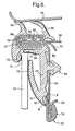
- Figure 3 shows a section on the line IV-IV of Figure 2 , that is, along the 'B' pillar.
- the stiff window frame is shown generally at 21 and comprises a rigid channel formed by bending over the outer panel 22 of the vehicle door and then forming the bent-over portion into channel form.
- the window frame 21 is completed by the inner panels 23 and 24 of the door which meet to form a flange 26.
- the strip portion 16 is made of extruded plastics or rubber material and is of integral channel-form comprising a base 28 and side walls 30 and 32.
- the side wall 30 extends in one direction to form a lip (a "cosmetic lip") 34 which covers over the edge of the flange 26 and extends in the other direction to form a longer and more flexible lip 36 which extends partway across the mouth of the channel.
- the distal edge of the wall 32 is extended to form a short flexible lip 38.
- Adjacent the base 28 of the channel is a further lip 40.
- the window pane 12 is guided within the channel as it slides in a vertical direction by the lips 36,38 and 40.
- the surfaces of these lips making contact with the window glass 12 are advantageously covered with layers of flock 42, or another suitable low-friction coating.
- the outside of the base 28 of the portion 16 has short outwardly extending lips 44,46 which help to secure the strip portion 16 within the channel of the window frame 21.
- Different parts of the strip portion 16 may have different hardnesses.
- FIG 4 is a cross-section on the line III-III of Figure 2 .
- the window frame shown generally at 50 is formed by panels 52,54 and 56 of the door which are joined together to form a flange 58 projecting outwardly of the door.
- the panels 52 and 54 diverge from each other in the direction away from the flange 58 to form a hollow space 60 and then come together again to form a further flange 62 where they are again joined together.
- the strip portion 18 is again extruded integrally from plastics or rubber material and defines a channel 64 which embraces the flange 58 to hold the strip portion 18 in position.
- the extruded material may carry integral inwardly extending lips 66 to assist in securing the sealing and guiding strip in position on the flange and a reinforcing carrier 67 may be embedded in the extruded material.
- the reinforcing carrier 67 may be formed from any suitable relatively rigid material, such as metal or plastics.
- the extruded material of the strip portion on one outside wall of the channel 64 carries large flexible sealing lips 68 which, when the vehicle door 8 is closed, seal against the roof line 70 of the vehicle.
- the material on the outside of the base of the channel 64 carries a re-entrant lip 72.
- the material adjacent the mouth of the channel 58 is extended to form a limb 74 which lies against the door panel 54 and terminates in a lip (a "cosmetic lip") 76 which embraces the edge of the flange 62.
- the distal end of the limb 74 integrally carries a large flexible lip 78 which extends towards the lip 72 so that, together, these lips define the channel for receiving the window pane 12 (shown dotted).
- a further lip 80 extends partway across the base of this channel.
- the surfaces of the lips 72,78 and 80 which make contact with the window pane 12 may carry layers of flock 42, or another suitable low-friction coating.
- the limb 74 is further clamped to the window frame by means of a resiliently deformable protrusion 82 having an enlarged head portion 84 which is pushed through an aperture 86 in the panel 54 and into the hollow space 60. After passing through the aperture 86, the enlarged head 84 resiles and presses against the panel 54 around the edges of the aperture 86.
- the extruded plastics or rubber material of the strip portion 16 of Figure 3 is provided with a longitudinally extending hollow cavity or chamber 90 located near the distal edge of the channel side wall 30.
- a similar longitudinally extending hollow chamber 90 is provided in the material of the strip portion 18 shown in Figure 4 , this hollow chamber being located at the distal end of the limb 74.
- the window frame 12 includes a portion 19 (shown dotted) which smoothly bridges across the sharp corner.
- the door panels 23,24 ( Figure 3 ) are progressively extended in length (in the direction towards the centre of the window opening), in the immediate vicinity of the sharp angle 14, this increase in length being progressively greater in the direction up the "B" pillar towards the sharp corner 16.
- the lengths of the door panels 52 and 54 ( Figure 4 ) progressively increase in the direction along the roof line towards the sharp corner 16.
- Figure 5 shows a section on the line VI-VI of Figure 2 , the section plane being closer to the sharp corner 16 than the section plane IV-IV of Figure 3 .
- Figure 5 shows that the general-shape of the window frame and the strip portion 16 is similar to that shown in Figure 3 , except that the panels 22 and 24 have increased length.
- Figure 6 is a section on the line V-V of Figure 2 , the section plane being closer to the sharp angle 16 than the section plane III-III shown in Figure 4 .
- the configuration of the window frame and of the strip portion 18 is generally the same as is shown in Figure 4 , except for the extended lengths of the panels 52 and 54.
- this is achieved (for the strip portion 16) by cutting through the extruded material along the dotted line shown at 92 (in Figure 3 ) adjacent to the wall of the hollow chamber 90, so as to remove the cosmetic lip 34.
- a cut is made through the extruded material along the dotted line shown at 94 (in Figure 4 ) immediately adjacent the hollow chamber 90, so as to remove the cosmetic lip 76.
- cut may be made in a different position to that shown at 92 or 94.
- the two ends of the sealing and guiding strip portions 16,18 are brought together (after having been mitre-cut) in a mould.
- the moulding operation not only joins the mitre-cut ends together but also moulds the extended flap 20 (see Figures 5 and 6 ), carrying a cosmetic lip 102, into position on both strip portions 16,18.
- This flap 20 becomes joined to the sealing and guiding strip portions 16,18 along (only) regions A of the cutting lines 92 ( Figure 5 ) and 94 ( Figure 6 ).
- It is preferred in this embodiment to mould the flap 20 to the sealing and guiding strip portions 16,18 only along region A because this avoids having to subject the flock 42 in regions B to the heat and pressure required for the moulding operation. This reduces or prevents damage to the flock 42, so that the flock 42 will have a neat and attractive appearance, the flock extending completely up to the point where the flap 20 abuts the lip 78.
- the flap 20 it is possible to mould the flap 20 to the sealing and guiding strip portions 16,18 additionally (or alternatively) along regions B of the cutting lines 92 ( Figure 5 ) and 94 ( Figure 6 ). If, however, the flap 20 is moulded to the sealing and guiding strip portions 16,18 at regions B, then it may be advantageous to not apply flock 42 to the surface of the lip 78 near the region B, but instead to leave a non-flocked surface area between the flock 42 and the region B. Flock applied to this area may be damaged by the moulding process and might have an unattractive appearance, and there may not be a visually distinct line at the point where the flap 20 meets the lip 78.
- the cosmetic lip 102 carried by the moulded-on flap 20 embraces the flange produced where the ends of the extended panels 23,26 ( Fig. 5 ) meet and where the extended panels 52,54 ( Figure 6 ) meet.
- Figures 7 and 8 correspond generally to Figures 4 and 6 except that the window frame on which the strip portion 18 is mounted is not shown in Figures 7 and 8 . Parts in Figures 7 and 8 corresponding to parts in Figures 4 and 6 are similarly referenced.
- the hollow chamber 90 is not formed within the extruded material but is replaced by a hollow cavity 90A.
- the large flexible lip 78 has a "foot" 78A which is produced by the extrusion process so as to be separate from the extruded material of the cosmetic lip 76.
- Figure 9 shows the relative positioning of the distal edge of the foot 78A and the adjacent surface 76A of the cosmetic lip 76 at the exit of the extruder and shows a gap 'G' between them.
- a suitable roller arrangement is provided which forces the distal edge 78A of the foot 78 into firm contact with the surface 76A of the cosmetic lip 76.
- the two parts which are pressed firmly together by the roller arrangement become adhered to each other (for example, by the cross-linking process which continues after extrusion), thereby forming the cavity 90A. In this way, therefore, no unsightly gap is visible to an observer viewing into the channel which receives the window pane.
- the parts may be pressed together so that they abut one another but are not adhered together.
- FIG 8 the flap 20 is shown partially filling.the hollow cavity 90A. It should be understood that the material of the flap 20 could completely fill the hollow cavity 90A, so that there is no void.
- the region A where the flap 20 is moulded onto the material of the window channel is not externally visible, being hidden behind the distal edge of the foot 78A.
- the flap 20 may be only moulded onto the window channel at region A, or it may additionally (or alternatively) be moulded onto the window channel at region B, where the distal edge 78A of the foot 78 meets the flap 20.
- the flap 20 is made from TPE, instead of conventional EPDM.
- TPE can be formed and moulded onto other components at a lower mould temperature than is required for EPDM.
- the moulding process for the TPE flap is therefore less likely to damage the flock 42 at the distal edge 78A of the foot 78.
- the flap 20 could be formed of EPDM (or any other suitable material). If the flap 20 is formed of EPDM and is moulded onto the window channel at region B, then it may be preferred to not apply flock 42 to the distal edge 78A of the foot 78, because flock at this region may be damaged by the heat of the moulding operation and may have an unattractive appearance.
- TPE is also advantageous because it can be recycled relatively easily.
- the strip portion 16 ( Figures 3 and 5 ) may be modified in the same way as described with reference to Figures 7 , 8 and 9 , to produce a cavity 90A instead of the cavity or chamber 90.
- the moulding operation can thus be arranged to join the strip portions 16 and 18 together and to mould the extended flap 20, carrying the cosmetic lip 102, onto both strip portions where they meet at the corner of the window frame.
Landscapes
- Engineering & Computer Science (AREA)
- Mechanical Engineering (AREA)
- Seal Device For Vehicle (AREA)
Description
- The invention relates to window sealing and guiding arrangements. Embodiments of the invention, to be described in more detail below by way of example only, are in the form of sealing and guiding strips and window frame arrangements for window frames carried by vehicle doors, where the window frame has a change in direction. However, embodiments of the invention can be used for other purposes.
-
US-A-5269101 ,EP-A-0245594 andGB-A-1431460 WO 01/15926 - It is an object of the present invention to provide a sealing or guiding strip with an improved appearance.
- According to the invention, there is provided a sealing or guiding strip as defined in claim 1.
- Advantageous features of the strip are defined in the dependent claims.
- The invention also provides a window frame arrangement in combination with the strip, as defined in
claim 16. - The invention further provides a method of making a strip as defined in
claim 20. - Window sealing and guiding strips and window frame arrangements embodying the invention, and for use in windows in motor vehicle bodies, will now be described, by way of example only, with reference to the accompanying diagrammatic drawings in which:
-
Figure 1 is a side view of a vehicle door carrying one of the strips; -
Figure 2 is an enlarged view of the area II ofFigure 1 ; -
Figure 3 is a section on the line IV-IV ofFigure 2 ; -
Figure 4 is a section on the line III-III ofFigure 2 ; -
Figure 5 is a section on the line VI-VI ofFigure 2 ; -
Figure 6 is a section on the line V-V ofFigure 2 ; -
Figures 7 and8 correspond toFigures 4 and6 but show a modification; and -
Figure 9 explains a process of manufacturing the strip portion shown inFigures 7 and8 . -
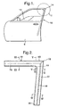
Figure 1 shows avehicle door 8 carrying a sealing and guidingchannel arrangement 10 in which a pane ofwindow glass 12 is slidable in a vertical direction as it is raised from or lowered into the lower part of -thedoor 8. The sealing and guidingarrangement 10 comprises a window frame and sealing and guiding channels mounted on the frame, as will be described. The sealing and guiding channels define asharp corner 14 and the construction in the region of the sharp corner is shown in enlarged detail inFigure 2 . - As shown in
Figure 2 , along the 'B' pillar of the vehicle, the sealing and guidingarrangement 10 comprises astrip portion 16. Thestrip portion 16 is of channel form to receive thewindow pane 12 and comprises an outer channel wall 16A (on the outside of the window pane) and an inner channel 16B (on the inside of the window pane). - Along the top of the window frame (and along the 'A' pillar of the vehicle), the sealing and guiding
channel arrangement 10 comprises astrip portion 18. Thestrip portion 18 is of also channel form to receive thewindow pane 12 and comprises an outer channel wall 18A (that is, a channel wall on the outside of the window pane) and an inner channel wall 18B (that is, a channel wall on the inside of the window pane 12). - The two
strip portions sharp corner 14. - The stiff window frame on which the
strip portions Figures 1 and 2 . The construction of the window frame, and the manner in which thestrip portions - At the
sharp corner 14, the window frame is smoothly radiussed as shown dotted at 19 and this part of the frame is covered over by aflap 20 forming part of the sealing and guidingchannel 10 in a manner to be explained. - In a manner to be explained in more detail below, the sealing and guiding
strip channel 10 is produced, such as by extrusion, from flexible material such as plastics or rubber. It is designed to provide a weather-proof seal for the edge of the window glass and also to impose low friction on the movement of the glass. -
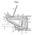
Figure 3 shows a section on the line IV-IV ofFigure 2 , that is, along the 'B' pillar. The stiff window frame is shown generally at 21 and comprises a rigid channel formed by bending over theouter panel 22 of the vehicle door and then forming the bent-over portion into channel form. Thewindow frame 21 is completed by theinner panels flange 26. - The
strip portion 16 is made of extruded plastics or rubber material and is of integral channel-form comprising abase 28 andside walls side wall 30 extends in one direction to form a lip (a "cosmetic lip") 34 which covers over the edge of theflange 26 and extends in the other direction to form a longer and moreflexible lip 36 which extends partway across the mouth of the channel. The distal edge of thewall 32 is extended to form a shortflexible lip 38. Adjacent thebase 28 of the channel is afurther lip 40. Thewindow pane 12 is guided within the channel as it slides in a vertical direction by thelips window glass 12 are advantageously covered with layers offlock 42, or another suitable low-friction coating. - The outside of the
base 28 of theportion 16 has short outwardly extendinglips strip portion 16 within the channel of thewindow frame 21. - Different parts of the
strip portion 16 may have different hardnesses. -
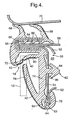
Figure 4 is a cross-section on the line III-III ofFigure 2 . Here, the window frame shown generally at 50 is formed bypanels flange 58 projecting outwardly of the door. Thepanels flange 58 to form ahollow space 60 and then come together again to form afurther flange 62 where they are again joined together. - The
strip portion 18 is again extruded integrally from plastics or rubber material and defines achannel 64 which embraces theflange 58 to hold thestrip portion 18 in position. The extruded material may carry integral inwardly extendinglips 66 to assist in securing the sealing and guiding strip in position on the flange and a reinforcingcarrier 67 may be embedded in the extruded material. The reinforcingcarrier 67 may be formed from any suitable relatively rigid material, such as metal or plastics. - The extruded material of the strip portion on one outside wall of the
channel 64 carries largeflexible sealing lips 68 which, when thevehicle door 8 is closed, seal against theroof line 70 of the vehicle. - The material on the outside of the base of the
channel 64 carries are-entrant lip 72. The material adjacent the mouth of thechannel 58 is extended to form alimb 74 which lies against thedoor panel 54 and terminates in a lip (a "cosmetic lip") 76 which embraces the edge of theflange 62. In addition, the distal end of thelimb 74 integrally carries a largeflexible lip 78 which extends towards thelip 72 so that, together, these lips define the channel for receiving the window pane 12 (shown dotted). Afurther lip 80 extends partway across the base of this channel. - The surfaces of the
lips window pane 12 may carry layers offlock 42, or another suitable low-friction coating. - The
limb 74 is further clamped to the window frame by means of a resilientlydeformable protrusion 82 having an enlargedhead portion 84 which is pushed through anaperture 86 in thepanel 54 and into thehollow space 60. After passing through theaperture 86, the enlargedhead 84 resiles and presses against thepanel 54 around the edges of theaperture 86. - It will be noted that the extruded plastics or rubber material of the
strip portion 16 ofFigure 3 is provided with a longitudinally extending hollow cavity orchamber 90 located near the distal edge of thechannel side wall 30. A similar longitudinally extendinghollow chamber 90 is provided in the material of thestrip portion 18 shown inFigure 4 , this hollow chamber being located at the distal end of thelimb 74. - As explained in connection with
Figure 2 , thewindow frame 12 includes a portion 19 (shown dotted) which smoothly bridges across the sharp corner. In other words, thedoor panels 23,24 (Figure 3 ) are progressively extended in length (in the direction towards the centre of the window opening), in the immediate vicinity of thesharp angle 14, this increase in length being progressively greater in the direction up the "B" pillar towards thesharp corner 16. Similarly, the lengths of thedoor panels 52 and 54 (Figure 4 ) progressively increase in the direction along the roof line towards thesharp corner 16. -
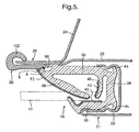
Figure 5 shows a section on the line VI-VI ofFigure 2 , the section plane being closer to thesharp corner 16 than the section plane IV-IV ofFigure 3 .Figure 5 shows that the general-shape of the window frame and thestrip portion 16 is similar to that shown inFigure 3 , except that thepanels - Similarly,
Figure 6 is a section on the line V-V ofFigure 2 , the section plane being closer to thesharp angle 16 than the section plane III-III shown inFigure 4 . Here, again, the configuration of the window frame and of thestrip portion 18 is generally the same as is shown inFigure 4 , except for the extended lengths of thepanels - As explained above, in constructing the sealing and guiding
channel 10 for the window opening, separate sealing and guidingstrip portions Figures 3 and4 , are extruded and one end of each such strip is mitre-cut and the two cut ends are brought together and joined at thesharp angle 14. However, because of the extended lengths of thepanels 23 and 24 (as shown inFigure 5 ) and 52 and 54 (as shown inFigure 6 ), it is necessary to modify the configuration of the sealing and guidingstrip portions sharp angle 14. - As shown in
Figure 5 , this is achieved (for the strip portion 16) by cutting through the extruded material along the dotted line shown at 92 (inFigure 3 ) adjacent to the wall of thehollow chamber 90, so as to remove thecosmetic lip 34. Similarly, and as shown inFigure 6 , a cut is made through the extruded material along the dotted line shown at 94 (inFigure 4 ) immediately adjacent thehollow chamber 90, so as to remove thecosmetic lip 76. These cutting actions take place, of course, only over those parts of the lengths of thestrip portions sharp corner 14, where the lengths of the panels forming the respective window frame portions have been extended. - It should be understood that the cut may be made in a different position to that shown at 92 or 94.
- After the
cosmetic lips strip portions Figures 5 and6 ), carrying acosmetic lip 102, into position on bothstrip portions flap 20 becomes joined to the sealing and guidingstrip portions Figure 5 ) and 94 (Figure 6 ). It is preferred in this embodiment to mould theflap 20 to the sealing and guidingstrip portions flock 42 in regions B to the heat and pressure required for the moulding operation. This reduces or prevents damage to theflock 42, so that theflock 42 will have a neat and attractive appearance, the flock extending completely up to the point where theflap 20 abuts thelip 78. - It is possible to mould the
flap 20 to the sealing and guidingstrip portions Figure 5 ) and 94 (Figure 6 ). If, however, theflap 20 is moulded to the sealing and guidingstrip portions flock 42 to the surface of thelip 78 near the region B, but instead to leave a non-flocked surface area between theflock 42 and the region B. Flock applied to this area may be damaged by the moulding process and might have an unattractive appearance, and there may not be a visually distinct line at the point where theflap 20 meets thelip 78. - The
cosmetic lip 102 carried by the moulded-onflap 20 embraces the flange produced where the ends of theextended panels 23,26 (Fig. 5 ) meet and where theextended panels 52,54 (Figure 6 ) meet. -
Figures 7 and8 correspond generally toFigures 4 and6 except that the window frame on which thestrip portion 18 is mounted is not shown inFigures 7 and8 . Parts inFigures 7 and8 corresponding to parts inFigures 4 and6 are similarly referenced. - In
Figures 7 and8 , thehollow chamber 90 is not formed within the extruded material but is replaced by ahollow cavity 90A. The largeflexible lip 78 has a "foot" 78A which is produced by the extrusion process so as to be separate from the extruded material of thecosmetic lip 76.Figure 9 (showing part, only, ofFigure 7 ) shows the relative positioning of the distal edge of thefoot 78A and theadjacent surface 76A of thecosmetic lip 76 at the exit of the extruder and shows a gap 'G' between them. However, at the exit of the extruder, a suitable roller arrangement is provided which forces thedistal edge 78A of thefoot 78 into firm contact with thesurface 76A of thecosmetic lip 76. Because the material has only just emerged from the extruder, the two parts which are pressed firmly together by the roller arrangement become adhered to each other (for example, by the cross-linking process which continues after extrusion), thereby forming thecavity 90A. In this way, therefore, no unsightly gap is visible to an observer viewing into the channel which receives the window pane. As an alternative to pressing the two parts together and causing them to adhere or stick to one another, the parts may be pressed together so that they abut one another but are not adhered together. - In the region of the
sharp angle 14, the smoothlyradiussed part 19 of the window frame (seeFigure 2 ) is covered over by aflap 20 as explained. As shown inFigure 8 , therefore, a cut is made along aline 94A to separate the material of thefoot 78A of thelip 78 from the material of thecosmetic lip 76 and thecosmetic lip 76 is removed. Then, a moulding operation is carried out to produce theextended flap 20 carrying thecosmetic lip 102 which thus embraces the ends of theextended panels 52, 54 (Figure 6 , but not shown inFigure 8 ). - In
Figure 8 theflap 20 is shown partially filling.thehollow cavity 90A. It should be understood that the material of theflap 20 could completely fill thehollow cavity 90A, so that there is no void. - The region A where the
flap 20 is moulded onto the material of the window channel is not externally visible, being hidden behind the distal edge of thefoot 78A. Theflap 20 may be only moulded onto the window channel at region A, or it may additionally (or alternatively) be moulded onto the window channel at region B, where thedistal edge 78A of thefoot 78 meets theflap 20. - Advantageously, in this embodiment, the
flap 20 is made from TPE, instead of conventional EPDM. TPE can be formed and moulded onto other components at a lower mould temperature than is required for EPDM. The moulding process for the TPE flap is therefore less likely to damage theflock 42 at thedistal edge 78A of thefoot 78. - However, it should be understood that the
flap 20 could be formed of EPDM (or any other suitable material). If theflap 20 is formed of EPDM and is moulded onto the window channel at region B, then it may be preferred to not applyflock 42 to thedistal edge 78A of thefoot 78, because flock at this region may be damaged by the heat of the moulding operation and may have an unattractive appearance. - The use of TPE is also advantageous because it can be recycled relatively easily.
- Along the B pillar of the window frame, the strip portion 16 (
Figures 3 and5 ) may be modified in the same way as described with reference toFigures 7 ,8 and9 , to produce acavity 90A instead of the cavity orchamber 90. The moulding operation can thus be arranged to join thestrip portions flap 20, carrying thecosmetic lip 102, onto both strip portions where they meet at the corner of the window frame. - Although the foregoing description has illustrated the construction in the region of a
sharp corner 14, the same general form of construction can be used in cases where there is no sharp corner but some other form of change of direction such as a corner with a less sharp angle or a curve or bend, for example where the A or C pillar meets the roof.
Claims (27)
- A sealing or guiding strip (16) comprising a body made of flexible material for mounting on a panel (54) having an edge (62), the panel (54) being more rigid than the flexible material and varying in size so that the panel has a first region of relatively small extent and a second region of relatively large extent, wherein the body overlies the first region of the panel (54) in use and partially overlies the second region of the panel (54) in use, and has an edge with a hollow cavity (90) formed in the body adjacent only to the edge of the body and an integral formation (76) at the edge of the body arranged to juxtapose with the edge (62) of the panel (54) along the first region of the panel (54), the integral edge formation (76) being removable, at a region corresponding to the second region of the panel (54), along a cut line (92) extending into the hollow cavity (90), the strip comprising furthermore a separate edge formation part (20) of extended size for replacing the integral edge formation (76), said separate edge formation part (20) being secured, when mounted on the panel, to the body along said cut line (92) for juxtaposing with the edge (62) of the panel (54) in the second region and for overlying the panel (54) in the second region.
- A strip (16) according to claim 1, wherein the body is produced by an extrusion process which also produces the hollow chamber.
- A strip (16) according to claim 1, wherein the body is produced using an extrusion process and in which the hollow cavity (90) is produced by pressing together two parts of the material immediately after the extrusion process so that they become secured together during the subsequent processing but leaving between them the hollow cavity (90).
- A strip (16) according to any preceding claim, in which in the second region the panel progressively changes in size and the separate edge formation correspondingly changes in size.
- A strip (16) according to any preceding claim, in which the separate edge formation is produced by a moulding operation.
- A strip (16) according to claim 5, in which the moulding operation secures the separate edge formation to the strip (16).
- A strip (16) according to any preceding claim, in which the hollow cavity (90) extends along the whole length of the strip (16).
- A strip (16) according to any preceding claim, which is secured to a second strip (18).
- A strip (16) according to claim 8, which is secured to the second strip (18) by a moulding operation.
- A strip (16) according to claim 9, in which the moulding operation which secures it to the second strip (18) also secures the separate edge formation (20).
- A strip (16) according to any one of the preceding claims, in which the edge formation (20) comprises TPE.
- A strip (16) according to any preceding claim, which is shaped to define a channel for receiving a pane of window glass (12) for a window opening, and in which the panel is part of a rigid frame (21) for the window opening.
- A strip (16) according to any one of claims 1 to 11, which defines a channel for receiving a pane of window glass (12) for a predetermined window opening, the said panel forming part of a frame (21) for the window opening and the second region being a region adjacent a change in direction of the window frame (21).
- A strip (16) according to claim 13, in combination with a second strip (18) which also defines a channel for receiving the pane of window glass (12), the two strips (18) being secured together at the change in direction of the window frame (21).
- A strip (16) according to claim 14, in which the separate edge formation (20) is also secured to the second strip (18).
- A window frame arrangement for a window opening, comprising a stiff window frame (21) having a smoothly radiussed region (19) extending across a change in direction of the window opening, and two sealing or guiding strips (16,18) according to any one of claims 1 to 11, wherein the panel (54) is part of the frame (21), the smoothly radiussed region (19) of the frame (21) corresponding to the second region of relatively large extent of the panel (54), each strip (16,18) defining a channel for receiving a pane of window glass (12) for the opening and which are secured together at the change in direction, the edge formation (76) of each strip (16,18) being arranged to engage with an edge of the window frame (21) along a portion of the length of the strip (16,18) outside the smoothly radiussed region (19) of the frame (21) and at the first region of relatively small extent of the panel (54), and the separate edge formation part (20) engaging an edge of the window frame (21) in the smoothly radiussed region (19) of the frame (21) and at the second region of relatively large extent of the panel (54).
- An arrangement according to claim 16, in which the separate edge formation part (20) is secured to the strips (16,18) along the cut lines (92,94) of each of them.
- An arrangement according to claim 16 or 17, in which the integral edge formation and the separate edge formation part (20) are each shaped to form a cosmetic lip (34,76).
- An arrangement according to any one of claims 16 to 18, in which the change in direction of the window opening is a sharp corner of the window frame (21).
- A method of making a sealing or guiding strip (16), the method including forming a body made of flexible material for mounting on a panel (54) having an edge (62), the panel (54) being more rigid than the flexible material and varying in size so that the panel has a first region of relatively small extent and a second region of relatively large extent, wherein the body overlies the first region of the panel (54) in use and partially overlies the second region of the panel, (54) in use, the body has an edge with a hollow cavity (90) formed in the body adjacent only to the edge of the body and an integral formation (76) formed at the edge of the body arranged to juxtapose with the edge (62) of the panel (54) along the first region of the panel (54), characterized by the integral edge formation (76) being removed, at a region corresponding to the second region of the panel, along a cut line (92) extending into the hollow cavity (90) and being replaced by a separate edge formation part (20) of extended size, which is secured to the body along said cut line (92) for juxtaposing with the edge (62) of the panel (54) in the second region and for overlying the panel (54) in the second region.
- The method of claim 20, wherein the body is produced by an extrusion process which also produces the hollow chamber.
- The method of claim 20, wherein the body is produced using an extrusion process and in which the hollow cavity (90) is produced by pressing together two parts of the material immediately after the extrusion process so that they become secured together during the subsequent processing but leaving between them the hollow cavity (90).
- The method according to claims 20,21 or 22, in which the separate edge formation is produced by a moulding operation.
- The method according to claim 23, in which the moulding operation secures the separate edge formation to the strip (16).
- The method according to claims 20,21,22,23 or 24, including securing the said strip (16) to a second strip (18).
- The method according to claim 25, including securing the said strip (16) to the second strip (18) by a moulding operation.
- The method according to claim 26, in which the moulding operation which secures it to the second strip (18) also secures the separate edge formation (20).
Applications Claiming Priority (5)
| Application Number | Priority Date | Filing Date | Title |
|---|---|---|---|
| GB0228290 | 2002-12-04 | ||
| GB0228290A GB0228290D0 (en) | 2002-12-04 | 2002-12-04 | Window sealing and guiding arrangements |
| GB0230327A GB0230327D0 (en) | 2002-12-04 | 2002-12-31 | Window sealing and guiding arrangements |
| GB0230327 | 2002-12-31 | ||
| PCT/IB2003/005622 WO2004050408A1 (en) | 2002-12-04 | 2003-12-01 | Window sealing and guiding arrangements |
Publications (3)
| Publication Number | Publication Date |
|---|---|
| EP1567382A1 EP1567382A1 (en) | 2005-08-31 |
| EP1567382B1 true EP1567382B1 (en) | 2008-06-25 |
| EP1567382B8 EP1567382B8 (en) | 2008-08-13 |
Family
ID=32472156
Family Applications (1)
| Application Number | Title | Priority Date | Filing Date |
|---|---|---|---|
| EP03812241A Expired - Lifetime EP1567382B8 (en) | 2002-12-04 | 2003-12-01 | Window sealing and guiding arrangements |
Country Status (4)
| Country | Link |
|---|---|
| US (1) | US20060150522A1 (en) |
| EP (1) | EP1567382B8 (en) |
| AU (1) | AU2003302632A1 (en) |
| WO (1) | WO2004050408A1 (en) |
Families Citing this family (15)
| Publication number | Priority date | Publication date | Assignee | Title |
|---|---|---|---|---|
| EP1805051B1 (en) * | 2004-10-27 | 2013-11-20 | Henniges Automotive Sealing Systems North America, Inc. | Sealing or guiding assembly and method of making it |
| GB0423875D0 (en) | 2004-10-27 | 2004-12-01 | Gdx North America Inc | Sealing or guiding assemblies and methods of making them |
| ES1059026Y (en) * | 2004-11-29 | 2005-06-16 | Seat Sa | GUIDE FOR ELEVABLE CRYSTALS OF VEHICLE DOOR WINDOWS. |
| ATE462596T1 (en) * | 2005-04-04 | 2010-04-15 | Henniges Automotive Sealing Sy | SEALING OR GUIDING ARRANGEMENTS FOR WINDOWS AND INSTALLATION METHODS |
| GB2429027A (en) * | 2005-08-12 | 2007-02-14 | Gdx North America Inc | Window sealing and guiding arrangements |
| DE102006060390B3 (en) * | 2006-12-20 | 2008-02-07 | Metzeler Automotive Profile Systems Gmbh | Door sealing profile for e.g. car, has sealing section with sealing lip extending in longitudinal direction, and auxiliary section provided and arranged in area of curvature at base of sealing lip |
| DE102008060288B4 (en) | 2008-12-03 | 2011-05-12 | Csa Germany Gmbh & Co. Kg | weatherstrip |
| US8631609B2 (en) * | 2009-04-16 | 2014-01-21 | Cooper-Standard Automotive Inc. | Integral trim to seal off weatherstrip and remove need for foam pads |
| JP6123524B2 (en) * | 2013-07-02 | 2017-05-10 | スズキ株式会社 | Door structure |
| US9290083B2 (en) * | 2013-12-18 | 2016-03-22 | Ford Global Technologies, Llc | Glass sealing system |
| DE102016117957A1 (en) * | 2016-09-23 | 2018-03-29 | Cooper Standard GmbH | Sealing arrangement for a motor vehicle window, sealing compound and method for producing a seal composite |
| DE112018002398B4 (en) * | 2017-05-11 | 2024-09-12 | Henniges Automotive Sealing Systems North America, Inc. | Seal arrangement |
| JP6960346B2 (en) * | 2018-02-06 | 2021-11-05 | 日産自動車株式会社 | Automotive door weather strip |
| WO2022245897A1 (en) * | 2021-05-18 | 2022-11-24 | Henniges Automotive Sealing Systems North America, Inc. | Sealing profile for a flushed window |
| CN216580061U (en) | 2022-01-14 | 2022-05-24 | 瀚德(中国)汽车密封系统有限公司 | Zero-order-difference vehicle door structure and vehicle door |
Family Cites Families (12)
| Publication number | Priority date | Publication date | Assignee | Title |
|---|---|---|---|---|
| GB1431460A (en) * | 1973-07-12 | 1976-04-07 | Schlegel Uk Ltd | Method of forming corners in elastomeric cellular strip |
| DE3616661A1 (en) * | 1986-05-16 | 1987-11-26 | Audi Ag | POETRY |
| US4949507A (en) * | 1990-01-18 | 1990-08-21 | The Standard Products Company | One-piece expandable weatherstrip |
| US5042201A (en) * | 1990-01-18 | 1991-08-27 | The Standard Products Company | One-piece weatherstrip with constant cross-section at corner bends |
| US5269101A (en) * | 1991-07-29 | 1993-12-14 | Toyoda Gosei Co., Ltd. | Automotive weatherstrip |
| GB2285471B (en) * | 1994-01-11 | 1997-02-12 | Draftex Ind Ltd | Sealing or guiding assemblies and methods of making them |
| US6023888A (en) * | 1996-09-25 | 2000-02-15 | Schlegel Corporation | Door and window channel seal |
| GB2321268B (en) * | 1997-01-17 | 2000-06-21 | Draftex Ind Ltd | Sealing or guiding assemblies and methods of making them |
| GB2353553B (en) * | 1999-08-27 | 2003-05-21 | Draftex Ind Ltd | Sealing and guiding strips |
| JP2001233060A (en) * | 2000-02-21 | 2001-08-28 | Toyoda Gosei Co Ltd | Trim and glass run mounting structure for automotive door |
| JP3885470B2 (en) * | 2000-08-23 | 2007-02-21 | 豊田合成株式会社 | Glass run for vehicle and manufacturing method thereof |
| EP1293372B1 (en) * | 2001-09-14 | 2004-12-01 | Toyoda Gosei Co., Ltd. | Automotive weather strip |
-
2003
- 2003-12-01 EP EP03812241A patent/EP1567382B8/en not_active Expired - Lifetime
- 2003-12-01 AU AU2003302632A patent/AU2003302632A1/en not_active Abandoned
- 2003-12-01 US US10/537,502 patent/US20060150522A1/en not_active Abandoned
- 2003-12-01 WO PCT/IB2003/005622 patent/WO2004050408A1/en not_active Ceased
Also Published As
| Publication number | Publication date |
|---|---|
| EP1567382B8 (en) | 2008-08-13 |
| AU2003302632A1 (en) | 2004-06-23 |
| WO2004050408A1 (en) | 2004-06-17 |
| US20060150522A1 (en) | 2006-07-13 |
| EP1567382A1 (en) | 2005-08-31 |
Similar Documents
| Publication | Publication Date | Title |
|---|---|---|
| EP0628439B1 (en) | Seal assembly for movable window for a vehicle | |
| EP1567382B1 (en) | Window sealing and guiding arrangements | |
| US8479449B2 (en) | Sealing, trimming and guiding strip | |
| US6996936B1 (en) | Sealing and guiding strip for a window with insert for corner of the window frame | |
| US8782954B2 (en) | Glass run | |
| US5839232A (en) | Sealing or guiding assemblies | |
| US5136773A (en) | Method of forming a shaped section for guiding and sealing a movable window | |
| JP4344809B2 (en) | Door weather strip | |
| US20090071077A1 (en) | Automotive glass run | |
| US12263722B2 (en) | Glass run and method of manufacturing the same | |
| US20100001550A1 (en) | Sealing or guiding assemblies and methods of making them | |
| EP0605092B1 (en) | Sealing or guiding strip, window frame assembly, and method of making window frame assembly | |
| US20070194539A1 (en) | Sealing, trimming or guiding strips | |
| JP2004123007A (en) | Door sealing structure for automobile | |
| EP1843910B1 (en) | Sealing or guiding assemblies and methods of making them | |
| EP0799735A1 (en) | Sealing and guiding strips | |
| JP2007161200A (en) | Glass run for automobile | |
| GB2429027A (en) | Window sealing and guiding arrangements | |
| JP2005329728A (en) | Glass run for automobile | |
| CN1745000A (en) | Window sealing and guiding arrangements | |
| GB2426275A (en) | Sealing or guiding assembly for a closure member eg window | |
| JPH06286531A (en) | Weather strip for automobile | |
| JP2006151059A (en) | Glass run for automobile | |
| JPH04353016A (en) | Window molding for vehicle and its manufacture | |
| JP2006335079A (en) | Glass run for automobile and its manufacturing method |
Legal Events
| Date | Code | Title | Description |
|---|---|---|---|
| PUAI | Public reference made under article 153(3) epc to a published international application that has entered the european phase |
Free format text: ORIGINAL CODE: 0009012 |
|
| 17P | Request for examination filed |
Effective date: 20050608 |
|
| AK | Designated contracting states |
Kind code of ref document: A1 Designated state(s): AT BE BG CH CY CZ DE DK EE ES FI FR GB GR HU IE IT LI LU MC NL PT RO SE SI SK TR |
|
| AX | Request for extension of the european patent |
Extension state: AL LT LV MK |
|
| DAX | Request for extension of the european patent (deleted) | ||
| 17Q | First examination report despatched |
Effective date: 20050914 |
|
| GRAP | Despatch of communication of intention to grant a patent |
Free format text: ORIGINAL CODE: EPIDOSNIGR1 |
|
| GRAS | Grant fee paid |
Free format text: ORIGINAL CODE: EPIDOSNIGR3 |
|
| GRAA | (expected) grant |
Free format text: ORIGINAL CODE: 0009210 |
|
| AK | Designated contracting states |
Kind code of ref document: B1 Designated state(s): AT BE BG CH CY CZ DE DK EE ES FI FR GB GR HU IE IT LI LU MC NL PT RO SE SI SK TR |
|
| REG | Reference to a national code |
Ref country code: GB Ref legal event code: FG4D |
|
| RAP2 | Party data changed (patent owner data changed or rights of a patent transferred) |
Owner name: HENNIGES AUTOMOTIVE SEALING SYSTEMS NORTH AMERICA, |
|
| REG | Reference to a national code |
Ref country code: CH Ref legal event code: EP |
|
| REF | Corresponds to: |
Ref document number: 60321815 Country of ref document: DE Date of ref document: 20080807 Kind code of ref document: P |
|
| REG | Reference to a national code |
Ref country code: IE Ref legal event code: FG4D |
|
| NLT2 | Nl: modifications (of names), taken from the european patent patent bulletin |
Owner name: HENNIGES AUTOMOTIVE SEALING SYSTEMS Effective date: 20080730 |
|
| PG25 | Lapsed in a contracting state [announced via postgrant information from national office to epo] |
Ref country code: FI Free format text: LAPSE BECAUSE OF FAILURE TO SUBMIT A TRANSLATION OF THE DESCRIPTION OR TO PAY THE FEE WITHIN THE PRESCRIBED TIME-LIMIT Effective date: 20080625 Ref country code: SI Free format text: LAPSE BECAUSE OF FAILURE TO SUBMIT A TRANSLATION OF THE DESCRIPTION OR TO PAY THE FEE WITHIN THE PRESCRIBED TIME-LIMIT Effective date: 20080625 |
|
| PG25 | Lapsed in a contracting state [announced via postgrant information from national office to epo] |
Ref country code: AT Free format text: LAPSE BECAUSE OF FAILURE TO SUBMIT A TRANSLATION OF THE DESCRIPTION OR TO PAY THE FEE WITHIN THE PRESCRIBED TIME-LIMIT Effective date: 20080625 Ref country code: NL Free format text: LAPSE BECAUSE OF FAILURE TO SUBMIT A TRANSLATION OF THE DESCRIPTION OR TO PAY THE FEE WITHIN THE PRESCRIBED TIME-LIMIT Effective date: 20080625 |
|
| NLV1 | Nl: lapsed or annulled due to failure to fulfill the requirements of art. 29p and 29m of the patents act | ||
| PG25 | Lapsed in a contracting state [announced via postgrant information from national office to epo] |
Ref country code: PT Free format text: LAPSE BECAUSE OF FAILURE TO SUBMIT A TRANSLATION OF THE DESCRIPTION OR TO PAY THE FEE WITHIN THE PRESCRIBED TIME-LIMIT Effective date: 20081125 Ref country code: SE Free format text: LAPSE BECAUSE OF FAILURE TO SUBMIT A TRANSLATION OF THE DESCRIPTION OR TO PAY THE FEE WITHIN THE PRESCRIBED TIME-LIMIT Effective date: 20080925 Ref country code: CZ Free format text: LAPSE BECAUSE OF FAILURE TO SUBMIT A TRANSLATION OF THE DESCRIPTION OR TO PAY THE FEE WITHIN THE PRESCRIBED TIME-LIMIT Effective date: 20080625 Ref country code: ES Free format text: LAPSE BECAUSE OF FAILURE TO SUBMIT A TRANSLATION OF THE DESCRIPTION OR TO PAY THE FEE WITHIN THE PRESCRIBED TIME-LIMIT Effective date: 20081006 |
|
| PG25 | Lapsed in a contracting state [announced via postgrant information from national office to epo] |
Ref country code: RO Free format text: LAPSE BECAUSE OF FAILURE TO SUBMIT A TRANSLATION OF THE DESCRIPTION OR TO PAY THE FEE WITHIN THE PRESCRIBED TIME-LIMIT Effective date: 20080625 Ref country code: BE Free format text: LAPSE BECAUSE OF FAILURE TO SUBMIT A TRANSLATION OF THE DESCRIPTION OR TO PAY THE FEE WITHIN THE PRESCRIBED TIME-LIMIT Effective date: 20080625 Ref country code: SK Free format text: LAPSE BECAUSE OF FAILURE TO SUBMIT A TRANSLATION OF THE DESCRIPTION OR TO PAY THE FEE WITHIN THE PRESCRIBED TIME-LIMIT Effective date: 20080625 |
|
| PG25 | Lapsed in a contracting state [announced via postgrant information from national office to epo] |
Ref country code: EE Free format text: LAPSE BECAUSE OF FAILURE TO SUBMIT A TRANSLATION OF THE DESCRIPTION OR TO PAY THE FEE WITHIN THE PRESCRIBED TIME-LIMIT Effective date: 20080625 Ref country code: DK Free format text: LAPSE BECAUSE OF FAILURE TO SUBMIT A TRANSLATION OF THE DESCRIPTION OR TO PAY THE FEE WITHIN THE PRESCRIBED TIME-LIMIT Effective date: 20080625 Ref country code: BG Free format text: LAPSE BECAUSE OF FAILURE TO SUBMIT A TRANSLATION OF THE DESCRIPTION OR TO PAY THE FEE WITHIN THE PRESCRIBED TIME-LIMIT Effective date: 20080925 |
|
| PLBE | No opposition filed within time limit |
Free format text: ORIGINAL CODE: 0009261 |
|
| STAA | Information on the status of an ep patent application or granted ep patent |
Free format text: STATUS: NO OPPOSITION FILED WITHIN TIME LIMIT |
|
| 26N | No opposition filed |
Effective date: 20090326 |
|
| PG25 | Lapsed in a contracting state [announced via postgrant information from national office to epo] |
Ref country code: MC Free format text: LAPSE BECAUSE OF NON-PAYMENT OF DUE FEES Effective date: 20081231 |
|
| REG | Reference to a national code |
Ref country code: CH Ref legal event code: PL |
|
| GBPC | Gb: european patent ceased through non-payment of renewal fee |
Effective date: 20081201 |
|
| PG25 | Lapsed in a contracting state [announced via postgrant information from national office to epo] |
Ref country code: IT Free format text: LAPSE BECAUSE OF FAILURE TO SUBMIT A TRANSLATION OF THE DESCRIPTION OR TO PAY THE FEE WITHIN THE PRESCRIBED TIME-LIMIT Effective date: 20080625 |
|
| REG | Reference to a national code |
Ref country code: IE Ref legal event code: MM4A |
|
| REG | Reference to a national code |
Ref country code: FR Ref legal event code: ST Effective date: 20090831 |
|
| PG25 | Lapsed in a contracting state [announced via postgrant information from national office to epo] |
Ref country code: CH Free format text: LAPSE BECAUSE OF NON-PAYMENT OF DUE FEES Effective date: 20081231 Ref country code: LI Free format text: LAPSE BECAUSE OF NON-PAYMENT OF DUE FEES Effective date: 20081231 Ref country code: IE Free format text: LAPSE BECAUSE OF NON-PAYMENT OF DUE FEES Effective date: 20081201 |
|
| PG25 | Lapsed in a contracting state [announced via postgrant information from national office to epo] |
Ref country code: GB Free format text: LAPSE BECAUSE OF NON-PAYMENT OF DUE FEES Effective date: 20081201 |
|
| PG25 | Lapsed in a contracting state [announced via postgrant information from national office to epo] |
Ref country code: FR Free format text: LAPSE BECAUSE OF NON-PAYMENT OF DUE FEES Effective date: 20081231 |
|
| PG25 | Lapsed in a contracting state [announced via postgrant information from national office to epo] |
Ref country code: HU Free format text: LAPSE BECAUSE OF FAILURE TO SUBMIT A TRANSLATION OF THE DESCRIPTION OR TO PAY THE FEE WITHIN THE PRESCRIBED TIME-LIMIT Effective date: 20081226 Ref country code: CY Free format text: LAPSE BECAUSE OF FAILURE TO SUBMIT A TRANSLATION OF THE DESCRIPTION OR TO PAY THE FEE WITHIN THE PRESCRIBED TIME-LIMIT Effective date: 20080625 Ref country code: LU Free format text: LAPSE BECAUSE OF NON-PAYMENT OF DUE FEES Effective date: 20081201 |
|
| PG25 | Lapsed in a contracting state [announced via postgrant information from national office to epo] |
Ref country code: TR Free format text: LAPSE BECAUSE OF FAILURE TO SUBMIT A TRANSLATION OF THE DESCRIPTION OR TO PAY THE FEE WITHIN THE PRESCRIBED TIME-LIMIT Effective date: 20080625 |
|
| PG25 | Lapsed in a contracting state [announced via postgrant information from national office to epo] |
Ref country code: GR Free format text: LAPSE BECAUSE OF FAILURE TO SUBMIT A TRANSLATION OF THE DESCRIPTION OR TO PAY THE FEE WITHIN THE PRESCRIBED TIME-LIMIT Effective date: 20080926 |
|
| PGFP | Annual fee paid to national office [announced via postgrant information from national office to epo] |
Ref country code: DE Payment date: 20171129 Year of fee payment: 15 |
|
| REG | Reference to a national code |
Ref country code: DE Ref legal event code: R119 Ref document number: 60321815 Country of ref document: DE |
|
| PG25 | Lapsed in a contracting state [announced via postgrant information from national office to epo] |
Ref country code: DE Free format text: LAPSE BECAUSE OF NON-PAYMENT OF DUE FEES Effective date: 20190702 |