EP1545780B1 - Systeme microfluidique modulaire - Google Patents
Systeme microfluidique modulaire Download PDFInfo
- Publication number
- EP1545780B1 EP1545780B1 EP03793893A EP03793893A EP1545780B1 EP 1545780 B1 EP1545780 B1 EP 1545780B1 EP 03793893 A EP03793893 A EP 03793893A EP 03793893 A EP03793893 A EP 03793893A EP 1545780 B1 EP1545780 B1 EP 1545780B1
- Authority
- EP
- European Patent Office
- Prior art keywords
- fluid
- base board
- accordance
- microfluidic system
- aperture
- Prior art date
- Legal status (The legal status is an assumption and is not a legal conclusion. Google has not performed a legal analysis and makes no representation as to the accuracy of the status listed.)
- Expired - Lifetime
Links
- 239000012530 fluid Substances 0.000 claims abstract description 129
- 230000008878 coupling Effects 0.000 claims abstract description 23
- 238000010168 coupling process Methods 0.000 claims abstract description 23
- 238000005859 coupling reaction Methods 0.000 claims abstract description 23
- 230000000694 effects Effects 0.000 claims abstract description 16
- 238000000034 method Methods 0.000 claims abstract description 16
- 238000010276 construction Methods 0.000 claims abstract description 10
- 239000000463 material Substances 0.000 claims description 29
- 239000000758 substrate Substances 0.000 claims description 14
- 238000004891 communication Methods 0.000 claims description 13
- 239000002131 composite material Substances 0.000 claims description 10
- 239000000126 substance Substances 0.000 claims description 10
- 239000002904 solvent Substances 0.000 claims description 5
- 239000003251 chemically resistant material Substances 0.000 claims description 4
- 238000012423 maintenance Methods 0.000 claims description 4
- 230000037361 pathway Effects 0.000 claims description 4
- 239000012780 transparent material Substances 0.000 claims description 4
- 239000010410 layer Substances 0.000 description 33
- 239000004593 Epoxy Substances 0.000 description 9
- 229920000642 polymer Polymers 0.000 description 9
- 239000004696 Poly ether ether ketone Substances 0.000 description 8
- 229920002530 polyetherether ketone Polymers 0.000 description 8
- 238000013461 design Methods 0.000 description 6
- 230000006870 function Effects 0.000 description 6
- 230000008569 process Effects 0.000 description 6
- 230000008901 benefit Effects 0.000 description 5
- 229920003229 poly(methyl methacrylate) Polymers 0.000 description 5
- 239000004926 polymethyl methacrylate Substances 0.000 description 5
- 230000000717 retained effect Effects 0.000 description 5
- 230000001747 exhibiting effect Effects 0.000 description 4
- 238000007689 inspection Methods 0.000 description 4
- 238000006243 chemical reaction Methods 0.000 description 3
- 238000004128 high performance liquid chromatography Methods 0.000 description 3
- 238000003780 insertion Methods 0.000 description 3
- 230000037431 insertion Effects 0.000 description 3
- 238000004519 manufacturing process Methods 0.000 description 3
- 239000004033 plastic Substances 0.000 description 3
- 229920003023 plastic Polymers 0.000 description 3
- 239000004810 polytetrafluoroethylene Substances 0.000 description 3
- 229920001343 polytetrafluoroethylene Polymers 0.000 description 3
- 238000013341 scale-up Methods 0.000 description 3
- XUIMIQQOPSSXEZ-UHFFFAOYSA-N Silicon Chemical compound [Si] XUIMIQQOPSSXEZ-UHFFFAOYSA-N 0.000 description 2
- 238000013459 approach Methods 0.000 description 2
- 238000003491 array Methods 0.000 description 2
- 230000009286 beneficial effect Effects 0.000 description 2
- 239000003054 catalyst Substances 0.000 description 2
- 239000003153 chemical reaction reagent Substances 0.000 description 2
- 239000011248 coating agent Substances 0.000 description 2
- 238000000576 coating method Methods 0.000 description 2
- 238000011982 device technology Methods 0.000 description 2
- 239000011521 glass Substances 0.000 description 2
- 239000007788 liquid Substances 0.000 description 2
- 239000013307 optical fiber Substances 0.000 description 2
- 238000012545 processing Methods 0.000 description 2
- 230000008439 repair process Effects 0.000 description 2
- 230000010076 replication Effects 0.000 description 2
- 239000011347 resin Substances 0.000 description 2
- 229920005989 resin Polymers 0.000 description 2
- 239000010703 silicon Substances 0.000 description 2
- 229910052710 silicon Inorganic materials 0.000 description 2
- 230000009471 action Effects 0.000 description 1
- 238000004026 adhesive bonding Methods 0.000 description 1
- 238000005842 biochemical reaction Methods 0.000 description 1
- 230000008859 change Effects 0.000 description 1
- 239000012141 concentrate Substances 0.000 description 1
- 239000004020 conductor Substances 0.000 description 1
- 230000002950 deficient Effects 0.000 description 1
- 238000001514 detection method Methods 0.000 description 1
- 238000011161 development Methods 0.000 description 1
- 238000005516 engineering process Methods 0.000 description 1
- 238000005530 etching Methods 0.000 description 1
- 239000000835 fiber Substances 0.000 description 1
- 239000010408 film Substances 0.000 description 1
- 238000001914 filtration Methods 0.000 description 1
- PCHJSUWPFVWCPO-UHFFFAOYSA-N gold Chemical compound [Au] PCHJSUWPFVWCPO-UHFFFAOYSA-N 0.000 description 1
- 239000010931 gold Substances 0.000 description 1
- 229910052737 gold Inorganic materials 0.000 description 1
- 238000013537 high throughput screening Methods 0.000 description 1
- 230000002209 hydrophobic effect Effects 0.000 description 1
- 238000001746 injection moulding Methods 0.000 description 1
- 239000002648 laminated material Substances 0.000 description 1
- 238000003754 machining Methods 0.000 description 1
- 238000005259 measurement Methods 0.000 description 1
- 239000002184 metal Substances 0.000 description 1
- 229910052751 metal Inorganic materials 0.000 description 1
- 238000001053 micromoulding Methods 0.000 description 1
- 230000003287 optical effect Effects 0.000 description 1
- 238000012856 packing Methods 0.000 description 1
- 239000010702 perfluoropolyether Substances 0.000 description 1
- 238000000206 photolithography Methods 0.000 description 1
- 239000004038 photonic crystal Substances 0.000 description 1
- 229920000058 polyacrylate Polymers 0.000 description 1
- 229920000139 polyethylene terephthalate Polymers 0.000 description 1
- 238000005086 pumping Methods 0.000 description 1
- 230000004044 response Effects 0.000 description 1
- 239000002356 single layer Substances 0.000 description 1
- 238000010183 spectrum analysis Methods 0.000 description 1
- 238000003860 storage Methods 0.000 description 1
- 239000010409 thin film Substances 0.000 description 1
- 230000007704 transition Effects 0.000 description 1
Images


Classifications
-
- B—PERFORMING OPERATIONS; TRANSPORTING
- B01—PHYSICAL OR CHEMICAL PROCESSES OR APPARATUS IN GENERAL
- B01J—CHEMICAL OR PHYSICAL PROCESSES, e.g. CATALYSIS OR COLLOID CHEMISTRY; THEIR RELEVANT APPARATUS
- B01J8/00—Chemical or physical processes in general, conducted in the presence of fluids and solid particles; Apparatus for such processes
- B01J8/18—Chemical or physical processes in general, conducted in the presence of fluids and solid particles; Apparatus for such processes with fluidised particles
-
- B—PERFORMING OPERATIONS; TRANSPORTING
- B01—PHYSICAL OR CHEMICAL PROCESSES OR APPARATUS IN GENERAL
- B01J—CHEMICAL OR PHYSICAL PROCESSES, e.g. CATALYSIS OR COLLOID CHEMISTRY; THEIR RELEVANT APPARATUS
- B01J19/00—Chemical, physical or physico-chemical processes in general; Their relevant apparatus
- B01J19/0093—Microreactors, e.g. miniaturised or microfabricated reactors
-
- B—PERFORMING OPERATIONS; TRANSPORTING
- B01—PHYSICAL OR CHEMICAL PROCESSES OR APPARATUS IN GENERAL
- B01F—MIXING, e.g. DISSOLVING, EMULSIFYING OR DISPERSING
- B01F25/00—Flow mixers; Mixers for falling materials, e.g. solid particles
- B01F25/40—Static mixers
- B01F25/42—Static mixers in which the mixing is affected by moving the components jointly in changing directions, e.g. in tubes provided with baffles or obstructions
- B01F25/43—Mixing tubes, e.g. wherein the material is moved in a radial or partly reversed direction
- B01F25/433—Mixing tubes wherein the shape of the tube influences the mixing, e.g. mixing tubes with varying cross-section or provided with inwardly extending profiles
- B01F25/4331—Mixers with bended, curved, coiled, wounded mixing tubes or comprising elements for bending the flow
-
- B—PERFORMING OPERATIONS; TRANSPORTING
- B01—PHYSICAL OR CHEMICAL PROCESSES OR APPARATUS IN GENERAL
- B01F—MIXING, e.g. DISSOLVING, EMULSIFYING OR DISPERSING
- B01F33/00—Other mixers; Mixing plants; Combinations of mixers
- B01F33/30—Micromixers
-
- B—PERFORMING OPERATIONS; TRANSPORTING
- B01—PHYSICAL OR CHEMICAL PROCESSES OR APPARATUS IN GENERAL
- B01J—CHEMICAL OR PHYSICAL PROCESSES, e.g. CATALYSIS OR COLLOID CHEMISTRY; THEIR RELEVANT APPARATUS
- B01J8/00—Chemical or physical processes in general, conducted in the presence of fluids and solid particles; Apparatus for such processes
- B01J8/18—Chemical or physical processes in general, conducted in the presence of fluids and solid particles; Apparatus for such processes with fluidised particles
- B01J8/24—Chemical or physical processes in general, conducted in the presence of fluids and solid particles; Apparatus for such processes with fluidised particles according to "fluidised-bed" technique
-
- B—PERFORMING OPERATIONS; TRANSPORTING
- B01—PHYSICAL OR CHEMICAL PROCESSES OR APPARATUS IN GENERAL
- B01L—CHEMICAL OR PHYSICAL LABORATORY APPARATUS FOR GENERAL USE
- B01L3/00—Containers or dishes for laboratory use, e.g. laboratory glassware; Droppers
-
- B—PERFORMING OPERATIONS; TRANSPORTING
- B01—PHYSICAL OR CHEMICAL PROCESSES OR APPARATUS IN GENERAL
- B01L—CHEMICAL OR PHYSICAL LABORATORY APPARATUS FOR GENERAL USE
- B01L3/00—Containers or dishes for laboratory use, e.g. laboratory glassware; Droppers
- B01L3/50—Containers for the purpose of retaining a material to be analysed, e.g. test tubes
- B01L3/502—Containers for the purpose of retaining a material to be analysed, e.g. test tubes with fluid transport, e.g. in multi-compartment structures
- B01L3/5027—Containers for the purpose of retaining a material to be analysed, e.g. test tubes with fluid transport, e.g. in multi-compartment structures by integrated microfluidic structures, i.e. dimensions of channels and chambers are such that surface tension forces are important, e.g. lab-on-a-chip
- B01L3/502715—Containers for the purpose of retaining a material to be analysed, e.g. test tubes with fluid transport, e.g. in multi-compartment structures by integrated microfluidic structures, i.e. dimensions of channels and chambers are such that surface tension forces are important, e.g. lab-on-a-chip characterised by interfacing components, e.g. fluidic, electrical, optical or mechanical interfaces
-
- B—PERFORMING OPERATIONS; TRANSPORTING
- B01—PHYSICAL OR CHEMICAL PROCESSES OR APPARATUS IN GENERAL
- B01F—MIXING, e.g. DISSOLVING, EMULSIFYING OR DISPERSING
- B01F2215/00—Auxiliary or complementary information in relation with mixing
- B01F2215/04—Technical information in relation with mixing
- B01F2215/0413—Numerical information
- B01F2215/0418—Geometrical information
- B01F2215/0431—Numerical size values, e.g. diameter of a hole or conduit, area, volume, length, width, or ratios thereof
-
- B—PERFORMING OPERATIONS; TRANSPORTING
- B01—PHYSICAL OR CHEMICAL PROCESSES OR APPARATUS IN GENERAL
- B01J—CHEMICAL OR PHYSICAL PROCESSES, e.g. CATALYSIS OR COLLOID CHEMISTRY; THEIR RELEVANT APPARATUS
- B01J2219/00—Chemical, physical or physico-chemical processes in general; Their relevant apparatus
- B01J2219/00781—Aspects relating to microreactors
- B01J2219/00783—Laminate assemblies, i.e. the reactor comprising a stack of plates
-
- B—PERFORMING OPERATIONS; TRANSPORTING
- B01—PHYSICAL OR CHEMICAL PROCESSES OR APPARATUS IN GENERAL
- B01J—CHEMICAL OR PHYSICAL PROCESSES, e.g. CATALYSIS OR COLLOID CHEMISTRY; THEIR RELEVANT APPARATUS
- B01J2219/00—Chemical, physical or physico-chemical processes in general; Their relevant apparatus
- B01J2219/00781—Aspects relating to microreactors
- B01J2219/00801—Means to assemble
- B01J2219/0081—Plurality of modules
-
- B—PERFORMING OPERATIONS; TRANSPORTING
- B01—PHYSICAL OR CHEMICAL PROCESSES OR APPARATUS IN GENERAL
- B01L—CHEMICAL OR PHYSICAL LABORATORY APPARATUS FOR GENERAL USE
- B01L2200/00—Solutions for specific problems relating to chemical or physical laboratory apparatus
- B01L2200/02—Adapting objects or devices to another
- B01L2200/026—Fluid interfacing between devices or objects, e.g. connectors, inlet details
- B01L2200/027—Fluid interfacing between devices or objects, e.g. connectors, inlet details for microfluidic devices
-
- B—PERFORMING OPERATIONS; TRANSPORTING
- B01—PHYSICAL OR CHEMICAL PROCESSES OR APPARATUS IN GENERAL
- B01L—CHEMICAL OR PHYSICAL LABORATORY APPARATUS FOR GENERAL USE
- B01L2300/00—Additional constructional details
- B01L2300/08—Geometry, shape and general structure
- B01L2300/0861—Configuration of multiple channels and/or chambers in a single devices
-
- B—PERFORMING OPERATIONS; TRANSPORTING
- B01—PHYSICAL OR CHEMICAL PROCESSES OR APPARATUS IN GENERAL
- B01L—CHEMICAL OR PHYSICAL LABORATORY APPARATUS FOR GENERAL USE
- B01L2300/00—Additional constructional details
- B01L2300/08—Geometry, shape and general structure
- B01L2300/0887—Laminated structure
-
- B—PERFORMING OPERATIONS; TRANSPORTING
- B01—PHYSICAL OR CHEMICAL PROCESSES OR APPARATUS IN GENERAL
- B01L—CHEMICAL OR PHYSICAL LABORATORY APPARATUS FOR GENERAL USE
- B01L3/00—Containers or dishes for laboratory use, e.g. laboratory glassware; Droppers
- B01L3/50—Containers for the purpose of retaining a material to be analysed, e.g. test tubes
- B01L3/502—Containers for the purpose of retaining a material to be analysed, e.g. test tubes with fluid transport, e.g. in multi-compartment structures
- B01L3/5027—Containers for the purpose of retaining a material to be analysed, e.g. test tubes with fluid transport, e.g. in multi-compartment structures by integrated microfluidic structures, i.e. dimensions of channels and chambers are such that surface tension forces are important, e.g. lab-on-a-chip
- B01L3/502707—Containers for the purpose of retaining a material to be analysed, e.g. test tubes with fluid transport, e.g. in multi-compartment structures by integrated microfluidic structures, i.e. dimensions of channels and chambers are such that surface tension forces are important, e.g. lab-on-a-chip characterised by the manufacture of the container or its components
-
- Y—GENERAL TAGGING OF NEW TECHNOLOGICAL DEVELOPMENTS; GENERAL TAGGING OF CROSS-SECTIONAL TECHNOLOGIES SPANNING OVER SEVERAL SECTIONS OF THE IPC; TECHNICAL SUBJECTS COVERED BY FORMER USPC CROSS-REFERENCE ART COLLECTIONS [XRACs] AND DIGESTS
- Y10—TECHNICAL SUBJECTS COVERED BY FORMER USPC
- Y10T—TECHNICAL SUBJECTS COVERED BY FORMER US CLASSIFICATION
- Y10T436/00—Chemistry: analytical and immunological testing
- Y10T436/25—Chemistry: analytical and immunological testing including sample preparation
- Y10T436/2575—Volumetric liquid transfer
Definitions
- the invention relates to a microfluidic system having a modular construction for rapid assembly and disassembly, and a method of providing such a system.
- Microfluidic devices and systems have become increasingly important in recent years for performing large numbers of different chemical and/or biological operations on a manageable scale, since they allow a large number of chemical or biochemical reactions to be carried out as part of an analytical and/or synthetic process in a relatively small liquid volume.
- Such miniaturised analytical or synthetic operations are generally more efficient, producing increased response times and reduce the requirement for potentially expensive reagents.
- a modular microfluidic system as claimed in claim 1. It comprises at least one base board having a plurality of fluidly linked fluid supply apertures on one or both sides thereof, a plurality of microfluidic modules adapted to be detachably attached to the base board, each having one or more fluid inlets and/or outlets, and a plurality of fluid couplings to effect releasable substantially fluid-tight fluid connection between a module and a base board via a supply aperture on the base board and an inlet/outlet on the module.
- the system comprises at least one fluid source aperture fluidly linked thereto to supply source fluid to the system, and/or at least one fluid output aperture fluidly linked thereto to output fluid from the system.
- Source and/or outlet apertures may be provided in direct communication to the baseboard or via modules. A plurality of such fluid source apertures and/or fluid output apertures may be provided.
- the fluid supply may be gaseous or liquid. More than one fluid may be supplied to any given system.
- the microfluidic circuit is built up on the base board, with the system being formed in modular fashion upon the base board chip, rather than being integrated therewith in conventional manner. Fluid is supplied to the constructed microfluidic system via the fluid source aperture in the baseboard or by direct introduction into a module.
- the base board chip is preferably constructed with a pattern of at least partly interconnecting microfluidic channels to provide a plurality of fluid channels and/or chambers linking in fluid communication at least some of the supply apertures to each other and/or to the source aperture.
- the fluid supply passages within the modules act in co-operation therewith to complete a desired microfluidic circuit when the modular structure is assembled, the circuit serving to distribute fluid to interconnection points on the board and hence to the modules.
- the assembled system may provide a plurality of such circuits functioning in association or independently.
- Chip module to base board interconnections may be made conveniently compact and simple, whilst at the same time connections between the board and external equipment can utilise well established fittings for interfacing to that equipment. Intermixing of different materials and device technology is enabled (for example glass chips on a polymer board). In the same way a choice of external systems such as external pumps as well as on-board or module-surface mounted pumps and valves etc. is offered.
- the system of the invention offers flexibility of design choice.
- a simple baseboard design may be provided with exchangeable complex modules, or complex systems may be included within the baseboard, with the modules attachable thereto being simple and/or disposable. Seals and connections between module and board can be selected according to module function.
- the overall system provides for simple inspection and maintenance, flexibility of use, and ease of repair to systems, for example by replacing only a module which is defective rather than an entire system.
- a microfluidic module in accordance with the invention comprises one or more microfluidic devices.
- a microfluidic device may comprise any known element of a microfluidic system, including without limitation an active device unit, such as a reactor, heater, cooler, analyser, detector, mixer, processor, separator or the like, a fluid function unit such as a pump, valve, filter or the like or merely a fluid channel, chamber or manifold to complete a particular microfluidic circuit.
- Microfluidic devices in accordance with the invention may be three dimensional or generally planar.
- the devices are generally planar.
- Each module has a generally planar construction to be incorporated upon a generally planar baseboard.
- Inlet/outlet apertures are most conveniently provided on one of the planar faces of such a module.
- Supply apertures are most conveniently provided on a planar face of the baseboard, and source aperture(s) may be provided at an edge or edge face or the same or opposite planar face thereof.
- each module preferably has a generally planar sandwich construction, comprising at least one inner sandwich layer defining a fluid channel and/or chamber portion, and at least one cover layer covering and effecting enclosure of the same.
- the module comprises at least one sandwich layer defining an enclosed fluid channel and/or chamber portion, for example consisting of paired sandwich elements into the surface of at least one of which channels are created such that the pair assembled together define such an enclosure, with cover layers at either side thereof. Further intermediate layers may be present.
- Active microfluidic elements may be incorporated within the channels and/or chambers so formed in the sandwich layer or additionally or alternatively may be provided upon the module surface in fluid communication with the channel therewithin.
- One or more inlet and/or outlet apertures are provided to effect a fluid communication between the channel and an external surface of the module, for fluid connection to the baseboard.
- a baseboard may be similarly constructed.
- the base board and of the modules may be fabricated conveniently in suitable plastics material. They may be constructed from monolithic blocks of material, from sandwich layers as above described, or from thin layer laminates or combinations thereof. Layers or materials which contact fluid in use are preferably fabricated when necessary from chemically resistant plastics material, such as epoxy, a photoimagable epoxy being most preferred. Suitable resistant thin film laminate materials might include epoxy glued PEN laminates. This gives good resistance with good fabricability of fluid channels and chambers. In sandwich structures, cover layers including fluid inlet/outlet ports which might also contact fluid in use are also preferably fabricated from materials exhibiting good chemical resistance, for example epoxy or other plastics such as polyetheretherketone (PEEK). Alternatively, materials may be given a suitably resistant coating in such areas.
- PEEK polyetheretherketone
- Chemical properties of merely structural cover or intermediate layers might be less critical. Likewise material selection might be less critical for components intended for use with fluids presenting a less harsh environment. In these cases less resistant materials such as PMMA, PET, acrylic polymers and the like might be suitable.
- any materials or layers and in particular cover layers might also be modified for specific properties, for example for transparency, for electrical, magnetic or dielectric properties, to provide mountings for externally mounted microfluidic device components etc.
- Metallic layers may be provided or incorporated, for example to serve as a conductor, resistive heater or otherwise.
- a substrate polymer that is optically transparent to enable easy inspection of the fluid path and/ or to allow measurements and/or is thermally transparent or transparent at other wavelengths for any purpose.
- a readily available polymer with good transparency that is also resistant to a wide range of solvents used in synthetic chemistry is not generally available.
- a substrate can be readily formed comprising a composite structure having areas of a transparent material (not necessarily exhibiting high chemical resistance) where required, and areas of a chemically resistant material (not necessarily exhibiting high transparency) at least in regions where solvent contact is possible, preventing contact with the less resistant transparent substrate material.
- a basic structure comprises transparent material but in which inserts of chemically resistant material are included in the substrate in regions where solvent contact is possible.
- a basic structure of chemically resistant material with "window" inserts of transparent material will serve the same purpose. Specific areas with other functionality will similarly readily suggest themselves.
- microfluidic will be understood to refer to microstructures having at least some sub-millimetre dimensions, microstructure in this case being used to refer to any of a variety of well known structures in such systems, including, but not limited to, the channels and chambers hereinabove described, that are capable of providing passage or storage for a fluid.
- a plurality of fluid couplings are provided to effect a fluid-tight connection between at least one fluid supply aperture on a base board and at least one inlet/outlet on a microfluidic device module.
- Fluid tight connection is preferably effected by interference fit between a coupling and a supply aperture, and couplings and apertures are sized and materials for their fabrication selected accordingly, for example being flexibly resilient at least in the region of connection.
- connecting means may be provided to hold the assembly together in use and assist in maintenance of a fluid-tight connection between modules and board by urging coupling and aperture into closer association and retaining thereat with a suitable urging force.
- Such connecting means may for example comprise spring clips, screws, bolts, clamps or like mechanical fixings.
- the connecting means connect modules and board together. There is no need for specific connecting means separately associated with each coupling/ aperture connection. One or a few mechanical fasteners can be used to hold together a system making multiple fluid connections.
- connecting means will typically be releasable as it is a feature of the invention that modules are readily assembled into multiple configurations and are able to be dissasembled by a user for example for reassembly into other configurations.
- the user may wish to use more permanent fixings to retain coupling and aperture in fluid-tight association on a semi-permanent or permanent basis, for example by permanent mechanical fixing or gluing, and a system in accordance with the invention allows a user to choose to do this.
- connection comprises a releasable coupling, for example in the form of a channel means removably insertable into a suitable recess in such a inlet/outlet/aperture to effect a fluid tight communicating connection therebetween.
- a channel means conveniently comprises a tubular element, in particular a rigid tubular element, for example being parallel sided, for example being square or rectangular, polygonal, or alternatively having a circular or elliptical cross section, with any recess into which such a tubular element is to be received preferably being shaped accordingly.
- the tubular element can be a separable and distinct unit.
- the tubular element preferably comprises a projecting ferrule integral with and projecting from a first aperture comprising either a fluid supply aperture in the base board or an inlet/outlet in the module, and adapted to be received in a recess comprised as a second aperture, correspondingly either an inlet/outlet in the module or a supply aperture in the base board.
- the ferrule projects generally perpendicularly from a generally planar surface, to effect a fluid connection between a base board and module adapted to lie generally parallel when connected.
- ferrules are provided which project above the surface of the base board to be received within recesses comprising the inlet/outlet apertures of modules to be attached thereto.
- Ferrules as above described can offer particular advantages.
- the ferrule system enables dead volume in fluid path between "chips" to be minimised.
- Use of ferrules allows higher density of interconnections than other fittings such as high-pressure liquid chromatography (HPLC) fittings and the like.
- Ferrules can withstand high pressures.
- Ferrules generally require a reduced thickness of material in which to be held compared to the thickness needed to hold a screw thread or like fitting, allowing much thinner layers, down to layers essentially comprising films, to be interconnected.
- One or a few mechanical fasteners can be used to hold together a system making multiple fluid connections through the ferrules.
- the ferrules ensure accurate mechanical alignment of fluid elements making accurate module placement easy.
- the internal bore and external diameter can be varied within limits, making it possible for the ferrule to incorporate microfluidic functionality.
- the internal bore could incorporate a filtration function, optionally comprising multiple holes (in manner analogous to a photonic crystal).
- the ferrule can be modified to a larger shape to include a reservoir function.
- the fluid coupling can incorporate additional functionality in that it includes within a fluid channel therewithin a fluidly active component, rather than serving merely as a channel.
- the fluid coupling could contain a non-return valve, for example a ball valve.
- the ball valve could conveniently be magnetically switchable valve.
- the fluid coupling could contain a catalyst frit or could incorporate a filter.
- Various switches could be conceived.
- a conducting for example metallic fluid coupling such as a metallic ferrule to effect an electrical as well as a fluid interconnection between modules and/or boards.
- a metallic coupling may optionally be provided with an insulating layer on a fluid and/or module contacting surface, effecting an electrical contact between modules and/or electrical contact with fluid therein.
- a ferrule based design offers particular flexibility in that the system may readily be provided with further functional interconnections (eg magnetic, optical) either integral with or separately from the ferrule.
- the ferrule can incorporate or be provided with a closure for closing a pathway not being used in a particular device combination allowing redundancy in pathway choice in base board for example during plug and play use.
- the closure may comprise a bung to be applied by a user, or an integral closure valve adapted to be operated manually, or to operate automatically on insertion of ferrule into recess.
- the invention hereinabove has been described in terms of a single baseboard with a plurality of modules disposed in a single layer thereupon. It will be readily appreciated that the invention is not so limited. A particular flexibility of the invention is that it allows for multi-level stacking of modules and/or primary base boards and/or intermediate level boards. Such intermediate level boards may serve merely to provide fluid connections in the form of channels, chambers or the like, or may also include active microfluidic components. Similarly, it will be understood that the invention encompasses modular structures comprising a plurality of modules as hereinbefore described and at least one primary base board, in which the base board is also optionally provided with active microfluidic components.
- any component adapted for use at an intermediate level will comprise at least one inlet aperture on a first "lower” surface and at least one outlet aperture on a second "upper” surface (it being understood that lower and upper are being used herein as a convenience to refer to surfaces proximal and distal to the base board, and not to imply any restrictive orientation).
- references herein to inlets/outlets in a module will be understood to apply equally where appropriate to such a lower aperture, and references herein to a base board fluid supply aperture will be understood to apply equally where appropriate to such an upper aperture in an intermediate level component. It is particularly easy to stack multiple layers using the preferred ferrule embodiment.
- fluid connections are effected by projecting ferrules between components adapted to lie generally parallel.
- ferrules are preferably provided at apertures in the upper surface of the base board and at apertures in the upper surface of all intermediate level modules, to be receivingly engaged in fluid tight connection within recessed portions at apertures on the lower surface of all intermediate level components and all top level components.
- Attachment of a module to the board, or of an upper layer module, to a lower layer module in multi-layer systems may be achieved by any suitable releasable attachment means, including without limitation screws or screw fixings, bayonet fittings whether quick release or not, push and snap fit connectors, vacuum or mechanical clamping connections, releasable mutually engageable resilient hook and felt pads, hooks, clips etc.
- the fluid couplings themselves especially in the preferred form as channel means in interference fit between pairs of linked apertures, for example ferrules engaged in interference fit in recesses, may assist in or even suffice to constitute such mechanical connection. However, additional mechanical connectors will usually be preferred.
- the system in accordance with the invention provides a plurality of interchangeable elements enabling a plurality of different microfluidic functions to be performed, on one or more levels.
- a method of providing a microfluidic system as a modular assembly as claimed in claim 19 comprises the steps of:
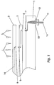
- FIG 1 illustrates in cross section the basic design of fluid connection in accordance with the preferred embodiment of the invention employing projecting ferrules.
- FIG. 1 Illustrated schematically in Figure 1 are a baseboard (1), a first level component layer (2) and a second level component layer (3). The three layers are shown in exploded view disassembled but aligned for assembly.
- Fluid connection within the system is effected by insertion of ferrules (7, 9) respectively provided at an upper supply aperture in the base board (1) and at an upper outlet aperture in the first level board (2) which are received in the recesses (6, 8) respectively provided in a lower surface of the first level board (2) and in a lower surface of the second level board (3).
- the connection employs simple parallel-sided holes to take PTFE tubes forming the ferrules (7, 9) although it will be understood that more complex holes and ferrules are possible.
- the ferrules are retained within the holes in interference fit to provide a fluid tight leak proof connection.
- fluid supply is effected via an inlet fluid source aperture (10) comprising flexible tubing (11) of 1/16 inch (1.5 mm) diameter retained within HPLC fittings (12).
- the fluid path is shown by the dark line (14).
- a mechanical load is applied in the direction of the arrows (L) to effect engagement between the ferrules (7, 9) and the recesses (6, 8). Additional mechanical fixings (not shown) might be provided to ensure a more secure mechanical connection between the components (1, 2, 3).
- a simple schematic device construction is illustrated in the exploded view in Figure 2.
- the example device has a sandwich layer structure comprising an external base layer (21) of polyetheretherketone (PEEK), a pair of inner layers (22) of photoimagable epoxy and an upper layer (24) of polymethylmethacrylate (PMMA) and internal layers (22).
- Channel means (23) are provided in the inner epoxy sandwich layer (22) to provide the necessary microfluidic microstructure.
- Fluid ports (25) through the upper layer (24) give a fluid communication from a surface of the completed device to the channel means (23) which form enclosed internal channels once the two parts illustrated in the exploded view of Figure 2 are assembled.
- the sandwich layer elements (22) and upper layer (24) contact fluid in use, respectively in the channels (23) and ports (25). Accordingly these are fabricated from materials exhibiting good chemical resistance, in the example respectively photimagable epoxy and PEEK. Properties of the merely structural lower layer (21) are less critical.
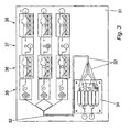
- a microfluidic reaction system in accordance with the invention is illustrated in plan view in Figure 3.
- the reactor comprises inlets for two supply fluids ("fluid A” and "fluid B"), and provides for three processing streams ("stream 1", "stream 2", "stream 3").
- the reactor comprises a baseboard (31) incorporating a plurality of fluid supply channels (32) therewithin.
- the base board has a number of microfluidic components mounted thereupon, being a manifold (34) to split the supply fluid (A, B) into the three streams (streams 1, 2, 3), and then within each stream a series of modules comprising a mixer chip (35), a detector chip (36), a reactor chip (37) and a further detector chip (36). These components are shown separately in Figures 4 to 8.
- a system constructed in accordance with the principles of the invention as illustrated by figure 3 offers admirable simplicity and flexibility, providing a number of advantages over conventional designs.
- it enables use of larger interconnect components and scaling from the macro to the micro world by microfluidic "fanning" (transition from large pitch to small pitch spacing between fluidic channels).
- Fittings from chip to board enable close packing of interconnections on ⁇ 2 mm square packed spacing or ⁇ 1 mm staggered spacing.
- FIG 4 illustrates in plan view the baseboard (31) of Figure 3 without the components attached.
- the fluid channel means provided within the baseboard (31) are illustrated more clearly.
- the manifold (34) of Figure 3 is illustrated in greater detail in plan view in Figure 5. It can be seen from Figure 5 how the manifold receives from a single inlet the two fluids (fluid A, fluid B) and produces 6 outlets, 1 to 6, effecting a paired supply of fluid A and fluid B to the three streams illustrated in Figure 3.
- the device is constructed in accordance with the principles of Figure 2.
- Channel size in the example is 150 ⁇ m by 50 ⁇ m. Routing is effected through 300 ⁇ m channels.
- the overall size of the device is 62 by 72 by 4 mm.
- Figure 6 illustrates in side view (above) and plan view (below) the micro mixer chip of Figure 3.
- the micromixer chip receives two fluid streams comprising fluid A and fluid B respectively in inlet A and inlet B. These are mixed together as they follow the flow channel (41) to the outlet.
- the chip is of a basic design as illustrated in Figure 2, with a channel size of 100 ⁇ m by 50 ⁇ m and an overall size of 45 by 25 by 4 mm. It is retained in position on the baseboard by means of the clamp (42).
- Figure 7 is a representation of a reactor chip (37) from Figure 3 shown in side view (above) and plan view (below). Fluid flows from inlet to outlet via the flow channel (51) thereby passing through the reactor portion (53).
- the reactor portion comprises a catalyst bed (54) 3 mm in diameter and 2 mm deep retained by the screw in plug (55).
- the overall assembly has a channel size of 100 ⁇ m by 50 ⁇ m, an overall size of 36 by 25 by 6 mm, and is retained in position by the clamp (52).
- Figure 8 illustrates the detector chip (36) of Figure 3 in side view (above) and plan view (below). Fluid flows from inlet to outlet via the flow channel (61).
- the detector's active area (68) includes a light source in the form of an LED (63) or an optical fibre (not shown) to an external source, a diffraction grating (64) and a light collector in the form of the optical fibre (65).
- a lens (66) in front of the light source collimates the light and a lens (67) in front of the light collecting fibre improves the light collection efficiency. Collected light is sent for spectral analysis.
- Additional electrical detection function is provided via groups of 3 gold microelectrodes (69), 110 ⁇ m wide on 200 ⁇ m pitch.
- Channel size is 400 ⁇ m by 400 ⁇ m, giving an overall device dimension of 50 x 30 x 5 mm.
- systems in accordance with the invention can be given enhanced functionality by using a combination of materials and components and by using composite substrates for the baseboard and chips to achieve the best combination of properties.
- a "window" substrate polymer that is transparent to enable easy inspection of the fluid path, but in which inserts are included in the substrate in the regions where solvent contact is possible; preventing contact with the "window” substrate.
- the insert is simply a cylinder traversing the substrate through which is drilled a fluid path way and recess to support a ferrule.
- the material of the insert can be chosen from high chemical resistance polymers such as PEEK or PTFE or in a curable resin formed by micromoulding or lithographically using a photoformable resin.
- the inserts can be produced by any method including machining or injection moulding.
- the concept of using a composite approach to achieve the required properties at the optimum location can also be extended to the microfluidic channel walls.
- the surface properties of the walls should ideally be matched to the desired flow characteristics of the material being transported by the channel. For example, if low wall contact resistance is required a low surface energy coating is a more convenient method of achieving the desired effect compared to producing the whole system in a low surface energy polymer.
- a photoimagable epoxy treated with Fluorolink S10 (Ausimont) - a di-triethoxysilane based on a linear perfluoropolyether backbone reduces the surface energy to 13 dynes/cm.
- the walls of the channels can alternatively be treated to make them hydrophilic or hydrophobic or to provide biocompatibility etc.
- a further benefit of the interconnected baseboard and processor chip concept underlying the present invention is the possibility of application to scale up by scale out.
- Scale out is the term often applied to increasing output from a processor chip performing, for example, a synthetic procedure by multiplying the number of processor chips. This preserves the reaction conditions for the channel dimensions optimised for a single process or series of processes which would otherwise change if the channel dimensions Were increased to achieve higher throughput.
- This can be achieved by the baseboard functioning as a manifold, supplying reagents to an array of processor chips.
- the manifold can provide a single sided input to multiple outputs from each processor chip).
- a manifold on one side can provide an interdigitated input and output array of channels or one side can provide an input manifold and a higher level board can provide an output manifold.
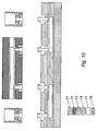
- FIGS 11 and 12 Examples of such arrangements exploiting the composite concept are shown in figures 11 and 12, respectively illustrating the use of a baseboard as a manifold for supplying fluid in parallel to an array of processors with multiple outputs from each processor chip and the use of baseboards as input and output manifolds for feeding processor chips in parallel for scale up by scale out or by processor replication.
- the shading key of Figures 9 and 10 is applied to the systems illustrated in figures 11 and 12.
- the interconnection system provides a ready means of developing processes by series interconnection of each operation with optimisation of each operation readily achieved by exchange of chips. Once a series of operations are optimised they can be conveniently integrated into a single chip and then if required converted into arrays with the baseboard providing multiple feeds for use in high throughput screening or the baseboard serving as input and output manifolds for process replication to scale up or achieve increased throughput by scale out. In this way very large numbers of chips can be arrayed to achieve a production capability.
- the complete system can be a complete hybrid of materials with for example the baseboard manifold being in polymer, the ferrule seals in polymer, the processor chips in glass, the pumping and valving system in metal possibly with internal polymer seals etc.
Claims (19)
- Système microfluide modulaire comprenant au moins une carte de base (1, 31) comportant une pluralité d'ouvertures d'alimentation en fluide reliées de manière fluide sur une de leur face ou leurs deux faces, une pluralité de modules microfluides (35, 36, 37) conçus pour être fixés de manière détachable à la carte de base, chacun comportant une ou plusieurs entrées et/ou sorties de fluide et une pluralité de raccords fluides pour effectuer une connexion libérable, étanche au fluide entre un module et une carte de base par l'intermédiaire d'une ouverture d'alimentation sur la carte de base et d'une entrée/sortie sur le module microfluide, un raccord fluide comprenant un moyen de canal (7, 9) pouvant être inséré dans un évidement formé de manière appropriée dans une telle entrée/sortie/ouverture pour effectuer une communication étanche au fluide entre eux.
- Système microfluide modulaire selon la revendication 1, dans lequel le moyen de canal comprend un élément tubulaire rigide, avec un évidement quelconque dans lequel un tel élément tubulaire doit être reçu en conséquence.
- Système microfluide modulaire selon la revendication 2, dans lequel l'élément tubulaire comprend une virole protubérante solidaire d'une première ouverture et dépassant de celle-ci, l'ouverture comprenant soit une ouverture d'alimentation en fluide dans la carte de base, soit une entrée/sortie dans le module, et étant conçue pour être reçue dans un évidement comprenant, en tant que seconde ouverture, de manière correspondante soit une entrée/sortie dans le module, soit une ouverture d'alimentation dans la carte de base.
- Système microfluide modulaire selon l'une quelconque des revendications précédentes, dans lequel la virole dépasse d'une manière globalement perpendiculaire depuis une surface globalement plane de la carte de base pour effectuer une connexion de fluide entre une carte de base et un module conçu pour s'étendre généralement parallèlement lorsqu'il est connecté.
- Système microfluide modulaire selon l'une quelconque des revendications précédentes, dans lequel le moyen de canal présente une section transversale circulaire ou elliptique.
- Système microfluide modulaire selon l'une quelconque des revendications précédentes, comprenant en outre au moins une ouverture de source de fluide reliée de manière fluide à celui-ci pour fournir du fluide de source au système et/ou au moins une ouverture de sortie de fluide reliée de manière fluide à celui-ci pour fournir en sortie du fluide provenant du système.
- Système microfluide modulaire selon l'une quelconque des revendications, dans lequel la carte de base est construite avec un motif de canaux microfluides d'interconnexion pour procurer une pluralité de canaux de fluides et/ou des chambres à utiliser pour relier par communication de fluide au moins certaines des ouvertures d'alimentation les unes aux autres et/ou à l'ouverture de source.
- Système microfluide modulaire selon l'une quelconque des revendications précédentes, dans lequel chaque module microfluide comprend un ou plusieurs dispositifs microfluides.
- Système microfluide modulaire selon la revendication 8, dans lequel les dispositifs microfluides comprennent des dispositifs sélectionnés parmi la liste comprenant un réacteur, un dispositif de chauffage, un dispositif de refroidissement, un analyseur, un détecteur, un mélangeur, un module de traitement, un séparateur ou autre, une pompe, une vanne, un filtre ou autre, ou un canal de fluide, une chambre ou un collecteur.
- Système microfluide modulaire selon l'une quelconque des revendications précédentes, dans lequel chaque module présente une construction globalement plane devant être incorporée dans une carte de base globalement plane.
- Système microfluide modulaire selon l'une quelconque des revendications précédentes, dans lequel des parties différentes de cartes et/ou de modules sont fabriquées à partir de matériaux différents pour procurer des exigences fonctionnelles différentes en ce qui concerne la transparence, la résistance de la structure, la résistance chimique et autres.
- Système microfluide modulaire selon la revendication 11, dans lequel une carte et/ou un module comprennent une structure composite présentant des zones d'un matériau transparent où cela est requis et des zones d'un matériau chimiquement résistant au moins dans des régions où un contact du solvant est possible, en empêchant un contact avec le matériau de substrat transparent moins résistant.
- Système microfluide modulaire selon l'une quelconque des revendications précédentes, dans lequel un moyen de connexion est prévu pour maintenir l'ensemble au cours de l'utilisation et contribuer au maintien d'une connexion étanche au fluide en sollicitant le raccord et l'ouverture en association plus étroite et en les retenant à ce niveau avec une force de sollicitation appropriée.
- Système microfluide modulaire selon l'une quelconque des revendications précédentes, dans lequel le canal tubulaire pouvant être inséré de manière amovible incorpore, ou est fourni avec, une fermeture destinée à fermer un chemin qui n'est pas utilisé dans une combinaison de dispositifs particulière.
- Système microfluide modulaire selon l'une quelconque des revendications précédentes, dans lequel le moyen de canal tubulaire comprend à l'intérieur d'un canal de fluide à l'intérieur de celui-ci un composant actif au niveau fluide.
- Système microfluide modulaire selon l'une quelconque des revendications précédentes, dans lequel le raccord fluide tubulaire est un raccord de canal tubulaire métallique, tel qu'une virole métallique pour effectuer une interconnexion aussi bien électrique que fluide.
- Système microfluide modulaire selon l'une quelconque des revendications précédentes, comprenant une pluralité de modules, une carte de base et une ou plusieurs cartes de niveau intermédiaire construites d'une manière identique à la carte de base, l'ensemble étant conçu pour un empilement multiniveau de modules et/ou de cartes de base et/ou de cartes de niveaux intermédiaires.
- Système microfluide modulaire selon la revendication 17, dans lequel des moyens de canaux comprenant des viroles tubulaires rigides sont prévus au niveau des ouvertures dans la surface supérieure de la carte de base et au niveau d'ouvertures dans la surface supérieure de tous les modules de niveau intermédiaire, pour être engagés par réception dans une connexion étanche au fluide à l'intérieur de parties en creux au niveau d'ouvertures sur la surface inférieure de tous les composants de niveau intermédiaire et de tous les composants du niveau supérieur.
- Procédé de fourniture d'un système microfluide en tant qu'ensemble modulaire comprenant les étapes consistant à :procurer au moins une carte de base comportant une pluralité d'ouvertures d'alimentation en fluide reliées de manière fluide sur une face ou les deux faces de celle-ci et une pluralité de canaux fluides et/ou de chambres reliant selon une communication de fluide, au moins certaines des ouvertures d'alimentation,procurer une pluralité de modules microfluides, chacun ayant une ou plusieurs entrées et/ou sorties de fluide et au moins un canal de fluide ou chambre en communication de fluide entre eux,un raccord fluide comprenant un moyen de canal pouvant être inséré dans un évidement formé de manière appropriée dans une telle entrée/sortie/ouverture pour effectuer une communication étanche au fluide entre eux,connectant les modules à la carte de base par l'intermédiaire des raccords fluides afin d'effectuer une connexion étanche au fluide libérable entre eux par l'intermédiaire d'une ouverture d'alimentation sur la carte de base et d'une entrée/sortie sur le module,de sorte que les canaux de fluides ou les chambres à l'intérieur des modules agissent en coopération avec les canaux de fluides ou les chambres dans la carte de base pour compléter un circuit microfluide souhaité.
Applications Claiming Priority (5)
| Application Number | Priority Date | Filing Date | Title |
|---|---|---|---|
| GB0220746A GB0220746D0 (en) | 2002-09-06 | 2002-09-06 | Microfluidic system |
| GB0220746 | 2002-09-06 | ||
| GB0313657 | 2003-06-13 | ||
| GB0313657A GB0313657D0 (en) | 2003-06-13 | 2003-06-13 | Microfluidic system |
| PCT/GB2003/003853 WO2004022233A1 (fr) | 2002-09-06 | 2003-09-05 | Systeme microfluidique modulaire |
Publications (2)
| Publication Number | Publication Date |
|---|---|
| EP1545780A1 EP1545780A1 (fr) | 2005-06-29 |
| EP1545780B1 true EP1545780B1 (fr) | 2007-02-28 |
Family
ID=31980017
Family Applications (1)
| Application Number | Title | Priority Date | Filing Date |
|---|---|---|---|
| EP03793893A Expired - Lifetime EP1545780B1 (fr) | 2002-09-06 | 2003-09-05 | Systeme microfluidique modulaire |
Country Status (10)
| Country | Link |
|---|---|
| US (1) | US7605002B2 (fr) |
| EP (1) | EP1545780B1 (fr) |
| JP (1) | JP2005537916A (fr) |
| KR (1) | KR101000797B1 (fr) |
| AT (1) | ATE355128T1 (fr) |
| AU (1) | AU2003264734A1 (fr) |
| DE (1) | DE60312186T2 (fr) |
| DK (1) | DK1545780T3 (fr) |
| ES (1) | ES2282726T3 (fr) |
| WO (1) | WO2004022233A1 (fr) |
Cited By (1)
| Publication number | Priority date | Publication date | Assignee | Title |
|---|---|---|---|---|
| KR100960670B1 (ko) | 2008-12-12 | 2010-05-31 | 한국전기연구원 | 모세관을 이용한 랩온어칩 및 그 제조 방법 |
Families Citing this family (105)
| Publication number | Priority date | Publication date | Assignee | Title |
|---|---|---|---|---|
| CA2290731A1 (fr) | 1999-11-26 | 2001-05-26 | D. Jed Harrison | Appareil et methode de piegeage de reactifs en forme de perles, dans le cadre d'un systeme d'analyse de microfluides |
| US6432290B1 (en) | 1999-11-26 | 2002-08-13 | The Governors Of The University Of Alberta | Apparatus and method for trapping bead based reagents within microfluidic analysis systems |
| EP1476209B1 (fr) * | 2002-02-18 | 2008-07-30 | Danfoss A/S | Dispositif d'administration d'un medicament sous forme fluide |
| EP1594694A4 (fr) | 2002-12-30 | 2010-01-20 | Univ California | Procedes et appareil pour la detection et l'analyse d'agents pathogenes |
| EP1694731B1 (fr) * | 2003-09-23 | 2012-03-28 | University Of North Carolina At Chapel Hill | Perfluoropolyethers photopolymerisables destines a etre utilises comme nouveaux materiaux dans des dispositifs microfluidiques |
| US8030057B2 (en) * | 2004-01-26 | 2011-10-04 | President And Fellows Of Harvard College | Fluid delivery system and method |
| CN102357352B (zh) | 2004-01-26 | 2015-08-12 | 哈佛大学 | 流体递送系统和方法 |
| JP4920427B2 (ja) * | 2004-02-17 | 2012-04-18 | エーアフェルト・ミクロテッヒニク・ベーテーエス・ゲゼルシャフト・ミット・ベシュレンクテル・ハフツング | マイクロミキサー |
| US7799553B2 (en) | 2004-06-01 | 2010-09-21 | The Regents Of The University Of California | Microfabricated integrated DNA analysis system |
| CN101073002B (zh) | 2004-09-15 | 2012-08-08 | 英特基因有限公司 | 微流体装置 |
| JP4657006B2 (ja) * | 2004-09-24 | 2011-03-23 | 財団法人神奈川科学技術アカデミー | マイクロチップコネクターとマイクロチップ構成体 |
| EP1864120B1 (fr) | 2005-04-01 | 2011-11-30 | Alere Switzerland GmbH | Station d'accueil pour une cartouche de capteur |
| WO2006114596A1 (fr) * | 2005-04-26 | 2006-11-02 | Aviza Technology Limited | Structures microfluidiques et leur procede de fabrication |
| JP5123847B2 (ja) | 2005-05-25 | 2013-01-23 | バイオ−ラド ラボラトリーズ インコーポレイテッド | 流体工学装置 |
| FR2891911B1 (fr) * | 2005-10-07 | 2008-04-25 | Horiba Abx Sas Soc Par Actions | "dispositif modulaire destine a l'analyse d'un fluide biologique, notamment sanguin" |
| US20080038714A1 (en) * | 2005-11-02 | 2008-02-14 | Affymetrix, Inc. | Instrument to Pneumatically Control Lab Cards and Method Thereof |
| GB0524854D0 (en) * | 2005-12-06 | 2006-01-11 | Epigem Ltd | Fine line bonding and/or sealing system and method |
| US7749365B2 (en) | 2006-02-01 | 2010-07-06 | IntegenX, Inc. | Optimized sample injection structures in microfluidic separations |
| EP1979079A4 (fr) | 2006-02-03 | 2012-11-28 | Integenx Inc | Dispositifs microfluidiques |
| US7766033B2 (en) | 2006-03-22 | 2010-08-03 | The Regents Of The University Of California | Multiplexed latching valves for microfluidic devices and processors |
| NL1031465C2 (nl) | 2006-03-30 | 2007-10-03 | C2V B V | Werkwijze voor het opbouwen van een inrichting met fluïdische en elektrische functies. |
| EP1854543B1 (fr) * | 2006-05-11 | 2011-04-06 | Corning Incorporated | Système de montage et d'interconnexion modulaire pour les dispositifs microfluidiques |
| US20110300034A1 (en) * | 2006-06-19 | 2011-12-08 | The Regents Of The University Of California | Disposable, High Pressure Microfluidic Chips |
| JP4938596B2 (ja) * | 2006-08-31 | 2012-05-23 | 京セラ株式会社 | 流路デバイス |
| WO2008052138A2 (fr) | 2006-10-25 | 2008-05-02 | The Regents Of The University Of California | Microdispositif à injection en ligne et système d'analyse d'adn intégré micro-usiné faisant intervenir ce microdispositif |
| US20090302190A1 (en) * | 2006-10-25 | 2009-12-10 | Fraunhofer-Gesellschaft Zur Foerderung Der Angewandten Forschung E.V. | Chip holder, fluidic system and chip holder system |
| US20100075425A1 (en) * | 2006-10-31 | 2010-03-25 | Burkert Werke Gmbh & Co. Kg | Modular laboratory apparatus for analysis and synthesis of liquids and method for analysis and synthesis of liquids |
| JP2008139129A (ja) * | 2006-12-01 | 2008-06-19 | Sumitomo Bakelite Co Ltd | 流路デバイス |
| US8617903B2 (en) * | 2007-01-29 | 2013-12-31 | The Invention Science Fund I, Llc | Methods for allergen detection |
| US20080181816A1 (en) * | 2007-01-29 | 2008-07-31 | Searete Llc, A Limited Liability Corporation | Systems for allergen detection |
| US10001496B2 (en) * | 2007-01-29 | 2018-06-19 | Gearbox, Llc | Systems for allergen detection |
| US20080180259A1 (en) * | 2007-01-29 | 2008-07-31 | Searete Llc, A Limited Liability Corporation Of The State Of Delaware | Devices for allergen detection |
| US20110039303A1 (en) | 2007-02-05 | 2011-02-17 | Stevan Bogdan Jovanovich | Microfluidic and nanofluidic devices, systems, and applications |
| WO2008135055A1 (fr) * | 2007-04-27 | 2008-11-13 | Siemens Aktiengesellschaft | Système microfluidique |
| ES2687620T3 (es) | 2007-05-04 | 2018-10-26 | Opko Diagnostics, Llc | Dispositivo y método para análisis en sistemas microfluídicos |
| US8454906B2 (en) | 2007-07-24 | 2013-06-04 | The Regents Of The University Of California | Microfabricated droplet generator for single molecule/cell genetic analysis in engineered monodispersed emulsions |
| KR20110030415A (ko) | 2008-01-22 | 2011-03-23 | 인터젠엑스 인크. | 만능 샘플 제조 시스템 및 집적 분석 시스템에서의 용도 |
| US7919062B2 (en) * | 2008-03-20 | 2011-04-05 | Corning Incorporated | Modular microfluidic system and method for building a modular microfludic system |
| US8222049B2 (en) | 2008-04-25 | 2012-07-17 | Opko Diagnostics, Llc | Flow control in microfluidic systems |
| EP2376226B1 (fr) | 2008-12-18 | 2018-09-12 | Opko Diagnostics, LLC | Stockage de réactifs amélioré dans des systèmes microfluidiques et articles et procédés associés |
| CN102341691A (zh) | 2008-12-31 | 2012-02-01 | 尹特根埃克斯有限公司 | 具有微流体芯片的仪器 |
| EP2391451B1 (fr) | 2009-02-02 | 2018-09-12 | Opko Diagnostics, LLC | Structures pour le contrôle des interactions de la lumière avec des dispositifs microfluidiques |
| US20100199750A1 (en) * | 2009-02-06 | 2010-08-12 | Arnold Don W | Microfludic Analysis System and Method |
| JP5340760B2 (ja) * | 2009-02-12 | 2013-11-13 | 倉敷紡績株式会社 | 流体制御方法及び流体制御装置 |
| US20100282766A1 (en) * | 2009-05-06 | 2010-11-11 | Heiko Arndt | Low-Dead Volume Microfluidic Component and Method |
| US8230744B2 (en) | 2009-05-06 | 2012-07-31 | Cequr Sa | Low-dead volume microfluidic circuit and methods |
| EP2251079A1 (fr) | 2009-05-11 | 2010-11-17 | Chemtrix B.V. | Système micro-fluide et son utilisation associée |
| CN102422164B (zh) * | 2009-05-15 | 2015-12-16 | 柯尼卡美能达株式会社 | 微芯片 |
| WO2010141326A1 (fr) | 2009-06-02 | 2010-12-09 | Integenx Inc. | Dispositif fluidique a soupapes a membrane |
| RU2559541C2 (ru) | 2009-06-05 | 2015-08-10 | Интедженкс Инк. | Универсальная система подготовки образцов и применение в интегрированной системе анализа |
| JP5702780B2 (ja) * | 2009-07-21 | 2015-04-15 | ユニバーシティ オブ バージニア パテント ファウンデーション | カテーテルシステム |
| KR101569836B1 (ko) * | 2009-10-28 | 2015-11-17 | 삼성전자주식회사 | 미세 유체 소자의 초기화 방법, 미세 유체 소자의 초기화 장치 및 미세 유체 소자 패키지 |
| PL2504105T3 (pl) | 2009-11-24 | 2021-06-28 | Opko Diagnostics, Llc | Mieszanie i dostarczanie płynów w układach mikroprzepływowych |
| US8584703B2 (en) | 2009-12-01 | 2013-11-19 | Integenx Inc. | Device with diaphragm valve |
| CN102939160B (zh) | 2010-04-16 | 2016-10-12 | 欧普科诊断有限责任公司 | 用于样本分析的系统和装置 |
| ITTO20100319A1 (it) * | 2010-04-20 | 2011-10-21 | Eltek Spa | Dispositivi microfluidici e/o attrezzature per dispositivi microfluidici |
| USD645971S1 (en) | 2010-05-11 | 2011-09-27 | Claros Diagnostics, Inc. | Sample cassette |
| US8512538B2 (en) | 2010-05-28 | 2013-08-20 | Integenx Inc. | Capillary electrophoresis device |
| EP2606154B1 (fr) | 2010-08-20 | 2019-09-25 | Integenx Inc. | Système d'analyse intégrée |
| US8763642B2 (en) | 2010-08-20 | 2014-07-01 | Integenx Inc. | Microfluidic devices with mechanically-sealed diaphragm valves |
| JP2013542051A (ja) | 2010-08-24 | 2013-11-21 | ケムトリックス ベーフェー | マイクロ流体装置 |
| US9579649B2 (en) * | 2010-10-07 | 2017-02-28 | Sandia Corporation | Fluid delivery manifolds and microfluidic systems |
| US9211378B2 (en) | 2010-10-22 | 2015-12-15 | Cequr Sa | Methods and systems for dosing a medicament |
| AU2012214157A1 (en) * | 2011-02-11 | 2013-08-29 | Code Footwear, Llc | Reconfigurable apparel manufacture and business processes |
| GB2488171B (en) * | 2011-02-21 | 2013-10-16 | Ion Science Ltd | Pneumatic manifold |
| US9233372B2 (en) | 2011-06-14 | 2016-01-12 | Corning Incorporated | Hybrid microfluidic assemblies |
| US10865440B2 (en) | 2011-10-21 | 2020-12-15 | IntegenX, Inc. | Sample preparation, processing and analysis systems |
| US20150136604A1 (en) | 2011-10-21 | 2015-05-21 | Integenx Inc. | Sample preparation, processing and analysis systems |
| DE102012100344A1 (de) * | 2012-01-17 | 2013-07-18 | Karlsruher Institut für Technologie | Mikroreaktor für katalytische Reaktionen |
| EP2626133A1 (fr) | 2012-02-10 | 2013-08-14 | Chemtrix B.V. | Système micro-fluidique |
| WO2013126732A1 (fr) | 2012-02-23 | 2013-08-29 | Schlumberger Canada Limited | Appareil et système de mesure de la teneur en asphaltènes d'une huile brute |
| TWI638277B (zh) | 2012-03-05 | 2018-10-11 | Opko診斷法有限責任公司 | 用於確定前列腺癌相關事件之機率之分析系統及方法 |
| WO2014011115A1 (fr) * | 2012-07-12 | 2014-01-16 | Agency For Science, Technology And Research | Raccord pour dispositif microfluidique, procédé permettant d'injecter un fluide dans le dispositif microfluidique en utilisant le raccord et procédé permettant de fournir et d'actionner une vanne |
| WO2014018770A1 (fr) * | 2012-07-25 | 2014-01-30 | The Charles Stark Draper Laboratory, Inc. | Plateforme modulaire destinée à la culture cellulaire intégrée de multiples tissus |
| US9192934B2 (en) | 2012-10-25 | 2015-11-24 | General Electric Company | Insert assembly for a microfluidic device |
| WO2014158367A1 (fr) | 2013-03-13 | 2014-10-02 | Opko Diagnostics, Llc | Mélange de fluides dans des systèmes fluidiques |
| CA2906345C (fr) * | 2013-03-16 | 2023-06-20 | Leslie Don ROBERTS | Cartouche d'analyse modulaire et autonome et systeme programmable de distribution de reactif |
| US10191071B2 (en) | 2013-11-18 | 2019-01-29 | IntegenX, Inc. | Cartridges and instruments for sample analysis |
| US10208332B2 (en) | 2014-05-21 | 2019-02-19 | Integenx Inc. | Fluidic cartridge with valve mechanism |
| EP3209410A4 (fr) | 2014-10-22 | 2018-05-02 | IntegenX Inc. | Systèmes et méthodes de préparation, de traitement et d'analyse d'échantillon |
| JP6929773B2 (ja) | 2014-12-12 | 2021-09-01 | オプコ・ダイアグノスティクス・リミテッド・ライアビリティ・カンパニーOpko Diagnostics,Llc | 成形によって形成される流体システムを含む培養チャネルを備える流体システム |
| US20180355298A1 (en) * | 2014-12-15 | 2018-12-13 | The Regents Of The University Of California | Multi-organ cell culture system and methods of use thereof |
| US9956558B2 (en) | 2015-07-24 | 2018-05-01 | HJ Science & Technology, Inc. | Reconfigurable microfluidic systems: homogeneous assays |
| WO2017019221A1 (fr) * | 2015-07-24 | 2017-02-02 | HJ Science & Technology, Inc. | Systèmes microfluidiques reconfigurables : dosages homogènes |
| US9733239B2 (en) | 2015-07-24 | 2017-08-15 | HJ Science & Technology, Inc. | Reconfigurable microfluidic systems: scalable, multiplexed immunoassays |
| US9956557B2 (en) | 2015-07-24 | 2018-05-01 | HJ Science & Technology, Inc. | Reconfigurable microfluidic systems: microwell plate interface |
| USD804682S1 (en) | 2015-08-10 | 2017-12-05 | Opko Diagnostics, Llc | Multi-layered sample cassette |
| US10184102B2 (en) | 2015-08-26 | 2019-01-22 | EMULATE, Inc. | Controlling pressure |
| JP6714603B2 (ja) * | 2015-10-09 | 2020-07-01 | シスメックス株式会社 | 検体処理チップ、検体処理装置および検体処理方法 |
| WO2017100457A1 (fr) | 2015-12-11 | 2017-06-15 | Opko Diagnostics, Llc | Systèmes fluidiques impliquant l'incubation d'échantillons et/ou de réactifs |
| BE1024344B1 (nl) * | 2016-07-04 | 2018-02-02 | PharmaFluidics N.V. | Productie van chemische reactoren |
| GB2560379A (en) | 2017-03-10 | 2018-09-12 | Epigem Ltd | Microfluidic device |
| JP7187477B2 (ja) * | 2017-04-06 | 2022-12-12 | エスアールアイ インターナショナル | マルチステップ化学反応を行うためのモジュール式システム、及びその使用法 |
| US11865535B2 (en) | 2017-04-20 | 2024-01-09 | Hewlett-Packard Development Company, L.P. | Microfluidic reaction system |
| WO2019083447A1 (fr) * | 2017-10-23 | 2019-05-02 | National University Of Singapore | Système microfluidique modulaire plan |
| WO2019122101A1 (fr) | 2017-12-21 | 2019-06-27 | Hte Gmbh The High Throughput Experimentation Company | Système de réacteur pour des réactions d'écoulement |
| WO2019213060A1 (fr) * | 2018-04-30 | 2019-11-07 | Protein Fluidics, Inc. | Puce d'écoulement de commutation fluidique sans valve et ses utilisations |
| CN112601947A (zh) * | 2018-07-10 | 2021-04-02 | 精密种植有限责任公司 | 农业采样系统及相关方法 |
| EP3778026A4 (fr) * | 2018-07-28 | 2022-01-19 | Korea Advanced Institute Of Science And Technology | Puce fluidique modulaire et système d'écoulement de fluide la comprenant |
| KR102375602B1 (ko) * | 2018-07-28 | 2022-03-18 | 한국과학기술원 | 모듈형 유체 칩 및 이를 포함하는 유체 유동 시스템 |
| KR102222994B1 (ko) * | 2018-11-29 | 2021-03-08 | 성균관대학교 산학협력단 | 모듈형 마이크로유체 시스템 |
| CN111551752B (zh) * | 2020-04-03 | 2021-10-08 | 深圳市科瑞达生物技术有限公司 | 一种化学发光免疫检测芯片及应用 |
| CN115178312A (zh) * | 2022-07-07 | 2022-10-14 | 浙江大学 | 一种基于光固化成形的可重构微流控移动拼图装置 |
| DE102022207704A1 (de) | 2022-07-27 | 2024-02-01 | Robert Bosch Gesellschaft mit beschränkter Haftung | Verteilereinheit für ein Analysegerät zum Analysieren einer in einer Mikrofluidikkartusche enthaltenen Probe, Analysegerät sowie Verfahren zum Herstellen einer Korpuseinheit für eine Verteilereinheit |
| CN115219072B (zh) * | 2022-08-18 | 2023-03-21 | 深圳职业技术学院 | 基于激光诱导荧光技术的微流体温度标定模块 |
Family Cites Families (16)
| Publication number | Priority date | Publication date | Assignee | Title |
|---|---|---|---|---|
| US4021117A (en) * | 1975-08-07 | 1977-05-03 | Hildegard Gohde | Process for automatic counting and measurement of particles |
| US5603351A (en) * | 1995-06-07 | 1997-02-18 | David Sarnoff Research Center, Inc. | Method and system for inhibiting cross-contamination in fluids of combinatorial chemistry device |
| US6190616B1 (en) * | 1997-09-11 | 2001-02-20 | Molecular Dynamics, Inc. | Capillary valve, connector, and router |
| US6209928B1 (en) * | 1998-06-04 | 2001-04-03 | The Regents Of The University Of California | Microfluidic interconnects |
| US7649153B2 (en) * | 1998-12-11 | 2010-01-19 | International Business Machines Corporation | Method for minimizing sample damage during the ablation of material using a focused ultrashort pulsed laser beam |
| US6707551B2 (en) * | 2000-01-24 | 2004-03-16 | Amnis Corporation | Multipass cavity for illumination and excitation of moving objects |
| DE19928412C2 (de) * | 1999-06-22 | 2002-03-21 | Agilent Technologies Inc | Versorgungselement für einen Labor-Mikrochip |
| JP2001137613A (ja) * | 1999-11-11 | 2001-05-22 | Kawamura Inst Of Chem Res | 抽出機構を有する微小ケミカルデバイス |
| JP4458313B2 (ja) * | 1999-12-02 | 2010-04-28 | 独立行政法人科学技術振興機構 | 化学集積回路 |
| JP2001194373A (ja) * | 2000-01-06 | 2001-07-19 | Olympus Optical Co Ltd | 超小型化学操作装置 |
| WO2002028531A1 (fr) * | 2000-10-06 | 2002-04-11 | Protasis Corporation | Cartouche a canal separateur de fluide dotee d'une fonction de chiffrement |
| AU2001296809A1 (en) * | 2000-10-10 | 2002-04-22 | Biotrove, Inc. | Apparatus for assay, synthesis and storage, and methods of manufacture, use, and manipulation thereof |
| US6536477B1 (en) * | 2000-10-12 | 2003-03-25 | Nanostream, Inc. | Fluidic couplers and modular microfluidic systems |
| JP2002139419A (ja) * | 2000-10-31 | 2002-05-17 | Nippon Sheet Glass Co Ltd | 微小流路素子及びその製造方法 |
| US6797139B2 (en) * | 2001-03-19 | 2004-09-28 | Applera Corporation | Detection cell for guiding excitation light therein and method for using same |
| NZ590166A (en) * | 2008-06-30 | 2013-09-27 | Microbix Biosystems Inc | Method and apparatus for sorting cells |
-
2003
- 2003-09-05 US US10/526,981 patent/US7605002B2/en not_active Expired - Fee Related
- 2003-09-05 JP JP2004533649A patent/JP2005537916A/ja active Pending
- 2003-09-05 AT AT03793893T patent/ATE355128T1/de not_active IP Right Cessation
- 2003-09-05 AU AU2003264734A patent/AU2003264734A1/en not_active Abandoned
- 2003-09-05 DE DE60312186T patent/DE60312186T2/de not_active Expired - Lifetime
- 2003-09-05 EP EP03793893A patent/EP1545780B1/fr not_active Expired - Lifetime
- 2003-09-05 ES ES03793893T patent/ES2282726T3/es not_active Expired - Lifetime
- 2003-09-05 KR KR1020057003845A patent/KR101000797B1/ko not_active IP Right Cessation
- 2003-09-05 WO PCT/GB2003/003853 patent/WO2004022233A1/fr active IP Right Grant
- 2003-09-05 DK DK03793893T patent/DK1545780T3/da active
Cited By (1)
| Publication number | Priority date | Publication date | Assignee | Title |
|---|---|---|---|---|
| KR100960670B1 (ko) | 2008-12-12 | 2010-05-31 | 한국전기연구원 | 모세관을 이용한 랩온어칩 및 그 제조 방법 |
Also Published As
| Publication number | Publication date |
|---|---|
| JP2005537916A (ja) | 2005-12-15 |
| DE60312186T2 (de) | 2007-11-08 |
| EP1545780A1 (fr) | 2005-06-29 |
| ATE355128T1 (de) | 2006-03-15 |
| KR20050057222A (ko) | 2005-06-16 |
| AU2003264734A1 (en) | 2004-03-29 |
| US7605002B2 (en) | 2009-10-20 |
| DK1545780T3 (da) | 2007-06-04 |
| KR101000797B1 (ko) | 2010-12-13 |
| ES2282726T3 (es) | 2007-10-16 |
| DE60312186D1 (de) | 2007-04-12 |
| US20050255003A1 (en) | 2005-11-17 |
| WO2004022233A1 (fr) | 2004-03-18 |
Similar Documents
| Publication | Publication Date | Title |
|---|---|---|
| EP1545780B1 (fr) | Systeme microfluidique modulaire | |
| US6536477B1 (en) | Fluidic couplers and modular microfluidic systems | |
| US20060078475A1 (en) | Modular microfluidic packaging system | |
| US7011793B2 (en) | Reconfigurable modular microfluidic system and method of fabrication | |
| US6827095B2 (en) | Modular microfluidic systems | |
| EP1453606B1 (fr) | Dispositifs microfluidiques dotes d'entrees de distribution | |
| JP5575104B2 (ja) | モジュール式マイクロ流体システムおよびモジュール式マイクロ流体システムの構築方法 | |
| EP2086684B1 (fr) | Support de puce, système fluidique et système de support de puce | |
| CN112512690B (zh) | 模块化流体芯片及包括模块化流体芯片的流体流动系统 | |
| Skafte-Pedersen et al. | Modular microfluidic systems using reversibly attached PDMS fluid control modules | |
| Martin et al. | Laminated plastic microfluidic components for biological and chemical systems | |
| Datta et al. | Development of an integrated polymer microfluidic stack | |
| Gray | Fluidic Interconnects for Microfluidics: Chip to Chip and World to Chip | |
| WO2024063853A1 (fr) | Modules microfluidiques et composants d'interface | |
| CN116393185A (zh) | 模块化流体芯片及包括模块化流体芯片的流体流动系统 | |
| IES83976Y1 (en) | A biochip assembly | |
| IES20030922A2 (en) | A biochip assembly | |
| IE20030922U1 (en) | A biochip assembly |
Legal Events
| Date | Code | Title | Description |
|---|---|---|---|
| PUAI | Public reference made under article 153(3) epc to a published international application that has entered the european phase |
Free format text: ORIGINAL CODE: 0009012 |
|
| 17P | Request for examination filed |
Effective date: 20050315 |
|
| AK | Designated contracting states |
Kind code of ref document: A1 Designated state(s): AT BE BG CH CY CZ DE DK EE ES FI FR GB GR HU IE IT LI LU MC NL PT RO SE SI SK TR |
|
| AX | Request for extension of the european patent |
Extension state: AL LT LV MK |
|
| DAX | Request for extension of the european patent (deleted) | ||
| GRAP | Despatch of communication of intention to grant a patent |
Free format text: ORIGINAL CODE: EPIDOSNIGR1 |
|
| GRAS | Grant fee paid |
Free format text: ORIGINAL CODE: EPIDOSNIGR3 |
|
| GRAA | (expected) grant |
Free format text: ORIGINAL CODE: 0009210 |
|
| AK | Designated contracting states |
Kind code of ref document: B1 Designated state(s): AT BE BG CH CY CZ DE DK EE ES FI FR GB GR HU IE IT LI LU MC NL PT RO SE SI SK TR |
|
| PG25 | Lapsed in a contracting state [announced via postgrant information from national office to epo] |
Ref country code: SI Free format text: LAPSE BECAUSE OF FAILURE TO SUBMIT A TRANSLATION OF THE DESCRIPTION OR TO PAY THE FEE WITHIN THE PRESCRIBED TIME-LIMIT Effective date: 20070228 |
|
| REG | Reference to a national code |
Ref country code: GB Ref legal event code: FG4D |
|
| REG | Reference to a national code |
Ref country code: CH Ref legal event code: EP |
|
| REF | Corresponds to: |
Ref document number: 60312186 Country of ref document: DE Date of ref document: 20070412 Kind code of ref document: P |
|
| REG | Reference to a national code |
Ref country code: IE Ref legal event code: FG4D |
|
| PG25 | Lapsed in a contracting state [announced via postgrant information from national office to epo] |
Ref country code: BG Free format text: LAPSE BECAUSE OF EXPIRATION OF PROTECTION Effective date: 20070529 |
|
| REG | Reference to a national code |
Ref country code: SE Ref legal event code: TRGR |
|
| REG | Reference to a national code |
Ref country code: CH Ref legal event code: NV Representative=s name: NOVAGRAAF INTERNATIONAL SA |
|
| PG25 | Lapsed in a contracting state [announced via postgrant information from national office to epo] |
Ref country code: PT Free format text: LAPSE BECAUSE OF FAILURE TO SUBMIT A TRANSLATION OF THE DESCRIPTION OR TO PAY THE FEE WITHIN THE PRESCRIBED TIME-LIMIT Effective date: 20070730 |
|
| ET | Fr: translation filed | ||
| REG | Reference to a national code |
Ref country code: ES Ref legal event code: FG2A Ref document number: 2282726 Country of ref document: ES Kind code of ref document: T3 |
|
| PG25 | Lapsed in a contracting state [announced via postgrant information from national office to epo] |
Ref country code: SK Free format text: LAPSE BECAUSE OF FAILURE TO SUBMIT A TRANSLATION OF THE DESCRIPTION OR TO PAY THE FEE WITHIN THE PRESCRIBED TIME-LIMIT Effective date: 20070228 |
|
| PG25 | Lapsed in a contracting state [announced via postgrant information from national office to epo] |
Ref country code: RO Free format text: LAPSE BECAUSE OF FAILURE TO SUBMIT A TRANSLATION OF THE DESCRIPTION OR TO PAY THE FEE WITHIN THE PRESCRIBED TIME-LIMIT Effective date: 20070228 Ref country code: CZ Free format text: LAPSE BECAUSE OF FAILURE TO SUBMIT A TRANSLATION OF THE DESCRIPTION OR TO PAY THE FEE WITHIN THE PRESCRIBED TIME-LIMIT Effective date: 20070228 |
|
| PLBE | No opposition filed within time limit |
Free format text: ORIGINAL CODE: 0009261 |
|
| STAA | Information on the status of an ep patent application or granted ep patent |
Free format text: STATUS: NO OPPOSITION FILED WITHIN TIME LIMIT |
|
| 26N | No opposition filed |
Effective date: 20071129 |
|
| PG25 | Lapsed in a contracting state [announced via postgrant information from national office to epo] |
Ref country code: GR Free format text: LAPSE BECAUSE OF FAILURE TO SUBMIT A TRANSLATION OF THE DESCRIPTION OR TO PAY THE FEE WITHIN THE PRESCRIBED TIME-LIMIT Effective date: 20070529 Ref country code: MC Free format text: LAPSE BECAUSE OF NON-PAYMENT OF DUE FEES Effective date: 20070930 |
|
| PG25 | Lapsed in a contracting state [announced via postgrant information from national office to epo] |
Ref country code: EE Free format text: LAPSE BECAUSE OF FAILURE TO SUBMIT A TRANSLATION OF THE DESCRIPTION OR TO PAY THE FEE WITHIN THE PRESCRIBED TIME-LIMIT Effective date: 20070228 |
|
| PG25 | Lapsed in a contracting state [announced via postgrant information from national office to epo] |
Ref country code: CY Free format text: LAPSE BECAUSE OF FAILURE TO SUBMIT A TRANSLATION OF THE DESCRIPTION OR TO PAY THE FEE WITHIN THE PRESCRIBED TIME-LIMIT Effective date: 20070228 |
|
| PG25 | Lapsed in a contracting state [announced via postgrant information from national office to epo] |
Ref country code: LU Free format text: LAPSE BECAUSE OF NON-PAYMENT OF DUE FEES Effective date: 20070905 |
|
| PG25 | Lapsed in a contracting state [announced via postgrant information from national office to epo] |
Ref country code: TR Free format text: LAPSE BECAUSE OF FAILURE TO SUBMIT A TRANSLATION OF THE DESCRIPTION OR TO PAY THE FEE WITHIN THE PRESCRIBED TIME-LIMIT Effective date: 20070228 Ref country code: HU Free format text: LAPSE BECAUSE OF FAILURE TO SUBMIT A TRANSLATION OF THE DESCRIPTION OR TO PAY THE FEE WITHIN THE PRESCRIBED TIME-LIMIT Effective date: 20070901 |
|
| PGFP | Annual fee paid to national office [announced via postgrant information from national office to epo] |
Ref country code: DK Payment date: 20090925 Year of fee payment: 7 |
|
| PGFP | Annual fee paid to national office [announced via postgrant information from national office to epo] |
Ref country code: AT Payment date: 20090819 Year of fee payment: 7 Ref country code: FI Payment date: 20090930 Year of fee payment: 7 |
|
| PGFP | Annual fee paid to national office [announced via postgrant information from national office to epo] |
Ref country code: BE Payment date: 20091026 Year of fee payment: 7 |
|
| BERE | Be: lapsed |
Owner name: EPIGEM LTD Effective date: 20100930 |
|
| REG | Reference to a national code |
Ref country code: DK Ref legal event code: EBP |
|
| PG25 | Lapsed in a contracting state [announced via postgrant information from national office to epo] |
Ref country code: FI Free format text: LAPSE BECAUSE OF NON-PAYMENT OF DUE FEES Effective date: 20100905 |
|
| REG | Reference to a national code |
Ref country code: CH Ref legal event code: PFA Owner name: EPIGEM LIMITED Free format text: EPIGEM LIMITED#MALMO COURT KIRKLEATHAM BUSINESS PARK#REDCAR, TS10 5SQ (GB) -TRANSFER TO- EPIGEM LIMITED#MALMO COURT KIRKLEATHAM BUSINESS PARK#REDCAR, TS10 5SQ (GB) |
|
| PG25 | Lapsed in a contracting state [announced via postgrant information from national office to epo] |
Ref country code: BE Free format text: LAPSE BECAUSE OF NON-PAYMENT OF DUE FEES Effective date: 20100930 |
|
| PG25 | Lapsed in a contracting state [announced via postgrant information from national office to epo] |
Ref country code: AT Free format text: LAPSE BECAUSE OF NON-PAYMENT OF DUE FEES Effective date: 20100905 |
|
| PG25 | Lapsed in a contracting state [announced via postgrant information from national office to epo] |
Ref country code: DK Free format text: LAPSE BECAUSE OF NON-PAYMENT OF DUE FEES Effective date: 20100930 |
|
| PGFP | Annual fee paid to national office [announced via postgrant information from national office to epo] |
Ref country code: IE Payment date: 20150917 Year of fee payment: 13 Ref country code: ES Payment date: 20150928 Year of fee payment: 13 Ref country code: CH Payment date: 20150918 Year of fee payment: 13 |
|
| PGFP | Annual fee paid to national office [announced via postgrant information from national office to epo] |
Ref country code: SE Payment date: 20150923 Year of fee payment: 13 |
|
| PGFP | Annual fee paid to national office [announced via postgrant information from national office to epo] |
Ref country code: IT Payment date: 20150924 Year of fee payment: 13 |
|
| REG | Reference to a national code |
Ref country code: FR Ref legal event code: PLFP Year of fee payment: 14 |
|
| PG25 | Lapsed in a contracting state [announced via postgrant information from national office to epo] |
Ref country code: SE Free format text: LAPSE BECAUSE OF NON-PAYMENT OF DUE FEES Effective date: 20160906 |
|
| REG | Reference to a national code |
Ref country code: CH Ref legal event code: PL |
|
| REG | Reference to a national code |
Ref country code: SE Ref legal event code: EUG |
|
| REG | Reference to a national code |
Ref country code: IE Ref legal event code: MM4A |
|
| PG25 | Lapsed in a contracting state [announced via postgrant information from national office to epo] |
Ref country code: LI Free format text: LAPSE BECAUSE OF NON-PAYMENT OF DUE FEES Effective date: 20160930 Ref country code: CH Free format text: LAPSE BECAUSE OF NON-PAYMENT OF DUE FEES Effective date: 20160930 Ref country code: IE Free format text: LAPSE BECAUSE OF NON-PAYMENT OF DUE FEES Effective date: 20160905 |
|
| PG25 | Lapsed in a contracting state [announced via postgrant information from national office to epo] |
Ref country code: IT Free format text: LAPSE BECAUSE OF NON-PAYMENT OF DUE FEES Effective date: 20160905 |
|
| REG | Reference to a national code |
Ref country code: FR Ref legal event code: PLFP Year of fee payment: 15 |
|
| PG25 | Lapsed in a contracting state [announced via postgrant information from national office to epo] |
Ref country code: ES Free format text: LAPSE BECAUSE OF NON-PAYMENT OF DUE FEES Effective date: 20160906 |
|
| REG | Reference to a national code |
Ref country code: FR Ref legal event code: PLFP Year of fee payment: 16 |
|
| REG | Reference to a national code |
Ref country code: ES Ref legal event code: FD2A Effective date: 20181128 |
|
| PGFP | Annual fee paid to national office [announced via postgrant information from national office to epo] |
Ref country code: NL Payment date: 20190927 Year of fee payment: 17 Ref country code: FR Payment date: 20190927 Year of fee payment: 17 |
|
| PGFP | Annual fee paid to national office [announced via postgrant information from national office to epo] |
Ref country code: GB Payment date: 20190926 Year of fee payment: 17 |
|
| PGFP | Annual fee paid to national office [announced via postgrant information from national office to epo] |
Ref country code: DE Payment date: 20190926 Year of fee payment: 17 |
|
| REG | Reference to a national code |
Ref country code: DE Ref legal event code: R119 Ref document number: 60312186 Country of ref document: DE |
|
| REG | Reference to a national code |
Ref country code: NL Ref legal event code: MM Effective date: 20201001 |
|
| GBPC | Gb: european patent ceased through non-payment of renewal fee |
Effective date: 20200905 |
|
| PG25 | Lapsed in a contracting state [announced via postgrant information from national office to epo] |
Ref country code: NL Free format text: LAPSE BECAUSE OF NON-PAYMENT OF DUE FEES Effective date: 20201001 |
|
| PG25 | Lapsed in a contracting state [announced via postgrant information from national office to epo] |
Ref country code: DE Free format text: LAPSE BECAUSE OF NON-PAYMENT OF DUE FEES Effective date: 20210401 Ref country code: FR Free format text: LAPSE BECAUSE OF NON-PAYMENT OF DUE FEES Effective date: 20200930 |
|
| PG25 | Lapsed in a contracting state [announced via postgrant information from national office to epo] |
Ref country code: GB Free format text: LAPSE BECAUSE OF NON-PAYMENT OF DUE FEES Effective date: 20200905 |