EP1544110B1 - Vorrichtung zum Überführen von Gegenständen in einer gesteuerten Konfiguration von einem Zuführförderer zu einem Übernahmeförderer - Google Patents
Vorrichtung zum Überführen von Gegenständen in einer gesteuerten Konfiguration von einem Zuführförderer zu einem Übernahmeförderer Download PDFInfo
- Publication number
- EP1544110B1 EP1544110B1 EP04029624A EP04029624A EP1544110B1 EP 1544110 B1 EP1544110 B1 EP 1544110B1 EP 04029624 A EP04029624 A EP 04029624A EP 04029624 A EP04029624 A EP 04029624A EP 1544110 B1 EP1544110 B1 EP 1544110B1
- Authority
- EP
- European Patent Office
- Prior art keywords
- articles
- configuration
- feeding line
- line
- station
- Prior art date
- Legal status (The legal status is an assumption and is not a legal conclusion. Google has not performed a legal analysis and makes no representation as to the accuracy of the status listed.)
- Expired - Lifetime
Links
- 238000007664 blowing Methods 0.000 claims description 10
- 230000007704 transition Effects 0.000 claims description 6
- 238000011144 upstream manufacturing Methods 0.000 claims description 2
- 238000004806 packaging method and process Methods 0.000 description 6
- 230000004913 activation Effects 0.000 description 3
- 230000003213 activating effect Effects 0.000 description 2
- 238000009434 installation Methods 0.000 description 2
- 238000012423 maintenance Methods 0.000 description 2
- 238000004519 manufacturing process Methods 0.000 description 2
- 239000002775 capsule Substances 0.000 description 1
- 239000006187 pill Substances 0.000 description 1
- 238000005070 sampling Methods 0.000 description 1
- 239000003826 tablet Substances 0.000 description 1
Images


Classifications
-
- B—PERFORMING OPERATIONS; TRANSPORTING
- B65—CONVEYING; PACKING; STORING; HANDLING THIN OR FILAMENTARY MATERIAL
- B65B—MACHINES, APPARATUS OR DEVICES FOR, OR METHODS OF, PACKAGING ARTICLES OR MATERIALS; UNPACKING
- B65B35/00—Supplying, feeding, arranging or orientating articles to be packaged
- B65B35/30—Arranging and feeding articles in groups
- B65B35/54—Feeding articles along multiple paths to a single packaging position
-
- B—PERFORMING OPERATIONS; TRANSPORTING
- B65—CONVEYING; PACKING; STORING; HANDLING THIN OR FILAMENTARY MATERIAL
- B65B—MACHINES, APPARATUS OR DEVICES FOR, OR METHODS OF, PACKAGING ARTICLES OR MATERIALS; UNPACKING
- B65B35/00—Supplying, feeding, arranging or orientating articles to be packaged
- B65B35/30—Arranging and feeding articles in groups
- B65B35/36—Arranging and feeding articles in groups by grippers
- B65B35/38—Arranging and feeding articles in groups by grippers by suction-operated grippers
-
- B—PERFORMING OPERATIONS; TRANSPORTING
- B65—CONVEYING; PACKING; STORING; HANDLING THIN OR FILAMENTARY MATERIAL
- B65B—MACHINES, APPARATUS OR DEVICES FOR, OR METHODS OF, PACKAGING ARTICLES OR MATERIALS; UNPACKING
- B65B35/00—Supplying, feeding, arranging or orientating articles to be packaged
- B65B35/30—Arranging and feeding articles in groups
- B65B35/40—Arranging and feeding articles in groups by reciprocating or oscillatory pushers
- B65B35/405—Arranging and feeding articles in groups by reciprocating or oscillatory pushers linked to endless conveyors
-
- B—PERFORMING OPERATIONS; TRANSPORTING
- B65—CONVEYING; PACKING; STORING; HANDLING THIN OR FILAMENTARY MATERIAL
- B65B—MACHINES, APPARATUS OR DEVICES FOR, OR METHODS OF, PACKAGING ARTICLES OR MATERIALS; UNPACKING
- B65B35/00—Supplying, feeding, arranging or orientating articles to be packaged
- B65B35/30—Arranging and feeding articles in groups
- B65B35/50—Stacking one article, or group of articles, upon another before packaging
-
- B—PERFORMING OPERATIONS; TRANSPORTING
- B65—CONVEYING; PACKING; STORING; HANDLING THIN OR FILAMENTARY MATERIAL
- B65B—MACHINES, APPARATUS OR DEVICES FOR, OR METHODS OF, PACKAGING ARTICLES OR MATERIALS; UNPACKING
- B65B57/00—Automatic control, checking, warning, or safety devices
- B65B57/10—Automatic control, checking, warning, or safety devices responsive to absence, presence, abnormal feed, or misplacement of articles or materials to be packaged
- B65B57/14—Automatic control, checking, warning, or safety devices responsive to absence, presence, abnormal feed, or misplacement of articles or materials to be packaged and operating to control, or stop, the feed of articles or material to be packaged
-
- B—PERFORMING OPERATIONS; TRANSPORTING
- B65—CONVEYING; PACKING; STORING; HANDLING THIN OR FILAMENTARY MATERIAL
- B65G—TRANSPORT OR STORAGE DEVICES, e.g. CONVEYORS FOR LOADING OR TIPPING, SHOP CONVEYOR SYSTEMS OR PNEUMATIC TUBE CONVEYORS
- B65G47/00—Article or material-handling devices associated with conveyors; Methods employing such devices
- B65G47/74—Feeding, transfer, or discharging devices of particular kinds or types
- B65G47/90—Devices for picking-up and depositing articles or materials
- B65G47/91—Devices for picking-up and depositing articles or materials incorporating pneumatic, e.g. suction, grippers
- B65G47/914—Devices for picking-up and depositing articles or materials incorporating pneumatic, e.g. suction, grippers provided with drive systems incorporating rotary and rectilinear movements
Definitions
- the present invention relates to automatic packaging of articles in general, for example the so-called strip packages, envelopes and the like.
- the present invention relates to a device for transferring articles in a controlled configuration from a feeding line to a receiving line, the latter being connected to a boxing machine.
- a device of this kind is known from WO-A-00/68086
- the common problem lies in adjusting the configuration of the articles released by the packaging machine to the distance between the seats of the receiving line, which are dimensioned in relation to the articles size.
- Another problem relates to adapting the height of the outlet of the articles released by the packaging machine to the height imposed by the receiving line for feeding the boxing machine.
- the object of the present invention is to propose a device for transferring articles in a controlled configuration from a feeding line to a receiving line, which device is capable of supplying articles in a controlled configurations, varying within a wide range, to any boxing machine, in a particularly flexible and efficient way.
- Another object of the present invention is to propose a device which is extremely functional and reliable and which supplies articles in a controlled configurations independently from the heights of the corresponding lines, feeding and receiving lines, and from the operation modes, continuous or stepwise, of the feeding line.
- a further object of the present invention is to propose a particularly compact device, whose installation and maintenance are especially simple and easy.
- a still further object of the present invention is to propose a device, which ensures high production rates in any operation conditions, and which can be connected in cascade to any packaging machine in an extremely rapid and intuitive way.
- general reference numeral 1 indicates the proposed device for transferring articles 3 in a controlled configuration from a feeding line 2 to a receiving line 6, in particular for feeding a boxing machine.
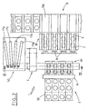
- the enclosed figures refer to articles 3, which are strip packages obtained from a continuous band 30 of welded blisters, cut longitudinally, which is cut by means 9 for crosswise cutting of the band 30, situated upstream of the inlet section A of the device 1 proposed by the invention.
- the crosswise cutting means 9 include two rolls, an upper roll and a lower roll, which are driven into rotation, in step relation with the feeding line 2, so as to release strip packages 3 to the inlet station A, mutually arranged in such a way, as to define a first configuration A1, in which they are set one beside another, coplanar and oriented along a substantially horizontal plane.
- the strip packages 3 are released to the inlet station A in a continuous way.
- the cutting means 9 are operated in accordance with signals coming from means 13 for detecting the moving step of the continuous band 30 of welded blisters.
- the receiving line 6, for feeding a boxing machine is situated angularly with respect to the feeding line 2, in particular it can be oriented longitudinally or crosswise thereto.
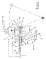
- the proposed device 1 includes an oscillating arm 4 having a plurality of gripping means 5, operated in step relation with the cutting means 9, to pick up strip packages 3 in the first configuration A1, in the region of the inlet station A, and to transfer them up to an outlet station B, where the strip packages 3 are released, arranged mutually in such a way, as to define a second configuration B1.
- the strip packages in the second configuration B1 have the same orientation as in the the first configuration A1, that is the packages are spaced apart and coplanar, oriented along a horizontal plane.
- the oscillating arm 4 transfers the strip packages 3 from the first configuration A1 to the second configuration B1, maintaining the same spatial arrangement thereof, along a horizontal plane.
- the outlet section B is situated at a slightly lower level with respect to the inlet station A, for example 50 mm lower.
- outlet section B can be situated substantially coplanar with or higher than the inlet station A.
- the device 1 proposed by the invention includes, at the outlet station B, a plurality of collecting compartments 7, which receive the strip packages 3 in the second configuration B1.
- the collecting compartments 7 have the bottoms substantially coplanar with the receiving line 6 and they are spaced apart by a fixed or variable distance corresponding to the distance between the seats 6a made in the receiving line 6.
- the gripping means 5 carried by the oscillating arm 4 cooperate with suitable guiding means 50, which vary uniformly the distance between the gripping means during the transition from the first configuration A1 to the second configuration B1, where the distance corresponds to the mutual spacing of the collecting compartments 7.
- the proposed device 1 includes, at the outlet station B, pusher means 8, operated in step relation with the oscillating arm 4, to convey the strip packages 3 situated in the collecting compartments 7 into the relative seats 6a made in the receiving line 6.
- the pusher means 8 are operated when the desired number of strip packages 3 are present inside the corresponding collecting compartments 7.
- a support member is situated at the inlet station A, to receive the strip packages 3 released by the cutting means 9.
- the support member moves from a waiting position H1, in which it supports the strip packages 3 in the first configuration A1, to an inclined position H2, in which it releases the strip packages 3 to a guiding channel 15 situated below and opening into a collecting container 11.
- the device 1 includes also deflecting means 12, which are connected to the guiding channel 15 and send the strip packages 3, released by the support member, into rooms 11a, 11b made in the collecting container 11.
- a first room 11a can receive empty and/or half-empty strip packages 3, that is with non-entire articles inside the blisters, while a second room 11b can receive entire strip packages 3, e.g. for samples test.
- the support member includes an oscillating plane 10 rotated by first driving means 10a, between the waiting position H1 and the inclined position H2, when enabled by means (not shown, since widely known), connected to the feeding line 2, for controlling and checking the entireness of the strip packages 3.
- the device 1 proposed by the present invention includes blowing means 14, situated near the inlet station A, operated in step relation with the cutting means 9 to send an air-jet to the strip packages 3 present in the inlet station A in the first configuration A1.
- the oscillating plane 10 carries a bearing plane 100 aimed at receiving strip packages 3 released from the feeding line 2, this bearing plate being operated by second driving means 100a, in step relation with the blowing means 14, to bring the strip packages 3 to the first configuration A1 near to the gripping means 5, against the action of the blowing means 14.
- the bearing plane 100 can reach a maximum excursion of 10 mm with respect to the oscillating plane 10, with the latter being in waiting position H1.
- the guiding means 50 include a plurality of curved cams 17a, 17b, 17c, 17d, aimed at interacting with the respective gripping means 5, so as to change the distance between the latter during the transition between the first configuration A1 and the second configuration B1.
- the gripping means 5 include corresponding control shafts 5a, 5b, 5c, 5d, having tubular shape, coaxial with one another, and carrying at one end suction means, which are connected to a source of vacuum, in step relation with the operation of the oscillating arm 4, and which have, at the other end, respective pins 50a, 50b, 50c, 50d, engaging with the corresponding curved cams 17a, 17b, 17c, 17d to cause longitudinal sliding of the tubular shafts 5a, 5b, 5c, 5d.
- the operation of the proposed device 1 will be described briefly by way of example, according to its second embodiment shown in Figure 5, with reference to a general operation step, in which the blowing means 14 are disabled and do not supply an air-jet, in which the gripping means 5 are waiting and disabled, that is they are not connected to the source of vacuum, at the inlet station A, and in which the oscillating plane 10 is in waiting position H1, with the bearing plane 100 set in contact with it.
- the feeding line 2 brings the leading end of the continuous band 30 of welded blisters to the inlet station A of the device 1.
- the blowing means 14 are enabled at that time, to maintain the continuous band 30 against the bearing plane 100, so as to avoid curving of the band upwards.
- the second activating means 100a operate the bearing plane 100, in step relation with activation of the blowing means 14, so as to bring the leading end of the continuous band 30, located at the inlet station A, to the gripping means 5, against the action of the blowing means 14.
- the gripping means 5 are then enabled, that is connected to the source of vacuum, in step relation with the movement of the bearing plane 100, so as to ensure the gripping of the leading end of the continuous band 30.
- the cutting means 9 cut the continuous band 30 crosswise, to define a plurality of strip packages 3 in the first configuration A1, in which they are arranged on a horizontal plane, one beside another and coplanar.
- the oscillating arm 4 transfers the strip packages 3 up to the outlet station B, releasing them inside the relative collecting compartments 7 in the second configuration B1, still coplanar but spaced crosswise.
- the driving shafts 5a, 5b, 5c, 5d engage with the relative pins 50a, 50b, 50c, 50d inside the corresponding curved cams 17a, 17b, 17c, 17d, thus causing the change of the distance between the gripping means 5, which in the outlet station B correspond to the distance defined by the collecting compartments 7.
- each collecting compartment 7 When a predetermined number of strip packages 3 is reached inside each collecting compartment 7, the pusher means 8 are operated to convey the strip packages 3 to the seats 6a made in the opposite receiving line 6.
- the first activating means 10a operate, in step relation with the cutting means 9, the transition of the oscillating plane 10, together with the associated bearing plane 100, in the inclined position H2, and the gripping means 5 are kept disabled, that is maintained disconnected from the vacuum source.
- the deflecting means 12 By operating suitably the deflecting means 12, this allows to collect the strip packages 3 checked as entire, in the prefixed second room 11b, to verify their effective entireness degree.
- the feeding line 2 brings the leading end of the continuous band 30 to the inlet station A, where it lies freely on the oscillating plane 10 in waiting position H.
- step relation with the feeding of the inlet station A the gripping means 5 are operated and the cutting means 9 cut crosswise the continuous band 30, to define a plurality of strip packages 3 in the first configuration A1.
- the oscillating arm 4 moves the strip packages 3 up to the outlet station B, into the relative collecting compartments 7, in which they are released in the second configuration B1.
- the proposed device can transfer articles, for example, strip packages, in controlled configuration, from a feeding line to a receiving line, situated angularly thereto, to feed a boxing machine.
- the receiving line can be oriented longitudinally (in line configuration) or crosswise (90° configuration) with respect to the feeding line.
- the proposed device allows to transfer articles (indifferently tablets, capsules, pills, or strip packages) in a controlled configuration into correspondingly dimensioned seats made in the receiving line, with the latter being in any configuration (in line or 90°), allowing the direct feeding of a boxing machine, without interposing any expensive apparatus.
- the proposed device can ensure high reliability and production rate standards in any operation conditions, and can be connected, in extremely rapid and intuitive way, to the outlet sections of any packaging machine, irrespective of the heights of the feeding line and of the receiving line.
Landscapes
- Engineering & Computer Science (AREA)
- Mechanical Engineering (AREA)
- Container Filling Or Packaging Operations (AREA)
- Auxiliary Devices For And Details Of Packaging Control (AREA)
- Branching, Merging, And Special Transfer Between Conveyors (AREA)
Claims (16)
- Vorrichtung zum Überführen von Gegenständen in einer gesteuerten Konfiguration von einem Zuführförderer zu einem Übernahmeförderer, insbesondere zum Beschicken einer Maschine zum Verpacken in Kisten, mit Einrichtungen (4) zum Hin- und Herbewegen, die Greifeinrichtungen (5) aufweisen, welche schrittweise mit dem Zuführförderer (2) betätigt werden, um Gegenstände (3) zu ergreifen, die so angeordnet sind, dass sie eine erste Konfiguration (A1) an einer Einlassstation (A) bilden, und die Gegenstände bis zu einer Auslassstation (B) zu überführen, in der sie so freigegeben werden, dass sie eine zweite Konfiguration (B1) der gleichen räumlichen Orientierung wie bei der ersten Konfiguration (A1) besitzen, einer Vielzahl von Sammelabteilen (7), die an der Auslassstation (B) angeordnet sind und deren Böden im wesentlichen koplanar zum Übernahmeförderer (6) angeordnet sind, um die Gegenstände (3) in der zweiten Konfiguration (B1) aufzunehmen, Führungseinrichtungen (50), die mit den Greifeinrichtungen (5) zusammenwirken, um die Distanz der Greifeinrichtungen während der Überführung von der ersten Konfiguration (A1) in die zweite Konfiguration (B1) gleichmäßig zu verändern, wobei diese Distanz dem Abstand der Sammelabteile (7) entspricht, und Drückereinrichtungen (8), die in der Auslassstation (B) angeordnet sind und schrittweise mit den Einrichtungen (4) zum Hin- und Herbewegen betätigt werden, um die in den Sammelabteilen (7) angeordneten Gegenstände (3) in Sitze (6a) zu befördern, die im Übernahmeförderer (6) ausgebildet sind.
- Vorrichtung nach Anspruch 1, dadurch gekennzeichnet, dass sie mindestens ein Lagerelement (10,100) aufweist, das in der Einlassstation (A) angeordnet ist, um vom Zuführförderer (2) freigegebene Gegenstände (3) aufzunehmen, wobei sich das Lagerelement von einer Warteposition (H1), in der es die Gegenstände (3) in der ersten Konfiguration (A1) lagert, in eine geneigte Position (H2) bewegt, in der es die Gegenstände (3) an einen Führungskanal (15) freigibt, der sich in mindestens einen Sammelbehälter (11) öffnet.
- Vorrichtung nach Anspruch 2, dadurch gekennzeichnet, dass sie Ablenkeinrichtungen (12) aufweist, die mit dem Führungskanal (15) verbunden sind und die vom Lagerelement (10,100) freigegebenen Gegenstände (3) in Räume (11a, 11b) des Sammelbehälters (11) schicken.
- Vorrichtung nach Anspruch 2 oder 3, dadurch gekennzeichnet, dass sie in der Nähe der Einlassstation (A) Blaseinrichtungen (14) umfasst, die schrittweise mit dem Zuführförderer (2) betätigt werden, um einen Luftstrahl auf die Gegenstände (3) auszustoßen, die in der Einlassstation (A) und in der ersten Konfiguration (A1) vorhanden sind, so dass diese im Wesentlichen koplanar gehalten werden und das Lagerelement (10,100) in der Warteposition (H1) berühren.
- Vorrichtung nach einem der Ansprüche 2 - 4, dadurch gekennzeichnet, dass das Lagerelement eine Schwingebene (10) aufweist, die zwischen der Warteposition (H1) und der geneigten Position (H2) über erste Antriebseinrichtungen (10a) betätigt wird, wenn sie von Einrichtungen in Kraft gesetzt wird, die mit dem Zuführförderer (2) verbunden sind, um die Vollständigkeit der Artikel (3) zu kontrollieren und zu überprüfen.
- Vorrichtung nach Anspruch 5, dadurch gekennzeichnet, dass das Lagerelement mindestens eine Lagerebene (100) aufweist, die von der Schwingebene (10) getragen wird und vom Zuführförderer (2) freigegebene Gegenstände (3) aufnimmt, wobei die Lagerebene (100) von zweiten Antriebseinrichtungen (100a) schrittweise mit den Blaseinrichtungen (14) betätigt wird, um die Gegenstände (3) in der ersten Konfiguration (A1) gegen die Wirkung der Blaseinrichtungen (14) zu den Greifeinrichtungen (5) zu bringen.
- Vorrichtung nach einem der vorangehenden Ansprüche, dadurch gekennzeichnet, dass sie Scheideinrichtungen (9) aufweist, die aufstromseitig der Eingangsstation (A) angeordnet sind und schrittweise mit dem Zuführförderer (2) betätigt werden, mit dem sie zusammenwirken, um die Gegenstände (3) der ersten Konfiguration (A1) zur Einlassstation (A) freizugeben.
- Vorrichtung nach Anspruch 7, dadurch gekennzeichnet, dass sie mit dem Zuführförderer (2) verbundene Einrichtungen (13) zum Detektieren des Überführungsschrittes der Gegenstände (3) aufweist, die mit den Schneideinrichtungen (9) zusammenwirken.
- Vorrichtung nach einem der vorangehenden Ansprüche, dadurch gekennzeichnet, dass die Führungseinrichtungen (50) eine Vielzahl von Nocken (17a,17b,17c,17d) aufweisen, die im wesentlichen gekrümmt sind und mit den Greifeinrichtungen (5) zusammenwirken, um die Distanz zwischen den Greifeinrichtungen während des Überganges zwischen der ersten Konfiguration (A1) und der zweiten Konfiguration (B1) zu verändern.
- Vorrichtung nach Anspruch 9, dadurch gekennzeichnet, dass die Greifeinrichtungen (5) entsprechende rohrförmige Antriebsschäfte (5a, 5b, 5c, 5d) aufweisen, die im wesentlichen koaxial zueinander angeordnet sind und an einem Ende Saugeinrichtungen, die bei Betätigung der Einrichtungen (4) zur Hin- und Herbewegung mit einer Unterdruckquelle verbunden werden, und am anderen Ende entsprechende Bolzen (50a,50b,50c,50d) aufweisen, die mit den gekrümmten Nocken (17a,17b,17c,17d) in Eingriff stehen, um die rohrförmigen Antriebsschäfte (5a,5b,5c, 5d) in Längsrichtung zum Gleiten zu bringen.
- Vorrichtung nach einem der Ansprüche 1 - 10, dadurch gekennzeichnet, dass die Einlassstation (A) niedriger angeordnet ist als die Auslassstation (B).
- Vorrichtung nach einem der Ansprüche 1 - 10, dadurch gekennzeichnet, dass die Einlassstation (A) höher angeordnet ist als die Auslassstation (B).
- Vorrichtung nach einem der Ansprüche 1 - 10, dadurch gekennzeichnet, dass die Einlassstation (A) im Wesentlichen koplanar mit der Auslassstation (B) angeordnet ist.
- Vorrichtung nach einem der vorangehenden Ansprüche, dadurch gekennzeichnet, dass der Übernahmeförderer (6) winklig zum Zuführförderer (2) angeordnet ist.
- Vorrichtung nach einem der vorangehenden Ansprüche, dadurch gekennzeichnet, dass der Übernahmeförderer (6) in Längsrichtung oder in Querrichtung zum Zuführförderer (2) angeordnet ist.
- Vorrichtung nach einem der vorangehenden Ansprüche, dadurch gekennzeichnet, dass der zuführförderer (2) Gegenstände (3) auf kontinuierliche Weise fördert.
Applications Claiming Priority (2)
| Application Number | Priority Date | Filing Date | Title |
|---|---|---|---|
| IT000753A ITBO20030753A1 (it) | 2003-12-16 | 2003-12-16 | Dispositivo per il trasferimento di articoli in configurazione |
| ITBO20030753 | 2003-12-16 |
Publications (2)
| Publication Number | Publication Date |
|---|---|
| EP1544110A1 EP1544110A1 (de) | 2005-06-22 |
| EP1544110B1 true EP1544110B1 (de) | 2007-11-07 |
Family
ID=34509422
Family Applications (1)
| Application Number | Title | Priority Date | Filing Date |
|---|---|---|---|
| EP04029624A Expired - Lifetime EP1544110B1 (de) | 2003-12-16 | 2004-12-15 | Vorrichtung zum Überführen von Gegenständen in einer gesteuerten Konfiguration von einem Zuführförderer zu einem Übernahmeförderer |
Country Status (5)
| Country | Link |
|---|---|
| US (1) | US7073312B2 (de) |
| EP (1) | EP1544110B1 (de) |
| DE (1) | DE602004009884T2 (de) |
| ES (1) | ES2295763T3 (de) |
| IT (1) | ITBO20030753A1 (de) |
Families Citing this family (28)
| Publication number | Priority date | Publication date | Assignee | Title |
|---|---|---|---|---|
| DE102004006375A1 (de) * | 2004-02-09 | 2005-09-15 | Uhlmann Pac-Systeme Gmbh & Co Kg | Verfahren und Vorrichtung zum Überführen von Produkten aus einem Vorratsgefäß in die Näpfe einer Folie |
| DE102004017288A1 (de) * | 2004-04-05 | 2005-10-20 | Iwk Verpackungstechnik Gmbh | Verfahren zur Handhabung eines Blisters in einer Blister-Verpackungsmaschine und Vorrichtung zur Durchführung des Verfahrens |
| DE102004043332A1 (de) * | 2004-09-08 | 2006-03-09 | Iwk Verpackungstechnik Gmbh | Verfahren zum Umsetzen eines Produktes in einer Verpackungsmaschine und Umsetzvorrichtung zur Durchführung des Verfahrens |
| DE102005057393A1 (de) * | 2005-11-30 | 2007-05-31 | Robert Bosch Gmbh | Wiegevorrichtung einer Verpackungsmaschine |
| US7540369B2 (en) * | 2005-12-19 | 2009-06-02 | Zoran Momich | Product handling system |
| EP1800645A1 (de) * | 2005-12-21 | 2007-06-27 | Körber AG | Verpackung für medizinische Produkte und dergleichen |
| ATE431311T1 (de) * | 2005-12-30 | 2009-05-15 | Cavanna Spa | Greiferkopf für eine warenüberführungseinrichtung und ein verfahren zum überführen von waren |
| JP5046632B2 (ja) * | 2006-12-12 | 2012-10-10 | 大和製衡株式会社 | 箱詰め装置 |
| ITBO20060899A1 (it) * | 2006-12-29 | 2008-06-30 | Marchesini Group Spa | Apparato per il riempimento di tubetti con pile di articoli di forma discoidale, quali compresse |
| ITBO20070178A1 (it) * | 2007-03-14 | 2008-09-15 | Marchesini Group Spa | Dispositivo per il prelievo di articoli da una stazione di alimentazione e per il deposito degli stessi in corrispondenti alveoli di un nastro alveolato |
| ITBO20070179A1 (it) * | 2007-03-14 | 2008-09-15 | Marchesini Group Spa | Dispositivo per il prelievo di articoli da una stazione di alimentazione e per l'inserimento degli stessi in un contenitore |
| ITBO20070592A1 (it) * | 2007-08-27 | 2009-02-28 | Marchesini Group Spa | Metodo per il riempimento degli alveoli di un nastro alveolato con corrispondenti articoli ed apparato che attua tale metodo |
| GB0812201D0 (en) * | 2008-07-04 | 2008-08-13 | Meadwestvaco Packaging Systems | Packaging machine and method therefor |
| IT1391405B1 (it) * | 2008-09-10 | 2011-12-23 | Fiordalba S R L | Metodo e dispositivo per la manipolazione di prodotti alimentari |
| DE102008063786A1 (de) | 2008-12-18 | 2010-07-01 | Romaco Pharmatechnik Gmbh | Vorrichtung zum Vereinzeln von Teilen |
| EP2228327A1 (de) * | 2009-03-13 | 2010-09-15 | Uhlmann Pac-Systeme GmbH & Co. KG | Vorrichtung zur Übergabe von Produkten |
| US8764367B2 (en) * | 2011-06-01 | 2014-07-01 | Stanley G. McCabe | Separator for articles of laundry |
| MX350790B (es) * | 2012-01-20 | 2017-09-19 | A & R Carton Lund Ab | Aparato y método para colocar una pala en un contenedor. |
| CN105398820B (zh) * | 2015-12-21 | 2017-12-22 | 苏州研高自动化科技有限公司 | 一种信号接头内白片上料装置 |
| ITUA20162281A1 (it) * | 2016-04-04 | 2017-10-04 | Gima Tt S P A | Dispositivo di trasferimento di gruppi organizzati di articoli da fumo, apparato e metodo per l'alimentazione e la formazione di gruppi organizzati di articoli da fumo comprendente detto dispositivo di trasferimento |
| CN106621236A (zh) * | 2016-12-23 | 2017-05-10 | 张家港久益机械有限公司 | 一种贴皮折边机自动下料装置 |
| EP3560846B1 (de) * | 2018-04-23 | 2024-08-07 | Uhlmann Pac-Systeme GmbH & Co. KG | Vorrichtung und verfahren zum transferieren von blisterpackungen |
| EP3560849B1 (de) * | 2018-04-23 | 2021-09-08 | Uhlmann Pac-Systeme GmbH & Co. KG | Übergabeeinheit und verfahren zum transferieren von blisterpackungen |
| CN111319966B (zh) * | 2018-12-13 | 2022-04-15 | 北京华文永康科技有限公司 | 一种设有激光检测控制的吸盘取碗装置 |
| CN111941131B (zh) * | 2020-08-11 | 2022-02-18 | 定远特尔润滚子有限公司 | 一种圆柱滚子自动加工装置 |
| IT202100000311A1 (it) * | 2021-01-11 | 2022-07-11 | Pharma Integration S R L | Dispositivo per spostare contenitori, apparato e metodo per produrre articoli farmaceutici o biotecnologici |
| CN115285428A (zh) * | 2022-08-04 | 2022-11-04 | 浙江诚达机械股份有限公司 | 一种转序输送机构 |
| IT202300027924A1 (it) * | 2023-12-22 | 2025-06-22 | Marchesini Group S P A | Dispositivo di trasferimento per trasferire prodotti da una prima linea di trasporto ad una seconda linea di trasporto |
Family Cites Families (13)
| Publication number | Priority date | Publication date | Assignee | Title |
|---|---|---|---|---|
| US3685624A (en) * | 1970-06-05 | 1972-08-22 | Paul F Paddock | Device to pack articles in boxes |
| DE2059461C3 (de) | 1970-06-20 | 1974-11-21 | Giovanni Mailand Carle (Italien) | Vorrichtung zum Behandeln von Süßwarenartikeln, insbes. von empfindlichen Schokoladeartikeln |
| IT1190555B (it) * | 1986-03-19 | 1988-02-16 | Ferrero Spa | Dispositivo di presa particolarmente per apparecchiature automatiche di sollevamento e trasporto di impianti per il confezionamento di prodotti alimentari |
| JPS6347264A (ja) | 1986-08-11 | 1988-02-29 | Yoshida Kogyo Kk <Ykk> | 長尺テ−プ状物の積重ね方法と装置 |
| DE8709053U1 (de) * | 1987-07-01 | 1987-09-10 | Fripack AG, Baar | Vorrichtung zum Gruppieren von Packungen |
| US4939891A (en) * | 1988-12-01 | 1990-07-10 | Piergiorgio Podini | Automatic baler for bundling together individual food bags previously filled in automatic packers |
| IT1271481B (it) * | 1993-10-11 | 1997-05-28 | Vortex Systems Srl | Dispositivo di manipolazione di prodotti e relativa apparecchiatura |
| US5611193A (en) * | 1995-01-31 | 1997-03-18 | Hudson Control Group, Inc. | Two-axis article loader/unloader |
| IT1286771B1 (it) | 1996-11-15 | 1998-07-17 | Ima Spa | Dispositivo per il trasferimento di blister da una stazione operativa ad una linea per il confezionamento dei medesimi blister in relativi |
| WO2000068086A1 (en) * | 1999-05-06 | 2000-11-16 | I.M.A. Industria Macchine Automatiche S.P.A. | Method and device for transferring blister packs from a cutting station to a blister packs conveying line |
| US6574943B2 (en) * | 2001-08-17 | 2003-06-10 | Blue Print Holding B.V. | Conveyor assembly for packagings, and method for delivery of a pack |
| ITBO20010713A1 (it) | 2001-11-23 | 2003-05-23 | Marchesini Group Spa | Metodo e dispositivo per il trasferimento di articoli , in particolare confezioni blister , alla linea di alimentazione di una macchina conf |
| ITBO20030075A1 (it) * | 2003-02-20 | 2004-08-21 | Packservice Srl | Stazione per la fornitura di articoli in configurazione |
-
2003
- 2003-12-16 IT IT000753A patent/ITBO20030753A1/it unknown
-
2004
- 2004-12-14 US US11/011,934 patent/US7073312B2/en not_active Expired - Lifetime
- 2004-12-15 ES ES04029624T patent/ES2295763T3/es not_active Expired - Lifetime
- 2004-12-15 EP EP04029624A patent/EP1544110B1/de not_active Expired - Lifetime
- 2004-12-15 DE DE602004009884T patent/DE602004009884T2/de not_active Expired - Lifetime
Also Published As
| Publication number | Publication date |
|---|---|
| ES2295763T3 (es) | 2008-04-16 |
| US7073312B2 (en) | 2006-07-11 |
| DE602004009884D1 (de) | 2007-12-20 |
| ITBO20030753A1 (it) | 2005-06-17 |
| US20050126115A1 (en) | 2005-06-16 |
| EP1544110A1 (de) | 2005-06-22 |
| DE602004009884T2 (de) | 2008-08-28 |
Similar Documents
| Publication | Publication Date | Title |
|---|---|---|
| EP1544110B1 (de) | Vorrichtung zum Überführen von Gegenständen in einer gesteuerten Konfiguration von einem Zuführförderer zu einem Übernahmeförderer | |
| US3934388A (en) | Method and apparatus for handling bags | |
| EP2544977B1 (de) | System und verfahren zum fördern von flaschen | |
| EP2915756A1 (de) | Verfahren und vorrichtung zur bereitstellung von beuteln | |
| US5827039A (en) | Apparatus for handling a stack of sheet-like products | |
| JP2014527796A (ja) | 角度付き移送チャンネルにロッド状物品の質量流を充填するためのバルブユニット | |
| EP1948511B1 (de) | Verfahren und vorrichtung zum füllen von behältern | |
| CN106687378A (zh) | 用于将袋进给到转盘的设备和方法 | |
| EP0648672A2 (de) | Stapelvorrichtung | |
| US20040068956A1 (en) | Case tab-lock slitting and flap sealer in combination with a continuous radial motion case packing apparatus and method | |
| EP1308388A1 (de) | Verfahren und Vorrichtung zum Transferieren von Blisterverpackungen und dergleichen von einer Schneideanlage zu einer Zuführlinie einer Verpackungsmaschine | |
| EP3494050B1 (de) | Verbesserte vorrichtung zum füllen von beuteln | |
| EP4403330A1 (de) | Harzzuführvorrichtung, harzformsystem und verfahren zur herstellung eines harzformartikels | |
| US7536842B2 (en) | Machine and a method for filling box-like containers with articles arranged side by side and vertically | |
| EP2103523A1 (de) | Verfahren und Einheit zur Bildung von Gruppen von Zwiebäcken oder ähnlichen Produkten | |
| CN210555779U (zh) | 一种用于瓶罐自动整理装箱的设备 | |
| CN110239765B (zh) | 一种用于瓶罐自动整理装箱的设备 | |
| CN222592475U (zh) | 一种自动输送上杯装置 | |
| WO2004089122A2 (en) | Cigarette transfer device | |
| EP1972557A1 (de) | Vorrichtung zur Positionierung von Schalen in Auslagekisten | |
| GB2341374A (en) | Article handling apparatus | |
| JP2566334B2 (ja) | コーンスリーブ装着装置 | |
| EP4662151A1 (de) | Vorrichtung und verfahren zum sortieren von zufallsgeprägten verschlusselementen unterschiedlicher art oder formate | |
| JPH09278003A (ja) | 充填装置 | |
| KR20030004295A (ko) | 봉투 속에 시이트를 삽입하기 위한 고속삽입기 |
Legal Events
| Date | Code | Title | Description |
|---|---|---|---|
| PUAI | Public reference made under article 153(3) epc to a published international application that has entered the european phase |
Free format text: ORIGINAL CODE: 0009012 |
|
| AK | Designated contracting states |
Kind code of ref document: A1 Designated state(s): AT BE BG CH CY CZ DE DK EE ES FI FR GB GR HU IE IS IT LI LT LU MC NL PL PT RO SE SI SK TR |
|
| AX | Request for extension of the european patent |
Extension state: AL BA HR LV MK YU |
|
| 17P | Request for examination filed |
Effective date: 20051212 |
|
| AKX | Designation fees paid |
Designated state(s): DE ES FR IT |
|
| GRAP | Despatch of communication of intention to grant a patent |
Free format text: ORIGINAL CODE: EPIDOSNIGR1 |
|
| GRAS | Grant fee paid |
Free format text: ORIGINAL CODE: EPIDOSNIGR3 |
|
| GRAA | (expected) grant |
Free format text: ORIGINAL CODE: 0009210 |
|
| AK | Designated contracting states |
Kind code of ref document: B1 Designated state(s): DE ES FR IT |
|
| REF | Corresponds to: |
Ref document number: 602004009884 Country of ref document: DE Date of ref document: 20071220 Kind code of ref document: P |
|
| REG | Reference to a national code |
Ref country code: ES Ref legal event code: FG2A Ref document number: 2295763 Country of ref document: ES Kind code of ref document: T3 |
|
| ET | Fr: translation filed | ||
| PLBE | No opposition filed within time limit |
Free format text: ORIGINAL CODE: 0009261 |
|
| STAA | Information on the status of an ep patent application or granted ep patent |
Free format text: STATUS: NO OPPOSITION FILED WITHIN TIME LIMIT |
|
| 26N | No opposition filed |
Effective date: 20080808 |
|
| REG | Reference to a national code |
Ref country code: DE Ref legal event code: R082 Ref document number: 602004009884 Country of ref document: DE Representative=s name: HAUCK PATENT- UND RECHTSANWAELTE, DE Ref country code: DE Ref legal event code: R082 Ref document number: 602004009884 Country of ref document: DE Representative=s name: HAUCK PATENTANWALTSPARTNERSCHAFT MBB, DE |
|
| REG | Reference to a national code |
Ref country code: FR Ref legal event code: PLFP Year of fee payment: 12 |
|
| REG | Reference to a national code |
Ref country code: FR Ref legal event code: PLFP Year of fee payment: 13 |
|
| REG | Reference to a national code |
Ref country code: FR Ref legal event code: PLFP Year of fee payment: 14 |
|
| PGFP | Annual fee paid to national office [announced via postgrant information from national office to epo] |
Ref country code: IT Payment date: 20231229 Year of fee payment: 20 Ref country code: FR Payment date: 20231219 Year of fee payment: 20 |
|
| PGFP | Annual fee paid to national office [announced via postgrant information from national office to epo] |
Ref country code: ES Payment date: 20240116 Year of fee payment: 20 |
|
| PGFP | Annual fee paid to national office [announced via postgrant information from national office to epo] |
Ref country code: DE Payment date: 20240119 Year of fee payment: 20 |
|
| P01 | Opt-out of the competence of the unified patent court (upc) registered |
Free format text: CASE NUMBER: APP_49829/2024 Effective date: 20240903 |
|
| REG | Reference to a national code |
Ref country code: DE Ref legal event code: R071 Ref document number: 602004009884 Country of ref document: DE |
|
| REG | Reference to a national code |
Ref country code: ES Ref legal event code: FD2A Effective date: 20241230 |
|
| PG25 | Lapsed in a contracting state [announced via postgrant information from national office to epo] |
Ref country code: ES Free format text: LAPSE BECAUSE OF EXPIRATION OF PROTECTION Effective date: 20241216 |
|
| PG25 | Lapsed in a contracting state [announced via postgrant information from national office to epo] |
Ref country code: ES Free format text: LAPSE BECAUSE OF EXPIRATION OF PROTECTION Effective date: 20241216 |