EP1544110B1 - Device for transferring articles in a controlled configuration from a feeding line to a receiving line - Google Patents
Device for transferring articles in a controlled configuration from a feeding line to a receiving line Download PDFInfo
- Publication number
- EP1544110B1 EP1544110B1 EP04029624A EP04029624A EP1544110B1 EP 1544110 B1 EP1544110 B1 EP 1544110B1 EP 04029624 A EP04029624 A EP 04029624A EP 04029624 A EP04029624 A EP 04029624A EP 1544110 B1 EP1544110 B1 EP 1544110B1
- Authority
- EP
- European Patent Office
- Prior art keywords
- articles
- configuration
- feeding line
- line
- station
- Prior art date
- Legal status (The legal status is an assumption and is not a legal conclusion. Google has not performed a legal analysis and makes no representation as to the accuracy of the status listed.)
- Active
Links
- 238000007664 blowing Methods 0.000 claims description 10
- 230000007704 transition Effects 0.000 claims description 6
- 238000011144 upstream manufacturing Methods 0.000 claims description 2
- 238000004806 packaging method and process Methods 0.000 description 6
- 230000004913 activation Effects 0.000 description 3
- 230000003213 activating effect Effects 0.000 description 2
- 238000009434 installation Methods 0.000 description 2
- 238000012423 maintenance Methods 0.000 description 2
- 238000004519 manufacturing process Methods 0.000 description 2
- 239000002775 capsule Substances 0.000 description 1
- 239000006187 pill Substances 0.000 description 1
- 238000005070 sampling Methods 0.000 description 1
- 239000003826 tablet Substances 0.000 description 1
Images


Classifications
-
- B—PERFORMING OPERATIONS; TRANSPORTING
- B65—CONVEYING; PACKING; STORING; HANDLING THIN OR FILAMENTARY MATERIAL
- B65B—MACHINES, APPARATUS OR DEVICES FOR, OR METHODS OF, PACKAGING ARTICLES OR MATERIALS; UNPACKING
- B65B35/00—Supplying, feeding, arranging or orientating articles to be packaged
- B65B35/30—Arranging and feeding articles in groups
- B65B35/54—Feeding articles along multiple paths to a single packaging position
-
- B—PERFORMING OPERATIONS; TRANSPORTING
- B65—CONVEYING; PACKING; STORING; HANDLING THIN OR FILAMENTARY MATERIAL
- B65B—MACHINES, APPARATUS OR DEVICES FOR, OR METHODS OF, PACKAGING ARTICLES OR MATERIALS; UNPACKING
- B65B35/00—Supplying, feeding, arranging or orientating articles to be packaged
- B65B35/30—Arranging and feeding articles in groups
- B65B35/36—Arranging and feeding articles in groups by grippers
- B65B35/38—Arranging and feeding articles in groups by grippers by suction-operated grippers
-
- B—PERFORMING OPERATIONS; TRANSPORTING
- B65—CONVEYING; PACKING; STORING; HANDLING THIN OR FILAMENTARY MATERIAL
- B65B—MACHINES, APPARATUS OR DEVICES FOR, OR METHODS OF, PACKAGING ARTICLES OR MATERIALS; UNPACKING
- B65B35/00—Supplying, feeding, arranging or orientating articles to be packaged
- B65B35/30—Arranging and feeding articles in groups
- B65B35/40—Arranging and feeding articles in groups by reciprocating or oscillatory pushers
- B65B35/405—Arranging and feeding articles in groups by reciprocating or oscillatory pushers linked to endless conveyors
-
- B—PERFORMING OPERATIONS; TRANSPORTING
- B65—CONVEYING; PACKING; STORING; HANDLING THIN OR FILAMENTARY MATERIAL
- B65B—MACHINES, APPARATUS OR DEVICES FOR, OR METHODS OF, PACKAGING ARTICLES OR MATERIALS; UNPACKING
- B65B35/00—Supplying, feeding, arranging or orientating articles to be packaged
- B65B35/30—Arranging and feeding articles in groups
- B65B35/50—Stacking one article, or group of articles, upon another before packaging
-
- B—PERFORMING OPERATIONS; TRANSPORTING
- B65—CONVEYING; PACKING; STORING; HANDLING THIN OR FILAMENTARY MATERIAL
- B65B—MACHINES, APPARATUS OR DEVICES FOR, OR METHODS OF, PACKAGING ARTICLES OR MATERIALS; UNPACKING
- B65B57/00—Automatic control, checking, warning, or safety devices
- B65B57/10—Automatic control, checking, warning, or safety devices responsive to absence, presence, abnormal feed, or misplacement of articles or materials to be packaged
- B65B57/14—Automatic control, checking, warning, or safety devices responsive to absence, presence, abnormal feed, or misplacement of articles or materials to be packaged and operating to control, or stop, the feed of articles or material to be packaged
-
- B—PERFORMING OPERATIONS; TRANSPORTING
- B65—CONVEYING; PACKING; STORING; HANDLING THIN OR FILAMENTARY MATERIAL
- B65G—TRANSPORT OR STORAGE DEVICES, e.g. CONVEYORS FOR LOADING OR TIPPING, SHOP CONVEYOR SYSTEMS OR PNEUMATIC TUBE CONVEYORS
- B65G47/00—Article or material-handling devices associated with conveyors; Methods employing such devices
- B65G47/74—Feeding, transfer, or discharging devices of particular kinds or types
- B65G47/90—Devices for picking-up and depositing articles or materials
- B65G47/91—Devices for picking-up and depositing articles or materials incorporating pneumatic, e.g. suction, grippers
- B65G47/914—Devices for picking-up and depositing articles or materials incorporating pneumatic, e.g. suction, grippers provided with drive systems incorporating rotary and rectilinear movements
Definitions
- the present invention relates to automatic packaging of articles in general, for example the so-called strip packages, envelopes and the like.
- the present invention relates to a device for transferring articles in a controlled configuration from a feeding line to a receiving line, the latter being connected to a boxing machine.
- a device of this kind is known from WO-A-00/68086
- the common problem lies in adjusting the configuration of the articles released by the packaging machine to the distance between the seats of the receiving line, which are dimensioned in relation to the articles size.
- Another problem relates to adapting the height of the outlet of the articles released by the packaging machine to the height imposed by the receiving line for feeding the boxing machine.
- the object of the present invention is to propose a device for transferring articles in a controlled configuration from a feeding line to a receiving line, which device is capable of supplying articles in a controlled configurations, varying within a wide range, to any boxing machine, in a particularly flexible and efficient way.
- Another object of the present invention is to propose a device which is extremely functional and reliable and which supplies articles in a controlled configurations independently from the heights of the corresponding lines, feeding and receiving lines, and from the operation modes, continuous or stepwise, of the feeding line.
- a further object of the present invention is to propose a particularly compact device, whose installation and maintenance are especially simple and easy.
- a still further object of the present invention is to propose a device, which ensures high production rates in any operation conditions, and which can be connected in cascade to any packaging machine in an extremely rapid and intuitive way.
- general reference numeral 1 indicates the proposed device for transferring articles 3 in a controlled configuration from a feeding line 2 to a receiving line 6, in particular for feeding a boxing machine.
- the enclosed figures refer to articles 3, which are strip packages obtained from a continuous band 30 of welded blisters, cut longitudinally, which is cut by means 9 for crosswise cutting of the band 30, situated upstream of the inlet section A of the device 1 proposed by the invention.
- the crosswise cutting means 9 include two rolls, an upper roll and a lower roll, which are driven into rotation, in step relation with the feeding line 2, so as to release strip packages 3 to the inlet station A, mutually arranged in such a way, as to define a first configuration A1, in which they are set one beside another, coplanar and oriented along a substantially horizontal plane.
- the strip packages 3 are released to the inlet station A in a continuous way.
- the cutting means 9 are operated in accordance with signals coming from means 13 for detecting the moving step of the continuous band 30 of welded blisters.
- the receiving line 6, for feeding a boxing machine is situated angularly with respect to the feeding line 2, in particular it can be oriented longitudinally or crosswise thereto.
- the proposed device 1 includes an oscillating arm 4 having a plurality of gripping means 5, operated in step relation with the cutting means 9, to pick up strip packages 3 in the first configuration A1, in the region of the inlet station A, and to transfer them up to an outlet station B, where the strip packages 3 are released, arranged mutually in such a way, as to define a second configuration B1.
- the strip packages in the second configuration B1 have the same orientation as in the the first configuration A1, that is the packages are spaced apart and coplanar, oriented along a horizontal plane.
- the oscillating arm 4 transfers the strip packages 3 from the first configuration A1 to the second configuration B1, maintaining the same spatial arrangement thereof, along a horizontal plane.
- the outlet section B is situated at a slightly lower level with respect to the inlet station A, for example 50 mm lower.
- outlet section B can be situated substantially coplanar with or higher than the inlet station A.
- the device 1 proposed by the invention includes, at the outlet station B, a plurality of collecting compartments 7, which receive the strip packages 3 in the second configuration B1.
- the collecting compartments 7 have the bottoms substantially coplanar with the receiving line 6 and they are spaced apart by a fixed or variable distance corresponding to the distance between the seats 6a made in the receiving line 6.
- the gripping means 5 carried by the oscillating arm 4 cooperate with suitable guiding means 50, which vary uniformly the distance between the gripping means during the transition from the first configuration A1 to the second configuration B1, where the distance corresponds to the mutual spacing of the collecting compartments 7.
- the proposed device 1 includes, at the outlet station B, pusher means 8, operated in step relation with the oscillating arm 4, to convey the strip packages 3 situated in the collecting compartments 7 into the relative seats 6a made in the receiving line 6.
- the pusher means 8 are operated when the desired number of strip packages 3 are present inside the corresponding collecting compartments 7.
- a support member is situated at the inlet station A, to receive the strip packages 3 released by the cutting means 9.
- the support member moves from a waiting position H1, in which it supports the strip packages 3 in the first configuration A1, to an inclined position H2, in which it releases the strip packages 3 to a guiding channel 15 situated below and opening into a collecting container 11.
- the device 1 includes also deflecting means 12, which are connected to the guiding channel 15 and send the strip packages 3, released by the support member, into rooms 11a, 11b made in the collecting container 11.
- a first room 11a can receive empty and/or half-empty strip packages 3, that is with non-entire articles inside the blisters, while a second room 11b can receive entire strip packages 3, e.g. for samples test.
- the support member includes an oscillating plane 10 rotated by first driving means 10a, between the waiting position H1 and the inclined position H2, when enabled by means (not shown, since widely known), connected to the feeding line 2, for controlling and checking the entireness of the strip packages 3.
- the device 1 proposed by the present invention includes blowing means 14, situated near the inlet station A, operated in step relation with the cutting means 9 to send an air-jet to the strip packages 3 present in the inlet station A in the first configuration A1.
- the oscillating plane 10 carries a bearing plane 100 aimed at receiving strip packages 3 released from the feeding line 2, this bearing plate being operated by second driving means 100a, in step relation with the blowing means 14, to bring the strip packages 3 to the first configuration A1 near to the gripping means 5, against the action of the blowing means 14.
- the bearing plane 100 can reach a maximum excursion of 10 mm with respect to the oscillating plane 10, with the latter being in waiting position H1.
- the guiding means 50 include a plurality of curved cams 17a, 17b, 17c, 17d, aimed at interacting with the respective gripping means 5, so as to change the distance between the latter during the transition between the first configuration A1 and the second configuration B1.
- the gripping means 5 include corresponding control shafts 5a, 5b, 5c, 5d, having tubular shape, coaxial with one another, and carrying at one end suction means, which are connected to a source of vacuum, in step relation with the operation of the oscillating arm 4, and which have, at the other end, respective pins 50a, 50b, 50c, 50d, engaging with the corresponding curved cams 17a, 17b, 17c, 17d to cause longitudinal sliding of the tubular shafts 5a, 5b, 5c, 5d.
- the operation of the proposed device 1 will be described briefly by way of example, according to its second embodiment shown in Figure 5, with reference to a general operation step, in which the blowing means 14 are disabled and do not supply an air-jet, in which the gripping means 5 are waiting and disabled, that is they are not connected to the source of vacuum, at the inlet station A, and in which the oscillating plane 10 is in waiting position H1, with the bearing plane 100 set in contact with it.
- the feeding line 2 brings the leading end of the continuous band 30 of welded blisters to the inlet station A of the device 1.
- the blowing means 14 are enabled at that time, to maintain the continuous band 30 against the bearing plane 100, so as to avoid curving of the band upwards.
- the second activating means 100a operate the bearing plane 100, in step relation with activation of the blowing means 14, so as to bring the leading end of the continuous band 30, located at the inlet station A, to the gripping means 5, against the action of the blowing means 14.
- the gripping means 5 are then enabled, that is connected to the source of vacuum, in step relation with the movement of the bearing plane 100, so as to ensure the gripping of the leading end of the continuous band 30.
- the cutting means 9 cut the continuous band 30 crosswise, to define a plurality of strip packages 3 in the first configuration A1, in which they are arranged on a horizontal plane, one beside another and coplanar.
- the oscillating arm 4 transfers the strip packages 3 up to the outlet station B, releasing them inside the relative collecting compartments 7 in the second configuration B1, still coplanar but spaced crosswise.
- the driving shafts 5a, 5b, 5c, 5d engage with the relative pins 50a, 50b, 50c, 50d inside the corresponding curved cams 17a, 17b, 17c, 17d, thus causing the change of the distance between the gripping means 5, which in the outlet station B correspond to the distance defined by the collecting compartments 7.
- each collecting compartment 7 When a predetermined number of strip packages 3 is reached inside each collecting compartment 7, the pusher means 8 are operated to convey the strip packages 3 to the seats 6a made in the opposite receiving line 6.
- the first activating means 10a operate, in step relation with the cutting means 9, the transition of the oscillating plane 10, together with the associated bearing plane 100, in the inclined position H2, and the gripping means 5 are kept disabled, that is maintained disconnected from the vacuum source.
- the deflecting means 12 By operating suitably the deflecting means 12, this allows to collect the strip packages 3 checked as entire, in the prefixed second room 11b, to verify their effective entireness degree.
- the feeding line 2 brings the leading end of the continuous band 30 to the inlet station A, where it lies freely on the oscillating plane 10 in waiting position H.
- step relation with the feeding of the inlet station A the gripping means 5 are operated and the cutting means 9 cut crosswise the continuous band 30, to define a plurality of strip packages 3 in the first configuration A1.
- the oscillating arm 4 moves the strip packages 3 up to the outlet station B, into the relative collecting compartments 7, in which they are released in the second configuration B1.
- the proposed device can transfer articles, for example, strip packages, in controlled configuration, from a feeding line to a receiving line, situated angularly thereto, to feed a boxing machine.
- the receiving line can be oriented longitudinally (in line configuration) or crosswise (90° configuration) with respect to the feeding line.
- the proposed device allows to transfer articles (indifferently tablets, capsules, pills, or strip packages) in a controlled configuration into correspondingly dimensioned seats made in the receiving line, with the latter being in any configuration (in line or 90°), allowing the direct feeding of a boxing machine, without interposing any expensive apparatus.
- the proposed device can ensure high reliability and production rate standards in any operation conditions, and can be connected, in extremely rapid and intuitive way, to the outlet sections of any packaging machine, irrespective of the heights of the feeding line and of the receiving line.
Description
- The present invention relates to automatic packaging of articles in general, for example the so-called strip packages, envelopes and the like.
- In this specific case, the present invention relates to a device for transferring articles in a controlled configuration from a feeding line to a receiving line, the latter being connected to a boxing machine. A device of this kind is known from
WO-A-00/68086 - One of the most frequently reported necessities in the technical field concerned is the possibility of transferring the articles released by a packaging machine, in a controlled configuration, to a receiving line connected to a boxing machine.
- The common problem lies in adjusting the configuration of the articles released by the packaging machine to the distance between the seats of the receiving line, which are dimensioned in relation to the articles size.
- Another problem relates to adapting the height of the outlet of the articles released by the packaging machine to the height imposed by the receiving line for feeding the boxing machine.
- If the articles are obtained by cutting from a continuous strip, as in case of the so-called strip packages, there is another problem connected with possible curving of the strip near the cutting means.
- The object of the present invention is to propose a device for transferring articles in a controlled configuration from a feeding line to a receiving line, which device is capable of supplying articles in a controlled configurations, varying within a wide range, to any boxing machine, in a particularly flexible and efficient way.
- Another object of the present invention is to propose a device which is extremely functional and reliable and which supplies articles in a controlled configurations independently from the heights of the corresponding lines, feeding and receiving lines, and from the operation modes, continuous or stepwise, of the feeding line.
- A further object of the present invention is to propose a particularly compact device, whose installation and maintenance are especially simple and easy.
- A still further object of the present invention is to propose a device, which ensures high production rates in any operation conditions, and which can be connected in cascade to any packaging machine in an extremely rapid and intuitive way.
- The above mentioned objects are obtained in accordance with the contents of the claims.
- The characteristic features of the invention will be pointed out in the following description of some preferred but not exclusive embodiments, with reference to the enclosed figures, in which:
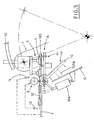
- Figure 1 is a schematic, lateral view of the device proposed by the invention, according to a particular embodiment, in some extremely significant operation steps;
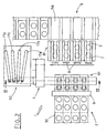
- Figure 2 is a schematic, top view of the device shown in Figure 1;
- Figure 3a is a schematic, enlarged section view taken along the III-III of Figure 2 in a first operation step;
- Figure 3b is a schematic, further enlarged section view taken along the same III-III of Figure 2, in a second operation step;
- Figure 4 is a schematic, section view, taken along IV-IV of Figure 3a;
- Figure 5 is a schematic, lateral, enlarged view of the device shown in Figure 1, according to another embodiment.
- With reference to the above Figures, general reference numeral 1 indicates the proposed device for transferring
articles 3 in a controlled configuration from afeeding line 2 to areceiving line 6, in particular for feeding a boxing machine. - As a mere example, the enclosed figures refer to
articles 3, which are strip packages obtained from acontinuous band 30 of welded blisters, cut longitudinally, which is cut bymeans 9 for crosswise cutting of theband 30, situated upstream of the inlet section A of the device 1 proposed by the invention. - In known way, the crosswise cutting means 9 include two rolls, an upper roll and a lower roll, which are driven into rotation, in step relation with the
feeding line 2, so as to releasestrip packages 3 to the inlet station A, mutually arranged in such a way, as to define a first configuration A1, in which they are set one beside another, coplanar and oriented along a substantially horizontal plane. - Advantageously, according to a preferred but not unique embodiment, the
strip packages 3 are released to the inlet station A in a continuous way. - In particular, in known way, the cutting means 9 are operated in accordance with signals coming from
means 13 for detecting the moving step of thecontinuous band 30 of welded blisters. - The
receiving line 6, for feeding a boxing machine, is situated angularly with respect to thefeeding line 2, in particular it can be oriented longitudinally or crosswise thereto. - Advantageously, the proposed device 1 includes an
oscillating arm 4 having a plurality of gripping means 5, operated in step relation with thecutting means 9, to pick upstrip packages 3 in the first configuration A1, in the region of the inlet station A, and to transfer them up to an outlet station B, where thestrip packages 3 are released, arranged mutually in such a way, as to define a second configuration B1. - The strip packages in the second configuration B1 have the same orientation as in the the first configuration A1, that is the packages are spaced apart and coplanar, oriented along a horizontal plane.
- In a known way, the oscillating
arm 4 transfers thestrip packages 3 from the first configuration A1 to the second configuration B1, maintaining the same spatial arrangement thereof, along a horizontal plane. - In the proposed embodiments, the outlet section B is situated at a slightly lower level with respect to the inlet station A, for example 50 mm lower.
- This does not exclude that the outlet section B can be situated substantially coplanar with or higher than the inlet station A.
- The device 1 proposed by the invention includes, at the outlet station B, a plurality of collecting
compartments 7, which receive thestrip packages 3 in the second configuration B1. - The
collecting compartments 7 have the bottoms substantially coplanar with thereceiving line 6 and they are spaced apart by a fixed or variable distance corresponding to the distance between the seats 6a made in thereceiving line 6. - The gripping means 5 carried by the oscillating
arm 4 cooperate withsuitable guiding means 50, which vary uniformly the distance between the gripping means during the transition from the first configuration A1 to the second configuration B1, where the distance corresponds to the mutual spacing of thecollecting compartments 7. - The proposed device 1 includes, at the outlet station B, pusher means 8, operated in step relation with the oscillating
arm 4, to convey thestrip packages 3 situated in the collectingcompartments 7 into the relative seats 6a made in thereceiving line 6. - The pusher means 8 are operated when the desired number of
strip packages 3 are present inside thecorresponding collecting compartments 7. - A support member is situated at the inlet station A, to receive the
strip packages 3 released by thecutting means 9. The support member moves from a waiting position H1, in which it supports thestrip packages 3 in the first configuration A1, to an inclined position H2, in which it releases thestrip packages 3 to a guidingchannel 15 situated below and opening into acollecting container 11. - The device 1 includes also deflecting
means 12, which are connected to the guidingchannel 15 and send thestrip packages 3, released by the support member, intorooms container 11. - For example, a
first room 11a can receive empty and/or half-empty strip packages 3, that is with non-entire articles inside the blisters, while asecond room 11b can receiveentire strip packages 3, e.g. for samples test. - With particular reference to Figure 1, according to a first embodiment, the support member includes an
oscillating plane 10 rotated by first driving means 10a, between the waiting position H1 and the inclined position H2, when enabled by means (not shown, since widely known), connected to thefeeding line 2, for controlling and checking the entireness of thestrip packages 3. - With particular reference to Figure 5, related to a second embodiment, the device 1 proposed by the present invention includes
blowing means 14, situated near the inlet station A, operated in step relation with thecutting means 9 to send an air-jet to thestrip packages 3 present in the inlet station A in the first configuration A1. - The oscillating
plane 10 carries abearing plane 100 aimed at receivingstrip packages 3 released from thefeeding line 2, this bearing plate being operated by second driving means 100a, in step relation with theblowing means 14, to bring thestrip packages 3 to the first configuration A1 near to the gripping means 5, against the action of the blowingmeans 14. - For example, the
bearing plane 100 can reach a maximum excursion of 10 mm with respect to the oscillatingplane 10, with the latter being in waiting position H1. - With particular reference to Figures 2, 3a, 3b and 4, the guiding
means 50 include a plurality ofcurved cams - The gripping means 5 include
corresponding control shafts arm 4, and which have, at the other end,respective pins curved cams tubular shafts - Now, the operation of the proposed device 1 will be described briefly by way of example, according to its second embodiment shown in Figure 5, with reference to a general operation step, in which the blowing
means 14 are disabled and do not supply an air-jet, in which the gripping means 5 are waiting and disabled, that is they are not connected to the source of vacuum, at the inlet station A, and in which the oscillatingplane 10 is in waiting position H1, with thebearing plane 100 set in contact with it. - The
feeding line 2 brings the leading end of thecontinuous band 30 of welded blisters to the inlet station A of the device 1. - The
blowing means 14 are enabled at that time, to maintain thecontinuous band 30 against thebearing plane 100, so as to avoid curving of the band upwards. - The second activating means 100a operate the
bearing plane 100, in step relation with activation of theblowing means 14, so as to bring the leading end of thecontinuous band 30, located at the inlet station A, to the gripping means 5, against the action of theblowing means 14. - The gripping means 5 are then enabled, that is connected to the source of vacuum, in step relation with the movement of the
bearing plane 100, so as to ensure the gripping of the leading end of thecontinuous band 30. - In step relation with the above activation, the cutting means 9 cut the
continuous band 30 crosswise, to define a plurality ofstrip packages 3 in the first configuration A1, in which they are arranged on a horizontal plane, one beside another and coplanar. - In step relation with the activation of the cutting means 9, the oscillating
arm 4 transfers thestrip packages 3 up to the outlet station B, releasing them inside therelative collecting compartments 7 in the second configuration B1, still coplanar but spaced crosswise. - During the oscillating
arm 4 movement, thedriving shafts relative pins curved cams collecting compartments 7. - When a predetermined number of
strip packages 3 is reached inside eachcollecting compartment 7, the pusher means 8 are operated to convey thestrip packages 3 to the seats 6a made in theopposite receiving line 6. - If the means for checking the entireness of the articles present in the welded blisters of the
continuous band 30 find anomalies, for example empty blisters or not entire articles, the first activating means 10a operate, in step relation with thecutting means 9, the transition of theoscillating plane 10, together with the associatedbearing plane 100, in the inclined position H2, and the gripping means 5 are kept disabled, that is maintained disconnected from the vacuum source. - This allows to convey the
strip packages 3 into the guidingchannel 15 and, by suitably operating thedeflecting means 12, to send subsequently thestrip packages 3 to the prefixedfirst room 11a, aimed at receiving theempty strip packages 3, and/or half-empty, that is with non-entire articles therein. - In a general operation step of the device 1 proposed by the invention, it is possible to control by sampling the
strip packages 3, by operating forcedly the transition of the oscillatingplane 10 to the inclined position H2, independently from the signal coming from the means for control and check of the articles entireness. - By operating suitably the deflecting means 12, this allows to collect the
strip packages 3 checked as entire, in the prefixedsecond room 11b, to verify their effective entireness degree. - The working way of the device 1 in its first embodiment (Figure 1, 2) derives clearly from what has been written above with reference to the second embodiment (Figure 5).
- Actually, in this case, the
feeding line 2 brings the leading end of thecontinuous band 30 to the inlet station A, where it lies freely on the oscillatingplane 10 in waiting position H. - In step relation with the feeding of the inlet station A, the gripping means 5 are operated and the cutting means 9 cut crosswise the
continuous band 30, to define a plurality ofstrip packages 3 in the first configuration A1. - Then, the oscillating
arm 4 moves thestrip packages 3 up to the outlet station B, into therelative collecting compartments 7, in which they are released in the second configuration B1. - From what above, it is understood how the proposed device can transfer articles, for example, strip packages, in controlled configuration, from a feeding line to a receiving line, situated angularly thereto, to feed a boxing machine.
- Actually, in relation to the machine desired layout, the receiving line can be oriented longitudinally (in line configuration) or crosswise (90° configuration) with respect to the feeding line.
- The proposed device allows to transfer articles (indifferently tablets, capsules, pills, or strip packages) in a controlled configuration into correspondingly dimensioned seats made in the receiving line, with the latter being in any configuration (in line or 90°), allowing the direct feeding of a boxing machine, without interposing any expensive apparatus.
- In case of articles deriving from the cutting of a continuous band, as in case of strip packages, it is suitable to use the second embodiment, which solves easily the problems connected with possible curving of the band near the cutting means, which is extremely difficult in case of continuous feeding of the band.
- Consequently, the proposed device can ensure high reliability and production rate standards in any operation conditions, and can be connected, in extremely rapid and intuitive way, to the outlet sections of any packaging machine, irrespective of the heights of the feeding line and of the receiving line.
- The extreme constructive simplicity and best compactness of the proposed device ensures particularly simple and easy installation and maintenance operations.
Claims (16)
- Device for transferring articles in a controlled configuration from a feeding line to a receiving line, in particular for feeding a boxing machine, which includes: oscillating means (4) having gripping means (5), operated in step relation with said feeding line (2), to pick up articles (3) arranged mutually in such a way, as to define a first configuration (A1), at an inlet station (A), and to transfer them up to an outlet station (B), where the articles (3) are released, arranged mutually in such a way, as to define a second configuration (B1) having the same spatial orientation as said first configuration (A1); a plurality of collecting compartments (7), situated at said outlet station (B), with the bottoms substantially coplanar with respect to said receiving line (6) for receiving said articles (3) in said second configuration (B1); guiding means (50), cooperating with said gripping means (5) for changing uniformly the distance of said gripping means during the transition from said first configuration (A1) to said second configuration (B1), where the distance corresponds to the mutual spacing of said collecting compartments (7); pusher means (8), situated in said outlet station (B), operated in step relation with said oscillating means (4) for conveying the articles (3) positioned in said collecting compartments (7) into seats (6a) made in said receiving line (6).
- Device, as claimed in claim 1, characterized in that it includes at least one support member (10, 100), which is situated in said inlet station (A) for receiving articles (3) released by said feeding line (2), said support member moving from a waiting position (H1), in which it supports the articles (3) in said first configuration (A1), to an inclined position (H2), in which it releases said articles (3) to a guiding channel (15) opening into at least one collecting container (11).
- Device, as claimed in claim 2, characterized in that it includes deflecting means (12), which are connected to said guiding channel (15) and which send said articles (3) released by said support member (10,100) into rooms (11a, 11b) of said collecting container (11).
- Device, as claimed in claim 2 or 3, characterized in that it includes, near said inlet station (A), blowing means (14), operated in step relation with said feeding line (2) for ejecting an air-jet onto the articles (3) present in said inlet station (A) in said first configuration (A1), so as to maintain them substantially coplanar and touching said support member (10, 100) in said waiting position (H1).
- Device, as claimed in one of claims from 2 to 4, characterized in that said support member includes an oscillating plane (10), operated between said positions, waiting position (H1) and inclined position (H2), by first driving means (10a), when enabled by means, connected to said feeding line (2) for controlling and checking the entireness of the articles (3).
- Device, as claimed in claim 5, characterized in that said support member includes at least one bearing plane (100), carried by said oscillating plane (10) and receiving articles (3) released by said feeding line (2), said bearing plane (100) being operated by second driving means (100a), in step relation with said blowing means (14), to bring said articles (3) in first configuration (A1) to said gripping means (5), against the action of the blowing means (14).
- Device, as claimed in any of the previous claims, characterized in that it includes cutting means (9), situated upstream of said inlet station (A), operated in step relation with the feeding line (2), with which it cooperates to release the articles (3) in said first configuration (A1) to said inlet station (A).
- Device, as claimed in claim 7, characterized in that it includes means (13), connected to said feeding line (2) for detecting the transfer step of said articles (3) and interacting with said cutting means (9).
- Device, as claimed in any of the previous claims, characterized in that said guiding means (50) include a plurality of cams (17a, 17b, 17c, 17d), substantially curved, interacting with said gripping means (5), so as to change the distance between the gripping means during the transition between said first configuration (A1) and said second configuration (B1).
- Device, as claimed in claim 9, characterized in that said gripping means (5) include corresponding tubular driving shafts (5a, 5b, 5c, 5d), in substantial coaxial relation with one another, which carry, at one end suction means connected, when said oscillating means (4) are operated, to a vacuum source, and having, at the other end, respective pins (50a, 50b, 50c, 50d), which engage with said curved cams (17a, 17b, 17c, 17d), to make said tubular driving shafts (5a, 5b, 5c, 5d) slide longitudinally.
- Device, as claimed in any of the claims from 1 to 10, characterized in that said inlet station (A) is situated lower than said outlet station (B).
- Device, as claimed in any of the claims from 1 to 10, characterized in that said inlet station (A) is situated higher than said outlet station (B).
- Device, as claimed in any of the claims from 1 to 10, characterized in that said inlet station (A) is substantially coplanar with said outlet station (B).
- Device, as claimed in any of the previous claims, characterized in that it includes said receiving line (6) arranged angularly with respect to said feeding line (2).
- Device, as claimed in any of the previous claims, characterized in that it includes said receiving line (6) arranged longitudinally or crosswise with respect to said feeding line (2).
- Device, as claimed in any of the previous claims, characterized in that said feeding line (2) feeds articles (3) in a continuous way.
Applications Claiming Priority (2)
| Application Number | Priority Date | Filing Date | Title |
|---|---|---|---|
| ITBO20030753 | 2003-12-16 | ||
| IT000753A ITBO20030753A1 (en) | 2003-12-16 | 2003-12-16 | DEVICE FOR TRANSFER OF ARTICLES IN CONFIGURATION |
Publications (2)
| Publication Number | Publication Date |
|---|---|
| EP1544110A1 EP1544110A1 (en) | 2005-06-22 |
| EP1544110B1 true EP1544110B1 (en) | 2007-11-07 |
Family
ID=34509422
Family Applications (1)
| Application Number | Title | Priority Date | Filing Date |
|---|---|---|---|
| EP04029624A Active EP1544110B1 (en) | 2003-12-16 | 2004-12-15 | Device for transferring articles in a controlled configuration from a feeding line to a receiving line |
Country Status (5)
| Country | Link |
|---|---|
| US (1) | US7073312B2 (en) |
| EP (1) | EP1544110B1 (en) |
| DE (1) | DE602004009884T2 (en) |
| ES (1) | ES2295763T3 (en) |
| IT (1) | ITBO20030753A1 (en) |
Families Citing this family (26)
| Publication number | Priority date | Publication date | Assignee | Title |
|---|---|---|---|---|
| DE102004006375A1 (en) * | 2004-02-09 | 2005-09-15 | Uhlmann Pac-Systeme Gmbh & Co Kg | Method and device for transferring products from a storage vessel into the wells of a film |
| DE102004017288A1 (en) * | 2004-04-05 | 2005-10-20 | Iwk Verpackungstechnik Gmbh | A method for handling a blister in a blister packaging machine and apparatus for carrying out the method |
| DE102004043332A1 (en) * | 2004-09-08 | 2006-03-09 | Iwk Verpackungstechnik Gmbh | Method of reacting a product in a packaging machine and transfer device for carrying out the method |
| DE102005057393A1 (en) * | 2005-11-30 | 2007-05-31 | Robert Bosch Gmbh | Weighing device e.g. intermittent capsule filling machine for filling a product to be dosed into capsule, has first and second weighing device whereby second weighing device which detects net weight of capsule |
| US7540369B2 (en) * | 2005-12-19 | 2009-06-02 | Zoran Momich | Product handling system |
| EP1800645A1 (en) * | 2005-12-21 | 2007-06-27 | Körber AG | Package for medicinal products and the like |
| ES2324920T3 (en) * | 2005-12-30 | 2009-08-19 | Cavanna S.P.A. | PRESS HEAD FOR A PRODUCT TRANSFER DEVICE AND PROCEDURE FOR PRODUCT TRANSFER. |
| JP5046632B2 (en) * | 2006-12-12 | 2012-10-10 | 大和製衡株式会社 | Boxing equipment |
| ITBO20060899A1 (en) * | 2006-12-29 | 2008-06-30 | Marchesini Group Spa | APPARATUS FOR FILLING TUBES WITH BATTERIES OF DISCOIDAL-SHAPED ARTICLES, WHICH ARE TABLETS |
| ITBO20070179A1 (en) * | 2007-03-14 | 2008-09-15 | Marchesini Group Spa | DEVICE FOR THE COLLECTION OF ITEMS FROM A POWER STATION AND FOR INSERTING THEMSELVES INTO A CONTAINER |
| ITBO20070178A1 (en) * | 2007-03-14 | 2008-09-15 | Marchesini Group Spa | DEVICE FOR THE COLLECTION OF ITEMS FROM A POWER STATION AND TO STORE THEMSELVES IN CORRESPONDING ALVEOLI OF A HOLLOWED TAPE |
| ITBO20070592A1 (en) * | 2007-08-27 | 2009-02-28 | Marchesini Group Spa | METHOD FOR FILLING THE HOLLOWS OF A HOLLOWED TAPE WITH CORRESPONDING ARTICLES AND APPARATUS THAT ACTIVES THIS METHOD |
| GB0812201D0 (en) * | 2008-07-04 | 2008-08-13 | Meadwestvaco Packaging Systems | Packaging machine and method therefor |
| IT1391405B1 (en) * | 2008-09-10 | 2011-12-23 | Fiordalba S R L | METHOD AND DEVICE FOR THE MANIPULATION OF FOOD PRODUCTS |
| DE102008063786A1 (en) * | 2008-12-18 | 2010-07-01 | Romaco Pharmatechnik Gmbh | Device for separating parts |
| EP2228327A1 (en) * | 2009-03-13 | 2010-09-15 | Uhlmann Pac-Systeme GmbH & Co. KG | Device for delivery of products |
| US8764367B2 (en) * | 2011-06-01 | 2014-07-01 | Stanley G. McCabe | Separator for articles of laundry |
| JP6043811B2 (en) * | 2012-01-20 | 2016-12-14 | オーアンドアール・カートン・ルンド・アーベー | Apparatus and method for placing an insulator in a container |
| CN105398820B (en) * | 2015-12-21 | 2017-12-22 | 苏州研高自动化科技有限公司 | White tiles feeding device in a kind of Signal connector |
| ITUA20162281A1 (en) * | 2016-04-04 | 2017-10-04 | Gima Tt S P A | TRANSFER OF ORGANIZED GROUPS OF SMOKE ITEMS, APPARATUS AND METHOD FOR THE SUPPLY AND TRAINING OF ORGANIZED GROUPS OF SMOKE ARTICLES INCLUDING THE TRANSFER DEVICE |
| CN106621236A (en) * | 2016-12-23 | 2017-05-10 | 张家港久益机械有限公司 | Automatic blanking device of surface folding flanging machine |
| EP3560849B1 (en) * | 2018-04-23 | 2021-09-08 | Uhlmann Pac-Systeme GmbH & Co. KG | Transfer unit and method for transferring blister packs |
| EP3560846A1 (en) * | 2018-04-23 | 2019-10-30 | UHLMANN PAC-SYSTEME GmbH & Co. KG | Method and device for transferring blister packs |
| CN111319966B (en) * | 2018-12-13 | 2022-04-15 | 北京华文永康科技有限公司 | Sucking disc bowl taking device with laser detection control function |
| CN111941131B (en) * | 2020-08-11 | 2022-02-18 | 定远特尔润滚子有限公司 | Automatic processing device for cylindrical roller |
| CN115285428A (en) * | 2022-08-04 | 2022-11-04 | 浙江诚达机械股份有限公司 | Order-changing conveying mechanism |
Family Cites Families (13)
| Publication number | Priority date | Publication date | Assignee | Title |
|---|---|---|---|---|
| US3685624A (en) * | 1970-06-05 | 1972-08-22 | Paul F Paddock | Device to pack articles in boxes |
| DE2059461C3 (en) | 1970-06-20 | 1974-11-21 | Giovanni Mailand Carle (Italien) | Device for treating confectionery articles, in particular sensitive chocolate articles |
| IT1190555B (en) * | 1986-03-19 | 1988-02-16 | Ferrero Spa | GRIPPING DEVICE ESPECIALLY FOR AUTOMATIC LIFTING AND TRANSPORT EQUIPMENT FOR PACKAGING FOOD PRODUCTS |
| JPS6347264A (en) | 1986-08-11 | 1988-02-29 | Yoshida Kogyo Kk <Ykk> | Stacking method for lengthy tape-shaped object and its device |
| DE8709053U1 (en) * | 1987-07-01 | 1987-09-10 | Kvm Kontroll- Und Verpackungsmaschinen Gmbh & Co Kg, 7131 Wurmberg, De | |
| US4939891A (en) * | 1988-12-01 | 1990-07-10 | Piergiorgio Podini | Automatic baler for bundling together individual food bags previously filled in automatic packers |
| IT1271481B (en) * | 1993-10-11 | 1997-05-28 | Vortex Systems Srl | PRODUCT HANDLING DEVICE AND RELATED EQUIPMENT |
| US5611193A (en) * | 1995-01-31 | 1997-03-18 | Hudson Control Group, Inc. | Two-axis article loader/unloader |
| IT1286771B1 (en) | 1996-11-15 | 1998-07-17 | Ima Spa | DEVICE FOR THE TRANSFER OF BLISTERS FROM AN OPERATING STATION TO A LINE FOR THE PACKAGING OF THE SAME BLISTERS IN RELATIVE |
| EP1094968B1 (en) * | 1999-05-06 | 2004-10-20 | I.M.A. Industria Macchine Automatiche S.p.A. | Method and device for transferring blister packs from a cutting station to a blister packs conveying line |
| US6574943B2 (en) * | 2001-08-17 | 2003-06-10 | Blue Print Holding B.V. | Conveyor assembly for packagings, and method for delivery of a pack |
| ITBO20010713A1 (en) | 2001-11-23 | 2003-05-23 | Marchesini Group Spa | METHOD AND DEVICE FOR THE TRANSFER OF ITEMS, IN PARTICULAR BLISTER PACKS, TO THE SUPPLY LINE OF A CONF MACHINE |
| ITBO20030075A1 (en) * | 2003-02-20 | 2004-08-21 | Packservice Srl | STATION FOR THE SUPPLY OF CONFIGURATION ITEMS |
-
2003
- 2003-12-16 IT IT000753A patent/ITBO20030753A1/en unknown
-
2004
- 2004-12-14 US US11/011,934 patent/US7073312B2/en active Active
- 2004-12-15 ES ES04029624T patent/ES2295763T3/en active Active
- 2004-12-15 DE DE602004009884T patent/DE602004009884T2/en active Active
- 2004-12-15 EP EP04029624A patent/EP1544110B1/en active Active
Also Published As
| Publication number | Publication date |
|---|---|
| DE602004009884T2 (en) | 2008-08-28 |
| DE602004009884D1 (en) | 2007-12-20 |
| EP1544110A1 (en) | 2005-06-22 |
| ITBO20030753A1 (en) | 2005-06-17 |
| US20050126115A1 (en) | 2005-06-16 |
| ES2295763T3 (en) | 2008-04-16 |
| US7073312B2 (en) | 2006-07-11 |
Similar Documents
| Publication | Publication Date | Title |
|---|---|---|
| EP1544110B1 (en) | Device for transferring articles in a controlled configuration from a feeding line to a receiving line | |
| US3934388A (en) | Method and apparatus for handling bags | |
| EP1948511B1 (en) | Method and device for fillling containers | |
| CN1899143B (en) | A method and equipment for batch handling and transfer of tobacco products | |
| EP2544977B1 (en) | Bottle feeding system and method | |
| EP2915756A1 (en) | Bag supply method and device | |
| KR102418304B1 (en) | A device and method for feeding pouches to a carousel | |
| JP2014527796A (en) | Valve unit for filling a mass flow of rod-shaped articles into an angled transfer channel | |
| US5827039A (en) | Apparatus for handling a stack of sheet-like products | |
| EP0648672A2 (en) | Collating apparatus | |
| KR101997576B1 (en) | Multi-cutting system for pipe forming machine | |
| EP3494050B1 (en) | Enhanced apparatus for filling bags | |
| CN115402584A (en) | Bag feeding packaging machine and bag feeding packaging method | |
| EP1848637A1 (en) | A machine and a method for filling box-like containers with articles arranged side by side and vertically | |
| EP1308388B1 (en) | Method and device for transferring blister packs and the like from a cutting station to a feeding line of a packaging machine | |
| CN212345277U (en) | Cigarette automatic feeding device | |
| CN100564162C (en) | Be used to pack the equipment of container rigidity, that an end opens wide | |
| CN210555779U (en) | Equipment for automatically arranging and boxing bottles and cans | |
| EP2103523A1 (en) | Method and unit for forming groups of rusks or similar products | |
| CN217775436U (en) | Wire rod processing equipment | |
| EP1972557A1 (en) | A positioning device for arranging trays in crates | |
| WO2023042509A1 (en) | Resin supply apparatus, resin molding system, and method for producing resin molded article | |
| GB2341374A (en) | Article handling apparatus | |
| CN208068847U (en) | A kind of plastic cup formation rack with Manipulator Transportation device | |
| JP2566334B2 (en) | Cone sleeve mounting device |
Legal Events
| Date | Code | Title | Description |
|---|---|---|---|
| PUAI | Public reference made under article 153(3) epc to a published international application that has entered the european phase |
Free format text: ORIGINAL CODE: 0009012 |
|
| AK | Designated contracting states |
Kind code of ref document: A1 Designated state(s): AT BE BG CH CY CZ DE DK EE ES FI FR GB GR HU IE IS IT LI LT LU MC NL PL PT RO SE SI SK TR |
|
| AX | Request for extension of the european patent |
Extension state: AL BA HR LV MK YU |
|
| 17P | Request for examination filed |
Effective date: 20051212 |
|
| AKX | Designation fees paid |
Designated state(s): DE ES FR IT |
|
| GRAP | Despatch of communication of intention to grant a patent |
Free format text: ORIGINAL CODE: EPIDOSNIGR1 |
|
| GRAS | Grant fee paid |
Free format text: ORIGINAL CODE: EPIDOSNIGR3 |
|
| GRAA | (expected) grant |
Free format text: ORIGINAL CODE: 0009210 |
|
| AK | Designated contracting states |
Kind code of ref document: B1 Designated state(s): DE ES FR IT |
|
| REF | Corresponds to: |
Ref document number: 602004009884 Country of ref document: DE Date of ref document: 20071220 Kind code of ref document: P |
|
| REG | Reference to a national code |
Ref country code: ES Ref legal event code: FG2A Ref document number: 2295763 Country of ref document: ES Kind code of ref document: T3 |
|
| ET | Fr: translation filed | ||
| PLBE | No opposition filed within time limit |
Free format text: ORIGINAL CODE: 0009261 |
|
| STAA | Information on the status of an ep patent application or granted ep patent |
Free format text: STATUS: NO OPPOSITION FILED WITHIN TIME LIMIT |
|
| 26N | No opposition filed |
Effective date: 20080808 |
|
| REG | Reference to a national code |
Ref country code: DE Ref legal event code: R082 Ref document number: 602004009884 Country of ref document: DE Representative=s name: HAUCK PATENTANWALTSPARTNERSCHAFT MBB, DE Ref country code: DE Ref legal event code: R082 Ref document number: 602004009884 Country of ref document: DE Representative=s name: HAUCK PATENT- UND RECHTSANWAELTE, DE |
|
| REG | Reference to a national code |
Ref country code: FR Ref legal event code: PLFP Year of fee payment: 12 |
|
| REG | Reference to a national code |
Ref country code: FR Ref legal event code: PLFP Year of fee payment: 13 |
|
| REG | Reference to a national code |
Ref country code: FR Ref legal event code: PLFP Year of fee payment: 14 |
|
| PGFP | Annual fee paid to national office [announced via postgrant information from national office to epo] |
Ref country code: ES Payment date: 20230116 Year of fee payment: 19 |
|
| PGFP | Annual fee paid to national office [announced via postgrant information from national office to epo] |
Ref country code: DE Payment date: 20230117 Year of fee payment: 19 |
|
| PGFP | Annual fee paid to national office [announced via postgrant information from national office to epo] |
Ref country code: IT Payment date: 20231229 Year of fee payment: 20 Ref country code: FR Payment date: 20231219 Year of fee payment: 20 |