EP1544021A2 - Zuluftkanal für einen Kühler - Google Patents
Zuluftkanal für einen Kühler Download PDFInfo
- Publication number
- EP1544021A2 EP1544021A2 EP04024453A EP04024453A EP1544021A2 EP 1544021 A2 EP1544021 A2 EP 1544021A2 EP 04024453 A EP04024453 A EP 04024453A EP 04024453 A EP04024453 A EP 04024453A EP 1544021 A2 EP1544021 A2 EP 1544021A2
- Authority
- EP
- European Patent Office
- Prior art keywords
- luftführungshutze
- air duct
- supply air
- duct according
- opening
- Prior art date
- Legal status (The legal status is an assumption and is not a legal conclusion. Google has not performed a legal analysis and makes no representation as to the accuracy of the status listed.)
- Granted
Links
Images



Classifications
-
- B—PERFORMING OPERATIONS; TRANSPORTING
- B60—VEHICLES IN GENERAL
- B60K—ARRANGEMENT OR MOUNTING OF PROPULSION UNITS OR OF TRANSMISSIONS IN VEHICLES; ARRANGEMENT OR MOUNTING OF PLURAL DIVERSE PRIME-MOVERS IN VEHICLES; AUXILIARY DRIVES FOR VEHICLES; INSTRUMENTATION OR DASHBOARDS FOR VEHICLES; ARRANGEMENTS IN CONNECTION WITH COOLING, AIR INTAKE, GAS EXHAUST OR FUEL SUPPLY OF PROPULSION UNITS IN VEHICLES
- B60K11/00—Arrangement in connection with cooling of propulsion units
- B60K11/08—Air inlets for cooling; Shutters or blinds therefor
Definitions
- the invention relates to a supply air duct for a radiator of a vehicle gem. the Preamble of claim 1.
- Such a supply air duct is known from DE 199 26 862 C2 and comprises a Air duct hood and a subsequent flow channel.
- the Luft arrangement the Heileshutze from outside into the opening of the Body shell part used.
- Locally provided at the Heileshutze Fixation noses should be doing on a second step-shaped impression of the Support body shell part, so that circumferentially a constant gap between the edge of the Vietnamese arrangementhutze and the body shell part is achieved.
- the double stepped embossing on the edge area of the opening of the Body shell part is in several successive steps produced. In the area of the second step-shaped impression, therefore, relatively high levels occur Tolerances on, so that a constant circumferential gap between the edge the air duct hood and the body shell part only by an elevated Can be displayed assembly work or by rework.
- the object of the invention is to provide a fastening concept for the Luft enclosureshutze and / or to provide the flow channel, with the independent of teaching and workers always a constant position of Heil arrangementhutze and / or the flow channel is guaranteed relative to the body shell part.
- the rear area of a vehicle 1 shown in FIG. 1 comprises side doors 2, a fixed body outer skin part 3 arranged behind, wheels 4, Rear lighting units 5 and an outer trim part 6 for a not closer shown bumper.
- the cowling 6 is with side sections 7 to adjacent rear wheel arches 8 introduced.
- each vehicle longitudinal side is a supply air duct 9 for a not closer provided intercooler provided.
- the supply air duct has at its air inlet side 10 is an air guide cover used in an opening 11 of the body shell part 3 12 and an adjoining closed flow channel 13. The exit the guided through the intercooler air takes place on the cowling 6th arranged side exit slots 14.
- the body shell part 3 is in Embodiment formed by a rear side part.
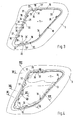
- the opening 11 Adjacent to the rear edge 15 of the door 2 and slightly below the belt line 16 is formed on the body outer skin part 3, the opening 11, which is approximately a quadrangular Has basic shape with rounded transition areas between the individual pages.
- a front side 17 of the opening 11 extends in regions parallel to the rear edge 15 the door, while a rear side 18 is slightly flattened.
- a top 19 and a bottom 20 of the opening 11 are slightly opposite to a horizontal auxiliary plane tilted backwards to the top.
- the Beer arrangementshutze 12 is from the vehicle outside inserted into the opening 11 of the body shell part 3, wherein the ships arrangementshutze 12 via a circumferential collar portion 21 at a second outer stepped embossment 22 of the body shell part 3 is supported.
- Collar portion 21 is a projecting into the underlying body cavity Stub portion 23 led away, wherein the nozzle portion 23 in the embodiment via an approximately horizontally extending rib 24 in two superimposed sections is divided.
- the Beer arrangementhutze 12 may also have more or fewer ribs 24, which also can be arranged vertically or obliquely.
- the flow passage 13 is at the inner side 25 of the body outer skin part 3 and introduced adjacent to the Opening 11 on an end-side annular frame member 26 which has a circumferential Sealing body 27 receives (Fig. 6 and 7).
- each two spaced rectangular cut-out plates 29, 30th provided, which are punched out in the manufacture of the body shell part 3.
- the outer edges 33, 33 'of the trim tabs 29, 30 serve as a receptacle for the Throughflow 13
- the inner edges 34, 34 'of the trim tabs 29, 30th serve as a receptacle for the Beer arrangementshutze 12.
- the projecting positioning 31 associated with the Luft enclosureshutze 12, each Positioning pin 31 with two spaced inner edges 34, 34 'of Trim tabs 29, 30 and the intermediate reason of the recording interacts positively.
- each two spaced-apart positioning sections 32 are formed, which with the outer edges 33, 33 'of the two trim tabs 29, 30 positively cooperate (Fig. 3 to 6).
- the trim tabs 29, 30 at the top and bottom 19, 20 each extend in the vertical direction, whereas the trim tabs 29, 30 at the front 17 of the Opening 11 are aligned horizontally.
- the vertical trimming tabs 29, 30 is carried out in each case a positioning in the X direction, whereas the horizontal aligned trim tabs 29, 30 cause a positioning in the Z direction. Due to the support in the Y direction, the two-time determination in the X direction and the additional positioning in the Z direction are set all degrees of freedom and the Components 12, 13 are clearly positioned.
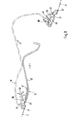
- the inner flow channel 13 is via a plurality of detachable connections, preferably Screws 35 attached to the body shell part 3 (Fig. 9). These are in Attachment areas of the flow channel 13 at the edge of the opening 11 of the Body outer skin part 3 projecting retaining tabs 36 with a passage opening 37th intended.
- a threaded nut or a metal nut 38 plugged into the vehicle from the outside a Fixing screw 39 can be screwed.
- the Beer arrangement 12 consists of an outer air inlet panel 40 and a circumferential inner support frame 41. Both components 40, 41 are not closer in one shown teaching glued together in the correct position.
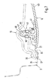
- a hidden fastening concept for the Vietnamese arrangementshutze 12 is achieved by that these at least one spring element 42 and at least one detachable Locking connection 43 is held in position (Fig. 7 and 8).
- these at least one spring element 42 and at least one detachable Locking connection 43 is held in position (Fig. 7 and 8).
- two superimposed arranged spring elements 42 are provided, which with a resilient inner Support legs 45 under prestressing on the adjacent flow channel 13.
- the Spring elements 42 are provided with U-shaped mounting portions on the free end of the inner holding frame 41 attached.
- the inner support frame 41 engages behind a front edge region of the flow-through channel 13 (FIG. 8).
- the retaining clips 48 are of the Vehicle outside forth in recesses 49 of the end-side frame part 26 of the Throughflow channels 13 are used and have two parked inwardly projecting Retaining tongues 50, which with the locking lugs 47 of the Lucas arrangementhutze 12 clamping interact (Fig. 7).
Landscapes
- Engineering & Computer Science (AREA)
- Chemical & Material Sciences (AREA)
- Combustion & Propulsion (AREA)
- Transportation (AREA)
- Mechanical Engineering (AREA)
- Air-Conditioning For Vehicles (AREA)
- Cooling, Air Intake And Gas Exhaust, And Fuel Tank Arrangements In Propulsion Units (AREA)
- Vehicle Step Arrangements And Article Storage (AREA)
Abstract
Description
- Fig. 1
- eine Teilansicht auf einen Personenkraftwagen mit einer in eine Öffnung eines Karosserieaußenhautteils eingesetzten Luftführungshutze eines Zuluftkanals für einen Kühler,
- Fig. 2
- eine Einzelheit X der Fig. 1 in größerer Darstellung,
- Fig. 3
- eine Teilseitenansicht auf das Karosserieaußenhautteil mit der vorgesehenen Öffnung, jedoch ohne eingesetzte Luftführungshutze und ohne Durchströmkanal,
- Fig. 4
- eine Teilseitenansicht auf das Karosserieaußenhautteil mit dem eingesetzten Durchströmkanal,
- Fig. 5
- eine Ansicht von innen auf das Karosserieaußenhautteil mit der eingesetzten Luftführungshutze,
- Fig. 6
- einen Schnitt nach der Linie VI-VI der Figur 4 in größerer Darstellung,
- Fig. 7
- einen Schnitt nach der Linie VII-VII der Figur 4 in größerer Darstellung,
- Fig. 8
- einen Schnitt nach der Linie VIII-VIII der Figur 4 in größerer Darstellung
- Fig. 9
- einen Schnitt nach der Linie IX-IX der Fig. 4 in größerer Darstellung.
Claims (11)
- Zuluftkanal für einen Kühler eines Fahrzeuges, der an seiner Lufteintrittsseite eine in eine Öffnung eines Karosserieaußenhautteiles eingesetzte und sich über einen umlaufenden Kragenabschnitt an der Außenseite des Karosserieaußenhautteils abgestützte Luftführungshutze aufweist, wobei vom äußeren Kragenabschnitt der Luftführungshutze ein in den dahinterliegenden Karosseriehohlraum ragender Stutzenabschnitt weggeführt ist und dass die Luftführungshutze an einen angrenzenden geschlossenen Durchströmkanal angeschlossen ist, dadurch gekennzeichnet, dass am Rand(28) der Öffnung (11) mehrere paarweise angeordnete, in die Öffnung (11) hineinragende Beschnittlaschen (29, 30) vorgesehen sind, die mit Positionierzapfen (31) bzw. Positionierabschnitten (32) der Luftführungshutze (12) und/oder des Durchströmkanals (13) formschlüssig zusammenwirken.
- Zuluftkanal nach Anspruch 1, dadurch gekennzeichnet, dass an einer Oberseite (19), einer Unterseite (20) und an einer Vorderseite (17) der Öffnung (11) jeweils zwei beabstandet angeordnete rechteckförmige Beschnittlaschen (29, 30) vorgesehen sind.
- Zuluftkanal nach den Ansprüchen 1 und 2, dadurch gekennzeichnet, dass die äußeren Kanten (33, 33') der Beschnittlaschen (29, 30) als Aufnahme für den Durchströmkanal (13) dienen, wogegen die inneren Kanten (34, 34') der Beschnittlaschen (29, 30) als Aufnahme für die Luftführungshutze (12) dienen.
- Zuluftkanal nach einem der vorangegangenen Ansprüche, dadurch gekennzeichnet, dass an der Luftführungshutze (12) vorstehende Positionierzapfen (31) angeformt sind, die bei montierter Luftführungshutze (12) mit der durch die inneren Kanten (34, 34') der beabstandeten Beschnittlaschen (29, 30) gebildeten Aufnahme formschlüssig zusammenwirken.
- Zuluftkanal nach einem der vorangegangenen Ansprüche, dadurch gekennzeichnet, dass am Durchströmkanal (13) im Bereich der Beschnittlaschen (29, 30) jeweils zwei beabstandet angeordnete Positionierabschnitte (32) vorgesehen sind, die mit den äußeren Kanten (33, 33') der Beschnittlaschen (29, 30) formschlüssig zusammenwirken.
- Zuluftkanal nach einem der vorangegangenen Ansprüche, dadurch gekennzeichnet, dass der innere Durchströmkanal (13) über lösbare Verbindungen (z.B. Schraubverbindungen) am Karosserieaußenhautteil (3) befestigt ist.
- Zuluftkanal nach Anspruch 6, dadurch gekennzeichnet, dass in Befestigungsbereichen für den Durchströmkanal (13) randseitig an der Öffnung (11) des Karosserieaußenhauteils (3) Haltelaschen (36) mit jeweils einer Durchtrittsöffnung (37) ausgebildet sind, wobei auf jede Haltelasche (36) eine Gewindemutter (38) aufsteckbar ist, in die eine Befestigungsschraube (39) zum Festlegen des Durchströmkanals (13) eindrehbar ist.
- Zuluftkanal nach einem der vorangegangenen Ansprüche, dadurch gekennzeichnet, dass die äußere Luftführungshutze (12) über zumindest ein Federelement (42) mit dem Karosserieaußenhautteil (3) zusammenwirkt.
- Zuluftkanal nach einem der vorangegangenen Ansprüche, dadurch gekennzeichnet, dass die äußere Luftführungshutze (12) über lösbare Rastverbindungen (43) mit dem inneren Durchströmkanal (13) verbunden ist.
- Zuluftkanal nach einem der vorangegangenen Ansprüche, dadurch gekennzeichnet, dass die Luftführungshutze (12) aus einer äußeren Lufteinlassblende (40) und einem inneren umlaufenden Halterahmen (41) besteht, wobei beide Teile in einer Lehre lagerichtig miteinander verklebt sind.
- Zuluftkanal nach einem der vorangegangenen Ansprüche, dadurch gekennzeichnet, dass am Halterahmen (41) örtliche angeformte Stege (46) mit endseitigen Rastnasen (47) vorgesehen sind, die mit Halteklammern (48) des Durchströmkanals (13) verrastend zusammenwirken.
Applications Claiming Priority (2)
| Application Number | Priority Date | Filing Date | Title |
|---|---|---|---|
| DE10359769A DE10359769B3 (de) | 2003-12-19 | 2003-12-19 | Zuluftkanal für einen Kühler |
| DE10359769 | 2003-12-19 |
Publications (3)
| Publication Number | Publication Date |
|---|---|
| EP1544021A2 true EP1544021A2 (de) | 2005-06-22 |
| EP1544021A3 EP1544021A3 (de) | 2005-12-28 |
| EP1544021B1 EP1544021B1 (de) | 2008-03-05 |
Family
ID=34485499
Family Applications (1)
| Application Number | Title | Priority Date | Filing Date |
|---|---|---|---|
| EP04024453A Expired - Lifetime EP1544021B1 (de) | 2003-12-19 | 2004-10-14 | Zuluftkanal für einen Kühler |
Country Status (4)
| Country | Link |
|---|---|
| US (1) | US7163073B2 (de) |
| EP (1) | EP1544021B1 (de) |
| JP (1) | JP4092327B2 (de) |
| DE (2) | DE10359769B3 (de) |
Cited By (1)
| Publication number | Priority date | Publication date | Assignee | Title |
|---|---|---|---|---|
| EP4015274A1 (de) * | 2020-12-14 | 2022-06-22 | REHAU Automotive SE & Co. KG | Luftführungsvorrichtung für ein kraftfahrzeug, aussenhautbauteil für ein kraftfahrzeug sowie verfahren zum herstellen eines solchen aussenhautbauteils |
Families Citing this family (22)
| Publication number | Priority date | Publication date | Assignee | Title |
|---|---|---|---|---|
| JP2005324609A (ja) * | 2004-05-12 | 2005-11-24 | Toyota Motor Corp | レゾネータの取付構造 |
| JP4847073B2 (ja) * | 2005-08-29 | 2011-12-28 | ヤンマー株式会社 | トラクタ |
| US20070068717A1 (en) * | 2005-09-27 | 2007-03-29 | Austin James B | Hidden fastening system for motor vehicle instrument panels |
| JP4283326B1 (ja) * | 2007-12-25 | 2009-06-24 | 本田技研工業株式会社 | バッテリの冷却風取入構造 |
| DE102008006103B4 (de) | 2008-01-25 | 2017-12-28 | Dr. Ing. H.C. F. Porsche Aktiengesellschaft | Kraftfahrzeug |
| US8011465B2 (en) | 2008-11-13 | 2011-09-06 | International Truck Intellectual Property Company, Llc | Air intake plenum for air induction channel |
| DE102008060410B4 (de) | 2008-11-28 | 2023-08-31 | Dr. Ing. H.C. F. Porsche Aktiengesellschaft | Kraftfahrzeug mit Schwellerblende |
| GB2476279B (en) * | 2009-12-17 | 2016-05-25 | Gordon Murray Design Ltd | Vehicle comprising a rearwardly mounted engine and radiator |
| DE102010007633A1 (de) * | 2010-02-05 | 2011-08-11 | Dr. Ing. h.c. F. Porsche Aktiengesellschaft, 70435 | Fahrzeug mit elektrischer Antriebsvorrichtung |
| DE102011000210B4 (de) * | 2011-01-19 | 2021-03-25 | Dr. Ing. H.C. F. Porsche Aktiengesellschaft | Kraftfahrzeugaufbau |
| DE102011078691B4 (de) * | 2011-07-05 | 2026-03-26 | Röchling Automotive SE | Luftleiteinrichtung für ein Kraftfahrzeug |
| US8708075B2 (en) * | 2012-01-16 | 2014-04-29 | Honda Motor Co., Ltd. | Front end structure for vehicle |
| CA2779475C (en) * | 2012-05-29 | 2015-04-07 | Macdon Industries Ltd. | Windrower tractor with parallel heat exchangers for cooling of engine and associated fluids |
| US9890966B2 (en) | 2013-06-21 | 2018-02-13 | Dr. Ing. H.C.F. Porsche Aktiengesellschaft | Air-conducting device for a wheel-arch ventilation arrangement |
| DE102014116612A1 (de) * | 2014-11-13 | 2016-05-19 | Dr. Ing. H.C. F. Porsche Aktiengesellschaft | Karosserieanordnung eines Kraftfahrzeuges |
| US10351181B2 (en) * | 2015-03-18 | 2019-07-16 | Honda Motor Co., Ltd. | Apparatus and methods for manipulating airflow around and through a vehicle |
| DE102016106546A1 (de) * | 2016-04-11 | 2017-10-12 | Dr. Ing. H.C. F. Porsche Aktiengesellschaft | Luftkanal eines Kraftfahrzeugs |
| DE102016219035B4 (de) * | 2016-09-30 | 2026-08-13 | Ford Global Technologies, Llc | Kraftfahrzeug-Unterbodenverkleidung mit Lufteinlass |
| US11173808B2 (en) * | 2016-12-22 | 2021-11-16 | Polaris Industies Inc. | Vehicle |
| DE102018109709A1 (de) * | 2018-04-23 | 2019-10-24 | Dr. Ing. H.C. F. Porsche Aktiengesellschaft | Mehrschaliges Blendenkonzept |
| US10479194B1 (en) | 2018-10-08 | 2019-11-19 | Honda Motor Co., Ltd. | Over fender air guide and snorkel protection |
| US11981195B2 (en) | 2021-03-22 | 2024-05-14 | Honda Motor Co., Ltd. | Duct surface heat exchanger for vehicles |
Citations (1)
| Publication number | Priority date | Publication date | Assignee | Title |
|---|---|---|---|---|
| DE19926862C2 (de) | 1999-06-12 | 2002-07-11 | Porsche Ag | Luftführungshutze für ein Fahrzeug |
Family Cites Families (19)
| Publication number | Priority date | Publication date | Assignee | Title |
|---|---|---|---|---|
| US2050451A (en) * | 1933-03-22 | 1936-08-11 | Daimler Benz Ag | Cooling of motor car engines |
| JPS6066585U (ja) * | 1983-10-14 | 1985-05-11 | 三菱自動車工業株式会社 | エアスク−プ |
| DE8427918U1 (de) * | 1984-09-22 | 1984-12-13 | Dr.Ing.H.C. F. Porsche Ag, 7000 Stuttgart | Zuluftkanal fuer einen ladeluftkuehler |
| US4646864A (en) * | 1985-10-07 | 1987-03-03 | Chrysler Motors Corporation | Integral silencer pad and water deflector |
| US4681178A (en) * | 1985-11-04 | 1987-07-21 | Colt Industries Inc | Vehicular air intake scoop |
| DE8531720U1 (de) * | 1985-11-09 | 1986-01-02 | Muschwitz, Jo von, 7000 Stuttgart | Halterung für einen Grilleinsatz eines Kühlergrilles eines Kraftfahrzeuges |
| US4689060A (en) * | 1986-05-22 | 1987-08-25 | Paccar, Inc. | Cab engine air intake system and method |
| JPS6414522U (de) * | 1987-07-20 | 1989-01-25 | ||
| US4969533A (en) * | 1988-07-29 | 1990-11-13 | Deere & Company | Work vehicle |
| JPH02208128A (ja) * | 1989-02-08 | 1990-08-17 | Honda Motor Co Ltd | 車両のエンジンルーム換気構造 |
| US4932490A (en) * | 1989-09-29 | 1990-06-12 | Navistar International Transportation Corp. | Engine air induction system with air cleaner in hood |
| JP2863580B2 (ja) * | 1990-01-12 | 1999-03-03 | ヤマハ発動機株式会社 | 小形雪上車の吸気装置 |
| DE4238725A1 (de) * | 1992-11-17 | 1994-05-19 | Ymos Ag Ind Produkte | Kühlergitter |
| US5579858A (en) * | 1994-10-31 | 1996-12-03 | Ford Motor Company | Automotive air intake assembly |
| US5794733A (en) * | 1996-08-16 | 1998-08-18 | Volvo Gm Heavy Truck Corporation | Vehicle air intake and method |
| DE19926861B4 (de) * | 1999-06-12 | 2004-09-23 | Dr.Ing.H.C. F. Porsche Ag | Verfahren und Vorrichtung zur Herstellung eines langgestreckten geschlossenen Kanals innerhalb eines Karrosseriehohlraumes |
| US6439328B1 (en) * | 1999-10-21 | 2002-08-27 | Bombardier Inc. | Adjustable air vent for a vehicle |
| JP3853618B2 (ja) * | 2001-07-23 | 2006-12-06 | 本田技研工業株式会社 | 燃料電池自動車の水素換気ダクト |
| US7044848B2 (en) * | 2003-09-12 | 2006-05-16 | Ford Global Technologies, Llc | Fresh air intake for a vehicle |
-
2003
- 2003-12-19 DE DE10359769A patent/DE10359769B3/de not_active Expired - Fee Related
-
2004
- 2004-10-14 DE DE502004006398T patent/DE502004006398D1/de not_active Expired - Lifetime
- 2004-10-14 EP EP04024453A patent/EP1544021B1/de not_active Expired - Lifetime
- 2004-12-10 JP JP2004359129A patent/JP4092327B2/ja not_active Expired - Fee Related
- 2004-12-20 US US11/014,844 patent/US7163073B2/en not_active Expired - Lifetime
Patent Citations (1)
| Publication number | Priority date | Publication date | Assignee | Title |
|---|---|---|---|---|
| DE19926862C2 (de) | 1999-06-12 | 2002-07-11 | Porsche Ag | Luftführungshutze für ein Fahrzeug |
Cited By (1)
| Publication number | Priority date | Publication date | Assignee | Title |
|---|---|---|---|---|
| EP4015274A1 (de) * | 2020-12-14 | 2022-06-22 | REHAU Automotive SE & Co. KG | Luftführungsvorrichtung für ein kraftfahrzeug, aussenhautbauteil für ein kraftfahrzeug sowie verfahren zum herstellen eines solchen aussenhautbauteils |
Also Published As
| Publication number | Publication date |
|---|---|
| JP2005178749A (ja) | 2005-07-07 |
| US7163073B2 (en) | 2007-01-16 |
| EP1544021B1 (de) | 2008-03-05 |
| DE10359769B3 (de) | 2005-09-29 |
| DE502004006398D1 (de) | 2008-04-17 |
| US20050133287A1 (en) | 2005-06-23 |
| JP4092327B2 (ja) | 2008-05-28 |
| EP1544021A3 (de) | 2005-12-28 |
Similar Documents
| Publication | Publication Date | Title |
|---|---|---|
| EP1544021B1 (de) | Zuluftkanal für einen Kühler | |
| DE102020105428A1 (de) | Stoßfängeranordnung | |
| EP0175121A1 (de) | Instrumententafel für Kraftfahrzeuge | |
| DE10242788B4 (de) | Kühleranordnung mit Luftführungskanälen | |
| WO2015007449A1 (de) | Instrumententafel für ein fahrzeug | |
| EP1544047A1 (de) | Fahrzeugkarosserie | |
| DE10345328A1 (de) | Aerodynamisch ausgebildetes Verkleidungsteil für die Unterseite eines Kraftfahrzeuges, insbesondere Personenwagens | |
| EP0848144A1 (de) | Endrohr für Abgasrohr einer Abgasanlage eines Kraftfahrzeuges | |
| DE102020206401A1 (de) | Fahrzeug-Leistenvorrichtung und Fahrzeug mit einer solchen Fahrzeug-Leistenvorrichtung | |
| DE102007013690A1 (de) | Gehäuseteil für eine Heizungs- und/oder Klimaanlage | |
| EP0185892B1 (de) | Lösbare Befestigung einer Zierleiste | |
| EP0900585B1 (de) | Filtereinrichtung | |
| DE102007033313A1 (de) | Stoßfänger für einen Personenkraftwagen | |
| DE19645507B4 (de) | Befestigungsanordnung für eine Luftführungshaube an einem Ladeluftkühler | |
| DE19524506A1 (de) | Vorderkotflügelverstärkungsstruktur | |
| DE3808284C2 (de) | ||
| DE19540020A1 (de) | Baueinheit für ein Kraftfahrzeug | |
| EP1060934B1 (de) | Fahrzeug mit einer Luftführungshutze | |
| DE102016201726A1 (de) | Batterieanordnung | |
| EP0875425A2 (de) | Umhüllung für Beifahrer-Airbag-Modul | |
| DE102009024783A1 (de) | Befestigungsanordnung einer Leuchteinheit an einem Verkleidungsteil | |
| EP3995332A1 (de) | Aufdachklimaanlage für fahrzeuge | |
| EP0594955A2 (de) | Seitenverkleidung für Kraftfahrzeuge | |
| DE10116283B4 (de) | Anordnung zur passgenauen Montage eines Anbauteils an einem Grundbauteil, insbesondere eines Kühlergitters an einer Stoßfängerverkleidung eines Kraftfahrzeugs | |
| DE60003256T2 (de) | Verkleidungsanordnung für einen Kraftfahrzeugblechteil |
Legal Events
| Date | Code | Title | Description |
|---|---|---|---|
| PUAI | Public reference made under article 153(3) epc to a published international application that has entered the european phase |
Free format text: ORIGINAL CODE: 0009012 |
|
| AK | Designated contracting states |
Kind code of ref document: A2 Designated state(s): AT BE BG CH CY CZ DE DK EE ES FI FR GB GR HU IE IT LI LU MC NL PL PT RO SE SI SK TR |
|
| AX | Request for extension of the european patent |
Extension state: AL HR LT LV MK |
|
| PUAL | Search report despatched |
Free format text: ORIGINAL CODE: 0009013 |
|
| AK | Designated contracting states |
Kind code of ref document: A3 Designated state(s): AT BE BG CH CY CZ DE DK EE ES FI FR GB GR HU IE IT LI LU MC NL PL PT RO SE SI SK TR |
|
| AX | Request for extension of the european patent |
Extension state: AL HR LT LV MK |
|
| 17P | Request for examination filed |
Effective date: 20060628 |
|
| 17Q | First examination report despatched |
Effective date: 20060807 |
|
| AKX | Designation fees paid |
Designated state(s): DE ES FR GB IT |
|
| GRAP | Despatch of communication of intention to grant a patent |
Free format text: ORIGINAL CODE: EPIDOSNIGR1 |
|
| GRAS | Grant fee paid |
Free format text: ORIGINAL CODE: EPIDOSNIGR3 |
|
| GRAA | (expected) grant |
Free format text: ORIGINAL CODE: 0009210 |
|
| AK | Designated contracting states |
Kind code of ref document: B1 Designated state(s): DE ES FR GB IT |
|
| REG | Reference to a national code |
Ref country code: GB Ref legal event code: FG4D Free format text: NOT ENGLISH |
|
| REF | Corresponds to: |
Ref document number: 502004006398 Country of ref document: DE Date of ref document: 20080417 Kind code of ref document: P |
|
| RAP2 | Party data changed (patent owner data changed or rights of a patent transferred) |
Owner name: DR. ING. H.C. F. PORSCHE AKTIENGESELLSCHAFT |
|
| RAP2 | Party data changed (patent owner data changed or rights of a patent transferred) |
Owner name: DR. ING. H.C. F. PORSCHE AKTIENGESELLSCHAFT |
|
| PG25 | Lapsed in a contracting state [announced via postgrant information from national office to epo] |
Ref country code: ES Free format text: LAPSE BECAUSE OF FAILURE TO SUBMIT A TRANSLATION OF THE DESCRIPTION OR TO PAY THE FEE WITHIN THE PRESCRIBED TIME-LIMIT Effective date: 20080616 |
|
| ET | Fr: translation filed | ||
| PLBE | No opposition filed within time limit |
Free format text: ORIGINAL CODE: 0009261 |
|
| STAA | Information on the status of an ep patent application or granted ep patent |
Free format text: STATUS: NO OPPOSITION FILED WITHIN TIME LIMIT |
|
| 26N | No opposition filed |
Effective date: 20081208 |
|
| REG | Reference to a national code |
Ref country code: FR Ref legal event code: TP |
|
| PG25 | Lapsed in a contracting state [announced via postgrant information from national office to epo] |
Ref country code: IT Free format text: LAPSE BECAUSE OF FAILURE TO SUBMIT A TRANSLATION OF THE DESCRIPTION OR TO PAY THE FEE WITHIN THE PRESCRIBED TIME-LIMIT Effective date: 20080305 |
|
| REG | Reference to a national code |
Ref country code: FR Ref legal event code: CD |
|
| REG | Reference to a national code |
Ref country code: FR Ref legal event code: TP |
|
| REG | Reference to a national code |
Ref country code: GB Ref legal event code: 732E Free format text: REGISTERED BETWEEN 20110310 AND 20110316 |
|
| REG | Reference to a national code |
Ref country code: GB Ref legal event code: 732E Free format text: REGISTERED BETWEEN 20110331 AND 20110406 |
|
| REG | Reference to a national code |
Ref country code: FR Ref legal event code: PLFP Year of fee payment: 12 |
|
| REG | Reference to a national code |
Ref country code: FR Ref legal event code: PLFP Year of fee payment: 13 |
|
| REG | Reference to a national code |
Ref country code: FR Ref legal event code: PLFP Year of fee payment: 14 |
|
| REG | Reference to a national code |
Ref country code: FR Ref legal event code: PLFP Year of fee payment: 15 |
|
| PGFP | Annual fee paid to national office [announced via postgrant information from national office to epo] |
Ref country code: GB Payment date: 20181019 Year of fee payment: 15 Ref country code: FR Payment date: 20181022 Year of fee payment: 15 |
|
| GBPC | Gb: european patent ceased through non-payment of renewal fee |
Effective date: 20191014 |
|
| PG25 | Lapsed in a contracting state [announced via postgrant information from national office to epo] |
Ref country code: GB Free format text: LAPSE BECAUSE OF NON-PAYMENT OF DUE FEES Effective date: 20191014 Ref country code: FR Free format text: LAPSE BECAUSE OF NON-PAYMENT OF DUE FEES Effective date: 20191031 |
|
| PGFP | Annual fee paid to national office [announced via postgrant information from national office to epo] |
Ref country code: DE Payment date: 20211029 Year of fee payment: 18 |
|
| REG | Reference to a national code |
Ref country code: DE Ref legal event code: R119 Ref document number: 502004006398 Country of ref document: DE |
|
| PG25 | Lapsed in a contracting state [announced via postgrant information from national office to epo] |
Ref country code: DE Free format text: LAPSE BECAUSE OF NON-PAYMENT OF DUE FEES Effective date: 20230503 |