EP1544019B1 - Vorrichtung und Verfahren zum Steuern der Umschaltung des Betriebsmodus - Google Patents
Vorrichtung und Verfahren zum Steuern der Umschaltung des Betriebsmodus Download PDFInfo
- Publication number
- EP1544019B1 EP1544019B1 EP04029240A EP04029240A EP1544019B1 EP 1544019 B1 EP1544019 B1 EP 1544019B1 EP 04029240 A EP04029240 A EP 04029240A EP 04029240 A EP04029240 A EP 04029240A EP 1544019 B1 EP1544019 B1 EP 1544019B1
- Authority
- EP
- European Patent Office
- Prior art keywords
- mode
- torque
- mode switch
- transmission
- motor
- Prior art date
- Legal status (The legal status is an assumption and is not a legal conclusion. Google has not performed a legal analysis and makes no representation as to the accuracy of the status listed.)
- Expired - Lifetime
Links
Images




Classifications
-
- B—PERFORMING OPERATIONS; TRANSPORTING
- B60—VEHICLES IN GENERAL
- B60K—ARRANGEMENT OR MOUNTING OF PROPULSION UNITS OR OF TRANSMISSIONS IN VEHICLES; ARRANGEMENT OR MOUNTING OF PLURAL DIVERSE PRIME-MOVERS IN VEHICLES; AUXILIARY DRIVES FOR VEHICLES; INSTRUMENTATION OR DASHBOARDS FOR VEHICLES; ARRANGEMENTS IN CONNECTION WITH COOLING, AIR INTAKE, GAS EXHAUST OR FUEL SUPPLY OF PROPULSION UNITS IN VEHICLES
- B60K6/00—Arrangement or mounting of plural diverse prime-movers for mutual or common propulsion, e.g. hybrid propulsion systems comprising electric motors and internal combustion engines
- B60K6/20—Arrangement or mounting of plural diverse prime-movers for mutual or common propulsion, e.g. hybrid propulsion systems comprising electric motors and internal combustion engines the prime-movers consisting of electric motors and internal combustion engines, e.g. HEVs
- B60K6/22—Arrangement or mounting of plural diverse prime-movers for mutual or common propulsion, e.g. hybrid propulsion systems comprising electric motors and internal combustion engines the prime-movers consisting of electric motors and internal combustion engines, e.g. HEVs characterised by apparatus, components or means specially adapted for HEVs
- B60K6/26—Arrangement or mounting of plural diverse prime-movers for mutual or common propulsion, e.g. hybrid propulsion systems comprising electric motors and internal combustion engines the prime-movers consisting of electric motors and internal combustion engines, e.g. HEVs characterised by apparatus, components or means specially adapted for HEVs characterised by the motors or the generators
-
- B—PERFORMING OPERATIONS; TRANSPORTING
- B60—VEHICLES IN GENERAL
- B60W—CONJOINT CONTROL OF VEHICLE SUB-UNITS OF DIFFERENT TYPE OR DIFFERENT FUNCTION; CONTROL SYSTEMS SPECIALLY ADAPTED FOR HYBRID VEHICLES; ROAD VEHICLE DRIVE CONTROL SYSTEMS FOR PURPOSES NOT RELATED TO THE CONTROL OF A PARTICULAR SUB-UNIT
- B60W20/00—Control systems specially adapted for hybrid vehicles
- B60W20/10—Controlling the power contribution of each of the prime movers to meet required power demand
- B60W20/15—Control strategies specially adapted for achieving a particular effect
-
- B—PERFORMING OPERATIONS; TRANSPORTING
- B60—VEHICLES IN GENERAL
- B60K—ARRANGEMENT OR MOUNTING OF PROPULSION UNITS OR OF TRANSMISSIONS IN VEHICLES; ARRANGEMENT OR MOUNTING OF PLURAL DIVERSE PRIME-MOVERS IN VEHICLES; AUXILIARY DRIVES FOR VEHICLES; INSTRUMENTATION OR DASHBOARDS FOR VEHICLES; ARRANGEMENTS IN CONNECTION WITH COOLING, AIR INTAKE, GAS EXHAUST OR FUEL SUPPLY OF PROPULSION UNITS IN VEHICLES
- B60K6/00—Arrangement or mounting of plural diverse prime-movers for mutual or common propulsion, e.g. hybrid propulsion systems comprising electric motors and internal combustion engines
- B60K6/20—Arrangement or mounting of plural diverse prime-movers for mutual or common propulsion, e.g. hybrid propulsion systems comprising electric motors and internal combustion engines the prime-movers consisting of electric motors and internal combustion engines, e.g. HEVs
- B60K6/22—Arrangement or mounting of plural diverse prime-movers for mutual or common propulsion, e.g. hybrid propulsion systems comprising electric motors and internal combustion engines the prime-movers consisting of electric motors and internal combustion engines, e.g. HEVs characterised by apparatus, components or means specially adapted for HEVs
- B60K6/36—Arrangement or mounting of plural diverse prime-movers for mutual or common propulsion, e.g. hybrid propulsion systems comprising electric motors and internal combustion engines the prime-movers consisting of electric motors and internal combustion engines, e.g. HEVs characterised by apparatus, components or means specially adapted for HEVs characterised by the transmission gearings
- B60K6/365—Arrangement or mounting of plural diverse prime-movers for mutual or common propulsion, e.g. hybrid propulsion systems comprising electric motors and internal combustion engines the prime-movers consisting of electric motors and internal combustion engines, e.g. HEVs characterised by apparatus, components or means specially adapted for HEVs characterised by the transmission gearings with the gears having orbital motion
-
- B—PERFORMING OPERATIONS; TRANSPORTING
- B60—VEHICLES IN GENERAL
- B60K—ARRANGEMENT OR MOUNTING OF PROPULSION UNITS OR OF TRANSMISSIONS IN VEHICLES; ARRANGEMENT OR MOUNTING OF PLURAL DIVERSE PRIME-MOVERS IN VEHICLES; AUXILIARY DRIVES FOR VEHICLES; INSTRUMENTATION OR DASHBOARDS FOR VEHICLES; ARRANGEMENTS IN CONNECTION WITH COOLING, AIR INTAKE, GAS EXHAUST OR FUEL SUPPLY OF PROPULSION UNITS IN VEHICLES
- B60K6/00—Arrangement or mounting of plural diverse prime-movers for mutual or common propulsion, e.g. hybrid propulsion systems comprising electric motors and internal combustion engines
- B60K6/20—Arrangement or mounting of plural diverse prime-movers for mutual or common propulsion, e.g. hybrid propulsion systems comprising electric motors and internal combustion engines the prime-movers consisting of electric motors and internal combustion engines, e.g. HEVs
- B60K6/42—Arrangement or mounting of plural diverse prime-movers for mutual or common propulsion, e.g. hybrid propulsion systems comprising electric motors and internal combustion engines the prime-movers consisting of electric motors and internal combustion engines, e.g. HEVs characterised by the architecture of the hybrid electric vehicle
- B60K6/44—Series-parallel type
-
- B—PERFORMING OPERATIONS; TRANSPORTING
- B60—VEHICLES IN GENERAL
- B60W—CONJOINT CONTROL OF VEHICLE SUB-UNITS OF DIFFERENT TYPE OR DIFFERENT FUNCTION; CONTROL SYSTEMS SPECIALLY ADAPTED FOR HYBRID VEHICLES; ROAD VEHICLE DRIVE CONTROL SYSTEMS FOR PURPOSES NOT RELATED TO THE CONTROL OF A PARTICULAR SUB-UNIT
- B60W10/00—Conjoint control of vehicle sub-units of different type or different function
- B60W10/02—Conjoint control of vehicle sub-units of different type or different function including control of driveline clutches
-
- B—PERFORMING OPERATIONS; TRANSPORTING
- B60—VEHICLES IN GENERAL
- B60W—CONJOINT CONTROL OF VEHICLE SUB-UNITS OF DIFFERENT TYPE OR DIFFERENT FUNCTION; CONTROL SYSTEMS SPECIALLY ADAPTED FOR HYBRID VEHICLES; ROAD VEHICLE DRIVE CONTROL SYSTEMS FOR PURPOSES NOT RELATED TO THE CONTROL OF A PARTICULAR SUB-UNIT
- B60W10/00—Conjoint control of vehicle sub-units of different type or different function
- B60W10/04—Conjoint control of vehicle sub-units of different type or different function including control of propulsion units
- B60W10/08—Conjoint control of vehicle sub-units of different type or different function including control of propulsion units including control of electric propulsion units, e.g. motors or generators
-
- B—PERFORMING OPERATIONS; TRANSPORTING
- B60—VEHICLES IN GENERAL
- B60W—CONJOINT CONTROL OF VEHICLE SUB-UNITS OF DIFFERENT TYPE OR DIFFERENT FUNCTION; CONTROL SYSTEMS SPECIALLY ADAPTED FOR HYBRID VEHICLES; ROAD VEHICLE DRIVE CONTROL SYSTEMS FOR PURPOSES NOT RELATED TO THE CONTROL OF A PARTICULAR SUB-UNIT
- B60W10/00—Conjoint control of vehicle sub-units of different type or different function
- B60W10/10—Conjoint control of vehicle sub-units of different type or different function including control of change-speed gearings
-
- B—PERFORMING OPERATIONS; TRANSPORTING
- B60—VEHICLES IN GENERAL
- B60W—CONJOINT CONTROL OF VEHICLE SUB-UNITS OF DIFFERENT TYPE OR DIFFERENT FUNCTION; CONTROL SYSTEMS SPECIALLY ADAPTED FOR HYBRID VEHICLES; ROAD VEHICLE DRIVE CONTROL SYSTEMS FOR PURPOSES NOT RELATED TO THE CONTROL OF A PARTICULAR SUB-UNIT
- B60W20/00—Control systems specially adapted for hybrid vehicles
- B60W20/40—Controlling the engagement or disengagement of prime movers, e.g. for transition between prime movers
-
- F—MECHANICAL ENGINEERING; LIGHTING; HEATING; WEAPONS; BLASTING
- F16—ENGINEERING ELEMENTS AND UNITS; GENERAL MEASURES FOR PRODUCING AND MAINTAINING EFFECTIVE FUNCTIONING OF MACHINES OR INSTALLATIONS; THERMAL INSULATION IN GENERAL
- F16H—GEARING
- F16H37/00—Combinations of mechanical gearings, not provided for in groups F16H1/00 - F16H35/00
- F16H37/02—Combinations of mechanical gearings, not provided for in groups F16H1/00 - F16H35/00 comprising essentially only toothed or friction gearings
- F16H37/06—Combinations of mechanical gearings, not provided for in groups F16H1/00 - F16H35/00 comprising essentially only toothed or friction gearings with a plurality of driving or driven shafts; with arrangements for dividing torque between two or more intermediate shafts
- F16H37/08—Combinations of mechanical gearings, not provided for in groups F16H1/00 - F16H35/00 comprising essentially only toothed or friction gearings with a plurality of driving or driven shafts; with arrangements for dividing torque between two or more intermediate shafts with differential gearing
- F16H37/10—Combinations of mechanical gearings, not provided for in groups F16H1/00 - F16H35/00 comprising essentially only toothed or friction gearings with a plurality of driving or driven shafts; with arrangements for dividing torque between two or more intermediate shafts with differential gearing at both ends of intermediate shafts
- F16H2037/102—Combinations of mechanical gearings, not provided for in groups F16H1/00 - F16H35/00 comprising essentially only toothed or friction gearings with a plurality of driving or driven shafts; with arrangements for dividing torque between two or more intermediate shafts with differential gearing at both ends of intermediate shafts the input or output shaft of the transmission is connected or connectable to two or more differentials
-
- F—MECHANICAL ENGINEERING; LIGHTING; HEATING; WEAPONS; BLASTING
- F16—ENGINEERING ELEMENTS AND UNITS; GENERAL MEASURES FOR PRODUCING AND MAINTAINING EFFECTIVE FUNCTIONING OF MACHINES OR INSTALLATIONS; THERMAL INSULATION IN GENERAL
- F16H—GEARING
- F16H37/00—Combinations of mechanical gearings, not provided for in groups F16H1/00 - F16H35/00
- F16H37/02—Combinations of mechanical gearings, not provided for in groups F16H1/00 - F16H35/00 comprising essentially only toothed or friction gearings
- F16H37/06—Combinations of mechanical gearings, not provided for in groups F16H1/00 - F16H35/00 comprising essentially only toothed or friction gearings with a plurality of driving or driven shafts; with arrangements for dividing torque between two or more intermediate shafts
- F16H37/08—Combinations of mechanical gearings, not provided for in groups F16H1/00 - F16H35/00 comprising essentially only toothed or friction gearings with a plurality of driving or driven shafts; with arrangements for dividing torque between two or more intermediate shafts with differential gearing
- F16H37/10—Combinations of mechanical gearings, not provided for in groups F16H1/00 - F16H35/00 comprising essentially only toothed or friction gearings with a plurality of driving or driven shafts; with arrangements for dividing torque between two or more intermediate shafts with differential gearing at both ends of intermediate shafts
- F16H2037/104—Power-split transmissions with at least one end of a CVT connected or connectable to two or more differentials
-
- F—MECHANICAL ENGINEERING; LIGHTING; HEATING; WEAPONS; BLASTING
- F16—ENGINEERING ELEMENTS AND UNITS; GENERAL MEASURES FOR PRODUCING AND MAINTAINING EFFECTIVE FUNCTIONING OF MACHINES OR INSTALLATIONS; THERMAL INSULATION IN GENERAL
- F16H—GEARING
- F16H3/00—Toothed gearings for conveying rotary motion with variable gear ratio or for reversing rotary motion
- F16H3/44—Toothed gearings for conveying rotary motion with variable gear ratio or for reversing rotary motion using gears having orbital motion
- F16H3/72—Toothed gearings for conveying rotary motion with variable gear ratio or for reversing rotary motion using gears having orbital motion with a secondary drive, e.g. regulating motor, in order to vary speed continuously
- F16H3/727—Toothed gearings for conveying rotary motion with variable gear ratio or for reversing rotary motion using gears having orbital motion with a secondary drive, e.g. regulating motor, in order to vary speed continuously with at least two dynamo electric machines for creating an electric power path inside the gearing, e.g. using generator and motor for a variable power torque path
- F16H3/728—Toothed gearings for conveying rotary motion with variable gear ratio or for reversing rotary motion using gears having orbital motion with a secondary drive, e.g. regulating motor, in order to vary speed continuously with at least two dynamo electric machines for creating an electric power path inside the gearing, e.g. using generator and motor for a variable power torque path with means to change ratio in the mechanical gearing
-
- Y—GENERAL TAGGING OF NEW TECHNOLOGICAL DEVELOPMENTS; GENERAL TAGGING OF CROSS-SECTIONAL TECHNOLOGIES SPANNING OVER SEVERAL SECTIONS OF THE IPC; TECHNICAL SUBJECTS COVERED BY FORMER USPC CROSS-REFERENCE ART COLLECTIONS [XRACs] AND DIGESTS
- Y02—TECHNOLOGIES OR APPLICATIONS FOR MITIGATION OR ADAPTATION AGAINST CLIMATE CHANGE
- Y02T—CLIMATE CHANGE MITIGATION TECHNOLOGIES RELATED TO TRANSPORTATION
- Y02T10/00—Road transport of goods or passengers
- Y02T10/60—Other road transportation technologies with climate change mitigation effect
- Y02T10/62—Hybrid vehicles
-
- Y—GENERAL TAGGING OF NEW TECHNOLOGICAL DEVELOPMENTS; GENERAL TAGGING OF CROSS-SECTIONAL TECHNOLOGIES SPANNING OVER SEVERAL SECTIONS OF THE IPC; TECHNICAL SUBJECTS COVERED BY FORMER USPC CROSS-REFERENCE ART COLLECTIONS [XRACs] AND DIGESTS
- Y02—TECHNOLOGIES OR APPLICATIONS FOR MITIGATION OR ADAPTATION AGAINST CLIMATE CHANGE
- Y02T—CLIMATE CHANGE MITIGATION TECHNOLOGIES RELATED TO TRANSPORTATION
- Y02T10/00—Road transport of goods or passengers
- Y02T10/60—Other road transportation technologies with climate change mitigation effect
- Y02T10/72—Electric energy management in electromobility
Definitions
- the present invention relates to mode switch control apparatus and method for a hybrid transmission and, more specifically, relates to the mode switch control apparatus and method for the hybrid transmission which are capable of smoothly performing a mode switch (or mode transfer) from a low mode which is suitable for a continuously variable transmission (or called, an infinitely variable transmission) in a low shift (gear) ratio area to a high mode which is suitable for the continuously variable transmission in a high shift (gear) ratio area without an output torque variation and discontinuity of a change in the (gear) shift ratio.
- a mode switch or mode transfer
- a Japanese Patent Application First Publication No. 2000-62483 published on February 29, 2000 (which corresponds to a United States Patent No. 5,931,757 issued on August 3, 1999) exemplifies a previously proposed hybrid transmission.
- a differential unit mutually links an engine, an output axle, and motor/generators and a clutch to mutually couple first predetermined revolutional elements constituting the differential unit and a brake fixing second predetermined revolutional elements are installed, these clutch and/or brake selective engagement operation selectively constitutes the low mode which is suitable for the continuously variable transmission in the low side shift ratio area and the high mode which is suitable for the continuously variable transmission in the high side shift ratio area.
- a mode switch technique between the low mode and the high mode has not specifically been proposed.
- the mode switch in the previously proposed hybrid transmission when it becomes a driving state to perform the mode switch, the corresponding clutch and/or brake is in an engagement state from a release state or, on the contrary, in the release state from the engagement state.
- the engagement of a high mode selection clutch and/or brake is carried out without consideration a control of the motor/generator whose torque is changed along with the polarity reversal during the mode switch.
- an output torque variation and a discontinuity of a gear (shift) ratio change due to the torque change of the motor/generator along with the polarity reversal occur so that a smooth mode switch from the low mode to the high mode cannot be achieved. Consequently, a reduction in quality of the mode switch in the hybrid transmission is brought out.
- an object of the present invention to provide mode switch control apparatus and method for a hybrid transmission which are capable of carrying out a smooth mode switch from the low mode to the high mode of the hybrid transmission having the motor/generator whose torque is changed along with the polarity reversal even if the engine torque and transmission output torque are substantially invariable during the mode switch from the low mode to the high mode without occurrence of the output torque variation and the discontinuity of the variation of the shift ratio due to the torque change of the motor/generator along with the polarity reversal.
- a mode switch control apparatus for a hybrid transmission including: a differential unit by means of which an engine, an output axle, and at least one motor/generator are mutually linked; a clutch by means of which first predetermined revolutional elements of the differential unit are mutually coupled; and a brake by means of which second predetermined revolutional elements of the differential unit are fixed and the hybrid transmission being selectable between a low mode which is suitable for a continuously variable transmission in a low side gear area and a high mode which is suitable for the continuously variable transmission in a high side gear ratio area, an output torque of the motor/generator being changed by a mode switch control apparatus along with a polarity reversal in the motor/generator from a torque required in the low mode to a torque required in the high mode during a mode switch from the low mode to the high mode in a state in which an engine output torque and a transmission output axle torque are substantially invariable, the mode switch control apparatus performing a mutual interlocking control for
- a hybrid transmission in which an engine, an output axle, and at least one motor/generator are mutually linked by means of a differential unit, first predetermined revolutional elements of the differential unit being mutually coupled to one another by means of a clutch or second predetermined revolutional elements being fixed by means of a brake
- the hybrid transmission comprising: a controller to switch between an engagement and a release of the clutch or the brake in accordance with a travel state to select a predetermined travel mode, the controller controlling outputs of the engine and the motor/generator for an output axle torque of the hybrid transmission to be the same before and after a mode switch is carried out and the controller mutually interlocking a torque transmission capacity of one of the clutch and the brake which is engaged when the mode switch is carried out and a torque change of the motor/generator along with a polarity reversal in the motor/generator when the polarity reversal is involved in the motor/generator before and after the mode switch is carried out.
- a control method applicable to a hybrid transmission wherein an engine, an output axle, and at least one motor/generator are mutually linked by means of a differential unit, first predetermined revolutional elements of the differential unit being mutually coupled to one another by means of a clutch or second predetermined revolutional elements being fixed by means of a brake, the control method comprising: switching between an engagement and a release of the clutch or the brake in accordance with a travel state to select a predetermined travel mode; controlling outputs of the engine and the motor/generator for an output axle torque of the hybrid transmission to be the same before and after a mode switch is carried out; and mutually interlocking a torque transmission capacity of one of the clutch and the brake which is engaged when the mode switch is carried out and a torque change of the motor/generator along with a polarity reversal in the motor/generator when the polarity reversal is involved in the motor/generator before and after the mode switch is carried out.
- Fig.1 is a partially diagrammatic longitudinally cross sectioned view of a hybrid transmission to which a mode switch control apparatus in a preferred embodiment according to the present invention is applicable.
- Fig. 2 is a lever diagram of the hybrid transmission shown in Fig. 1 in a low mode.
- Fig. 3 is a lever diagram of the hybrid transmission shown in Fig. 1 when a mode is transferred (switched) from the low mode to a second (2nd) mode.
- Fig. 4 is a lever diagram of the hybrid transmission shown in Fig. 1 in the second (2nd) mode.
- Fig. 5 is a lever diagram of the hybrid transmission shown in Fig. 1 in a high mode.
- Fig. 6 is a travel mode map view preset in an integrated controller shown in Fig. 1.
- Figs. 7A and 7B are integrally a timing chart representing a mode switch control from the low mode to the high mode by the mode switch control apparatus in the embodiment shown in Fig. 1.
- Figs. 8A and 8B are integrally a timing chart representing the mode switch control by the mode switch control apparatus in another preferred embodiment according to the present invention.
- Figs. 9A and 9B are integrally a timing chart representing the mode switch control by the mode switch control apparatus in a still another preferred embodiment according to the present invention.
- Fig. 10 is a partially diagrammatic longitudinally cross sectioned view of another example of the hybrid transmission to which the mode switch control apparatus according to the present invention is applicable.
- Fig. 11 a partially diagrammatic longitudinally cross sectioned view of a still another example of the hybrid transmission to which the mode switch control apparatus according to the present invention is applicable
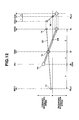
- Fig. 12 is a lever diagram of the hybrid transmission shown in Fig. 11 in the low mode.
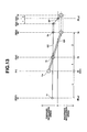
- Fig. 13 is a lever diagram of the hybrid transmission shown in Fig. 11 during the mode switch from the low mode to the second (2nd) mode.
- Fig. 14 is a lever diagram of the hybrid transmission shown in Fig. 11 in the second (2nd) mode.
- Fig. 15 is a lever diagram of the hybrid transmission shown in Fig. 11 in the high mode.
- Fig. 1 shows a hybrid transmission 1 to which a mode switch control apparatus in a preferred embodiment according to the present invention is applicable.
- hybrid transmission 1 is used as a transmission of a rear (road) wheel drive vehicle (so-called, FR vehicle).
- a reference numeral 11 denotes a transmission casing.
- Three simple planetary gear groups are coaxially arranged on the same axle toward right side (rear end far away from an engine ENG) of an axial direction of transmission casing 11.
- the three simple planetary gear groups are constituted by a front side planetary gear group GF nearest to engine ENG, a center planetary gear group GC, and a rear side planetary gear group GR which are coaxially incorporated into transmission casing 11.
- a motor/generator group which can be constituted by, for example, a compound (composite electrical) current two-layer motor 2 is coaxially arranged with the planetary gear groups described above at a position near to engine ENG. It is noted that front side planetary gear group GF, center planetary gear group GC, and rear side planetary gear group GR are correlated as follows to constitute a differential unit 3 having three degrees of freedom.
- front side planetary gear group GF, center planetary gear group GC, and rear side planetary gear group FR are simple planetary gear groups, each having three elements of a sun gear Sf, Sc, Sr, a ring gear Rf, Rc, Rr, and a carrier Cf, Cc, Cr.
- Ring gear Rr is coupled to carrier Cc, this coupling being coupled to an input axle 4 (denoted by Input In shown in lever diagrams of Figs. 2 through 5) through which a revolution of engine ENG is inputted via an engine clutch Cin.
- Carrier Cr is coupled to an output axle 5 (denoted by an Output Out shown in the lever diagrams of Figs. 2 through 5).
- Compound current two-layer motor 2 is coaxially and rotatably supported within transmission casing and is constituted by an inner rotor 2ri, annular outer rotor 2ro enclosing inner rotor 2ri, and an annular stator 2s located at an annular space between inner rotor 2ri and outer rotor 2ro and fixed to transmission casing 11.
- Annular stator 2a and outer rotor 2ro constitute a first motor/generator MG1 which is an outer motor/generator and annular stator 2s and inner rotor 2ri constitutes a second motor/generator MG2 which is an inner motor/generator.
- each of first and second motor/generators MG1, MG2 functions as a motor which outputs a revolution of individual direction and speed (including stop) in accordance with a supplied current when the compound current is supplied to motor side as a load and functions as a generator which develops an electrical power in accordance with a revolution thereof due to an external force when the compound current is supplied as the load of a generator side.
- First motor/generator MG1 (outer rotor 2ro) is coupled to ring gear Rc.
- Second motor/generator MG2 (inner rotor 2ri) is coupled to sun gear Sf, this sun gear Sf being coupled to sun gear Sc.
- a high clutch Chi is connectable between carrier Cf and sun gear Sf. This carrier Cf is fixable by means of a low brake B LO and ring gear Rf is coupled to sun gear Sr.
- a band brake type low-and-high brake B LH is wound on an outer periphery of outer rotor 2ro so that ring gear Rc coupled to outer rotor 2ro is fixable.
- a revolution degree of freedom of differential unit 3 is, as described above, three. In details, as will be described later, since one or more of low brake B LO , high clutch Chi, and low-and-high brake B LH are always operated to be engaged, the revolution degree of freedom of differential unit 3 is two or less. Hence, differential unit 3 is such that, if any two revolution speeds of the planetional elements of differential unit 3 are determined, the revolution speeds of all revolutional elements are determined.
- Ring gear Rc of planetary gear group GC is coupled to first motor/generator MG1.
- Input In from engine ENG is coupled to the coupling body of carrier Cc of planetary gear group GC and ring gear Rr of planetary gear group GR.
- Output axle 5 (Output Out toward a road wheel drive system) is coupled to carrier Cr of planetary gear group GR.
- Second motor/generator MG2 is coupled to sun gear Sc (or sun gear Sf of planetary gear group GF) in planetary gear group GC.
- ring gear Rc of planetary gear group GC is fixable by means of low-and-high brake B LH . It is noted that a lateral axis of each of Figs.
- 2 through 5 denotes a distance ratio between the revolutional elements determined according to a gear ratio of planetary gear groups GF, GR. That is to say, a ratio of the distance between carrier Cc (ring gear Rr) and ring gear Rc is ⁇ and a ratio of the distance between carrier Cr and sun gear Sr (sun gear Sc) is ⁇ when a distance between ring gear Rr and carrier Cr is 1.
- the distance ratio between the revolutional elements determined by the gear ratio of planetary gear group GC namely, a ratio of the distance between carrier Cf and ring gear Rf is ⁇ when the distance between sun gear Sf and carrier Cf is 1.
- a travel mode switch control in each embodiment is carried out by means of an integrated controller CON shown in Fig. 1.
- integrated controller CON a traveling mode map in which various travel modes as shown in Fig. 6 are assigned into a three dimensional space by a demanded driving force Fdrv (determined according to an accelerator opening angle), a vehicle speed VSP, and S.O.C. (State Of Charge) of a vehicular battery.
- Fdrv a demanded driving force
- VSP vehicle speed
- S.O.C. State Of Charge
- Fig. 6 is an example of the travel mode map represented in a two dimension of demanded driving force Fdrv and vehicle speed VSP by cutting the three-dimensional traveling mode map with a certain value in a capacity area in which the battery S.O.C. is sufficient.
- Low denotes the low mode in a fixed gear ratio
- Low-iVT denotes the low mode which is suitable for a continuously variable transmission (an infinitely variable transmission).
- High denotes the high mode in the fixed gear ratio
- High-iVT denotes the high mode in the continuously variable transmission
- EV denotes an electric vehicle mode
- HEV denotes a hybrid electric vehicle mode.
- Fig. 6 is an example of the travel mode map represented in a two dimension of demanded driving force Fdrv and vehicle speed VSP by cutting the three-dimensional traveling mode map with a certain value in a capacity area in which the battery S.O.C. is sufficient.
- Low denotes the low mode in a fixed gear ratio
- Low-iVT denotes the
- ACT denotes a hydraulic control actuator which supplies or drains a hydraulic to a low brake B LO , low-and-high clutch B LH , high clutch Chi, and engine clutch Cin so as to engage (fix) or release in accordance with a command (release or engage (fix)) from integrated controller CON.
- a revolution speed of carrier Cf is zero as shown in Fig. 2.
- the revolution of sun gear Sr with respect to sun gears Sc, Sf is reversed determined by a teeth number ratio between ring gear Rf and sun gear Sf.
- a revolution speed ⁇ o of output Out coupled to carrier Cr is lower than a revolution speed ⁇ in (engine speed inputted via engine clutch Cin) of input In connected to carrier Cc (ring gear Rr).
- this low mode is used in a region of a low side shift (gear) ratio including a backward gear (shift) ratio than the gear ratio (shift ratio) at which the revolution speeds of sun gear Sc and sin gear Sf are zeroed.
- revolution speed ⁇ in of input In is constant, second motor/generator MG2 causes a positive revolution of sun gear Sc to become high so that a reverse revolution of ring gear Rf is raised.
- the reverse revolution of sun gear Sr coupled to ring gear Rf is raised so that revolution speed ⁇ o of output Out is reduced.
- the gear (shift) ratio can be transferred to the low side. Furthermore, the transfer is carried out from the low side infinite (vehicular stop) state to backward gear (shift) ratio can be made.
- low side gear (shift) ratio can be fixed.
- a low-speed large torque traveling is possible by means of a large driving force which is the addition of the output of engine ENG and the output of second motor/generator MG2.
- second motor/generator MG2 functions as a generator, the traveling according to the output reduced by the engine output is possible.
- the high side gear (shift) ratio in the high mode can be fixed.
- a high speed travel by only engine ENG is possible.
- An assistance of the driving force by means of second motor/generator MG2 and an energy regeneration can be carried out during a deceleration.
- the driving performance and improvement of fuel consumption can be compatible during the high speed travel.
- the revolution speed ratio between input revolution speed ⁇ in and output revolution speed ⁇ o is fixed.
- the power of second motor/generator MG2 is adjustably outputted with the engine power. In this case, the fixed gear (shift) ratio is resulted even in the high mode.
- a mode switch from the low mode which is in (suitable for) the continuously variable transmission, the operation of low brake B LO causing carrier Cf being fixed, to the high mode which is (suitable for) in the continuously variable transmission, the operation of high clutch Chi coupling between sun gear Sf and carrier Cf, the mode switch being an object to be controlled according to the present invention, is as follows: In the low mode, first, high clutch Chi is engaged so that the lever diagram is transferred from the state of Fig. 2 to the state of Fig. 4 via state of Fig. 3. From the state of Fig. 4, low brake B LO is released so that the lever diagram is changed as shown in Fig. 5. At the same time, the torque control of second motor/generator MG2 to be carried out in association with the engagement advance of high clutch Chi and the release of low brake B LO and, then, the mode switch is carried out.
- the torque change of second motor/generator MG2 along with the polarity reversal develops the output torque variation and discontinuity of the change in the gear (shift) ratio so as to prevent a smooth mode switch from the low mode to the high mode and a reduction in quality of mode switching of the hybrid transmission is brought out.
- the mode switch from the continuously variable transmissible low mode to the same continuously variable transmissible high mode is carried out along with timing charts shown in Figs. 7A and 7B.
- Engine torque Te and torque Tmg1 of first motor/generator MG1 are controlled to be values to achieve a target driving force To and, during this control, the mode switch is carried out as described below.
- the gear (shift) ratio when, with both of low brake B LO and high clutch Chi engaged, the lever diagram is shown in Fig. 4 is defined as a mode switch gear ratio i0.
- a mode switch preparation is started at an instantaneous time t1 at which an actual gear ratio (may be a target gear ratio) i becomes the low side gear ratio by a predetermined ⁇ i1 with respect to mode switch gear ratio i0.
- This preparation is as follows: in order to render high clutch Chi to be switched from the release state to the engagement state toward an engagement start immediate before a state in which a loss stroke is finished, the control to supply a pre-charge pressure to this clutch Chi is started at instantaneous time t1.
- a torque capacity Tcc by which the pre-charged high clutch Chi is transmissible is raised from the instantaneous time t2 and this transmissible torque capacity Tcc is raised as the shift (gear) ratio i becomes closer to mode switch gear (shift) ratio i0.
- a value Tch of transmission torque capacity Tcc of high clutch Chi when gear ratio i becomes equal to the mode switch gear (shift) ratio i0 is a capacity derived by multiplying a high clutch torque Tc required after the mode is switched to the high mode under the present engine torque Te and torque Tmg1 of first motor/generator MG1 with a safety factor (for example, 1.2).
- Transmission torque capacity Tcc is commanded as a straight line varied from a command value 0 at the instantaneous time t2 to high clutch transmission torque capacity Tch required when (t4) the gear ratio i becomes mode switch gear ratio i0.
- torque Tmg2 of second motor/generator MG2 is started to be raised.
- the meaning of the raise in torque Tmg2 of second motor/generator MG2 is that, since torque Tmg2 of second motor/generator MG2 is negative value, the negative torque is, at first, reduced and the torque value is reversed at an instantaneous time t3', and the positive torque is raised (in a case where the transmission output torque is negative, the reverse occurs).
- torque Tmg2 of second motor/generator MG2 is a value such that the gear (shift) ratio i is changed to the mode switch gear (shift) ratio i0 from the low side gear ratio lower by ⁇ i3 than mode switch gear ratio i0 in accordance with the value of high clutch transmission capacity Tcc.
- torque Tmg2 value of second motor/generator MG2 is a torque value shown in Fig. 7A such that the gear (shift) ratio is advanced toward the high side for the torque value by which the gear (shift) ratio is balanced as represented by equation (1) (shown by a in Fig. 7A).
- torque value Tmg2 is a value which is smaller by a predetermined value (for example, 0.1 the torque after the gear shift) than the torque at which the gear (shift) ratio is balanced or the balance torque when high clutch torque Tc is multiplied with a predetermined value which is smaller by 1 than high clutch torque (for example, 1/1.2 provided that 1.2 is a safety factor of Tcc).
- equation (1) is the balance equation in a case where high clutch Chi is arranged so as to couple between sun gear Sf and carrier Cf.
- T m g 2 T c ⁇ ( 1 + ⁇ ) + T m g 1 ⁇ ⁇ / ( 1 + ⁇ ) + T o ⁇ ⁇ / ( 1 + ⁇ )
- the following mode switch end operation is carried out when it becomes an instantaneous time t4 of Figs. 7A and 7B at which gear (shift) ratio i has reached to mode switch gear (shift) ratio.
- the high clutch transmission torque capacity Tcc is raised at a speed in proportion to an elapse time from instantaneous time t4, for example, at the speed which is twice the torque capacity for one second when the gear ratio i has reached to the mode switch gear (shift) ratio i0.
- Torque Tmg2 of second motor/generator MG2 is raised in proportion to the elapse time from instantaneous time t4 and is changed to the direction (positive direction) at which the gear shift toward the high side at a variation rate at which, for example, 0.5 x absolute value of the torque required at the high mode + predetermined value (0.1 torque Tmg2 during the development of a high mode maximum driving force generation at high mode) has achieved within one second.
- Torque capacity Tbc at which low brake B LO is transmissible during the mode switch is determined according to the above equations in accordance with output torque To (driving force), engine torque Te, and torques Tmg1 and Tmg2 of first and second motor/generators MG1, MG2.
- Torque capacity Tbc is exemplified in Fig. 7A which is an addition of a value shown by b in Fig. 7A multiplied by a predetermined rate (for example, 1.2) to a predetermined value (for example, 0.05 low brake torque Tb at the time of a low mode maximum driving force at mode switch gear (shift) ratio i0).
- low brake transmission torque capacity Tb is negligible if it is more than necessary. However, since it is desirable to reduce a low brake transmission torque Tb to substantially zero when the gear (shift) ratio is shifted toward the higher side than mode switch gear (shift) ratio i0, low brake transmission capacity Tb is changed interlocking with high clutch torque Tc and torque Tmg2 of second motor/generator MG2. to provide substantially this required capacity.
- a one-way clutch OWC is disposed in parallel to low brake B LO as shown in Fig. 10.
- This one-way clutch OWC can serve as a low mode selection function in place of low brake B LO .
- Tbc transmission torque capacity
- a total torque of low brake torque Tb and one-way clutch torque can assuredly and sufficiently develop the required torque.
- a simple control permits the generation of the above action.
- both of the rise in transmission torque capacity Tcc of high clutch Chi for high mode selection and the change in torque Tmg2 along with the polarity reversal of second motor/generator MG2 during the mode switch from the continuously variable transmissible low mode to the continuously variable transmissible high mode are mutually interlocked and controlled.
- the smooth mode switch from the low mode to the high mode can be compensated.
- the mode switch quality is increased and the above-described problem to be solved by the present invention can be eliminated.
- transmissible torque capacity Tcc of pre-charged high clutch Chi is raised at instantaneous time t2 and this transmission torque capacity Tcc is raised as gear ratio i comes closer to mode switch gear (shift) ratio i0.
- a value Tch of transmission torque capacity Tcc of high clutch Chi when gear ratio i becomes mode switch gear ratio i0 is high clutch torque Tc required after the mode is switched to the high mode under the present engine torque Te and torque Tmg1 of first motor/generator MG1.
- Transmission torque capacity Tcc is commanded in accordance with the change in gear (shift) ratio i and as a value which is linearly changed to high clutch transmission torque capacity Tch required at instantaneous time (t4) at which the gear ratio i becomes mode switch gear (shift) ratio i0 from command value of 0 at instantaneous time t2.
- torque Tmg2 of second motor/generator MG2 is feedback controlled in such a way that actual gear ratio i is made coincident with target gear ratio i* and commanded as shown in Figs. 8A and 8B.
- the feedback control of torque Tmg2 of motor/generator takes the following methods.
- a correction value of torque Tmg2 of second motor/generator MG2 required to make actual gear (shift) ratio i coincident with target gear (shift) ratio i* is derived according to a PID control (Proportional control, Integration control, and Differential control) in accordance with an error between actual gear (shift) ratio i and target gear (shift) ratio i*, and this correction value is added to a theoretical value of torque Tmg2 of second motor/generator MG2 which can be determined from equation (1) so as to provide and output the command value of torque Tmg2 of second motor/generator MG2.
- PID control Proportional control, Integration control, and Differential control
- the following mode switch end operation is carried out at instantaneous time t4 at which actual gear ratio i has reached to mode switch gear ratio i0.
- One operation is the operation to completely engage high clutch Chi.
- High clutch transmission torque capacity Tcc is raised at the speed which is in proportion to an elapse time from instantaneous time t4, for example, twice the torque capacity when actual gear ratio i has reached to mode switch gear (shift) ratio i0 within one second.
- torque Tmg2 of second motor/generator MG2 is feedback controlled (PID) so that actual gear shift ratio i is made coincident with target gear (shift) ratio i*.
- Transmissible torque capacity Tbc of low brake B LO during the mode switch is a value determined according to the above equations in accordance with output torque To (driving force), engine torque Te, torques Tmg1 and Tmg2 of first and second motor/generators MG1 and MG2 multiplied with a predetermined rate (for example, 1.2) and added by the predetermined value (for example, 0.05 low brake torque Tb during the low mode maximum driving force generation at mode switch gear (shift) ratio i0) as shown in Fig. 8A.
- a predetermined rate for example, 1.2
- predetermined value for example, 0.05 low brake torque Tb during the low mode maximum driving force generation at mode switch gear (shift) ratio i0
- transmission torque capacity Tbc of low brake B LO is feedback controlled so that a slip quantity of low brake B LO is equal to or smaller than a predetermined value (for example, 50 rpm).
- a predetermined value for example, 50 rpm.
- a difference value of a subtraction of the predetermined value (50 rpm) from the slip quantity of low brake B LO (absolute value) is negative.
- the error is assumed to be zero. If the difference value is positive, this difference value is directly the error and a value derived by adding the correction quantity according to the PID control in accordance with this error to the above open control value is a command value of low brake transmission torque capacity Tbc.
- the above-described embodiment can be applied to the hybrid transmission in which one-way clutch is disposed in parallel to low brake B LO as shown in Fig. 10. However, in this case, it is not necessary to reduce transmission torque capacity Tbc of low brake B LO under a strict control. Even if transmission torque capacity Tbc is zeroed as shown by c in Fig. 8A before actual gear ratio i has reached to mode switch gear ratio i0 after high clutch is engaged, a total torque of low brake torque Tb and the one-way clutch torque can assuredly and sufficiently generate the required torque. The simple control can generate the above action.
- the mode switch control in this embodiment since the mutual interlocking control between the rise of transmission torque capacity Tcc of high clutch Chi for high mode selection and the change in torque Tmg2 along with the polarity reversal of second motor/generator MG2 is carried out, an output torque variation due to the change in torque Tmg2 of second motor/generator MG2 along with the polarity reversal and the discontinuity of the variation in the gear (shift) ratio variation are eliminated. At the same time, the smooth mode switch from the low mode to the high mode can be compensated. The mode switch quality is increased and the above-described problem can be eliminated.
- the mode switch control in this embodiement, when the interlock control between the rise in high clutch transmission capacity Tcc and the change in torque Tmg2 of motor/generator MG2 is carried out, the rise control of high clutch transmission torque capacity Tcc is in the open control and the control of torque Tmg2 of second motor/generator MG2 is the feedback control for making actual gear ratio i follow target gear ratio i*.
- the mode switch can be carried out.
- torque Tmg2 of second motor/generator MG2 is raised after instantaneous time t2 in Fig. 9A from the torque value in the low mode to the torque value required after the mode is switched to the high mode as the gear ratio i becomes closer to mode switch gear ratio i0.
- Torque Tmg2 of second motor/generator MG2 after instantaneous time t2 is set to be varied linearly in accordance with actual gear (shift) ratio i from required torque at the low mode at instantaneous time t2 to the required torque after the mode switch to the high mode.
- high clutch torque capacity Tcc is feedback controlled in such a way that actual gear ratio i is made coincident with the target gear (shift) ratio and is commanded as shown in Fig. 9A.
- the feedback control of high clutch transmission torque capacity Tcc takes the following way. On method is such that the actual gear (shift) ratio i (- ⁇ in/ ⁇ o) is calculated from transmission input revolution speed ⁇ in (refer to Figs. 2 through 5) and transmission output revolution speed ⁇ o (refer to Figs.
- torque Tmg2 of second motor/generator is a torque varied in proportion to the elapsed time from instantaneous time t4, for example, the torque varied in the direction (positive direction at which the higher side gear ratio occurs at a speed such that a sum of a value of 0.5 absolute value of the torque required in the high mode with a predetermined value (a torque value 0.1 torque Tmg2 when the maximum driving force which is predicted at the high mode under the mode switch gear ratio) is achieved within one second.
- Transmissible torque capacity Tbc of low brake B LO during the mode switch is a value determined according to the above equation in accordance with output torque To (driving force), engine torque Te, torques Tmg1, Tmg2 of first and second motor/generators MG1, MG2 multiplied with the predetermined rate (for example, 1.2) which is added to the predetermined value (for example, 0.05 low brake torque Tb at the time of low mode maximum driving force development at the mode switch gear ratio i0) (refer to Fig. 9A).
- the predetermined rate for example, 1.2
- transmission torque capacity Tbc of low brake torque B LO is feedback controlled so that the slip quantity of low brake B LO is equal to or smaller than the predetermined value (for example, 50 rpm).
- the predetermined value for example, 50 rpm.
- the difference value of subtraction of the predetermined value (50 rpm) from the slip quantity (absolute value) of low brake B LO is negative, the error is zeroed. If the difference values is positive, the value thereof is directly the error.
- a value derived by adding the correction quantity by means of PID control in accordance with the error to the open control value is a command value of low brake transmission torque capacity Tbc.
- the mode switch control in the other example described above the mutual interlocking control between the rise of transmission torque capacity Tcc of high clutch Chi for high mode selection and the change in torque Tmg2 along with the polarity reversal of motor/generator MG2 is carried out.
- the output torque variation and the discontinuity of the change in the gear (shift) ratio due to the torque (Tmg2) change of second motor/generator MG2 along with the polarity reversal are eliminated.
- the smooth mode switch from the low mode to the high mode can be compensated.
- the mode switch quality is increased the above-described problem to be solved can be eliminated.
- the mode switch control in this embodiment when the interlocking control between the rise in high clutch transmission torque capacity Tcc and the change in the motor/generator torque Tmg2 is carried out, the control for torque Tmg2 of second motor/generator MG2 is in the open control and the rise control of high clutch transmission torque capacity Tcc is in the feedback control for making actual gear (shift) ratio follow target gear (shift) ratio i*.
- the mode switch can be carried out so that the above action and advantage of eliminating the discontinuity of the gear ratio change can be more remarkable.
- transmissible torque capacity Tbc of low brake B LO engaged during the low mode selection is reduced in substantial synchronization with the mutual interlocking control between the rise of high clutch transmission capacity Tcc and the change in torque Tmg2 of second motor/generator MG2.
- one-way clutch (OWC) is not used in the hybrid transmission, as shown in Fig. 10
- the reduction in low brake transmission torque capacity Tbc for the above-described interlocking control is always appropriately carried out.
- an interlock tendency of the hybrid transmission during the mode switch can assuredly be avoided.
- the mode switch control apparatus has been explained in the case where the mode switch control apparatus is shown in Fig. 1 or Fig. 10.
- the hybrid transmission is not limited to these.
- the mode switch control apparatus according to the present invention is applicable to the hybrid transmission as shown in Fig. 11.
- hybrid transmission 1 shown in Fig. 11 is usable for the transmission for FR (Front engine rear wheel) car (rear wheel driven vehicle).
- FR Front engine rear wheel
- Fig. 11 the same parts as shown in Figs. 1 and 10 are designated by the same reference numerals and the overlapped explanations are avoided.
- compound current two-layer motor 2 constituting first and second motor/generators MG1, MG2, front side planetary gear group GF, center planetary gear group GC, and rear side planetary gear group GR in the order from a side of engine ENG, these components being coaxially arranged in the axial direction.
- front side planetary gear couple GF, center planetary gear couple GC, and rear side planetary gear group are correlated so as to have three degrees of freedom as will be described below.
- Input axle 4 (denoted by Input In in the lever diagrams of Figs. 12 through 15) through which the revolution of engine ENG is inputted via engine clutch Cin is coupled to ring gear Rr of planetary gear group GR.
- Carrier Cr of planetary gear group GR is coupled to output axle 5 (denoted by Out in the lever diagram of Figs. 11 through 14).
- First motor/generator MG1 (outer rotor 2ro) is coupled to sun gear Sc of planetary gear group GC.
- Second motor/generator MG2 (inner rotor 2ri) is coupled to ring gear Rf of planetary gear GF, this ring gear Rf being coupled to ring gear Rc of planetary gear group GC.
- High clutch Chi is connectable between ring gears Rf, Rc and carrier Cf of planetary gear group GF.
- This carrier Cf is fixable to low brake B LO and one-way clutch OWC is fixable in the same direction as described above.
- Sun gear Sf is coupled to sun gear Sr.
- Carriers Cc, Gr of planetary gear groups GC, GR are mutually coupled together.
- multiplate low-and-high brake B LH is installed to enable sun gear Sc coupled to outer rotor 2ro to be fixed is installed.
- Figs. 12 through 15 Lever diagrams of hybrid transmission 1 constructed in Fig. 11 are shown in Figs. 12 through 15.
- Input In is coupled to ring gear Rr of planetary gear group GR via engine clutch Cin.
- Output Out is coupled to mutual coupling body of carriers Cc, Cr of planetary gear groups GC, GR.
- Sun gear Sr of planetary gear group GR and ring gear Rc of planetary gear group GC are coupled to sun gear Sf and ring gear Rf of the planetary gear group GF, respectively.
- low brake B LO is disposed to fix carrier Cf of planetary gear group GF and high clutch Chi is disposed to couple mutually carrier Cf of planetary gear group GF and ring gear Rf thereof.
- First motor/generator MG1 (outer rotor 2ro) is coupled to sun gear Sc of planetary gear group GC and second motor/generator MG2 (inner rotor 2ri) is coupled to ring gear Rc (ring gear Rf of planetary gear group GF).
- Sun gear Sc of planetary gear group GC is fixable by means of low-and-high brake B LH .
- lateral axis shown in each of Figs. 12 through 15 denotes the distance ratio between revolutional elements determined according to the gear ratio of planetary gear group GC, GR.
- the distance ratio between ring gear Rr and sun gear Sc is represented by ⁇ and the distance ratio between carrier Cr (carrier Cc) and sun gear Sr (ring gear Rc) is represented by ⁇ when distance between ring gear Rr and carrier Cr (carrier Cc) is 1.
- the distance ratio between the revolutional elements determined according to the gear ratio in the planetary gear group GF namely, the distance ratio between carrier Cf and sun gear Sf of the same planetary gear group GF is represented by ⁇ .
- the low mode is used in a region of lower side gear (shift) ratio including the backward gear (shift) ratio than the gear (shift) ratio at which the revolution speeds of ring gears Rc, Rf are zero. Therefore, the low mode is used in a region of lower side gear (shift) ratio including the backward gear ratio than the gear ratio at which the revolution speeds of ring gears Rc, Rf are zeroed.
- gear (shift) ratio can be transferred to the low side.
- gear (shift) ratio can be transferred from the gear (shift) ratio of low side infinite (stop) to backward gear (shift) ratio.
- the low side gear ratio can be fixed.
- a large driving force which is the addition of engine output ENG and output of second motor/generator MG2 permits the travel in the low-speed, large torque. It is noted that, in this case, if second motor/generator MG2 is acted as the generator, the travel according to the output in which engine output is reduced by second motor/generator MG2 becomes possible.
- the power of second motor/generator MG2 can adjustably be outputted with engine power.
- the gear (shift) ratio becomes fixed gear (shift) ratio.
- the operation of high clutch Chi causes the coupling between ring gear Rf and carrier Cf.
- the engagement advance of high clutch Chi reduces the revolutions of ring gears Rc, Rf and sun gears Sf, Sr.
- the lever diagram is directed from the state shown in Fig. 12 to the state of Fig. 14 via the state of Fig. 13.
- the state enters in Fig. 14 in which revolution speeds of ring gears Rc, Rf and sun gears Sf, Sr are all zeroes.
- second (2nd) mode is selected.
- the power of first motor/generator MG1 can adjustably be outputted with the engine power.
- This second (2nd) mode is fixed gear (shift) ratio.
- the higher gear (shift) ratio in the high mode can be fixed.
- a high speed travel by means of only engine ENG becomes possible.
- Second motor/generator MG2 can assist the driving force and carry out the energy regeneration during the deceleration.
- the driving performance at the high speed travel and the improvement in the fuel consumption can be compatible.
- the revolution speed ratio between input revolution speed ⁇ in and output revolution ⁇ o is fixed.
- the power of second motor/generator MG2 is adjustably outputted with the engine power. In this case, even in the high mode, the gear (shift) ratio becomes fixed gear ratio.
- the mode switch which is the controlled object of the present invention from the continuously variable transmissible low mode in which the operation of low brake B LO causes carrier Cf to be fixed to the high mode in which the operation of high clutch Chi couples between ring gear Rf and carrier Cf is as follows: At first, high clutch Chi is coupled in the low mode so that the lever diagram is transferred from the state shown in Fig. 12 to the state shown in Fig. 14 via the state of Fig. 13. From the state shown in Fig. 14, low brake B LO is released so that the lever diagram becomes the state shown in Fig. 15. At the same time, the torque control of second motor/generator MG2 to be carried out in association with the engagement advance of high clutch Chi and the release of low brake B LO is carried out so that the mode switch is carried out.
- the torque change of second motor/generator MG2 along with the polarity reversal generates the output torque variation and discontinuity of the change in the gear (shift) ratio.
- the smooth mode switch from the low mode to the high mode is prevented so that the reduction of quality of the mode switch is brought out.
Landscapes
- Engineering & Computer Science (AREA)
- Transportation (AREA)
- Mechanical Engineering (AREA)
- Chemical & Material Sciences (AREA)
- Combustion & Propulsion (AREA)
- Automation & Control Theory (AREA)
- Electric Propulsion And Braking For Vehicles (AREA)
- Arrangement Of Transmissions (AREA)
- Control Of Transmission Device (AREA)
- Hybrid Electric Vehicles (AREA)
- Control Of Driving Devices And Active Controlling Of Vehicle (AREA)
- Structure Of Transmissions (AREA)
Claims (17)
- Modusschaltsteuervorrichtung für ein Hybridgetriebe (1), wobei das Hybridgetriebe enthält:eine Differentialeinheit (3), mittels derer ein Motor (ENG), eine Ausgangsachse(5, AUS) und zumindest ein Motor/ Generator (MG1, MG2) gegenseitig verbunden sind; eine Kupplung (Chi, Cin) mittels derer die ersten vorbestimmten Drehelemente der Differentialeinheit gegenseitig gekuppelt sind; und eine Bremse (BLO, BLH) mittels derer die zweiten Drehelemente der Differentialeinheit befestigt sind und das Hybridgetriebe wählbar ist zwischen einem niedrigen Modus (Low - ivT), der für ein veränderbares stufenloses Getriebe in einem Gangbereich auf der niedrigen Seite geeignet ist, und einem hohen Modus (High - ivT), der für das veränderbare stufenlose Getriebe in einem Gangbereich auf der hohen Seite geeignet ist, wobei ein Ausgangsdrehmoment des Motors / Generators durch eine Modusschaltsteuervorrichtung (CON) gemeinsam mit einer Polaritätsumkehrung in dem Motor / Generator von einem Drehmoment, gefordert in dem niedrigen Modus, zu einem Drehmoment, gefordert in dem hohen Modus, verändert wird, während ein Modusschalter von dem niedrigen Modus zu dem hohen Modus in einem Zustand, in dem ein Motorausgangsdrehmoment (Te) und eine Getriebeausgangs- Achsendrehmoment (To) im Wesentlichen unveränderlich sind, wobei die Modusschaltsteuervorrichtung (CON) eine gegenseitige Verriegelungssteuerung für beide eines Anstiegs in einer Drehmomentübertragungskapazität (TCC) entweder der Kupplung oder der Bremse ausführt, die von dem Freigabezustand zu einem Eingriffszustand, während der Modusumschaltung von dem niedrigen Modus zu dem hohen Modus geht, geschaltet wird, um den hohen Modus und die Drehmomentänderung (Tmg2) in dem Motor / Generator (MG2) gemeinsam mit der Polaritätsumkehr auszuwählen.
- Modusschaltsteuervorrichtung für ein Hybridgetriebe nach Anspruch 1, wobei die Modusschaltsteuervorrichtung (CON), um die gegenseitige Verriegelungssteuerung auszuführen, befiehlt, dass der Drehmomentübertragungskapazität (TCC) entweder der Kupplung oder der Bremse, die für die Auswahl des hohen Modus in einer offenen Steuerung und in einer Rückkopplungssteuerung für ein Ausgangsdrehmoment des Motors / Generators ist, um eine Drehzahl innerhalb des Hybridgetriebes dazu zu bringen, einem Zielwert zu folgen.
- Modusschaltsteuervorrichtung für ein Hybridgetriebe nach Anspruch 1, wobei die Modusschaltsteuervorrichtung, um eine gegenseitige Verriegelungssteuerung auszuführen, ein Ausgangsdrehmoment (Tmg2) des Motors / Generators (MG2) in eine offene Schleifensteuerung befiehlt und eine Rückkopplungssteuerung ausführt für die Drehmomentübertragungskapazität (Tcc) von entweder der Kupplung oder der Bremse, die für die Auswahl des hohen Modus ist, um die Drehzahl innerhalb des Hybridgetriebes dazu zu bringen, einem Zielwert zu folgen.
- Modusschaitsteuervorrichtung für ein Hybridgetriebe nach Anspruch 2, wobei die Drehzahl innerhalb des Hybridgetriebes ein tatsächliches Übersetzungsverhältnis (i) ist, das ein Verhältnis zwischen den Eingangs- und den Ausgangsdrehzahlen (ωin, ωo) des Hybridgetriebes (1) ist und die Modusschaltsteuervorrichtung (CON) die Rückkopplungssteuerung für das Ausgangsdrehmoment des Motors / Generators ausführt, um das tatsächliche Übersetzungsverhältnis (i) dazu zu bringen, dem Ziel- Übersetzungsverhältnis (i*) zu folgen.
- Modusschaltsteuervorrichtung für ein Hybridgetriebe nach Anspruch 3, wobei die Drehzahl innerhalb des Hybridgetriebes ein tatsächliche Übersetzungsverhältnis (i) ist, das ein Verhältnis zwischen den Eingangs- und den Ausgangsdrehzahlen (ωin, ωo) des Hybridgetriebes (1) ist und die Modusschaltsteuervorrichtung (CON) die Rückkopplungssteuerung für die Übertragungskapazität entweder von der Kupplung oder der Bremse ausführt, die für die Auswahl des hohen Modus ist, um das tatsächliche Übersetzungsverhältnis (i) dazu zu bringen, dem Ziel-Übersetzungsverhältnis (i*) zu folgen.
- Modusschaltsteuervorrichtung für ein Hybridgetriebe nach einem der vorhergehenden Ansprüche 1 bis 5, wobei die Übertragungsdrehmomentkapazität (Tbc) entweder von der Kupplung oder der Bremse, die während der Auswahl des niedrigen Modus im Eingriff ist, im Wesentlichen synchron mit der Verriegelungssteuerung reduziert wird.
- Modusschaltsteuervorrichtung für ein Hybridgetriebe nach einem der vorhergehenden Ansprüche 1 bis 6, wobei eine Freilaufkupplung (OWC), die funktioniert, um die Auswahl des niedrigen Modus auszuführen, an Stelle der Kupplung und der Bremse im Wesentlichen parallel zu entweder der Kupplung oder der Bremse, die für die Auswahl des niedrigen Modus ist, angeordnet ist, und eine (BLN) von entweder Kupplung oder Bremse, die für die Auswahl des niedrigen Modus in den Halbeingriffszustand durch die gegenseitige Verriegelungssteuerung gelöst ist.
- Hybridgetriebe (1), in dem ein Motor (ENG), eine Ausgangsachse (5, Aus) und zumindest ein Motor / Generator (MG1, MG2) mittels einer Differentialeinheit (3) verbunden sind, wobei erste vorbestimmte Drehelemente der Differentialeinheit gegenseitig miteinander mittels einer Kupplung gekuppelt sind oder zweite vorbestimmte Drehelemente mittels einer Bremse festgestellt sind, wobei das Hybridgetriebe aufweist: eine Steuerungseinrichtung (CON), um zwischen einem Eingriff und einem Freilauf der Kupplung oder der Bremse in Übereinstimmung mit dem Fahrzustand zu schalten, um einen vorbestimmten Fahrmodus auszuwählen, wobei die Steuerungseinrichtung die Ausgangsleistung des Motors und des Motors /Generators für ein Ausgangsachsendrehmoment (To) des Hybridgetriebes steuert, um dasselbe vor und nach einem Modusschalten zu sein und die Steuerungseinrichtung gegenseitig verriegelt, eine Drehmomentübertragungskapazität (Tcc) entweder (Chi) der Kupplung oder der Bremse, die im Eingriff ist, wenn die Modusschaltung ausgeführt wird und die Drehmomentänderung (Tmg2) des Motors / Generators (MG2) gemeinsam mit der Polaritätsumkehr in dem Motor / Generator ausgeführt wird, wenn die Polaritätsumkehrung in dem Motor / Generator involviert ist, bevor oder nachdem die Modusschaltung ausgeführt wird.
- Hybridgetriebe nach Anspruch 8, wobei der vorbestimmte Fahrmodus einen niedrigen Modus (Low- iVT), der für ein stufenlos veränderbares Getriebe in einem Übersetzungsverhältnis auf der niedrigen Seite geeignet ist, und einen hohen Modus (High- iVT), der für ein stufenlos veränderbares Getriebe in einem Übersetzungsverhältnis auf der hohen Seite geeignet ist, enthält, wobei die Steuerungseinrichtung wechselseitig einen Anstieg in der Drehmomentübertragungskapazität entweder von der Kupplung oder der Bremse, die von einem Freilaufzustand während der Modusschaltung im Eingriff ist, sperrt, um den hohen Modus auszuwählen und die Drehmomentänderung (Tmg2) des Motors / Generators (MG2) gemeinsam mit der Polaritätsumkehrung in dem Motor / Generator enthalten ist, bevor und nachdem die Modusschaltung in einem Zustand ausgeführt wird, in dem die Ausgangsdrehmomente (Te, To) des Motors und des Hybridgetriebes unveränderlich sind.
- Hybridgetriebe nach Anspruch 9, wobei die Steuerungseinrichtung (CON) die Drehmomentübertragungskapazität (Tcc) von entweder (Chi) der Kupplung oder der Bremse, die während der Modusschaltung von dem Freilaufzustand im Eingriff ist, befiehlt, um den hohen Modus in einer offenen Steuerung auszuwählen und eine Rückkopplungssteuerung für das Drehmoment (Tmg2) des Motors / Generators (MG2) auszuführen, in dem die Polaritätsumkehrung während der Modusschaltung enthalten ist, um eine Drehzahl innerhalb des Hybridgetriebes dazu zu bringen, dem Zielwert zu folgen.
- Hybridgetriebe nach Anspruch 9, wobei die Steuerungseinrichtung (CON) das Drehmoment (Tmg2) des Motors / Generators (MG2), in dem die Polaritätsumkehrung während der Modusschaltung in einer offenen Steuerung enthalten ist, und eine Rückkopplungssteuerung für die Drehmomentübertragungskapazität (Tcc) von entweder (Chi) der Kupplung oder der Bremse, die während der Modusschaltung von dem Freilaufzustand im Eingriff ist, befiehlt, um den hohen Modus auszuwählen, um eine Drehzahl innerhalb des Hybridgetriebes dazu zu bringen, dem Zielwert zu folgen.
- Hybridgetriebe nach Anspruch 10, wobei die Drehzahl innerhalb des Getriebes ein tatsächliches Übersetzungsverhältnis (i) ist, das ein Verhältnis zwischen den Eingangs- und den Ausgangsdrehzahlen (ωin, ωo) des Hybridgetriebes (1) ist, und wobei die Steuerungseinrichtung (CON) die Rückkopplungssteuerung für das Drehmoment (Tmg2) des Motors / Generators (MG2) ausführt, um das tatsächliche Übersetzungsverhältnis (i) dazu zu bringen, einem Ziel- Übersetzungsverhältnis (i*) zu folgen.
- Hybridgetriebe nach Anspruch 11, wobei die Drehzahl innerhalb des Getriebes ein tatsächliches Übersetzungsverhältnis (i) ist, das ein Verhältnis zwischen den Eingangs- und den Ausgangsdrehzahlen (ωin, ωo) des Hybridgetriebes (1) ist, und wobei die Steuerungseinrichtung (CON) die Rückkopplungssteuerung für die Drehmomentübertragungskapazität (Tcc) von entweder (Chi) der Kupplung oder der Bremse ausführt, die während der Modusschaltung von dem Freilaufzustand aus im Eingriff ist, um den hohen Modus auszuwählen, um das tatsächliche Übersetzungsverhältnis (i) dazu zu bringen, dem Ziel- Übersetzungsverhältnis (i*) zu folgen.
- Hybridgetriebe nach einem der der vorhergehenden Ansprüche 8 bis 13, wobei die Steuerungseinrichtung (CON) eine Drehmomentübertragungskapazität (Tbc) von entweder (BLO) der Kupplung oder der Bremse reduziert, die im Eingriff ist, bevor die Modusschaltung im Wesentlichen synchron mit dem gegenseitigen Verriegeln durch die Steuerungseinrichtung ausgeführt wird.
- Hybridgetriebe nach Anspruch 9, wobei das Hybridgetriebe eine Freilaufkupplung (OWC) enthält, die funktioniert, um eine Auswahl des niedrigen Modus an Stelle von entweder der Kupplung oder der Bremse auszuführen, die in dem niedrigen Modus vor der Modusschaltung im Eingriff ist und die parallel zu entweder der Kupplung oder der Bremse ist, die in dem niedrigen Modus im Eingriff ist, bevor die Modusschaltung ausgeführt wird, wobei die Steuerung eine (BLH) von Kupplung oder Bremse freigibt, die in dem niedrigen Modus im Eingriff ist, bevor die Modusschaltung halb ausgeführt ist, durch die Verriegelung durch die Steuerung.
- Hybridgetriebe nach einem der der vorhergehenden Ansprüche 8 bis 13, wobei die Steuerungseinrichtung (CON) gegenseitig einen Anstieg in der Drehmomentübertragungskapazität (Tcc) der Kupplung (Chi), die im hohen Modus während der Modusschaltung von dem niedrigen Modus zu dem hohen Modus im Eingriff ist, sperrt und die Veränderung in dem Drehmoment (Tmg2) des Motors / Generators (MG2), in dem die Polaritätsumkehrung während der Modusschaltung von dem niedrigen Modus zu dem hohen Modus enthalten ist.
- Steuerungsverfahren, anwendbar auf eine Hybridgetriebe (1), wobei ein Motor (ENG), eine Ausgangsachse (5, Aus) und zumindest ein Motor / Generator (MG1, MG2) mittels einer Differentialeinheit (3) gegenseitig verbunden sind, wobei erste vorbestimmte Drehelemente der Differentialeinheit gegenseitig miteinander mittels einer Kupplung (Chi, Cin) gekuppelt sind oder zweite vorbestimmte Drehelemente, die mittels einer Bremse (BLH, BLO) befestigt sind, wobei das Steuerungsverfahren aufweist: Schalten zwischen dem Eingriff und einem Freigeben der Kupplung oder der Bremse in Übereinstimmung mit einem Fahrzustand, um einen vorbestimmten Fahrmodus auszuwählen; Steuern der Ausgangsleistung des Motors und des Motors / Generators damit ein Ausgangsachsendrehmoment des Hybridgetriebes dasselbe ist, bevor oder nachdem eine Modusschaltung ausgeführt wird; und gegenseitiges Verriegeln einer Drehmomentübertragungskapazität (Tcc) von entweder (Chi) der Kupplung oder der Bremse, die im Eingriff ist, wenn die Modusschaltung ausgeführt wird und eine Drehmomentänderung (Tmg2) des Motors / Generators (MG2) gemeinsam mit einer Polaritätsumkehrung in dem Motor / Generator ausgeführt wird, wenn die Polaritätsumkehrung in dem Motor /Generator enthalten ist, bevor und nachdem die Modusschaltung ausgeführt wird.
Applications Claiming Priority (2)
| Application Number | Priority Date | Filing Date | Title |
|---|---|---|---|
| JP2003420458 | 2003-12-18 | ||
| JP2003420458A JP3858890B2 (ja) | 2003-12-18 | 2003-12-18 | ハイブリッド変速機のモード切り替え制御装置 |
Publications (2)
| Publication Number | Publication Date |
|---|---|
| EP1544019A1 EP1544019A1 (de) | 2005-06-22 |
| EP1544019B1 true EP1544019B1 (de) | 2006-08-23 |
Family
ID=34510659
Family Applications (1)
| Application Number | Title | Priority Date | Filing Date |
|---|---|---|---|
| EP04029240A Expired - Lifetime EP1544019B1 (de) | 2003-12-18 | 2004-12-09 | Vorrichtung und Verfahren zum Steuern der Umschaltung des Betriebsmodus |
Country Status (4)
| Country | Link |
|---|---|
| US (1) | US7404460B2 (de) |
| EP (1) | EP1544019B1 (de) |
| JP (1) | JP3858890B2 (de) |
| DE (1) | DE602004002073T2 (de) |
Families Citing this family (36)
| Publication number | Priority date | Publication date | Assignee | Title |
|---|---|---|---|---|
| DE10319880A1 (de) * | 2003-05-03 | 2004-11-18 | Daimlerchrysler Ag | Antriebsstrang mit einer Brennkraftmaschine und zwei elektrischen Antriebsaggregaten |
| JP3858898B2 (ja) * | 2004-02-13 | 2006-12-20 | 日産自動車株式会社 | ハイブリッド変速機のモード切り替え制御装置 |
| JP4215032B2 (ja) * | 2005-06-24 | 2009-01-28 | トヨタ自動車株式会社 | 車両用駆動装置の制御装置 |
| WO2007104161A1 (en) * | 2006-03-15 | 2007-09-20 | Tm4 Inc. | Hybrid transmission for hybrid vehicles |
| DE102006034933B4 (de) * | 2006-07-28 | 2016-10-06 | Dr. Ing. H.C. F. Porsche Aktiengesellschaft | Verfahren und Vorrichtung zur Steuerung eines Hybrid-Fahrzeugantriebs |
| US8121768B2 (en) * | 2007-11-05 | 2012-02-21 | GM Global Technology Operations LLC | Method for controlling a hybrid powertrain system based upon hydraulic pressure and clutch reactive torque capacity |
| DE102007055830A1 (de) * | 2007-12-17 | 2009-06-18 | Zf Friedrichshafen Ag | Verfahren und Vorrichtung zum Betrieb eines Hybridantriebes eines Fahrzeuges |
| US8091659B2 (en) * | 2007-12-27 | 2012-01-10 | Byd Co. Ltd. | Hybrid vehicle having engageable clutch assembly coupled between engine and traction motor |
| US8272464B2 (en) * | 2008-04-04 | 2012-09-25 | GM Global Technology Operations LLC | Motor assembly for alternative fuel vehicles |
| US20100156210A1 (en) * | 2008-12-19 | 2010-06-24 | Tai-Her Yang | Bidirectional unequal speed electric motor driven constant directional output system |
| CN101789755B (zh) * | 2008-12-19 | 2015-05-20 | 杨泰和 | 双向不等速电马达恒向输出驱动系统 |
| US8143823B2 (en) * | 2008-12-19 | 2012-03-27 | Tai-Her Yang | Bidirectional different speed ratio electric motor driving device with bidirectional input |
| US8143822B2 (en) * | 2008-12-19 | 2012-03-27 | Tai-Her Yang | Bidirectional unequal speed electric motor driven bidirectional output system |
| JP5260399B2 (ja) * | 2009-04-24 | 2013-08-14 | 日立オートモティブシステムズ株式会社 | 車両駆動用回転電機およびそれを用いた車両 |
| US20120013211A1 (en) * | 2010-07-16 | 2012-01-19 | Remy Technologies, L.L.C. | Electric motor having a selectively adjustable base speed |
| JP5598252B2 (ja) * | 2010-10-22 | 2014-10-01 | 日産自動車株式会社 | 電動車両の制御装置 |
| US8636620B2 (en) | 2010-10-28 | 2014-01-28 | Jatco Ltd | Automatic transmission |
| JP5496854B2 (ja) | 2010-11-01 | 2014-05-21 | ジヤトコ株式会社 | 車両の制御装置 |
| JP5383626B2 (ja) | 2010-11-01 | 2014-01-08 | ジヤトコ株式会社 | 車両の制御装置 |
| JP5693152B2 (ja) | 2010-11-01 | 2015-04-01 | ジヤトコ株式会社 | 車両の油圧制御装置 |
| JP5693151B2 (ja) | 2010-11-01 | 2015-04-01 | ジヤトコ株式会社 | 車両の制御装置 |
| JP5496855B2 (ja) | 2010-11-01 | 2014-05-21 | ジヤトコ株式会社 | 車両の制御装置 |
| JP5501937B2 (ja) * | 2010-11-02 | 2014-05-28 | ジヤトコ株式会社 | ハイブリッド車両の制御装置 |
| JP5429400B2 (ja) * | 2010-11-04 | 2014-02-26 | トヨタ自動車株式会社 | 車両用ハイブリッド駆動装置 |
| JP5501260B2 (ja) | 2011-02-03 | 2014-05-21 | ジヤトコ株式会社 | 車両の制御装置 |
| US9168911B2 (en) * | 2011-12-19 | 2015-10-27 | Toyota Jidosha Kabushiki Kaisha | Drive control device for hybrid vehicle |
| CN104203692B (zh) * | 2012-03-26 | 2017-03-08 | 丰田自动车株式会社 | 混合动力车辆的驱动控制装置 |
| US9580065B2 (en) | 2012-07-17 | 2017-02-28 | Altigreen Propulsion Labs Private Limited | Dual-structured electric drive and power system for hybrid vehicles |
| US9441599B2 (en) | 2012-07-17 | 2016-09-13 | Altigreen Propulsion Labs Private Limited | Induction motor-permanent magnet generator tandem configuration starter-generator for hybrid vehicles |
| US9421968B2 (en) * | 2013-12-18 | 2016-08-23 | Hyundai Motor Company | System and method for controlling torque for hybrid vehicle |
| DE102014208799A1 (de) * | 2014-05-09 | 2015-11-12 | Zf Friedrichshafen Ag | Getriebe mit einem Elektromotor |
| WO2017189418A1 (en) * | 2016-04-25 | 2017-11-02 | Thyssenkrupp Elevator Corporation | Energy-efficient elevator doors and methods of operating same |
| WO2017207061A1 (de) * | 2016-06-03 | 2017-12-07 | Gkn Automotive Ltd. | Elektroantriebsanordnung und antriebsstrang mit einer solchen elektroantriebsanordnung |
| US11505063B2 (en) | 2018-05-30 | 2022-11-22 | Carrier Corporation | Energy management systems (EMS) for transportation refrigeration units (TRU) |
| DE102019123367A1 (de) * | 2019-08-30 | 2021-03-04 | Knorr-Bremse Systeme für Nutzfahrzeuge GmbH | Antriebsstrang für ein Fahrzeug |
| CN113619562B (zh) * | 2021-08-23 | 2024-04-23 | 同济大学 | 一种混合动力汽车模式切换工况下瞬态冲击抑制方法 |
Family Cites Families (15)
| Publication number | Priority date | Publication date | Assignee | Title |
|---|---|---|---|---|
| IL49201A (en) * | 1976-03-12 | 1980-02-29 | Scientific Res Foundation | Vehicle drive system including a flywheel and selectable coupling means |
| US4393964A (en) * | 1979-03-23 | 1983-07-19 | Ipanema Company | Hybrid power system and method for operating same |
| US5172787A (en) * | 1989-04-28 | 1992-12-22 | Fuji Jukogyo Kabushiki Kaisha | Restricting device for a differential in a motor vehicle |
| US5342258A (en) * | 1991-08-16 | 1994-08-30 | Motion Sciences Inc. | Combinational incrementally variable transmissions and other gearing arrangements allowing maximum kinematic degrees of freedom |
| US5632354A (en) * | 1993-09-16 | 1997-05-27 | Fuji Jukogyo Kabushiki Kaisha | Motor vehicle with a continuously variable transmission |
| JP3350314B2 (ja) * | 1995-09-29 | 2002-11-25 | 富士重工業株式会社 | ハイブリッド自動車の駆動装置 |
| JPH11107798A (ja) | 1997-10-08 | 1999-04-20 | Aisin Aw Co Ltd | ハイブリッド駆動装置 |
| AUPP373798A0 (en) * | 1998-05-27 | 1998-06-18 | Williames, Geoffrey Allan | Vehicle powertrains |
| US5931757A (en) | 1998-06-24 | 1999-08-03 | General Motors Corporation | Two-mode, compound-split electro-mechanical vehicular transmission |
| JP2000224714A (ja) | 1999-02-03 | 2000-08-11 | Mitsubishi Motors Corp | 電動機付車両 |
| US6579201B2 (en) | 2000-08-22 | 2003-06-17 | New Venture Gear, Inc. | Electric hybrid four-wheel drive vehicle |
| US6527658B2 (en) | 2001-04-02 | 2003-03-04 | General Motors Corporation | Electrically variable transmission with selective input split, compound split, neutral and reverse modes |
| WO2003035421A1 (en) | 2001-10-22 | 2003-05-01 | The Timken Company | Electro-mechanical infinitely variable transmission |
| JP3535140B2 (ja) * | 2002-05-23 | 2004-06-07 | 本田技研工業株式会社 | ハイブリッド車両 |
| JP3823949B2 (ja) | 2003-06-23 | 2006-09-20 | 日産自動車株式会社 | ハイブリッド車のモード遷移制御装置 |
-
2003
- 2003-12-18 JP JP2003420458A patent/JP3858890B2/ja not_active Expired - Fee Related
-
2004
- 2004-12-07 US US11/004,875 patent/US7404460B2/en not_active Expired - Lifetime
- 2004-12-09 EP EP04029240A patent/EP1544019B1/de not_active Expired - Lifetime
- 2004-12-09 DE DE602004002073T patent/DE602004002073T2/de not_active Expired - Lifetime
Also Published As
| Publication number | Publication date |
|---|---|
| US7404460B2 (en) | 2008-07-29 |
| DE602004002073D1 (de) | 2006-10-05 |
| DE602004002073T2 (de) | 2007-01-11 |
| JP3858890B2 (ja) | 2006-12-20 |
| US20050133286A1 (en) | 2005-06-23 |
| EP1544019A1 (de) | 2005-06-22 |
| JP2005180533A (ja) | 2005-07-07 |
Similar Documents
| Publication | Publication Date | Title |
|---|---|---|
| US7404460B2 (en) | Mode switch control apparatus and method for hybrid transmission | |
| EP1491427B1 (de) | Steuerung und Verfahren zum Wechseln der Betriebsart für ein Hybridfahrzeug | |
| JP4401284B2 (ja) | ハイブリッド電気自動車用二重クラッチ変速機 | |
| EP1564056B1 (de) | Schaltmodussteuerung für ein Hybridgetriebe | |
| EP1529672B1 (de) | Antriebskraftsteuerung und Vorrichtung für ein Hybridfahrzeug | |
| EP0937600B1 (de) | Hybridantriebssystem und hiermit versehenes Fahrzeug | |
| EP1260397B1 (de) | Steuerungsverfahren für ein Hybridfahrzeug während eines Rückwärtsmanövers | |
| US8948945B2 (en) | Hybrid vehicle | |
| CN105142949B (zh) | 用于混合动力驱动系统的扭矩叠加装置、混合动力驱动系统及运行混合动力驱动系统的方法 | |
| KR101509935B1 (ko) | 하이브리드 차량의 동력전달장치 | |
| CN107128160B (zh) | 用于混合动力电动车辆的车桥总成 | |
| JP2013147237A (ja) | 車両用駆動装置 | |
| JP5104493B2 (ja) | 動力出力装置および車両 | |
| US10933862B2 (en) | Vehicle control system | |
| CN104220315B (zh) | 车辆用驱动装置 | |
| JP2007022483A (ja) | ハイブリッド変速機のモード遷移制御方法 | |
| EP4166820A1 (de) | Fahrzeugantriebsvorrichtung | |
| JP4013863B2 (ja) | ハイブリッド車両の駆動装置 | |
| JP2021187312A (ja) | 車両用駆動装置 | |
| US11970084B2 (en) | Vehicle drive device and control method for the same | |
| EP4223603B1 (de) | Antriebsvorrichtung für ein fahrzeug | |
| CN109823161A (zh) | 一种车用三电机混合动力变速驱动系统及其控制方法 | |
| JP2022156339A (ja) | 車両用駆動装置 | |
| JP2007050776A (ja) | ハイブリッド変速機 |
Legal Events
| Date | Code | Title | Description |
|---|---|---|---|
| PUAI | Public reference made under article 153(3) epc to a published international application that has entered the european phase |
Free format text: ORIGINAL CODE: 0009012 |
|
| 17P | Request for examination filed |
Effective date: 20041209 |
|
| AK | Designated contracting states |
Kind code of ref document: A1 Designated state(s): AT BE BG CH CY CZ DE DK EE ES FI FR GB GR HU IE IS IT LI LT LU MC NL PL PT RO SE SI SK TR |
|
| AX | Request for extension of the european patent |
Extension state: AL BA HR LV MK YU |
|
| GRAP | Despatch of communication of intention to grant a patent |
Free format text: ORIGINAL CODE: EPIDOSNIGR1 |
|
| AKX | Designation fees paid |
Designated state(s): DE FR GB |
|
| GRAS | Grant fee paid |
Free format text: ORIGINAL CODE: EPIDOSNIGR3 |
|
| GRAA | (expected) grant |
Free format text: ORIGINAL CODE: 0009210 |
|
| AK | Designated contracting states |
Kind code of ref document: B1 Designated state(s): DE FR GB |
|
| REG | Reference to a national code |
Ref country code: GB Ref legal event code: FG4D |
|
| REF | Corresponds to: |
Ref document number: 602004002073 Country of ref document: DE Date of ref document: 20061005 Kind code of ref document: P |
|
| ET | Fr: translation filed | ||
| PLBE | No opposition filed within time limit |
Free format text: ORIGINAL CODE: 0009261 |
|
| STAA | Information on the status of an ep patent application or granted ep patent |
Free format text: STATUS: NO OPPOSITION FILED WITHIN TIME LIMIT |
|
| 26N | No opposition filed |
Effective date: 20070524 |
|
| REG | Reference to a national code |
Ref country code: FR Ref legal event code: PLFP Year of fee payment: 12 |
|
| PGFP | Annual fee paid to national office [announced via postgrant information from national office to epo] |
Ref country code: GB Payment date: 20151209 Year of fee payment: 12 Ref country code: DE Payment date: 20151201 Year of fee payment: 12 |
|
| PGFP | Annual fee paid to national office [announced via postgrant information from national office to epo] |
Ref country code: FR Payment date: 20151110 Year of fee payment: 12 |
|
| REG | Reference to a national code |
Ref country code: DE Ref legal event code: R119 Ref document number: 602004002073 Country of ref document: DE |
|
| GBPC | Gb: european patent ceased through non-payment of renewal fee |
Effective date: 20161209 |
|
| REG | Reference to a national code |
Ref country code: FR Ref legal event code: ST Effective date: 20170831 |
|
| PG25 | Lapsed in a contracting state [announced via postgrant information from national office to epo] |
Ref country code: FR Free format text: LAPSE BECAUSE OF NON-PAYMENT OF DUE FEES Effective date: 20170102 |
|
| PG25 | Lapsed in a contracting state [announced via postgrant information from national office to epo] |
Ref country code: GB Free format text: LAPSE BECAUSE OF NON-PAYMENT OF DUE FEES Effective date: 20161209 Ref country code: DE Free format text: LAPSE BECAUSE OF NON-PAYMENT OF DUE FEES Effective date: 20170701 |