EP1541508A1 - Vorrichtung zum Abbauen eines Stapels von flächigen Gegenständen - Google Patents
Vorrichtung zum Abbauen eines Stapels von flächigen Gegenständen Download PDFInfo
- Publication number
- EP1541508A1 EP1541508A1 EP04021996A EP04021996A EP1541508A1 EP 1541508 A1 EP1541508 A1 EP 1541508A1 EP 04021996 A EP04021996 A EP 04021996A EP 04021996 A EP04021996 A EP 04021996A EP 1541508 A1 EP1541508 A1 EP 1541508A1
- Authority
- EP
- European Patent Office
- Prior art keywords
- stack
- suction
- support
- suction head
- sliding
- Prior art date
- Legal status (The legal status is an assumption and is not a legal conclusion. Google has not performed a legal analysis and makes no representation as to the accuracy of the status listed.)
- Granted
Links
Images


Classifications
-
- B—PERFORMING OPERATIONS; TRANSPORTING
- B65—CONVEYING; PACKING; STORING; HANDLING THIN OR FILAMENTARY MATERIAL
- B65H—HANDLING THIN OR FILAMENTARY MATERIAL, e.g. SHEETS, WEBS, CABLES
- B65H83/00—Combinations of piling and depiling operations, e.g. performed simultaneously, of interest apart from the single operation of piling or depiling as such
- B65H83/02—Combinations of piling and depiling operations, e.g. performed simultaneously, of interest apart from the single operation of piling or depiling as such performed on the same pile or stack
-
- B—PERFORMING OPERATIONS; TRANSPORTING
- B65—CONVEYING; PACKING; STORING; HANDLING THIN OR FILAMENTARY MATERIAL
- B65H—HANDLING THIN OR FILAMENTARY MATERIAL, e.g. SHEETS, WEBS, CABLES
- B65H29/00—Delivering or advancing articles from machines; Advancing articles to or into piles
- B65H29/66—Advancing articles in overlapping streams
- B65H29/6645—Advancing articles in overlapping streams buffering an overlapping stream of articles
-
- B—PERFORMING OPERATIONS; TRANSPORTING
- B65—CONVEYING; PACKING; STORING; HANDLING THIN OR FILAMENTARY MATERIAL
- B65H—HANDLING THIN OR FILAMENTARY MATERIAL, e.g. SHEETS, WEBS, CABLES
- B65H29/00—Delivering or advancing articles from machines; Advancing articles to or into piles
- B65H29/66—Advancing articles in overlapping streams
- B65H29/6654—Advancing articles in overlapping streams changing the overlapping figure
- B65H29/6663—Advancing articles in overlapping streams changing the overlapping figure reversing the overlapping figure
-
- B—PERFORMING OPERATIONS; TRANSPORTING
- B65—CONVEYING; PACKING; STORING; HANDLING THIN OR FILAMENTARY MATERIAL
- B65H—HANDLING THIN OR FILAMENTARY MATERIAL, e.g. SHEETS, WEBS, CABLES
- B65H3/00—Separating articles from piles
- B65H3/08—Separating articles from piles using pneumatic force
- B65H3/0808—Suction grippers
- B65H3/0816—Suction grippers separating from the top of pile
-
- B—PERFORMING OPERATIONS; TRANSPORTING
- B65—CONVEYING; PACKING; STORING; HANDLING THIN OR FILAMENTARY MATERIAL
- B65H—HANDLING THIN OR FILAMENTARY MATERIAL, e.g. SHEETS, WEBS, CABLES
- B65H3/00—Separating articles from piles
- B65H3/24—Separating articles from piles by pushers engaging the edges of the articles
-
- B—PERFORMING OPERATIONS; TRANSPORTING
- B65—CONVEYING; PACKING; STORING; HANDLING THIN OR FILAMENTARY MATERIAL
- B65H—HANDLING THIN OR FILAMENTARY MATERIAL, e.g. SHEETS, WEBS, CABLES
- B65H2301/00—Handling processes for sheets or webs
- B65H2301/40—Type of handling process
- B65H2301/42—Piling, depiling, handling piles
- B65H2301/421—Forming a pile
- B65H2301/4212—Forming a pile of articles substantially horizontal
- B65H2301/42122—Forming a pile of articles substantially horizontal by introducing articles from under the pile
-
- B—PERFORMING OPERATIONS; TRANSPORTING
- B65—CONVEYING; PACKING; STORING; HANDLING THIN OR FILAMENTARY MATERIAL
- B65H—HANDLING THIN OR FILAMENTARY MATERIAL, e.g. SHEETS, WEBS, CABLES
- B65H2301/00—Handling processes for sheets or webs
- B65H2301/40—Type of handling process
- B65H2301/42—Piling, depiling, handling piles
- B65H2301/421—Forming a pile
- B65H2301/4213—Forming a pile of a limited number of articles, e.g. buffering, forming bundles
-
- B—PERFORMING OPERATIONS; TRANSPORTING
- B65—CONVEYING; PACKING; STORING; HANDLING THIN OR FILAMENTARY MATERIAL
- B65H—HANDLING THIN OR FILAMENTARY MATERIAL, e.g. SHEETS, WEBS, CABLES
- B65H2404/00—Parts for transporting or guiding the handled material
- B65H2404/60—Other elements in face contact with handled material
- B65H2404/65—Other elements in face contact with handled material rotating around an axis parallel to face of material and perpendicular to transport direction, e.g. star wheel
- B65H2404/654—Other elements in face contact with handled material rotating around an axis parallel to face of material and perpendicular to transport direction, e.g. star wheel having more than 4 elements
-
- B—PERFORMING OPERATIONS; TRANSPORTING
- B65—CONVEYING; PACKING; STORING; HANDLING THIN OR FILAMENTARY MATERIAL
- B65H—HANDLING THIN OR FILAMENTARY MATERIAL, e.g. SHEETS, WEBS, CABLES
- B65H2404/00—Parts for transporting or guiding the handled material
- B65H2404/70—Other elements in edge contact with handled material, e.g. registering, orientating, guiding devices
- B65H2404/73—Means for sliding the handled material on a surface, e.g. pushers
- B65H2404/731—Means for sliding the handled material on a surface, e.g. pushers moved in a path enclosing an area
Definitions
- the present invention relates to a device for Dismantling a stack of flat objects, in particular printed matter, according to the preamble of claim 1
- a device of this kind is known from WO-A-00/46135 known.
- a belt conveyor forming a stack support leads a pile of constantly new down Printed matter to; the belt conveyor is in his Location unchangeable.
- Above the belt conveyor a lifting and Abschiebetician is arranged, the because of their support on the stack top and their movable storage is capable of changing To follow level of the top of the stack.
- the heights slidably mounted lifting and Abschiebetician is connected to a conveyor designed as a rocker, which is meant to be raised from the stack and him pushed flat objects, in particular Printed matter, in a scale formation in which every object on the subject matter.
- a sucker arrangement the lifting and Abschiebeaji has two longitudinally guided, Suction heads connected to a vacuum wave, the by means of a compression spring in an extended The takeover position are urged, in which they are the exposed flat side of the top object of the Lean against the stack and lift it until the Suction heads are in their retracted delivery position.
- a slide-away unit of the lifting and Abschiebeaji points to an endless conveyor chain in regular Clearances attached shift cams. The raised The subject is in each case at his in Wegschieberaum seen trailing edge of sliding cam attacked and pushed the conveyor. It will the object is pushed away from the suction cups, which under the action of the compression spring back into their front Takeover position to return to the next lift stack top object from this.
- the Lifting and Abschiebetician is by means of a Support assembly supported on the top of the stack, so that the suction cups in their fully extended Takeover position respectively the top item to raise it.
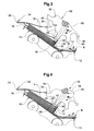
- the device shown in FIG. 1 has a Stacking pad 10, which by means of a as Ribbon conveyor trained feeder 12 in Feed direction Z flexible flat objects 14, in present case folded printed products, fed to the stack support 10 one of Bottom of stack 16 of articles 14 to form.
- the viewed in the feeding direction Z at an angle of about 35 ° rising arranged stack support 10 has flat support plate 18 and a ribbon conveyor 20, in the feed direction Z at the same speed as the feed conveyor 12 is driven.
- the active strand 22 of the Ribbon conveyor crosses - seen in view - the active one Run of the feed conveyor 12 and then runs on the Top of the support plate 18 to a guide roller 24, in the feed Z between the middle and 2/3 the length of the stack support 10 is located.
- This Guide pulley 24 extends the passive strand 22 'of the Ribbon conveyor 20 to another deflection roller 24 'in End region of the feed conveyor 12.
- End region of the stack support 10 is a support plate arranged, which is perpendicular to the stack support 10th runs and is spaced at a distance to this for the articles 16 to be supplied to the stack 16 Feed gap to form.
- the support plate 30 supports the stacked items 14 on the feed conveyor 12th facing away from.
- the support plate 30 is in his, the stack support 10th facing end of coaxially mounted Adphaseswalzen 32 penetrated, on the one hand the Inserting the articles 14 under the stack 16 support and serve on the other hand, on the stack 16 supplied items 14 at their in the feed direction Z seen trailing edge 34 of the stack support 10th lifting away and the clean concern of the Objects 14 with their trailing edge 34 am To promote stop plate 26.
- the overhead ones Objects 14 of the stack 16 are thus aligned with its trailing edge 34 on the support plate 30 at.
- a Sucker assembly 36 with a suction head 38 This is in one fixed to a machine frame, not shown arranged guide member 40 in an approximately rectangular slidable to the stack support 10 extending direction stored.
- the tubular suction head 38 has a Suction port 42, which during the dismantling of the stack 16 is permanently connected to a vacuum source 44.
- a suction head 38 of the sucker assembly 36 is shown in FIG. 10 shown; such a Saugeranorndung 36 is for example, also disclosed in WO-A-00/46135.
- the tubular guide member 40 in the tubular guide member 40 is the tubular Suction head 38 telescopically mounted and by means of a formed by a compression spring Return element 46 in the direction of an extended Pre-tensioned takeover position.
- the maximal Extend position is by a stop shoulder 50 on Guide member 40 given, which with a counter-shoulder 50 'cooperates on the suction head 38.
- On the suction head 38 facing away from the restoring element 46 on an am Guide member 40 fixed connection pipe 52nd supported, of which a hose 54 for Low pressure source 44 leads.
- the suction head 38 If the suction head 38 is connected to the vacuum source 44 and in takeover position 48, the suction opening 42 through the closed top object 14 of the stack 16, moves the suction head 38 against the detected object 14 against the effect of the return element 46 of the extended Takeover position 48 in a retracted delivery position 48 ', in which, for example, the suction opening 42 itself at the front end of the guide element 40th located. If the raised object 14 of the Suction opening 42 pushed away, the suction head 38 moves under the action of the return element 46 immediately after Release by the article 14 automatically back in his extended takeover position 48 to the next To lift the item 14 from the stack 16.
- a Wegschiebean Aunt 56 with a Wegschiebecardi W powered wheel 58 This sits on one driven shaft 58 ', which is horizontal and rectangular to the feed direction Z running on the machine frame is stored stationary.
- the sliding wheel 58 is star-like educated.
- the approximately projecting in the radial direction Sliding arms 60 are in their radially outer end regions formed as sliding members 62, wherein the leading Flank 64 is used to push the objects 14 and a over the edge 64 in the direction of displacement W against the front protruding nose 66 for grasping the respectively wegzuschiebenden object 14 is used.
- the radially outside lying end face of each sliding member 62 and Schiebearms 60 forms a stop 68, whose operation continues to describe below.
- the dash-dotted orbit 70 of the Sliding members 62 extends between the stack 16 and the Abgabeposition 48 of the suction head 38 at a distance.
- the axis of rotation the sliding wheel 58 and the longitudinal axis of the suction head 38 almost cross each other.
- the shaft 58 'and thus the axis of rotation of the sliding wheel 58th are about the same height as the Item stop 28, and the distance between the Orbit 70 of the sliding members 62 and the For example, item stop 28 is 10-20% shorter than the length L of the articles 14.
- a first guide wheel 72 is mounted and resilient in Direction biased against the sliding gear 58.
- an elastic pressure belt 74 which approximately centrally above the sliding wheel 58 to a second deflecting wheel 72 'runs around.
- the pressing belt 74 forms, together with the sliding wheel 58, a conveying gap 76 for the lifted from the stack 16 and of a subjugate in a supershot situation spent items 14.
- a Guide roller 78 designed as a ribbon conveyor Off-conveyor 80 stored in such a way that the horizontal top lying active Trum of the pulley 78th from inside a imaginary conveyor belt tangentially defined by the orbit 70 cylinder touched to those conveyed out of the conveying gap 76 Promote objects in the conveying direction F.
- the Conveying direction F is opposite to Feed direction Z.
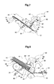
- FIG. 1 The embodiment shown in FIG. 1 is that according to FIG. 1 same, with the exception of the elements for the displacement of the from the stack 16 raised and pushed away objects 14.
- Parallel axis to the shaft 58 'of the sliding wheel 58 is mounted on the machine frame, a guide roller 82, the similar point as the first guide wheel 72 in the Training form according to FIG. 1 is arranged.
- both sides the sliding wheel 58 between the shaft 58 'and the Deflection roller 82 is each a first guide wheel 72 freely rotatable stored and in a direction approximately perpendicular to a from the axis of the sliding wheel 58 and the axis of the Deflection roller 82 certain level on the stack support 10th biased to spring back urgently.
- the first Guide pulley 72 To the first Guide pulley 72 is a pressure belt 74 out, whose lower active strand with the guide roller 82 a Conveying gap 76 forms to the lifted off the stack 16 and pushed away items 14, after being moved into the devisschl foundede position to the guide roller 82 around promote.
- the second deflection wheel 72 'for the pressure belt 74 is mounted above the deflection roller 78.
- the pulleys 78 of the removal conveyor 80 are with respect to the guide roller 82nd arranged analogously, as in the embodiment according to Figure 1 with respect to the sliding wheel 58.
- the feed direction Z and the conveying direction F in which the articles 14 be transported away, horizontally and the same direction.
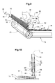
- FIG. 3 shows a detail of that in FIGS. 1 and 2 shown embodiments of the inventive Device, namely partially the feed conveyor 12, the Stack support 10 with the support plate 30 of the adhesion roller 32 and the object stop 28, the Wegschiebean Aunt 56 with the sliding gear 58 and the Sucker assembly 36.
- the suction head 38 is in an extended position Takeover position 48 with its suction opening 42 in Appendix. on the top article 14 of the stack 16.
- the by a Pusher arm 60 the longitudinal extent seen in view approximately coincides with the longitudinal axis of the suction head 38, engages with his nose 66 an object 14, the previously by means of the sucker arrangement 36 from the stack 16 has been lifted.
- the supported by the nose 66 and with its trailing edge 34 on the flank 64 adjoining object 14 is in Wegschiebecardi W from the stack 16 in the direction of the object stop 28th pushed.
- the articles 14 become, as in Figs. 1 and 2 also shown by means of the feed conveyor 12 in one Schuppenformation S of the stack support 10 fed, in which each object on the respectively preceding rests and wherein the folded edge of the articles 14 the trailing edge 34 forms.
- FIG. 4 shows the same representation as FIG. 3 Short time later, according to the in Fig. 3 illustrated situation.
- the suction head 38 has the uppermost Item 14 of the stack 16 raised, which now with its overhead flat side on the stop 68 of the Sliding member 62 is applied, which the previous lifted object 14 in the direction against the Object stop 28 from the stack 16 abschiebt.
- On the one hand prevents the suction head 38, that of him 14 raised object still partially on this resting object 14, which in the direction against the Subject stop 28 is pushed, is taken and on the other hand, due to the concern of the raised Item 14 at the stop 68 won time, which allows a possibly mite lifted next item 14 is from the raised one Can solve the object 14.
- FIG. 6 shows an object stop 28 passing leading, driven in the conveying direction F.
- Removal conveyor 80 ' which on a rotating traction member in Distance one behind the other arranged transport brackets 84th which are intended to each of the stack 16 pushed away and with its leading edge 34 'applied to the object stop 28 object 14 to capture and promote.
- Transport brackets 84 of are shown, for example, in WO-A-99/30996 disclosed.
- Figs. 1-6 are usually the stack support 10 continuously articles 14th fed. Also, the stack 16 becomes continuous dismantled above. The stack 16 thus forms a buffer to Phase shifts between the supply of the Articles 14 for stacking and dismantling the stack, Irregularities in the feeder or short-term Interruptions both infeed and on site take.
- FIG. 7 shows in a similar representation as FIGS. 6 shows a part of the device according to the invention with the Stack support 10, the feed conveyor 12, the sucker assembly 36 and the Wegschiebean Aunt 56th
- the otherwise the same as shown in Figures 1 - 6 executed stack support 10th further comprises a tongue-shaped support element 86, which in the region of the downstream end of Stack support 10 is pivotally mounted - the bearing axis is designated 88 - and towards the Feed conveyor 12 over about 3 ⁇ 4 of the length of the stack support 10th extends.
- the feeder 12 facing end portion is bent towards the bottom.
- the support member 86 in from the support plate 18 and the ribbon conveyor 20th defined support level.
- a cylinder-Kolbenagregats 90 is the support member 86 from the shown position raised and optionally lowered, such as shown in Figs. 8 and 9 and in connection with to describe these figures will be.
- the suction head 38 is in a fully extended takeover position 48. Between this and the retracted input position 48 'leads the Suction head 38 a maximum stroke H. In the shown extended takeover position 48 is the suction head 38th far from the stack support 10 spaced that some Objects 14, for example 3 - 4 thicker objects or 8 - 12 thinner objects, find space.
- Dash-dot is a stack 16 with maximum allowable Stack height indicated. Is the topmost one Item 14 of the stack 16 between the maximum extended takeover position 48 of the suction head 38 and the maximum allowable stack height is done by means of Sucker assembly 36 a reliable removal of the stack 16; the resulting work area of the Sucker assembly 36 is indicated by the double arrow 92.
- FIG. 9 shows in the same representation as FIGS. 3 to 6 a further embodiment of the inventive Device, wherein the feed conveyor 12, the sucker arrangement 36 and the Wegschiebean Aunt 56 are identical, as in all previously described embodiments. Also, the support plate 30 and the adhesion roller 32 are available accordingly.
- the stack support 10 with the Support plate 18, the ribbon conveyor 20 and the Stop plate 26 is the same, as in the further The above-described embodiments, however, is the Stack support 10, for example, at its in the feed direction Z seen downstream end pivotally mounted, so that the stack support 10 at its the feeder 12th facing end indicated by the dash-dotted lines normal working position down into one with pulled out Lines shown pivoting position can be spent.
- the stack support 10 may for example by means of a Spring towards up against a stop in the spring normal work situation.
- cylinder-piston unit 90 shown serve by the Piston relative to the position shown in FIG. 7 is further retracted into the cylinder, the Support member 68, the support plate 18 and the Ribbon conveyor 20 pivoting in a clockwise direction entraining.
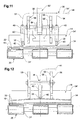
- Wegschiebean Aunt 56th preferably two coaxially mounted spaced apart sprockets 58, as shown in FIG Fig. 11 is shown. These sit up against rotation the same driven in the direction of displacement W shaft 58 '.
- Each of these slides 58 is a suction head 38th associated, in the preferred direction in the direction of the shaft 58 'seen outside the sliding wheels 58 is located.
- the suction openings 42 of the suction heads 38 are via hoses 54 with each other and via a common supply hose 54 'connected to the vacuum source 44.
- a transport bracket 84 of a Outfeed conveyor 80 'shown between the shaft 58' and the stack support 10 passes through and destined for is, in each case lifted from the stack 16 and by means of Push-away assembly 56 pushed away from the stack Item 14 at the trailing edge 34 to capture and promote.
- the better clarity For the sake of brevity, only those transport brackets 84 are shown the previously raised and away from the stack 16 pushed object 14 has detected.
- FIG. 1 operates as follows.
- the objects 14 in a scale formation S of the stack support 12th supplied, in which each object on the trailing rests.
- each object on the trailing rests In the example shown is the Folded edge of the folded articles 14 the trailing Edge 34.
- Support by the ribbon conveyor 20 becomes on the stack support 10 of the bottom loaded stack 16 formed.
- the sliding wheel 58, the associated Andrückband 74 and the removal conveyor 80 can already move be set.
- the Suction heads 38 connected to the vacuum source 44 whereby the top object 14 lifted off the stack 16 becomes.
- the lifting and pushing off of the objects takes place as shown in FIGS. 3-6 and in connection with the Description of these figures executed.
- the Moving away from the stack 16 have the objects 14th with respect to the sliding wheel 58 an undershot position, which, however, turns into an overshot position, if the lifted and pushed away object 14 with his leading edge 34 'abuts the object stop 28 and the associated sliding member 62 in the at Trailing edge 34 raised adjacent end portion becomes.
- the stack 16 is made to work and dismantle the exact same way as related to of Fig. 1 and Figs. 3 - 6 described above.
- lifted objects 14 are about the pulley 78 deflected, whereby in the supplied scale flow S trailing edge 34 of the objects 14 now to leading edge becomes.
- Guide roller 78 is located in the means of the removal conveyor 80th path led dandruff formation every object on the each leading up.
- suction cups 38 shown instead of the suction cups 38 shown also after the venturi effect working compressed air suction be used.
- any automatic sucker arrangement used automatically after release by a pushed-away object 14 the next lifting the top article 14 from the stack 16 and a relatively large work area 92 has.
Landscapes
- Engineering & Computer Science (AREA)
- Mechanical Engineering (AREA)
- Sheets, Magazines, And Separation Thereof (AREA)
- Stacking Of Articles And Auxiliary Devices (AREA)
- Load-Engaging Elements For Cranes (AREA)
- Pile Receivers (AREA)
Abstract
Description
- Fig. 1
- in Ansicht eine erste Ausbildungsform der erfindungsgemässen Vorrichtung;
- Fig. 2
- ebenfalls in Ansicht eine zweite Ausbildungsform der erfindungsgemässen Vorrichtung;
- Fig. 3
- gegenüber Fig. 1 und 2 vergrössert einen Teil der dort gezeigten Vorrichtungen zu einem Zeitpunkt, zu welchem eine Saugeranordnung den obersten Gegenstand eines Stapels erfasst;
- Fig. 4
- in gleicher Darstellung wie Fig. 3 die Vorrichtung zu einem Zeitpunkt, zu welchem die Saugeranordnung den erfassten Gegenstand angehoben hat, so dass dieser an einem Anschlag eines Schiebeorgans anliegt;
- Fig. 5
- in gleicher Darstellung wie Fig. 3 und 4 die Vorrichtung zu einem späteren Zeitpunkt, zu welchem der erfasste Gegenstand vollständig angehoben ist;
- Fig. 6
- in gleicher Darstellung, wie die Fig. 3 - 5 die Vorrichtung zu einem Zeitpunkt, zu welchem der vollständig angehobene Gegenstand von einem Schiebeorgan vom Saugkopf der Sauganordnung weggeschoben wird.
- Fig. 7
- in ähnlicher Darstellung wie in den Fig. 3 - 6 eine Ausbildungsform der erfindungsgemässen Vorrichtung mit einem schwenkbaren Auflageelement der Stapelauflage;
- Fig. 8
- in gleicher Darstellung wie Fig. 7 die dort gezeigte Vorrichtung mit gegen oben verschwenktem Auflageelement;
- Fig. 9
- in gleicher Darstellung wie Fig. 3 - 8 eine Ausbildungsform der erfindungsgemässen Vorrichtung mit einer schwenkbaren Stapelauflage;
- Fig. 10
- im Längsschnitt einen Saugkopf der Saugeranordnung;
- Fig. 11
- in Seitenansicht eine erfindungsgemässe Vorrichtung mit zwei Schieberädern und zwei diesen zugeordneten Saugköpfen sowie einem Klammertransporteur zum Wegfördern der angehobenen und weggeschobenen Gegenstände; und
- Fig. 12
- ebenfalls in Seitenansicht eine weitere Ausbildungsform mit zwei Schieberädern und einem einzigen mittig zwischen diesen angeordneten Saugkopf.
Claims (13)
- Vorrichtung zum Abbauen eines Stapels von flächigen Gegenständen, insbesondere Druckereierzeugnissen, mit einer Stapelauflage (10) für die Aufnahme eines von unten beschickten Stapels (16), einer oberhalb der Stapelauflage (10) angeordneten Saugeranordnung (36) mit einem Saugkopf (38) zum Anheben des jeweils obersten Gegenstandes (14) des Stapels (16), und einer Wegschiebeanordnung (56) mit in einer Wegschieberichtung (W) umlaufend angetriebenen, hintereinander angeordneten Schiebeorganen (62), die dazu bestimmt sind, den jeweils mittels der Saugeranordnung (36) in eine Abgabeposition (48') angehobenen Gegenstand (14) bei dessen in Wegschieberichtung (W) nachlaufenden Kante (34) zu untergreifen und durch Einwirken auf die nachlaufende Kante (34) vom Saugkopf (38) weg zu schieben, wobei der Saugkopf (38) selbsttätig nach der Freigabe durch den weggeschobenen Gegenstand (14) den nächsten Gegenstand (14) ab dem Stapel (16) abhebt, dadurch gekennzeichnet, dass die Saugeranordnung (36) und die Wegschiebeanordnung (56) in einem festen Abstand oberhalb der Stapelauflage (10) angeordnet sind und die Schiebeorgane (62) an ihrer, beim Wegschieben eines Gegenstandes (14) vom Saugkopf (38) der Stapelauflage (10) zugewandten Stirnseite einen Anschlag (68) für den jeweils nächsten mittels des Saugkopfes (38) ab dem Stapel (16) abgehobenen Gegenstand (14) aufweisen.
- Vorrichtung nach Anspruch 1, dadurch gekennzeichnet, dass die Schiebeorgane (62) an einem sternförmigen, um seine Achse drehend angetriebenen Schieberad (58) ausgebildet sind.
- Vorrichtung nach Anspruch 1 oder 2, gekennzeichnet durch zwei koaxial und in einen Abstand angeordnete, synchron angetriebene Schieberäder (58).
- Vorrichtung nach Anspruch 3, dadurch gekennzeichnet, dass wenigstens annähernd mittig zwischen den Schieberädern (58) ein Saugkopf (38) angeordnet ist.
- Vorrichtung nach Anspruch 3, dadurch gekennzeichnet, dass jedem der Schieberäder (58) ein Saugkopf (38) zugeordnet ist.
- Vorrichtung nach einem der Ansprüche 1 bis 5, dadurch gekennzeichnet, dass der Saugkopf (38) eine an eine Unterdruckquelle (44) anschliessbare Saugöffnung (42) aufweist, in einem fest angeordneten Führungselement (40) längsgeführt und mittels eines Rückstellelements (46) in Richtung gegen eine ausgefahrene Übernahmeposition (48) gedrängt und bei durch einen Gegenstand (14) abgedeckter Saugöffnung (42) gegen die Kraft des Rückstellelements (46) aus der Übernahmeposition (48) in die eingefahrene Abgabeposition (48') bewegbar ist.
- Vorrichtung nach Anspruch 5 und 6, dadurch gekennzeichnet, dass die Saugöffnungen (42) der beiden Saugköpfe (38) miteinander und mit einer Unterdruckquelle (44) strömungsverbunden sind.
- Vorrichtung nach einem der Ansprüche 1 bis 7, dadurch gekennzeichnet, dass die Stapelauflage (10) ein Auflageelement (86) aufweist, das - für den vollständigen Abbau des Stapels (16) und/oder zum vorübergehenden Anheben des Stapels (16), um das Einlaufen eines einer Lücke in einem dem Stapel (16) zugeführten Gegenständestrom (S) folgenden Gegenstand (14) unter den Stapel (16) zu ermöglichen - aus einer von der Stapelauflage (10) definierten Auflagefläche in Richtung gegen die Sauganordnung (36) bewegbar ist.
- Vorrichtung nach einem der Ansprüche 1 bis 8, dadurch gekennzeichnet, dass die Stapelauflage (10) mit ihrer einem Zuförderer (12) zugewandten Seite in Richtung gegen unten schwenkbar ist.
- Vorrichtung nach einem der Ansprüche 1 bis 11, dadurch gekennzeichnet, dass in Wegschieberichtung (W) stromabwärts der Stapelauflage (10), in einem Abstand vom Schieberad (58) , der kleiner ist als die in Wegschieberichtung (w) gemessene Länge (L) der Gegenstände (14), ein Gegenstandanschlag (28) für die vorauslaufende Kante (34') der weggeschobenen Gegenstände (14) angeordnet ist, um die Gegenstände (14) mittels der Schiebeorgane (62) bezüglich des Schieberades (58) von einer unterschlächtigen in eine oberschlächtige Lage zu verbringen.
- Vorrichtung nach Anspruch 10, dadurch gekennzeichnet, dass ein Andrückband (74) zusammen mit dem Schieberad (58) einen Förderspalt (76) bildet um die Gegenstände (14) oberschlächtig wegzufördern.
- Vorrichtung nach Anspruch 10, gekennzeichnet durch eine Umlenkwalze (82) und ein mit dieser einen Förderspalt (76) bildendes Andrückelement (74) zum Umlenken der in die oberschlächtige Lage verbrachten Gegenstände (14) um die Umlenkwalze (82).
- Vorrichtung nach Anspruch 10, gekennzeichnet durch einen Transportklammern (84) aufweisenden Wegförderer (80'), dessen Transportklammern (84) dazu bestimmt sind, jeweils einen mit seiner vorauslaufenden Kante (34') gegen den Gegenstandanschlag (28) geschobenen Gegenstand (14) zu fassen und wegzufördern.
Applications Claiming Priority (2)
| Application Number | Priority Date | Filing Date | Title |
|---|---|---|---|
| CH21242003 | 2003-12-12 | ||
| CH21242003 | 2003-12-12 |
Publications (2)
| Publication Number | Publication Date |
|---|---|
| EP1541508A1 true EP1541508A1 (de) | 2005-06-15 |
| EP1541508B1 EP1541508B1 (de) | 2008-04-16 |
Family
ID=34468811
Family Applications (1)
| Application Number | Title | Priority Date | Filing Date |
|---|---|---|---|
| EP04021996A Expired - Lifetime EP1541508B1 (de) | 2003-12-12 | 2004-09-16 | Vorrichtung zum Abbauen eines Stapels von flächigen Gegenständen |
Country Status (4)
| Country | Link |
|---|---|
| EP (1) | EP1541508B1 (de) |
| AT (1) | ATE392384T1 (de) |
| DE (1) | DE502004006833D1 (de) |
| DK (1) | DK1541508T3 (de) |
Cited By (4)
| Publication number | Priority date | Publication date | Assignee | Title |
|---|---|---|---|---|
| CH702403A1 (de) * | 2009-12-07 | 2011-06-15 | Ferag Ag | Verfahren zum Entkoppeln zweier aufeinanderfolgender Produkteströme von Druckprodukten sowie Vorrichtung zur Durchführung des Verfahrens. |
| WO2021018979A1 (en) | 2019-07-30 | 2021-02-04 | Anheuser-Busch Inbev S.A. | Denesting apparatus |
| EP3842369A1 (de) | 2019-12-27 | 2021-06-30 | Anheuser-Busch InBev S.A. | Entstapelungsgerät |
| CN119330118A (zh) * | 2024-12-18 | 2025-01-21 | 天津市金来包装制品工贸有限公司 | 一种瓦楞纸生产加工用输送装置 |
Citations (5)
| Publication number | Priority date | Publication date | Assignee | Title |
|---|---|---|---|---|
| EP0691296A1 (de) * | 1994-07-07 | 1996-01-10 | Holzma-Maschinenbau GmbH | Beschickungseinrichtung für Plattenaufteilsägen |
| EP0755886A1 (de) * | 1995-07-25 | 1997-01-29 | Ferag AG | Vorrichtung zum Zubringen von Druckereiprodukten zu einer Weiterverarbeitungsstelle |
| EP0806391A1 (de) * | 1996-05-06 | 1997-11-12 | Ferag AG | Vorrichtung zum Zubringen von Druckereierzeugnissen zu einer Weiterverarbeitungsstelle |
| US5803445A (en) * | 1995-07-31 | 1998-09-08 | Ferag Ag | Arrangement for delivering printed products to a removal conveyor |
| WO2000046135A1 (de) * | 1999-02-05 | 2000-08-10 | Ferag Ag | Vorrichtung zum abbauen eines stapels von flächigen gegenständen, insbesondere druckereierzeugnissen |
-
2004
- 2004-09-16 AT AT04021996T patent/ATE392384T1/de active
- 2004-09-16 EP EP04021996A patent/EP1541508B1/de not_active Expired - Lifetime
- 2004-09-16 DE DE502004006833T patent/DE502004006833D1/de not_active Expired - Lifetime
- 2004-09-16 DK DK04021996T patent/DK1541508T3/da active
Patent Citations (5)
| Publication number | Priority date | Publication date | Assignee | Title |
|---|---|---|---|---|
| EP0691296A1 (de) * | 1994-07-07 | 1996-01-10 | Holzma-Maschinenbau GmbH | Beschickungseinrichtung für Plattenaufteilsägen |
| EP0755886A1 (de) * | 1995-07-25 | 1997-01-29 | Ferag AG | Vorrichtung zum Zubringen von Druckereiprodukten zu einer Weiterverarbeitungsstelle |
| US5803445A (en) * | 1995-07-31 | 1998-09-08 | Ferag Ag | Arrangement for delivering printed products to a removal conveyor |
| EP0806391A1 (de) * | 1996-05-06 | 1997-11-12 | Ferag AG | Vorrichtung zum Zubringen von Druckereierzeugnissen zu einer Weiterverarbeitungsstelle |
| WO2000046135A1 (de) * | 1999-02-05 | 2000-08-10 | Ferag Ag | Vorrichtung zum abbauen eines stapels von flächigen gegenständen, insbesondere druckereierzeugnissen |
Cited By (5)
| Publication number | Priority date | Publication date | Assignee | Title |
|---|---|---|---|---|
| CH702403A1 (de) * | 2009-12-07 | 2011-06-15 | Ferag Ag | Verfahren zum Entkoppeln zweier aufeinanderfolgender Produkteströme von Druckprodukten sowie Vorrichtung zur Durchführung des Verfahrens. |
| WO2021018979A1 (en) | 2019-07-30 | 2021-02-04 | Anheuser-Busch Inbev S.A. | Denesting apparatus |
| US12286318B2 (en) | 2019-07-30 | 2025-04-29 | Anheuser-Busch Inbev S.A. | Denesting apparatus |
| EP3842369A1 (de) | 2019-12-27 | 2021-06-30 | Anheuser-Busch InBev S.A. | Entstapelungsgerät |
| CN119330118A (zh) * | 2024-12-18 | 2025-01-21 | 天津市金来包装制品工贸有限公司 | 一种瓦楞纸生产加工用输送装置 |
Also Published As
| Publication number | Publication date |
|---|---|
| DK1541508T3 (da) | 2008-07-14 |
| ATE392384T1 (de) | 2008-05-15 |
| EP1541508B1 (de) | 2008-04-16 |
| DE502004006833D1 (de) | 2008-05-29 |
Similar Documents
| Publication | Publication Date | Title |
|---|---|---|
| DE2315813C3 (de) | Vorrichtung zum Stapeln von bogenförmigem Material | |
| EP0366038B1 (de) | Einrichtung zum zickzackförmigen Falten und Stapeln einer Materialbahn | |
| EP0503531A1 (de) | Vorrichtung zur Bildung einer Folge von sich unterlappenden Gegenständen | |
| EP2870093A1 (de) | Vorrichtung und verfahren zum vereinzeln von wertdokumenten, sowie wertdokumentbearbeitungssystem | |
| EP1622778B2 (de) | Vorrichtung und verfahren zum einfüllen von blättern in ein kuvert | |
| EP0368009A1 (de) | Verfahren und Vorrichtung zum Fördern von Druckereiprodukten | |
| AT406577B (de) | Vorrichtung zum entstapeln von behältern | |
| EP0407763B1 (de) | Vorrichtung zum Übernehmen von Druckereierzeugnissen von einem drehend angetriebenen Schaufelrad einer Druckereimaschine | |
| DE2206682C3 (de) | ||
| EP0300171B1 (de) | Transporteur für flächige Erzeugnisse, insbesondere Druckprodukte | |
| DE2258354A1 (de) | Einrichtung zum weitertransport von von einer mehrfachschneidmaschine ausgeworfenen blaettern | |
| EP1541508B1 (de) | Vorrichtung zum Abbauen eines Stapels von flächigen Gegenständen | |
| EP1657200B1 (de) | Vorrichtung zum Trennen eines geförderten Stromes von geschuppt übereinander liegenden, flachen Werkstücken | |
| CH667065A5 (de) | Einrichtung zum herstellen von mit einem deckblatt versehenen stapeln von druckprodukten. | |
| EP0869095B1 (de) | Stapelvorrichtung | |
| WO2009141119A2 (de) | Vorrichtung zur bildung von stapelpaketen | |
| EP0451091A1 (de) | Bogenanleger | |
| DE1756949B2 (de) | Vorrichtung zum ueberfuehren blattfoermiger werkstuecke | |
| EP1360131B1 (de) | Vorrichtung und verfahren zum abbau eines stapels flacher gegenstände | |
| DE2112353B2 (de) | Verfahren und Vorrichtung zum Trennen einer schuppenförmigen Folge von von einer Schlauchziehmaschine hergestellten Schlauchabschnitten für das Bilden von abgezählten Stapel a | |
| DE102005035332B4 (de) | Vorrichtung zum Zusammentragen von Druckbogen | |
| DE4022350A1 (de) | Foerdereinrichtung fuer lageneinheiten | |
| DE2520388A1 (de) | Kuehlbett fuer eine walzwerkanlage | |
| EP1607356A2 (de) | Vorrichtung zur Ausrichtung von in einer Lage übereinander angeordneten Bogen | |
| EP1748012B1 (de) | Verfahren und Vorrichtung zum Zusammentragen von Druckbogen |
Legal Events
| Date | Code | Title | Description |
|---|---|---|---|
| PUAI | Public reference made under article 153(3) epc to a published international application that has entered the european phase |
Free format text: ORIGINAL CODE: 0009012 |
|
| AK | Designated contracting states |
Kind code of ref document: A1 Designated state(s): AT BE BG CH CY CZ DE DK EE ES FI FR GB GR HU IE IT LI LU MC NL PL PT RO SE SI SK TR |
|
| AX | Request for extension of the european patent |
Extension state: AL HR LT LV MK |
|
| 17P | Request for examination filed |
Effective date: 20050423 |
|
| AKX | Designation fees paid |
Designated state(s): AT BE BG CH CY CZ DE DK EE ES FI FR GB GR HU IE IT LI LU MC NL PL PT RO SE SI SK TR |
|
| GRAP | Despatch of communication of intention to grant a patent |
Free format text: ORIGINAL CODE: EPIDOSNIGR1 |
|
| GRAS | Grant fee paid |
Free format text: ORIGINAL CODE: EPIDOSNIGR3 |
|
| GRAA | (expected) grant |
Free format text: ORIGINAL CODE: 0009210 |
|
| AK | Designated contracting states |
Kind code of ref document: B1 Designated state(s): AT BE BG CH CY CZ DE DK EE ES FI FR GB GR HU IE IT LI LU MC NL PL PT RO SE SI SK TR |
|
| REG | Reference to a national code |
Ref country code: CH Ref legal event code: EP Ref country code: CH Ref legal event code: NV Representative=s name: PATENTANWAELTE SCHAAD, BALASS, MENZL & PARTNER AG |
|
| REG | Reference to a national code |
Ref country code: IE Ref legal event code: FG4D Free format text: LANGUAGE OF EP DOCUMENT: GERMAN |
|
| REF | Corresponds to: |
Ref document number: 502004006833 Country of ref document: DE Date of ref document: 20080529 Kind code of ref document: P |
|
| REG | Reference to a national code |
Ref country code: SE Ref legal event code: TRGR |
|
| REG | Reference to a national code |
Ref country code: DK Ref legal event code: T3 |
|
| PG25 | Lapsed in a contracting state [announced via postgrant information from national office to epo] |
Ref country code: SI Free format text: LAPSE BECAUSE OF FAILURE TO SUBMIT A TRANSLATION OF THE DESCRIPTION OR TO PAY THE FEE WITHIN THE PRESCRIBED TIME-LIMIT Effective date: 20080416 |
|
| NLV1 | Nl: lapsed or annulled due to failure to fulfill the requirements of art. 29p and 29m of the patents act | ||
| PG25 | Lapsed in a contracting state [announced via postgrant information from national office to epo] |
Ref country code: PT Free format text: LAPSE BECAUSE OF FAILURE TO SUBMIT A TRANSLATION OF THE DESCRIPTION OR TO PAY THE FEE WITHIN THE PRESCRIBED TIME-LIMIT Effective date: 20080916 Ref country code: NL Free format text: LAPSE BECAUSE OF FAILURE TO SUBMIT A TRANSLATION OF THE DESCRIPTION OR TO PAY THE FEE WITHIN THE PRESCRIBED TIME-LIMIT Effective date: 20080416 Ref country code: FI Free format text: LAPSE BECAUSE OF FAILURE TO SUBMIT A TRANSLATION OF THE DESCRIPTION OR TO PAY THE FEE WITHIN THE PRESCRIBED TIME-LIMIT Effective date: 20080416 Ref country code: ES Free format text: LAPSE BECAUSE OF FAILURE TO SUBMIT A TRANSLATION OF THE DESCRIPTION OR TO PAY THE FEE WITHIN THE PRESCRIBED TIME-LIMIT Effective date: 20080727 Ref country code: BG Free format text: LAPSE BECAUSE OF FAILURE TO SUBMIT A TRANSLATION OF THE DESCRIPTION OR TO PAY THE FEE WITHIN THE PRESCRIBED TIME-LIMIT Effective date: 20080716 |
|
| PG25 | Lapsed in a contracting state [announced via postgrant information from national office to epo] |
Ref country code: PL Free format text: LAPSE BECAUSE OF FAILURE TO SUBMIT A TRANSLATION OF THE DESCRIPTION OR TO PAY THE FEE WITHIN THE PRESCRIBED TIME-LIMIT Effective date: 20080416 |
|
| REG | Reference to a national code |
Ref country code: IE Ref legal event code: FD4D |
|
| PG25 | Lapsed in a contracting state [announced via postgrant information from national office to epo] |
Ref country code: CZ Free format text: LAPSE BECAUSE OF FAILURE TO SUBMIT A TRANSLATION OF THE DESCRIPTION OR TO PAY THE FEE WITHIN THE PRESCRIBED TIME-LIMIT Effective date: 20080416 Ref country code: IE Free format text: LAPSE BECAUSE OF FAILURE TO SUBMIT A TRANSLATION OF THE DESCRIPTION OR TO PAY THE FEE WITHIN THE PRESCRIBED TIME-LIMIT Effective date: 20080416 |
|
| PLBE | No opposition filed within time limit |
Free format text: ORIGINAL CODE: 0009261 |
|
| STAA | Information on the status of an ep patent application or granted ep patent |
Free format text: STATUS: NO OPPOSITION FILED WITHIN TIME LIMIT |
|
| EN | Fr: translation not filed | ||
| PG25 | Lapsed in a contracting state [announced via postgrant information from national office to epo] |
Ref country code: RO Free format text: LAPSE BECAUSE OF FAILURE TO SUBMIT A TRANSLATION OF THE DESCRIPTION OR TO PAY THE FEE WITHIN THE PRESCRIBED TIME-LIMIT Effective date: 20080416 Ref country code: SK Free format text: LAPSE BECAUSE OF FAILURE TO SUBMIT A TRANSLATION OF THE DESCRIPTION OR TO PAY THE FEE WITHIN THE PRESCRIBED TIME-LIMIT Effective date: 20080416 |
|
| 26N | No opposition filed |
Effective date: 20090119 |
|
| BERE | Be: lapsed |
Owner name: FERAG AG Effective date: 20080930 |
|
| PG25 | Lapsed in a contracting state [announced via postgrant information from national office to epo] |
Ref country code: MC Free format text: LAPSE BECAUSE OF NON-PAYMENT OF DUE FEES Effective date: 20080930 Ref country code: EE Free format text: LAPSE BECAUSE OF FAILURE TO SUBMIT A TRANSLATION OF THE DESCRIPTION OR TO PAY THE FEE WITHIN THE PRESCRIBED TIME-LIMIT Effective date: 20080416 |
|
| PG25 | Lapsed in a contracting state [announced via postgrant information from national office to epo] |
Ref country code: BE Free format text: LAPSE BECAUSE OF NON-PAYMENT OF DUE FEES Effective date: 20080930 |
|
| PG25 | Lapsed in a contracting state [announced via postgrant information from national office to epo] |
Ref country code: CY Free format text: LAPSE BECAUSE OF FAILURE TO SUBMIT A TRANSLATION OF THE DESCRIPTION OR TO PAY THE FEE WITHIN THE PRESCRIBED TIME-LIMIT Effective date: 20080416 |
|
| PG25 | Lapsed in a contracting state [announced via postgrant information from national office to epo] |
Ref country code: LU Free format text: LAPSE BECAUSE OF NON-PAYMENT OF DUE FEES Effective date: 20080916 Ref country code: HU Free format text: LAPSE BECAUSE OF FAILURE TO SUBMIT A TRANSLATION OF THE DESCRIPTION OR TO PAY THE FEE WITHIN THE PRESCRIBED TIME-LIMIT Effective date: 20081017 |
|
| PG25 | Lapsed in a contracting state [announced via postgrant information from national office to epo] |
Ref country code: TR Free format text: LAPSE BECAUSE OF FAILURE TO SUBMIT A TRANSLATION OF THE DESCRIPTION OR TO PAY THE FEE WITHIN THE PRESCRIBED TIME-LIMIT Effective date: 20080416 |
|
| PG25 | Lapsed in a contracting state [announced via postgrant information from national office to epo] |
Ref country code: GR Free format text: LAPSE BECAUSE OF FAILURE TO SUBMIT A TRANSLATION OF THE DESCRIPTION OR TO PAY THE FEE WITHIN THE PRESCRIBED TIME-LIMIT Effective date: 20080717 |
|
| PGFP | Annual fee paid to national office [announced via postgrant information from national office to epo] |
Ref country code: GB Payment date: 20110920 Year of fee payment: 8 |
|
| PG25 | Lapsed in a contracting state [announced via postgrant information from national office to epo] |
Ref country code: FR Free format text: LAPSE BECAUSE OF FAILURE TO SUBMIT A TRANSLATION OF THE DESCRIPTION OR TO PAY THE FEE WITHIN THE PRESCRIBED TIME-LIMIT Effective date: 20090227 |
|
| GBPC | Gb: european patent ceased through non-payment of renewal fee |
Effective date: 20120916 |
|
| PG25 | Lapsed in a contracting state [announced via postgrant information from national office to epo] |
Ref country code: GB Free format text: LAPSE BECAUSE OF NON-PAYMENT OF DUE FEES Effective date: 20120916 |
|
| PGFP | Annual fee paid to national office [announced via postgrant information from national office to epo] |
Ref country code: AT Payment date: 20140911 Year of fee payment: 11 |
|
| PGFP | Annual fee paid to national office [announced via postgrant information from national office to epo] |
Ref country code: SE Payment date: 20150923 Year of fee payment: 12 |
|
| PGFP | Annual fee paid to national office [announced via postgrant information from national office to epo] |
Ref country code: IT Payment date: 20150924 Year of fee payment: 12 Ref country code: DK Payment date: 20150918 Year of fee payment: 12 |
|
| REG | Reference to a national code |
Ref country code: AT Ref legal event code: MM01 Ref document number: 392384 Country of ref document: AT Kind code of ref document: T Effective date: 20150916 |
|
| PG25 | Lapsed in a contracting state [announced via postgrant information from national office to epo] |
Ref country code: AT Free format text: LAPSE BECAUSE OF NON-PAYMENT OF DUE FEES Effective date: 20150916 |
|
| PGFP | Annual fee paid to national office [announced via postgrant information from national office to epo] |
Ref country code: DE Payment date: 20160921 Year of fee payment: 13 |
|
| REG | Reference to a national code |
Ref country code: DK Ref legal event code: EBP Effective date: 20160930 |
|
| PG25 | Lapsed in a contracting state [announced via postgrant information from national office to epo] |
Ref country code: SE Free format text: LAPSE BECAUSE OF NON-PAYMENT OF DUE FEES Effective date: 20160917 |
|
| REG | Reference to a national code |
Ref country code: SE Ref legal event code: EUG |
|
| REG | Reference to a national code |
Ref country code: DE Ref legal event code: R082 Ref document number: 502004006833 Country of ref document: DE Representative=s name: KLUNKER IP PATENTANWAELTE PARTG MBB, DE |
|
| PG25 | Lapsed in a contracting state [announced via postgrant information from national office to epo] |
Ref country code: IT Free format text: LAPSE BECAUSE OF NON-PAYMENT OF DUE FEES Effective date: 20160916 |
|
| PG25 | Lapsed in a contracting state [announced via postgrant information from national office to epo] |
Ref country code: DK Free format text: LAPSE BECAUSE OF NON-PAYMENT OF DUE FEES Effective date: 20160930 |
|
| REG | Reference to a national code |
Ref country code: DE Ref legal event code: R119 Ref document number: 502004006833 Country of ref document: DE |
|
| PG25 | Lapsed in a contracting state [announced via postgrant information from national office to epo] |
Ref country code: DE Free format text: LAPSE BECAUSE OF NON-PAYMENT OF DUE FEES Effective date: 20180404 |
|
| PGFP | Annual fee paid to national office [announced via postgrant information from national office to epo] |
Ref country code: CH Payment date: 20181128 Year of fee payment: 15 |
|
| REG | Reference to a national code |
Ref country code: CH Ref legal event code: PL |
|
| PG25 | Lapsed in a contracting state [announced via postgrant information from national office to epo] |
Ref country code: LI Free format text: LAPSE BECAUSE OF NON-PAYMENT OF DUE FEES Effective date: 20190930 Ref country code: CH Free format text: LAPSE BECAUSE OF NON-PAYMENT OF DUE FEES Effective date: 20190930 |